1
Linksys PAP2 and RT31P2
PHONE ADAPTER Administration Guide
August 2004
© 2004 Linksys Proprietary (See Copyright Notice on Page 2)
1
Disclaimer – Please Read:
This document contains implementation examples and techniques using Linksys and,
in some instances, other company’s technology and products and is a
recommendation only and does not constitute any legal arrangement between
Linksys and the reader, either written or implied. The conclusions reached and
recommendations and statements made are based on generic network, service and
application requirements and should be regarded as a guide to assist you in forming
your own opinions and decision regarding your particular situation. As well, Linksys
Technology reserves the right to change the features and functionalities for products
described in this document at any time. These changes may involve changes to the
described solutions over time.
Use of Proprietary Information and Copyright Notice:
Major portions of this document are the sole property of Sipura Technology,
Inc. and are provided to its licensee, Linksys LLC., and protected by United
States and international copyright laws. (c)2003-2004 Sipura technology,
Inc. - All rights reserved.
© 2004 Linksys Proprietary (See Copyright Notice on Page 2)
2
Table of Contents
1.
Introduction.................................................................................................................................... 6
1.1.
The Session Initiation Protocol ............................................................................................. 6
1.1.1.
Components of a SIP Network ....................................................................................................... 8
1.1.2.
Provisioning Overview.................................................................................................................... 9
1.1.3.
Security Overview .........................................................................................................................10
1.1.3.1.
Proxy Servers ......................................................................................................................11
1.1.4.
SIP Services..................................................................................................................................11
1.1.4.1.
Basic Services .....................................................................................................................12
1.1.4.2.
Enhanced Services..............................................................................................................12
1.1.4.3.
PSTN Interworking...............................................................................................................14
1.2.
1.2.1.
1.2.2.
Network Address Translation (NAT) Traversal................................................................... 15
What is a NAT or NAPT (Network Address Port Translator)? .......................................................15
VoIP-NAT Interworking..................................................................................................................16
1.3.
Voice Quality Overview....................................................................................................... 16
Hardware Overview ..................................................................................................................... 17
2.1.
Phone Adapter LED Status................................................................................................. 19
2.2.
Broadband Router (RT31P2) LED Status .......................................................................... 19
3.
Software Configuration Mechanisms........................................................................................... 20
3.1.
Configuration Profile Formats ............................................................................................. 21
2.
3.1.1.
3.1.2.
3.2.
3.3.
3.3.1.
3.3.2.
3.3.3.
3.4.
3.4.1.
3.4.2.
3.4.3.
4.
Using the Supplemental Profile Compiler......................................................................................23
Encrypting and Compressing XML configuration files ...................................................................24
Secure Initial Configuration................................................................................................. 25
Web Interface ..................................................................................................................... 26
Web Interface Conventions ...........................................................................................................26
Administration Privileges ...............................................................................................................27
Basic and Advanced Views ...........................................................................................................27
Functional Configuration URLs........................................................................................... 27
Upgrade URL ................................................................................................................................27
Resync URL ..................................................................................................................................28
Reboot URL ..................................................................................................................................28
3.5.
Configuration via the IVR (PAP2 only) ............................................................................... 29
Configuration Parameters ........................................................................................................... 32
4.1.
Data Types.......................................................................................................................... 32
4.1.1.
4.2.
Conventions ..................................................................................................................................35
Provisioning Related Parameters ....................................................................................... 35
4.2.1.
Firmware Upgrade.........................................................................................................................43
4.2.2.
Provisioning Server Redundancy ..................................................................................................46
4.2.3.
Configuring the Web Server and IVR ............................................................................................46
System Configuration ..................................................................................................................................46
4.3.
Basic Networking Configuration ......................................................................................... 47
Network Configuration .................................................................................................................................47
4.4.
4.5.
4.6.
4.6.1.
4.6.2.
4.6.3.
4.6.4.
4.6.5.
4.7.
4.7.1.
4.7.2.
4.7.3.
4.8.
4.8.1.
Basic Account Configuration............................................................................................... 48
Configuration for NAT Traversal ......................................................................................... 49
Media and SDP (Session Description Protocol) Configuration .......................................... 51
DTMF and Hookflash ....................................................................................................................51
Codec and Audio Settings.............................................................................................................52
Dynamic Payload Types and SDP Codec Names.........................................................................53
Secure Media Implementation:......................................................................................................54
Outbound Call Codec Selection Codes: ........................................................................................56
Supplementary Services..................................................................................................... 57
Supplementary Services activated internally.................................................................................58
Call Forwarding Implemented internally ........................................................................................60
Supplementary Services implemented in the service provider network.........................................60
Dial Plan Configuration ....................................................................................................... 61
Speed Dialing Settings ..................................................................................................................66
© 2004 Linksys Proprietary (See Copyright Notice on Page 2)
3
4.9.
Progress Tone and Ring Configuration .............................................................................. 67
4.9.1.
4.9.2.
4.10.
Distinctive Ring and Other Ring Settings ......................................................................................67
Progress Tones .............................................................................................................................69
Less Frequently Used Paramters ....................................................................................... 70
4.10.1.
4.10.2.
4.10.3.
4.10.4.
4.10.5.
Advanced Protocol Parameters ................................................................................................70
Additional User Account Information ........................................................................................73
Per-Line Polarity Settings .........................................................................................................75
Additional Timer Values (sec)...................................................................................................75
Miscellaneous Parameters .......................................................................................................76
5.
Expected Feature Behavior......................................................................................................... 79
5.1.
Originating a Phone Call..................................................................................................... 79
5.2.
Receiving a Phone Call ...................................................................................................... 79
5.3.
Caller ID .............................................................................................................................. 80
5.4.
Calling Line Identification Presentation (CLIP) ................................................................... 80
5.5.
Calling Line Identification Restriction (CLIR) – Caller ID Blocking ..................................... 81
5.6.
Call Waiting......................................................................................................................... 81
5.7.
Disable or Cancel Call Waiting ........................................................................................... 82
5.8.
Call-Waiting with Caller ID .................................................................................................. 83
5.9.
Voice Mail ........................................................................................................................... 83
5.10. Attendant Call Transfer....................................................................................................... 84
5.11. Unattended or “Blind” Call Transfer.................................................................................... 85
5.12. Call Hold ............................................................................................................................. 85
5.13. Three-Way Calling .............................................................................................................. 86
5.14. Three-Way Ad-Hoc Conference Calling ............................................................................. 86
5.15. Call Return .......................................................................................................................... 87
5.16. Automatic Call Back............................................................................................................ 87
5.17. Call FWD – Unconditional................................................................................................... 88
5.18. Call FWD – Busy ................................................................................................................ 89
5.19. Call FWD - No Answer........................................................................................................ 89
5.20. Anonymous Call Blocking ................................................................................................... 90
5.21. Distinctive / Priority Ringing and Call Waiting Tone ........................................................... 90
5.22. Speed Calling – Up to Eight (8) Numbers or IP Addresses................................................ 91
6.
Troubleshooting........................................................................................................................... 92
6.1.
Call Statistics Reporting...................................................................................................... 92
6.2.
Enabling Logging and Debugging ...................................................................................... 93
6.3.
Error and Log Reporting ..................................................................................................... 93
6.4.
Internal Error Codes ........................................................................................................... 93
6.5.
Provisioning and Upgrade result codes.............................................................................. 94
6.6.
Table of SIP Response Codes (Error Codes) .................................................................... 94
7.
Summary of Implemented Features and Specifications.............................................................. 95
7.1.
Data Networking Features .................................................................................................. 95
7.1.1.
7.1.2.
7.1.3.
7.1.4.
7.1.5.
7.1.6.
7.1.7.
7.1.8.
7.1.9.
7.1.10.
7.1.11.
7.2.
MAC Address (IEEE 802.3)...........................................................................................................95
IPv4 – Internet Protocol Version 4 (RFC 791) upgradeable to v6 (RFC 1883)..............................96
ARP – Address Resolution Protocol..............................................................................................96
DNS – A Record (RFC 1706), SRV Record (RFC 2782)...............................................................96
DiffServ (RFC 2475) and ToS – Type of Service (RFC 791/1349) ................................................96
DHCP Client – Dynamic Host Configuration Protocol (RFC 2131)................................................96
ICMP – Internet Control Message Protocol (RFC792) ..................................................................96
TCP – Transmission Control Protocol (RFC793)...........................................................................96
UDP – User Datagram Protocol (RFC768)....................................................................................96
RTP – Real Time Protocol (RFC 1889) (RFC 1890).................................................................96
RTCP – Real Time Control Protocol (RFC 1889) .....................................................................96
Voice Features.................................................................................................................... 96
7.2.1.
SIPv2 – Session Initiation Protocol Version 2 (RFC 3261-3265)..................................................96
7.2.1.1.
SIP Proxy Redundancy – Static or Dynamic via DNS SRV .................................................96
7.2.1.2.
Re-registration with Primary SIP Proxy Server ....................................................................96
© 2004 Linksys Proprietary (See Copyright Notice on Page 2)
4
7.2.1.3.
SIP Support in Network Address Translation Networks – NAT............................................96
7.2.2.
Codec Name Assignment..............................................................................................................96
7.2.3.
Secure Calls ..................................................................................................................................97
7.2.4.
Voice Algorithms: ..........................................................................................................................97
7.2.4.1.
G.711 (A-law and mµ-law) ...................................................................................................97
7.2.4.2.
G.726 ...................................................................................................................................97
7.2.4.3.
G.729A ................................................................................................................................97
7.2.4.4.
G.723.1 ................................................................................................................................97
7.2.5.
Codec Selection ............................................................................................................................97
7.2.6.
Dynamic Payload ..........................................................................................................................97
7.2.7.
Adjustable Audio Frames Per Packet............................................................................................97
7.2.8.
Fax Tone Detection Pass-Through................................................................................................97
7.2.9.
DTMF: In-band & Out-of-Band (RFC 2833) (SIP INFO *)..............................................................97
7.2.10.
Call Progress Tone Generation ................................................................................................98
7.2.11.
Call Progress Tone Pass Through............................................................................................98
7.2.12.
Jitter Buffer – Dynamic (Adaptive) ............................................................................................98
7.2.13.
Full Duplex Audio .....................................................................................................................98
7.2.14.
Echo Cancellation – Up to 8 ms Echo Tail ...............................................................................98
7.2.15.
Voice Activity Detection with Silence Suppression & Comfort Noise Generation .....................98
7.2.16.
Attenuation / Gain Adjustment ..................................................................................................98
7.2.17.
Signaling Hook Flash Event .....................................................................................................98
7.2.18.
Configurable Flash / Switch Hook Timer ..................................................................................99
7.2.19.
Configurable Dial Plan with Interdigit Timers............................................................................99
7.2.20.
Message Waiting Indicator Tones – MWI .................................................................................99
7.2.21.
Polarity Control .........................................................................................................................99
7.2.22.
Calling Party Control – CPC .....................................................................................................99
7.2.23.
International Caller ID Delivery .................................................................................................99
7.2.24.
Streaming Audio Server – SAS ..............................................................................................100
7.2.25.
Music On Hold – MOH............................................................................................................100
7.3.
7.3.1.
7.3.2.
7.3.3.
7.4.
7.4.1.
7.4.2.
7.4.3.
7.4.4.
7.4.5.
7.4.6.
7.4.7.
8.
9.
10.
Security Features.............................................................................................................. 102
Multiple Administration Layers (Levels and Permissions) ...........................................................102
HTTP Digest – Encrypted Authentication via MD5 (RFC 1321) ..................................................102
HTTPS with Client Certificate ......................................................................................................102
Administration and Maintenance Features ....................................................................... 102
Web Browser Administration and Configuration via Integral Web Server....................................102
Telephone Key Pad Configuration with Interactive Voice Prompts..............................................102
Automated Provisioning & Upgrade via TFTP, HTTP and HTTPS..............................................102
Periodic Notification of Upgrade Availability via NOTIFY or HTTP ..............................................102
Non-Intrusive, In-Service Upgrades ............................................................................................102
Report Generation and Event Logging ........................................................................................102
Syslog and Debug Server Records .............................................................................................102
List of all configuration parameters ........................................................................................... 102
Acronyms................................................................................................................................... 113
Glossary ................................................................................................................................ 115
© 2004 Linksys Proprietary (See Copyright Notice on Page 2)
5
1. Introduction
This guide describes basic administration and use of the Linksys Technology PHONE ADAPTER
phone adapter – an intelligent low-density Voice over IP (VoIP) gateway. The PHONE ADAPTER
enables carrier class residential and business IP Telephony services delivered over broadband or
high-speed Internet connections. By intelligent, we mean the PHONE ADAPTER maintains the states
of all the calls it terminates. It is capable of making proper decisions in reaction to user input events
(such as on/off hook or hook flash) with little or no involvement by a ‘middle-man’ server or media
gateway controller.
Examples of proper reactions are: playing dial tone, collecting DTMF digits, comparing them against a
dial plan and terminating a call. With intelligent endpoints at the edges of a network, performing the
bulk of the call processing duties, the deployment of a large network with thousands of subscribers
can scale quickly without the introduction of complicated, expensive servers. As described later in
this section, the Session Initiation Protocol (SIP) is a good choice of call signaling protocol for the
implementation of such a device in this type of network.
The phenomenal growth of broadband Internet access (DSL, Cable, FTTH, etc.), has brought the
realization of reliable packet switched IP Telephony Services with circuit switched toll-quality and
subscriber feature transparency with that of the PSTN’s CLASS feature-set. In addition to basic
offerings comparable to traditional PSTN services, many service providers have integrated their IP
Telephony offering with a large number of web-based productivity applications like unified messaging
and call management features such as, remote call forward configuration via the web. Such advances
over traditional phone services, with equal or better voice quality and lower per-minute prices, have
made IP Telephony service a viable business. In fact, IP Telephony service providers in the US and
abroad have seen their subscriber base growing at a rapid pace.
The technical challenges in deploying and operating a residential IP Telephony service, however, are
not small. One of the main challenges is to make the service transparent to subscribers: The
subscribers shall expect to use their existing phones to make or receive calls in the same way as with
the existing PSTN service. To enable this level of transparency, the IP Telephony solution has to be
tightly integrated. A key element in this end-to-end IP Telephony solution is the provision of an
endpoint device that sits at a subscriber’s premises that serves as an IP Telephony gateway or
telephone adapter. This phone adapter offers one or more standard telephone RJ-11 phone ports –
identical to the phone wall jacks at home – where the subscriber can plug in their existing telephone
equipment to access phone services. The IP Telephony gateway may connect to the IP network, like
the Internet, through an uplink Ethernet connection.
Important!! Please note: The information contained herein is not a warranty from Linksys
Customers planning to use the PHONE ADAPTER in a VoIP service deployment are warned to test
all functionality they plan to support in conjunction with the PHONE ADAPTER before putting the
PHONE ADAPTER in service. Some information in Section 1 of this guide is written for educational
purposes and describes functionality not yet implemented in the PHONE ADAPTER.
1.1.
The Session Initiation Protocol
There are many excellent articles and books that discuss the advantages of SIP.i Here are some of
the more popular details:
• SIP message constructs are very similar to those of HTTP which is well-known to be IP
Network (Internet) friendly.
• SIP is transport agnostic – meaning it can be used over TCP/IP or UDP/IP, with or without
security.
• SIP has a better chance of traversing NATs than other control protocols.
© 2004 Linksys Proprietary (See Copyright Notice on Page 2)
6
• SIP enables the implementation of intelligent endpoints to support scalable advanced
services.
In a nutshell, SIP is a distributed signaling protocol (as opposed to a centralized protocol such as
SS7, MGCP or MEGACO/H.248). With a distributive protocol, the intelligence does not necessarily
reside on a central server, but can be built into the individual endpoints. By moving the intelligence to
reside within the endpoints at the edge of the network, the processing load of the network application
and associated call servers are significantly reduced, thus making the network a very scalable
solution.
© 2004 Linksys Proprietary (See Copyright Notice on Page 2)
7
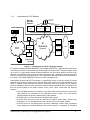
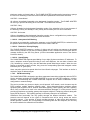
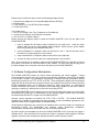
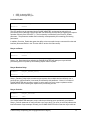
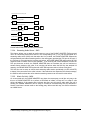
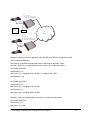
1.1.1.
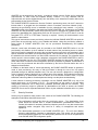
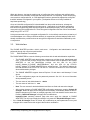
Components of a SIP Network
Subscriber
Database
Service
Provider
Domain
Provisioning
Server
Phone
Adapter
SIP
Proxy Server
Billing
Server
Application
Server
Application
Server
ISP
PSTN
Gateway
Private IP
Network
Broadband
Modem
IP
Network
PSTN
(Internet)
Router
NAT
PC
PC
PSTN
Gateway
PSTN
Gateway
Subscriber
Domain
Figure 1 -- Components of a SIP IP Telephony Network
IP Telephony Gateway (PHONE ADAPTER): The PHONE ADAPTER is a small device that sits at the
subscriber’s premises. It converts between analog telephone signals and IP Telephony signals. It has
up to two RJ-11 ports where standard analog telephones can be directly attached, and an RJ-45
interface for the Ethernet connection to the home or business LAN. Intelligence can be built into this
device to provide a wide range of features to the subscribers in association with the other elements in
the service. The PHONE ADAPTER functions as a SIP User Agent (UA).
Home/SOHO Routers with NAT Functionality: A home/SOHO router is used for routing IP packets
between the subscriber’s private network and the ISP’s public network. If the ISP provides only one
public IP address to the subscriber, the devices attached to the private network will be assigned
private IP addresses and the router will perform network address translation (NAT) on packets sent
from the private network to the public network via the router. Home routers offer the following
features:
• An R-J45 WAN interface for connection to the ISP’s public network and one or more RJ-45
LAN interfaces for connection to the subscriber’s private network. The router directs
packets between the private network and the public network.
• A PPPoE client to connect with the ISP through a DSL modem.
• A DHCP client where the router will obtain an IP address, subnet mask, default router
assignment, etc., for its WAN interface from a DHCP server on the public network.
• A DHCP server for auto-assignment of private IP addresses, subnet mask, and default
router assignment to devices attached to the private network, i.e. computers, IP Telephony
© 2004 Linksys Proprietary (See Copyright Notice on Page 2)
8
gateways, etc. The default router in this case is the IP address of the LAN interface of the
router itself.
• Performs NAT on packets sent from the private network to the public network. This is an
important feature such that recipients of the private packets will perceive them as originated
from a public IP address (the router’s WAN interface) and will therefore return messages to
the proper public IP address and port. Different routers may use different rules for
allocating port numbers at the WAN interface to forward packets from a private IP
address/port to a public IP address/port. The allocated port number is also used for routing
packets from external IP addresses to a private address. Most routers will accept a number
of static port mapping rules for forwarding packets received on a specific port at the WAN
interface to a specific IP address/port in the private network.
PSTN - VoIP Gateways: These devices are required if user agents are expected to make calls to or
receive calls from the PSTN. Many gateways may be deployed in order to service a wide area.
Gateways also behave like SIP user agents. The proxy server can be configured with cost-saving
rules based call routing information so that it may decide which gateway to use depending on the
destination and the time of the call. The IP Telephony service provider will assign each subscriber an
E164 telephone number so that it may be reached from the PSTN just like any other telephone.
Billing Servers: Billing servers are used to generate billing data per usage of the IP Telephony
service. Typically, the service provider will charge a flat fee for unlimited calls between IP Telephony
subscribers (on-net-to-on-net calls). Per use or minute chargers will be incurred only when the
subscriber makes calls to PSTN numbers (on-net-to-off-net calls) through one of the PSTN gateways.
CDR (call detail record) data are generated by the PSTN gateway and sent to the billing servers.
Provisioning Servers: Provisioning servers are used to provision the subscriber user agent devices,
e.g. the PHONE ADAPTER. When a subscriber signs up for IP Telephony service, he selects an
appropriate service level and enters his personal information including billing information. This
information is processed by the provisioning server and stored into the service provider’s customer
database. The provisioning server generates a device profile based on the subscriber’s choice of
options. The device profile, which is list of configuration parameters, is downloaded into the PHONE
ADAPTER from the provisioning server. The PHONE ADAPTER can be configured to contact the
provisioning server periodically to check for any update of the device profile, which may include a
firmware upgrade or configuration modification to the PHONE ADAPTER.
Application Servers: Application servers are used to provide value added services, such as call
forwarding, outgoing or incoming call blocking
Voice Mail Servers: Specialized servers provide voice mail services to the IP Telephony service
subscribers. When the subscriber is busy or the PHONE ADAPTER is out of service for maintenance
or other reason, incoming calls to the subscriber may be redirected to the voice mail servers where
the caller can leave a voice mail. The voice mail server will then notify the subscriber’s PHONE
ADAPTER of the availability of voice mail(s) in his mailbox. The subscriber can then contact the voice
mail server to retrieve his voice mail(s). The PHONE ADAPTER can indicate the message-waiting
status to the subscriber through a number of methods such as stuttered dial tone heard through the
telephone every time the subscriber lifts up the handset until the voice mail is retrieved.
1.1.2.
Provisioning Overview
The PHONE ADAPTER is configurable in many ways such that it can provide a wide range of
customizable services and operate in many diverse environments with a variety different vendors’ SIP
Proxy Servers, VoIP Gateways, Voice Mail Servers, NAT applications, etc. Provisioning is the
process by which the PHONE ADAPTER obtains a set of configuration parameters in order for it to
operate in the Service Provider’s network.
The complete set of configuration parameters for an PHONE ADAPTER corresponding to an
individual subscriber is referred to as a configuration profile or simply a Profile. The Profile can be
encoded as an XML file or a simple plain text file with a list of tag/value pairs. When the PHONE
© 2004 Linksys Proprietary (See Copyright Notice on Page 2)
9
ADAPTER unit is shipped from the factory, it contains a default common Profile and is considered
Unprovisioned. To save costs and expedite delivery, however, it is very desirable that an
Unprovisioned unit can be shipped directly from the factory to the subscriber’s location without any
preprocessing by the Service Provider.
The PHONE ADAPTER contacts the Service Provider’s provisioning server via the IP network or
Internet when it is plugged into the subscriber’s home or business Local Area Network (LAN) –
assuming the provisioning server is reachable from the subscriber’s home network – to pull the
designated profile to be installed in that particular PHONE ADAPTER unit. Furthermore, the PHONE
ADAPTER unit will periodically contact the provisioning server to download an updated profile. The
protocol for downloading the configuration profile can be “clear text” TFTP or HTTP data or it can be
encrypted TFTP, HTTP or HTTPS data if security is required. Security will be discussed in more
details in a later section.
This type of autonomous remote provisioning, where the individual PHONE ADAPTER unit pulls the
profile from the provisioning server is very scalable and flexible. Using this provisioning method, a
large number of PHONE ADAPTER units can be provisioned simultaneously and updated
periodically.
However, some basic information must be provided to the PHONE ADAPTER before it can be
provisioned in this fashion: a) the IP address or domain name of the provisioning server to contact,
and b) an ID and/or a password to send to the provisioning server such that it can associate it with a
specific subscriber and obtain the corresponding profile. This information can be sent out-of-band to
the subscriber via secured email or in a letter inside a welcome kit, for example. The subscriber might
need to punch in some numbers using a telephone connected to the PHONE ADAPTER in order to
enter this information into the unit. The PHONE ADAPTER provides an easy-to-use interface with
audio instructions to make this initial configuration process as painless as possible. An alternative is
for the unit to be provisioned with this basic information by the Service Provider before the unit is
shipped to the subscriber.
In addition to the batch mode of remote provisioning, the PHONE ADAPTER allows an interactive
mode of local provisioning. One way to offer this feature is through the use of an IVR system
(accessed through an attached telephone set). The user can access a diagnostic or configuration
menu to check the status of the device or to change some of the settings. This method of provisioning
may be applied by an administrator when the device is at the Service Provider’s office, or by the
subscriber under the guidance of trained personnel during over-the-phone troubleshooting.
A third method of entering provisioning information into the PHONE ADAPTER is by way of its
integral web server via a browser on a PC. The subscriber has the option to set and adjust
configuration parameters via an easy-to-use, password protected graphical user interface. This
method of provisioning might be preferred by administrators who wish to access the PHONE
ADAPTER over a secure corporate/institutional LAN or by the residential subscriber who is a “power
user.”
1.1.3.
Security Overview
Security may be applied at many levels in the context of the PHONE ADAPTER. The following are
examples of information that should be secured:
• The configuration profile pulled from the provisioning server – The downloading of the
profile should be secured since it contains authentication (password/user name ID /
number) information for accessing subscriber telephony services. It may also contain other
passwords and/or encryption keys used for a variety of management and service
operations.
• The administration password to the PHONE ADAPTER unit – The unit must disallow
access to administrative functions to unauthorized users. This access can be controlled
with an administrator password. The administrator password can be one of the parameters
in the PHONE ADAPTER configuration profile.
© 2004 Linksys Proprietary (See Copyright Notice on Page 2)
10
• The SIP signaling messages – The SIP messages exchanged between the SIP proxy
server and the PHONE ADAPTER should be encrypted with a secret key. This can be
achieved, for instance, by transporting SIP over TLS.
• RTP packets – The RTP payload exchanged between SIP user agents can be encrypted
with a secret key to protect against eavesdropper. The secret key can be negotiated with
proper SIP signaling messages. Hence the signaling path must be secured also.
1.1.3.1.
Proxy Servers
Proxy servers handle two functions:
1. Accept registrations from the SIP user agents,
2. Proxy requests and responses between user agents.
Registration is the process by which a user agent tells the proxy who it is and at what IP address and
port that it can be reached via SIP. Registration usually expires within a finite period (e.g., 60s or
3600s) and the UA shall renew their registration periodically before the last registration expires. When
a user agent initiates a call, it sends a SIP INVITE request to the proxy server and indicates the target
recipient of the call. The proxy server then consults a database to determine where to forward the
request to the destination user agent. The proxy server can request authentication credentials from
the user agent before granting the service. The credentials are computed by the user agent based on
a pre-provisioned password and a challenge “nonce” dynamically generated by the proxy server per
request. This mechanism prevents unauthorized user agents from getting IP Telephony services
through the proxy server. SIP proxy servers are operated by the IP Telephony service provider and
resides at the service provider’s domain. They may be implemented in many different ways. They can
be stateless, stateful, or B2BUA. Stateless proxies do not maintain states of each call; they simply
proxy the requests and responses between the user agents. Hence they are the simplest, most
scalable, but provide the least types of services. Advanced IP Telephony services are possible with
these proxies only with intelligent user agent devices that are capable of delivering these services
without proxy intervention. Stateful proxies maintain the call state of each call and can provide more
intelligent services at the expense of more processing load per call. B2BUA proxies process every
request and response from the user agents and are capable of providing very advance services even
with relatively simple user agent devices. Obviously B2BUA proxies have the highest processing load
per call.
1.1.4.
SIP Services
Today’s PSTN offers a large number of enhanced services in addition to basic phone services. Most
of the services offered by the PSTN are accessed by the subscribers through their telephone sets.
The subscribers provide their input by talking into the handset, pressing the keypad, the switch hook
or flash button, while the PSTN presents instructions/information/confirmation to the subscribers
through a variety of audio tones, beeps and/or announcements. The PHONE ADAPTER supports a
comparable range of services via a similar user interface in order to make the IP Telephony service
transparent to subscribers.
The PHONE ADAPTER is fully programmable and can be custom provisioned to emulate just about
any traditional telephony service available today. This ability to transparently deliver legacy services
over an IP network coupled with the availability of Internet connected devices (PCs. PDA, etc.) and
browsers opens up a new world of potential offerings that a provider can use to differentiate their
service and grow their business.
The following is a list of commonly supported phone services:
© 2004 Linksys Proprietary (See Copyright Notice on Page 2)
11
1.1.4.1. Basic Services
1.1.4.1.1. Making Calls to PSTN and IP Endpoints
This is the most basic service. When the user picks up the handset, the PHONE ADAPTER provides
dial tone and is ready to collect dialing information via DTMF digits from a touch tone telephone.
While it is possible to support overlapped dialing within the context of SIP, the PHONE ADAPTER
collects a complete phone number and sends the full number in a SIP INVITE message to the proxy
server for further call processing. In order to minimize dialing delay, the PHONE ADAPTER maintains
a dial plan and matches it against the cumulative number entered by the user. The PHONE
ADAPTER also detects invalid phone numbers not compatible with the dial plan and alerts the user
via a configurable tone (reorder) or announcement.
1.1.4.1.2.
Receiving Calls from PSTN and IP Endpoints
The PHONE ADAPTER can receive calls from the PSTN or other IP Telephony subscribers. Each
subscriber is assigned an E.164 phone number so that they may be reached from wired or wireless
callers on the PSTN. The PHONE ADAPTER supplies ring voltage to the attached telephone set to
alert the user of incoming calls.
1.1.4.2.
Enhanced Services
Enhanced Services are provided in addition to Basic calling services and accessed by way of a
touchtone phone through a series of menus. Since the service enabled by the PHONE ADAPTER
are Internet in nature, these enhanced services can be made better by offering users a web browser
based interface to control certain aspects of some or all services.
1.1.4.2.1.
Caller ID
In between ringing bursts, the PHONE ADAPTER can generate a Caller ID signal to the attached
phone when the phone is on-hook.
Calling Line Identification Presentation (CLIP)
Some subscribers will elect to always block their Caller ID information, yet there may be a
circumstance where sending Caller ID information for a particular call is desired, i.e. trying to reach a
party that does not accept Caller ID blocked calls.
The subscriber activates this service to send his Caller ID when making an outgoing call. To activate
the service, the subscriber enters the corresponding * or # code prior to making the call. This service
is in effect only for the duration of the current call.
Calling Line Identification Restriction (CLIR) – Caller ID Blocking
The subscriber activates this service to hide his Caller ID when making an outgoing call. To activate
the service, the subscriber enters the corresponding * or # code prior to making the call. This service
is in effect only for the duration of the current call.
1.1.4.2.2.
Call Waiting
The subscriber can accept a call from a 3rd party while engaging in an active call. The PHONE
ADAPTER shall alert the subscriber for the 2nd incoming call by playing a call waiting tone.
Disable or Cancel Call Waiting
By setting the corresponding configuration parameter on the PHONE ADAPTER, the PHONE
ADAPTER supports disabling of call waiting permanently or on a per call basis.
Call-Waiting with Caller ID
In between call waiting tone bursts, the PHONE ADAPTER can generate a Caller-ID signal to the
attached phone when it is off hook.
© 2004 Linksys Proprietary (See Copyright Notice on Page 2)
12
1.1.4.2.3. Voice Mail
Message Waiting Indication
Service Providers may provide voice mail service to their subscribers. When voice mail is available
for a subscriber, a notification message will be sent from the Voice Mail server to the PHONE
ADAPTER. The PHONE ADAPTER indicates that a message is waiting by, playing stuttered dial tone
(or other configurable tone) when the user picks up the handset.
Checking Voice Mail
The PHONE ADAPTER allows the subscriber to connect to their voice mail box by dialing their
personal phone number.
1.1.4.2.4.
Call Transfer
Three parties are involved in Call Transfer: The transferor, transferee, and transfer target. There are 2
flavors of call transfer: Attended Transfer (Transfer with consultation) and Unattended Transfer
(“Blind” Transfer).
Attendant Transfer
The transferor dials the number of the transfer target, then he hangs up (or enters some * or # code)
when the transfer target answers or rings to complete the transfer.
Unattended or “Blind” Transfer
The transferor enters some * or # code and then dials the number of the transfer target to complete
the transfer (without waiting for the target to ring or answer).
1.1.4.2.5.
Call Hold
Call Hold lets you put a caller on hold for an unlimited period of time. It is especially useful on phones
without the hold button. Unlike a hold button, this feature provides access to a dial tone while the call
is being held.
1.1.4.2.6.
Three-Way Calling
The subscriber can originate a call to a 3rd party while engaging in an active call.
1.1.4.2.7.
Three-Way Ad-Hoc Conference Calling
The PHONE ADAPTER can host a 3-way conference and perform 3-way audio mixing (without the
need of an external conference bridge device or service).
1.1.4.2.8.
Call Return
The PHONE ADAPTER supports a service that allows the PHONE ADAPTER to automatically dials
the last caller’s number.
1.1.4.2.9.
Call Return on Busy
If the last called number is busy, the subscriber can order this service to monitor the called party and
to receive a notification from the PHONE ADAPTER (such as special phone ring) when that party
becomes available.
1.1.4.2.10. Automatic Call Back
This feature allows the user to place a call to the last number they tried to reach whether the call was
answered, unanswered or busy by dialing an activation code.
1.1.4.2.11. Call Forwarding
These services forward all the incoming calls to a static or dynamically configured destination number
based on three different settings. These services may be offered by the PHONE ADAPTER or by the
SIP proxy server. They can be activated by entering certain * or # code, followed by entering a
© 2004 Linksys Proprietary (See Copyright Notice on Page 2)
13
telephone number to forward calls to. The PHONE ADAPTER provides audio instructions to prompt
the user for a forwarding number and confirms that the requested service has been activated.
Call FWD – Unconditional
All calls are immediately forwarded to the designated forwarding number. The PHONE ADAPTER
will not ring or provide call waiting when Call FWD – Unconditional is activated.
Call FWD – Busy
Calls are forwarded to the designated forwarding number if the subscriber’s line is busy because of
the following; Primary line already in a call, primary and secondary line in a call or conference.
Call FWD - No Answer
Calls are forwarded to the designated forwarding number after a configurable time period elapses
while the PHONE ADAPTER is ringing and does not answer.
1.1.4.2.12. Anonymous Call Blocking
By setting the corresponding configuration parameter on the PHONE ADAPTER, the subscriber has
the option to block incoming calls that do not reveal the caller’s Caller ID.
1.1.4.2.13. Distinctive / Priority Ringing
The PHONE ADAPTER supports a number of ringing and call waiting tone patterns to be played
when incoming calls arrive. The choice of alerting pattern to use is carried in the incoming SIP INVITE
message inserted by the SIP Proxy Server (or other intermediate application server in the Service
Provider’s domain).
1.1.4.2.14. Speed Dialing
The PHONE ADAPTER supports speed dialing of up to eight (8) phone numbers or IP addresses. To
enter a telephone number speed dial using a touch tone telephone, the user dials a feature code
(*74), followed by a number (2-9), then the destination speed dialed target number. When the user
wishes to speed dial a target number, they press the corresponding speed dial assigned number
followed by the “#” (pound) key.
Users may also enter/review speed dials from User1/User2 web-pages. This interface or similar is
required to enter IP address targets.
1.1.4.3.
PSTN Interworking
The PHONE ADAPTER is designed to provide a transparent interworking relationship with the PSTN.
Service providers can deploy the PHONE ADAPTER in such a way that PSTN endpoints – wired or
wireless – communicating with PHONE ADAPTER endpoints do so without modification to their
configuration or network settings.
The service provider may choose to deploy a multi-protocol VoIP network, much the same way the
PSTN supports multiple signaling schemes today. Most telecommunication providers operate
equipment that supports CAS or channel associated signaling, ISDN signaling and SS7 signaling.
When VoIP is introduced or used in the telecommunications landscape, it is likely that the service
provider will implement a signaling gateway that supports multiple IP Telephony protocols along with
legacy PSTN protocols. The signaling gateway is commonly referred to as a Softswitch.
Architecture and functionality can vary greatly amongst the different softswitch vendors. The
protocols used will depend on the types of connections that will be set-up across the service
provider’s network. If the provider is simply providing transport of calls to/from their network to
another provider’s network, but not originating or terminating calls with the endpoints, SIP will likely
be used for softswitch to softswitch communication.
© 2004 Linksys Proprietary (See Copyright Notice on Page 2)
14
If the service provider is offering origination and/or termination on endpoint equipment then it is very
likely that the softswitch chosen for network operations will support multiple PSTN and VoIP signaling
protocols.
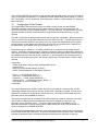
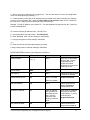
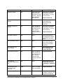
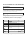
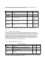
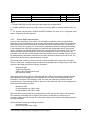
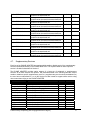
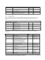
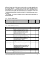
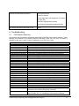
The table below lists the most commonly accepted, de-facto standards used when implementing a
VoIP signaling scheme based on the type of gateway or endpoint equipment being deployed:
VoIP Equipment Type
Typical Port Density
De-Facto Signaling Standards
Trunking Gateways
Greater Than 500 Ports
H.248-Megaco / MGCP / IPDC
Access Gateways
Between five and 500 Ports
SIP / H.323
PBX/KTS Platforms
Between ten and 500 Ports
SIP / H.323 / SCCP
PBX/KTS Telephone Sets
One Port
SIP / MGCP / SCCP
Phone Adapters and IP Centrex
Phones
Up to four Ports
SIP / MGCP
The PHONE ADAPTER supports SIP today. It has the capability to communicate with a variety of
endpoints and signaling entities via SIP messages.
1.2.
1.2.1.
Network Address Translation (NAT) Traversal
What is a NAT or NAPT (Network Address Port Translator)?
A NAT allows multiple devices to share the same external IP address to access the resources on the
external network. The NAT device is usually available as one of the functions performed by a router
that routes packets between an external network and an internal (or private) one. A typical application
of a NAT is to allow all the devices in a subscriber’s home network to access the Internet through a
router with a single public IP address assigned by the ISP. The IP header of the packets sent from
the private network to the public network can be substituted by the NAT with the public IP address
and a port selected by the router according to some algorithm. In other words, recipient of the packets
on the public network will perceive the packets as coming from the external address instead of the
private address of the device where the packets are originated.
In most Internet protocols, the source address of a packet is also used by the recipient as the
destination to send back a response. If the source address of the packets sent from the private
network to the public network is not modified by the router, the recipient may not be able to send back
a response to the originator of the message since its private source IP address/port is not usable.
When a packet is sent from a device on the private network to some address on the external network,
the NAT selects a port at the external interface from which to send the packet to the destination
address/port. The private address/port of the device, the external address/port selected by the NAT to
send the packet, and the external destination address/port of the packet form a NAT Mapping.
The mapping is created when the device first sends a packet from the particular source address/port
to the particular destination address/port and is remembered by the NAT for a short period of time.
This period varies widely from vendor to vendor; it could be a few seconds, or a few minutes, or more,
or less. While the mapping is in effect, packets sent from the same private source address/port to the
same public destination address/port is reused by the NAT. The expiration time of a mapping is
extended whenever a packet is sent from the corresponding source to the corresponding destination.
More importantly, packets sent from that public address/port to the external address/port of the NAT
will be routed back to the private address/port of the mapping session that is in effect. Some NAT
devices actually reuse the same mapping for the same private source address/port to any external IP
address/port and/or will route packets sent to its external address/port of a mapping from any external
© 2004 Linksys Proprietary (See Copyright Notice on Page 2)
15
address/port to the corresponding private source address/port. These characteristics of a NAT can be
exploited by an PHONE ADAPTER to let external entities send SIP messages and RTP packets to it
when it is installed on a private network.
1.2.2.
VoIP-NAT Interworking
In the case of SIP, the addresses where messages/data should be sent to an PHONE ADAPTER are
embedded in the SIP messages sent by the device. If the PHONE ADAPTER is sitting behind a NAT,
the private IP address assigned to it is not usable for communications with the SIP entities outside the
private network. The PHONE ADAPTER must substitute the private IP address information with the
proper external IP address/port in the mapping chosen by the underlying NAT to communicate with a
particular public peer address/port. For this the PHONE ADAPTER needs to perform the following
tasks:
• Discover the NAT mappings used to communicate with the peer. This could be done with
the help of some external device. For example a server could be deployed on the external
network such that the server will respond to a special NAT-Mapping-Discovery request by
sending back a message to the source IP address/port of the request, where the message
will contain the source IP address/port of the original request. The PHONE ADAPTER can
send such a request when it first attempts to communicate with a SIP entity in the public
network and stores the mapping discovery results returned by the server.
• Communicate the NAT mapping information to the external SIP entities. If the entity is a
SIP Registrar, the information should be carried in the Contact header that overwrites the
private address/port information. If the entity is another SIP UA when establishing a call,
the information should be carried in the Contact header as well as in the SDP embedded in
SIP message bodies. The VIA header in outbound SIP requests might also need to be
substituted with the public address if the UAS relies on it to route back responses.
• Extend the discovered NAT mappings by sending keep-alive packets. Since the mapping is
only alive for short period, the PHONE ADAPTER continues to send periodic keep-alive
packets through the mapping to extend its validity as necessary.
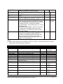
1.3.
Voice Quality Overview
Voice Quality perceived by the subscribers of the IP Telephony service should be indistinguishable
from that of the PSTN. Voice Quality can be measured with such methods as Perceptual Speech
Quality Measurement (PSQM) (1-5 – lower is better) and Mean Opinion Score (MOS) (1-5 – higher is
better).
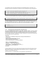
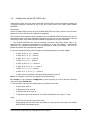
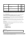
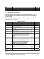
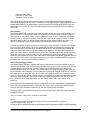
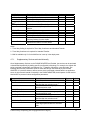
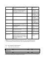
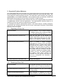
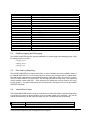
The table below displays speech quality metrics associated with various audio compression
algorithms:
Algorithm
Bandwidth
Complexity
MOS Score
G.711
64 kbps
Very Low
4.5
G.726
16, 24, 32, 40 kbps
Low
4.1 (32 kbps)
G.729a
8 kbps
Low - Medium
4
G.729
8 kbps
Medium
4
G.723.1
6.3, 5.3 kbps
High
3.8
Please note: The PHONE ADAPTER supports all the above voice coding algorithms.
© 2004 Linksys Proprietary (See Copyright Notice on Page 2)
16
Several factors that contribute to Voice Quality are described below.
Audio compression algorithm – Speech signals are sampled, quantized and compressed before they
are packetized and transmitted to the other end. For IP Telephony, speech signals are usually
sampled at 8000 samples per second with 12-16 bits per sample. The compression algorithm plays a
large role in determining the Voice Quality of the reconstructed speech signal at the other end. The
PHONE ADAPTER supports the most popular audio compression algorithms for IP Telephony: G.711
a-law and µ-law, G.726, G.729a and G.723.1.
The encoder and decoder pair in a compression algorithm is known as a codec. The compression
ratio of a codec is expressed in terms of the bit rate of the compressed speech. The lower the bit rate,
the smaller the bandwidth required to transmit the audio packets. Voice Quality is usually lower with
lower bit rate, however. But Voice Quality is usually higher as the complexity of the codec gets higher
at the same bit rate.
Silence Suppression – The PHONE ADAPTER applies silence suppression so that silence packets
are not sent to the other end in order to conserve more transmission bandwidth; instead a noise level
measurement can be sent periodically during silence suppressed intervals so that the other end can
generate artificial comfort noise that mimics the noise at the other end (using a CNG or comfort noise
generator).
Packet Loss – Audio packets are transported by UDP which does not guarantee the delivery of the
packets. Packets may be lost or contain errors which can lead to audio sample drop-outs and
distortions and lowers the perceived Voice Quality. The PHONE ADAPTER applies an error
concealment algorithm to alleviate the effect of packet loss.
Network Jitter – The IP network can induce varying delay of the received packets. The RTP receiver
in the PHONE ADAPTER keeps a reserve of samples in order to absorb the network jitter, instead of
playing out all the samples as soon as they arrive. This reserve is known as a jitter buffer. The bigger
the jitter buffer, the more jitter it can absorb, but this also introduces bigger delay. Therefore the jitter
buffer size should be kept to a relatively small size whenever possible. If jitter buffer size is too small,
then many late packets may be considered as lost and thus lowers the Voice Quality. The PHONE
ADAPTER can dynamically adjust the size of the jitter buffer according to the network conditions that
exist during a call.
Echo – Impedance mismatch between the telephone and the IP Telephony gateway phone port can
lead to near-end echo. The PHONE ADAPTER has a near end echo canceller with at least 8 ms tail
length to compensate for impedance match. The PHONE ADAPTER also implements an echo
suppressor with comfort noise generator (CNG) so that any residual echo will not be noticeable.
Hardware Noise – Certain levels of noise can be coupled into the conversational audio signals due to
the hardware design. The source can be ambient noise or 60Hz noise from the power adaptor. The
PHONE ADAPTER hardware design minimizes noise coupling.
End-to-End Delay – End-to-end delay does not affect Voice Quality directly but is an important factor
in determining whether subscribers can interact normally in a conversation taking place over an IP
network. Reasonable delay figure should be about 50-100ms. End-to-end delay larger than 300ms is
unacceptable to most callers. The PHONE ADAPTER supports end-to-end delays well within
acceptable thresholds.
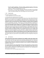
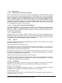
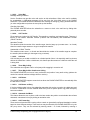
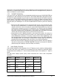
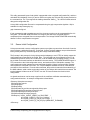
2. Hardware Overview
The PHONE ADAPTER has one of the smallest form factors on the market. It can be installed in
minutes as a table-top or wall mount CPE device. Figures Figure 2 and Figure 3 show the front and
rear, of the PHONE ADAPTER, respectively. Figures 4 and 5 show the front and rear, of the RT31P2
Broadband Router, respectively.
© 2004 Linksys Proprietary (See Copyright Notice on Page 2)
17
Figure 3 – PAP2 Back
Figure 2 – PAP2 Front
Figure 3 – RT31P2 Front
Figure 4 – RT31P2 Back
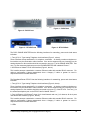
The PAP2 PHONE ADAPTER has the following interfaces for networking, power and visual status
indication:
1. Two (2) RJ-11 Type Analog Telephone Jack Interfaces (Figure 3 , above):
These interfaces accept standard RJ-11 telephone connectors. An Analog touchtone telephone or
fax machine may be connected to either interface. If the service supports only one incoming line, the
analog telephone or fax machine should be connected to port one (1) of the PHONE ADAPTER. Port
one (1) is the outermost telephone port on the PHONE ADAPTER and is labeled “Phone 1.”
2. One Ethernet 10baseT RJ-45 Jack Interface (Figure 3, above):
This interface accepts a standard or crossover Ethernet cable with standard RJ-45 connector. For
optimum performance, Linksys recommends that a Category 5 cable or greater be used in
conjunction with the PHONE ADAPTER.
The Broadband Router RT31P2 has the following interfaces for networking, power and visual status
indication:
1. Two (2) RJ-11 Type Analog Telephone Jack Interfaces (Figure 4, above):
These interfaces accept standard RJ-11 telephone connectors. An Analog touchtone telephone or
fax machine may be connected to either interface. If the service supports only one incoming line, the
analog telephone or fax machine should be connected to port one (1) of the RT31P2. Port one (1) is
the outermost telephone port on the RT31P2 and is labeled “Phone 1.”
2. Four (4) Ethernet 10/100 baseT, three (3) for Local Network and one (1) for Internet, all the 4 ports
uses RJ-45 Jack Interface, (Figure 5, above):
This interface accepts a standard or crossover Ethernet cable with standard RJ-45 connector. For
optimum performance, Linksys recommends that a Category 5 cable or greater be used in
conjunction with the PHONE ADAPTER.
3. LEDs
© 2004 Linksys Proprietary (See Copyright Notice on Page 2)
18
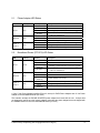
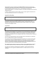
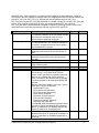
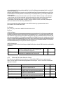
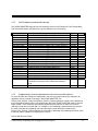
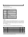
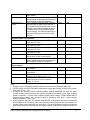
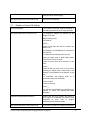
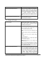
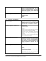
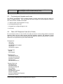
2.1.
Phone Adapter LED Status
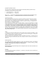
LED
Color(s)
Power
Blue
Ethernet
Blue
Phone 1 /
Phone 2
Blue
2.2.
Activity
Description
Off
Power OFF
Blue On
Power On / Device Ready
Blue Blinking
Booting / System Self-Test / Firmware upgrade
POST (Power On Self Test) failure (not bootable)
Red On
or Device malfunction
Off
No Connection on Ethernet
Blue On
Ethernet Connection established
Blue Blinking
Data Sending / Receiving
Off
Phone is not in use/not provisioned or registered
Blue On
Registered/provisioned
Blue Blinking
Phone is in use/Incoming Call detected
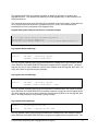
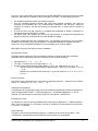
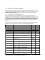
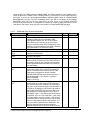
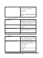
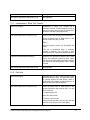
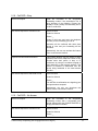
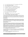
Broadband Router (RT31P2) LED Status
LED
Power
Color(s)
Green
Activity
Off
Solid Green
Green
Blinking
Red On
Ethernet
Phone 1 /
Phone 2
Blue
Blue
Off
Solid Green
Green
Blinking
Off
Green On
Green
Blinking
Description
Power OFF
Power On
Booting / System Self-Test / Firmware upgrade
POST (Power On Self Test) failure (not bootable)
or Device malfunction
No Connection on Ethernet
Ethernet Connection established
Data Sending / Receiving
Phone is not in use/not provisioned or registered
Registered/provisioned
Phone is in use/Incoming Call detected
4. One 5 Volt Power Adapter Interface (Figure 3, above) for PAP2 Phone Adapter and 12 Volt Power
Adapter for the Broadband Router (RT31P2)
This interface accepts the PHONE ADAPTER power adapter that came with the unit. Linksys does
not support the use of any other power adapters other then the power adapter that was shipped with
the PHONE ADAPTER unit or the Broadband Router (RT31P2)
© 2004 Linksys Proprietary (See Copyright Notice on Page 2)
19
Please check to make sure that you have the following package contents:
1.
2.
3.
4.
Linksys Phone Adapter Unit or Linksys Broadband Router (RT31P2)
Ethernet Cable
5 Volt (PAP2) or 12 Volt (RT31P2) Power Adapter
CD with User Guide
You will also need:
1. One or Two Analog Touch Tone Telephones (or Fax Machine)
2. Access to an IP Network via an Ethernet Connection
3. One or Two RJ-11 Phone Cable(s).
Please observe the following steps to install the PHONE ADAPTER. From the rear Side of the
PHONE ADAPTER:
1. Insert a standard RJ-45 Ethernet cable (included) into the LAN port.2. Insert the power
adapter cable into the 5V power adapter cable receptacle. Ensure that the power adapter
jack is snugly attached to the PHONE ADAPTER.
2. Insert a standard RJ-11 telephone cable into the Phone 1 port.2. Connect the other end of
the cable to an analog telephone or fax machine.
3. Insert a standard RJ-11 telephone cable into the Phone 2 port (Optional)
4. Connect the other end of the cable to an analog telephone or fax machine.
Note: Do not connect RJ-11 telephone cable from the PHONE ADAPTER to the wall jack to prevent
any chance of connection to the circuit switched Telco network. You may now insert the plug end of
the power adapter into a live power outlet which will power up the PHONE ADAPTER.
3. Software Configuration Mechanisms
The PHONE ADAPTER provides for secure remote provisioning and remote upgrade. Linksys
recommends that providers use a secure first-time provisioning mechanism using HTTPS (described
in more detail in section 3.2). Subsequent, provisioning is achieved through configuration profiles
transferred to the device via TFTP, HTTP or HTTPS. These configuration profiles can be encrypted
using AES 256-bit symmetric key encryption using a key configured into the device during the initial
HTTPS provisioning stage. As an alternative method for initial configuration, an unprovisioned
PHONE ADAPTER can receive an encrypted profile specifically targeted for that device without
requiring an explicit key, although this is not as secure as using HTTPS.
The PHONE ADAPTER can be configured to resync its internal configuration state to a remote profile
periodically and on power up. An administrator can also remotely trigger a profile resync by sending
an authenticated SIP NOTIFY request to the PHONE ADAPTER.
Likewise, remote upgrades are achieved via TFTP, HTTP or HTTPS. The PHONE ADAPTER
upgrade logic is capable of automating multi-stage upgrades, in case intermediate upgrades are ever
required to reach a future upgrade state from an older release.
General purpose parameters are provided as an additional aid to service providers in managing the
provisioning process. The administrator can configure simple comparisons, translations,
concatenations, and parameter substitution with the aid of these parameters.
All profile resyncs are attempted only when the PHONE ADAPTER is idle, since they may trigger a
software reboot. User intervention is not required to initiate or complete a profile update or firmware
upgrade. In general, most configuration changes take effect without requiring a reboot.
© 2004 Linksys Proprietary (See Copyright Notice on Page 2)
20
The PHONE ADAPTER also provides a Web Interface with two-level access (user-level and adminlevel) to configuration parameters. For standalone PHONE ADAPTERS (which contain no router or
NAT functionality), an IVR (Interactive Voice Response) interface is also available for configuring
basic networking.
3.1.
Configuration Profile Formats
The PHONE ADAPTER configuration profile is an XML or binary file with encoded PHONE
ADAPTER parameter values and optionally user access permissions for those parameters. By
convention, the profile is named with the extension “.cfg” (e.g. pap2.cfg). An administrator can easily
generate the XML format and compress and/or encrypt this file with off-the-shelf tools (e.g. gzip,
openssl).
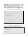
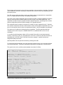
The XML configuration file always begins with the top-level element <flat-profile>. Within this element
are any number of the configuration elements which are visible in the GUI. The XML tag names are
case-sensitive and are identical to the names in the GUI, except that characters other than hyphen,
period, underscore, and alphanumeric characters from the GUI are replaced with an underscore in
the XML names. For example, User ID(1) becomes <User_ID_1_> .
Empty elements (ex: <element/> ) or missing elements do not change the value already stored in
memory. An opening and closing tag (ex: <element></element>) with no included value, deletes the
value stored in memory. Standard XML comments and arbitrary whitespace can be included in the file
for readability purposes. Note that in XML, less-than ("<") and ampersand ("&") characters within an
element must be escaped (using "<" and "&" respectively). Element names in XML are casesensitive.
<flat-profile>
<Profile_Rule>https://config.provider.net/linksys/$MA-cfg.xml
</Profile_Rule>
<Resync_Periodic>86400</Resync_Periodic>
<Admin_Passwd>9b4cef5677a129</Admin_Passwd>
<Proxy_1_>sip.provider.net</Proxy_1_>
<User_ID_1_>1234567890</User_ID_1_>
<Password_1_>YhJ89_Luk4E</Password_1_>
<Display_Name_1_>1234567890</Display_Name_1_>
<Line_Enable_2_>0</Line_Enable_2_>
</flat-profile>
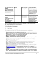
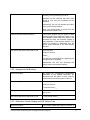
The Linksys Supplementary Profile Compiler tool (SPC) is provided for compiling a plain-text file
containing parameter-value pairs into a binary cfg file which is optionally encrypted. The spc tool is
available from Linksys for the Win32 environment (spc.exe), Linux-i386-elf environment (spc-linuxi386-static) and for the OpenBSD environment.
The syntax of the plain-text file accepted by the profile compiler is a series of parameter-value pairs,
with the value in double quotes. Each parameter-value pair is followed by a semicolon, e.g.
parameter_name “parameter_value”;. If no quoted value is specified for a parameter (or if a
parameter specification is missing entirely from the plain-text file) the value of the parameter will
remain unchanged in the PHONE ADAPTER.
The SPC syntax also controls the parameter’s user-level access when using the built-in web interface
to the PHONE ADAPTER (PAP2-only). An optional exclamation point or question mark, immediately
following the parameter name, indicates the parameter should be user read-write or read-only,
© 2004 Linksys Proprietary (See Copyright Notice on Page 2)
21
respectively. If neither mark is present, the parameter is made inaccessible to the user from the web
interface. Note that this syntax has no effect on the admin-level access to the parameters.
When using the SPC, a service provider is given full control over which parameters become
inaccessible, read-only, or read-write following provisioning of the PHONE ADAPTER.
If the parameter specification is missing entirely from the plain-text file, the user-level access to the
parameter will remain unchanged in the PHONE ADAPTER. If the plain-text file contains multiple
occurrences of the same parameter-value specification, the last such occurrence overrides any
earlier ones.
Parameter names in the plain-text file must match the corresponding names appearing in the PHONE
ADAPTER web interface, with the following modifications:
• Inter-word spaces are replaced by underscores ‘_’ (e.g. Multi_Word_Parameter).
• For the PHONE ADAPTER, line and user specific parameters use bracketed index syntax to
identify which line or user they refer to (e.g. Line_Enable[1] and Line_Enable[2]).
Comments are delimited by a ‘#’ character up to the end-of-line. Blank lines can be used for
readability.
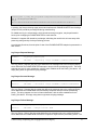
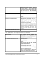
Parameter_name [ ‘?’ | ‘!’ ] [“quoted_parameter_value_string”] ‘;’
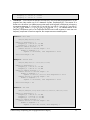
Example of plain-text file entries:
# These parameters are for illustration only
Feature_Enable
Another_Parameter
Hidden_Parameter
! “Enable” ;
? “3600”
;
“abc123” ;
Some_Entry
! ;
# user read-write
# user read-only
# user not-accessible
# user read-write, leave value unchanged
Multiple plain text files can be spliced together to generate the source for each CFG file. This is
accomplished by the “import” directive: the literal string “import” (placed at the start of a new line)
followed by one or more spaces and the file name to splice into the stream of parameter-value pairs.
The following example illustrates. File splicing can be nested several files deep.
# base.txt contains . . .
Param1 “base value 1” ;
Param2 “base value 2” ;
. . .
# Phone Adapter1234.txt contains . . .
import base.txt
Param1 “new value overrides base” ;
Param7 “particular value 7” ;
. . .
© 2004 Linksys Proprietary (See Copyright Notice on Page 2)
22
# The Phone Adapter1234.txt file above is equivalent to . . .
Param1 “base value 1” ;
Param2 “base value 2” ;
. . .
Param1 “new value overrides base” ;
Param7 “particular value 7” ;
. . .
A sample plain-text file, containing default parameter-value and access settings for the PHONE
ADAPTER can be obtained from the profile compiler tool, using the following command-line
arguments.
spc –-sample-profile defaults.txt
In both the XML and SPC configuration formats,] Boolean parameter values that evaluate to true are
any one of the values {Yes | yes | Enable | enable | 1}. Boolean values that evaluate to false are any
one of the values {No | no | Disable | disable | 0}.
3.1.1.
Using the Supplemental Profile Compiler
Once a plain-text file has been generated with the desired parameter settings, it needs to be compiled
into a binary CFG file. The profile compiler can generate a generic unencrypted CFG file, a targeted
CFG file (encrypted for a unique PHONE ADAPTER), a generic key encrypted CFG file, or a targeted
and key encrypted CFG file.
A generic CFG file (non-targeted) is accepted as valid by any PHONE ADAPTER device. A targeted
CFG file is only accepted as valid by the PHONE ADAPTER device bearing the target MAC address.
Targeted CFG files are encrypted with a 128-bit algorithmically generated key, and therefore do not
require a key to be issued explicitly. Targeted CFG files provide a basic level of security for remotely
locking an otherwise unprovisioned PHONE ADAPTER.
The binary configuration format supports RC4 and AES symmetric key algorithms, with keys of up to
256 bits. The key can be specified explicitly as a hex-string, or it can be generated from a password
or a quoted pass-phrase. In the case of passwords and pass-phrases, the internally generated key is
128 bits in length.
The following command-line syntax generates a generic and unencrypted CFG file:
spc pap2.txt pap2.cfg
A targeted CFG file (with basic encryption) is specified by supplying the MAC address of the target
device:
spc –-target 000e08aaa010 pap2.txt pap2.cfg
© 2004 Linksys Proprietary (See Copyright Notice on Page 2)
23
An encrypted CFG file requires either a password (or quoted pass-phrase) or a hex-string. The
following lines illustrate command-line invocations for various combinations of keys and algorithms.
spc
spc
spc
spc
–-rc4
–-aes
–-aes
–-aes
–-ascii-key apple4sale pap2.txt pap2.cfg
–-ascii-key lucky777 pap2.txt pap2.cfg
–-ascii-key “my secret phrase” pap2.txt pap2.cfg
–-hex-key 8d23fe7...a5c29 pap2.txt pap2.cfg
A CFG file can be both targeted and key encrypted, as suggested by the following example:
spc –-target 000e08aaa010 –-aes –-hex-key 9a20...eb47 a.txt a.cfg
The status messages printed by spc can be suppressed with the “--quiet” command line option. Or
they can be redirected to a file, with the “--log file_name” command line option. In the latter case, the
spc command line invocation itself is also printed in the log file, preceded by a timestamp.
spc –-quiet . . .
spc –-log prov.log . . .
3.1.2.
Encrypting and Compressing XML configuration files
The Linksys PHONE ADAPTER supports encrypted XML configuration profiles. This can be used for
subsequent configuration files stored on or generated by either TFTP or HTTP servers. When used
in concert with HTTPS for initial config, this provides complete security, but only uses the HTTPS
server for initial enrollment. For example, an example configuration file in XML setup to download an
encrypted XML file via HTTP looks like this:
<flat-profile>
<Profile_Rule>[--key $B] http://config.provider.net/linksys/established/$MA.xml
</Profile_Rule>
<Resync_Periodic>86400</Resync_Periodic>
<GPP_B >9b4cef5677a129</GPP_B>
<Admin_Passwd>9b4cef5677a129</Admin_Passwd>
<Proxy_1_>sip.provider.net</Proxy_1_>
<User_ID_1_>1234567890</User_ID_1_>
<Password_1_>YhJ89_Luk4E</Password_1_>
<Display_Name_1_>1234567890</Display_Name_1_>
<Line_Enable_2_>0</Line_Enable_2_>
</flat-profile>
An XML configuration file can be encrypted using the openssl command line utility as shown below.
(Note that aes encryption is available beginning with OpenSSL versions 0.9.7. OpenSSL is freely
available from http://www.openssl.org )
openssl aes-256-cbc -e -in cleartextconfig -out encryptedconfig -k 9b4cef5677a129
© 2004 Linksys Proprietary (See Copyright Notice on Page 2)
24
This utility generates 8-bytes of salt (which is prepended to the encrypted configuration file), and then
calculates an Initialization Vector (IV) and an 256-bit encryption key using the key phrase provided on
the command line. The TA recognizes the leading characters "Salted__" as a hint to find the salt and
decrypt the configuration file.
Linksys XML configuration files can be compressed using the gzip compression algorithm. Gzip is
available from http://www.gzip.org .
gzip cleartextconfig.xml
If both compression and encryption are used, the clear text version must be compressed before it is
encrypted. The PHONE ADAPTER does not recognize files which are encrypted and then
compressed since encrypted files are uncompressible. The Linksys PHONE ADAPTER automatically
detects if a file is compressed or encrypted.
3.2.
Secure Initial Configuration
Linksys recommends a secure configuration system to providers to protect them from theft of service,
account forgery, and denial of service. To that end, Linksys Terminal Adapters are provisioned at the
factory with a public key certificate signed by the Linksys certificate authority.
The first step in this process is for the Linksys terminal adapters to use HTTPS to initially contact the
configuration server specified in the Profile_Rule. The initial URL can be configured into the TA at
manufacturing time for order over a certain size, it can be added during a staging process, or it can
be provided via the web interface as described in the next section. The PHONE ADAPTER opens a
TCP connection to the initial configuration server, and sends an SSLv2 ClientHello message. The
configuration server then presents a server certificate signed by Linksys in a ServerHello message,
and requests the certificate of the client. The Terminal Adapter validates the server certificate and
provides its client certificate. From the client certificate, the provider is assured of the authenticity of
the MAC address, serial number, and model number of the Linksys device which has connected. The
terminal adapter will then use an HTTP GET over this TLS secure channel to fetch its initial
configuration.
An Apache web server can be setup to perform all the certificate verification automatically as
configuration directives. An example configuration is listed below:
<Directory /linksys/secure-setup/>
SSLVerifyClient require
SSLVerifyDepth 1
SSLRequireSSL
SSLCertificateFile provider-cert-signed-by-linksys.pem
SSLCertificateKeyFile provider-private-key.pem
SSLCertificateChainFile linksys-cert.pem
SSLCACertificateFile linksys-cert.pem
SSLRequire ( %{SSL_CLIENT_VERIFY} eq "SUCCESS" \
and %{SSL_CLIENT_I_DN_O} eq "Linksys" \
and %{SSL_CLIENT_S_DN_O} eq "Linksys" \
and %{SSL_CLIENT_S_DN_CN} eq %{REQUEST_FILENAME}
</Directory>
© 2004 Linksys Proprietary (See Copyright Notice on Page 2)
25
Within this directory, the Apache module mod_ssl verifies the client certificate, and verifies that the
MAC address in the certificate corresponds the configuration file it is requesting. Either this directory
must contain a configuration file, or a CGI application needs to generate the appropriate config file if
that MAC address is configured in your system. (The Apache web server is freely available at
http://www.apache.org ).
Once an initial XML configuration file is downloaded from the provider web server, subsequent
configuration can be downloaded from the same server. Alternatively, the individual configuration
files can be encrypted using AES 256-bit encryption as described previously, using a key that was
conveyed in the initial configuration file. These encrypted configuration files then can be downloaded
safely using HTTP or TFTP.
Linksys recommends using an encrypted configuration file. In the unlikely event that the private key of
a terminal adapter or the Linksys certificate authority is compromised, terminal adapters which have
already enrolled with a provider and use an encrypted configuration file would be unaffected by such
a compromise.
3.3.
Web Interface
The PHONE ADAPTER provides a built-in web server. Configuration and administration can be
performed through this convenient web interface.
3.3.1.
Web Interface Conventions
The PHONE ADAPTER line uses the following conventions with the web administration capabilities:
o
o
The PHONE ADAPTER web administration supports two privilege levels: Administrator and
User. To use the User privilege, simply point a web browser at the IP address of the PHONE
ADAPTER; to use the administrator privilege, use this URL for the PAP2
http://IP_Address_Of_PHONE ADAPTER/admin/, and this URL for the RT31P2:
http://IP_Address_Of_PHONE ADAPTER/Voice_adminPage.htm . The default IP address for
the LAN interface of the RT31P2 is 192.168.15.1. See the next section for more information
about administration privileges.
o
The PHONE ADAPTER supports Internet Explorer 5.5 and above and Netscape 7.0 and
above.
o
The web configuration pages can be password protected. See 3.3.2 for more information
about password protect.
o
The user name of web Administrator is : admin
o
The user name of web User is : user
o
Note: The user names for both administrator and User are fixed and cannot be changed.
o
After making changes to PHONE ADAPTER configuration parameters, pressing “Submit All
Changes” button will apply all the changes and if necessary, automatically reboot the device.
Multiple changes may be made on multiple page tabs of the web interface at the same time.
Pressing “Submit All Changes” will apply all the modifications.
Important Note: switching between page tabs won’t apply the changes to PHONE
ADAPTER, The only way to apply the changes is to press the “Submit All Changes” button.
If the “Undo All Changes” button is clicked, any modifications to profile parameters on any and
all pages will be reset back to their original values before modification.
© 2004 Linksys Proprietary (See Copyright Notice on Page 2)
26
NOTE: Pressing the “Undo All Changes” has no effect on the PHONE ADAPTER; it will only
reset the values on the web page.
3.3.2.
Administration Privileges
The PHONE ADAPTER supports two levels of administration privileges: Administrator and User, both
privileges can be password protected. Important note: by factory default, there are no passwords
assigned for both Administrator and User.
The Administrator has the privilege to modify all the web profile parameters and can also modify the
passwords of both Administrator and User. A User only has the privilege to access part of the web
profile parameters; the parameter group that User can access is specified by the Administrator, which
can only be done through provisioning.
To access the Administrator level privilege, use the URL for your model number as described in the
previous section. If the password has been set for Administrator, the browser will prompt for
authentication. The username for Administrator is “admin” and cannot be changed.
To access the User level privilege, use URL: http://IP_Address_Of_PHONE ADAPTER/. If the
password has been set for User, the browser will prompt for User authentication. The username for
User is “user” and cannot be changed.
When browsing Administrator pages, one can switch to User privileges by click the link “User Login”.
(Note: if User password was set, the browser will prompt for User authentication when you click “User
Login” link). On the other side, from the User pages you can switch to Administrator privilege by
clicking the link “Admin Login.” Authentication is needed if Administrator password has been set.
Warning: Switching between the User and Administrator will discard the uncommitted changes that
have already been made on the web pages.
3.3.3.
Basic and Advanced Views
The PAP2 web configuration interface provides a Basic and an advanced view from which the various
configuration parameters can be accessed. The PHONE ADAPTER Provisioning tab is only visible
from the Advanced Administrator view of the web interface.
Warning: Switching between the basic and advanced view will discard the uncommitted changes that
have already been made on the web pages.
3.4.
Functional Configuration URLs
The web interface of the PHONE ADAPTER supports several functions through special URLs:
Upgrade, Reboot, Profile Resync, and Factory Reset. Administrator privilege is needed for these
functions.
Note that on the RT31P2, these URLs are only accessible from the LAN interface, unless the
Admin_Passwd has been set and the Enable_Web_Admin_Access parameter is set.
3.4.1.
Upgrade URL
Through upgrade URL you can upgrade the PHONE ADAPTER to a firmware specified by the URL.
Note: If the value of “upgrade enable” parameter in Provisioning tab is no, you cannot upgrade the
PHONE ADAPTER even if the web page tells you that the upgrade will be done when it is not in use.
See 4.2.1 to get more information on firmware upgrade.
The syntax of Upgrade URL is:
http://<PAP2-ip-addr>/upgrade?[protocol://][server-name[:port]][/firmware-pathname] or
© 2004 Linksys Proprietary (See Copyright Notice on Page 2)
27
http://<PAP2-ip-addr>/admin/upgrade?[protocol://][server-name[:port]][/firmware-pathname]
If no protocol is specified, TFTP is assumed. Note: Only TFTP is supported in the current release.
If no server-name is specified, the host that requests the URL is used as server-name.
If no port specified, default port of the protocol is used. (69 for TFTP, 80 for http, 443 for HTTPS)
The “firmware-pathname” is typically the file name of the PHONE ADAPTER binary located in the root
directory of the TFTP server. If no firmware-pathname is specified, “/Phone Adapter.bin” is assumed.
For example: http://192.168.2.217/upgrade?tftp://192.168.2.251/PAP2.bin
3.4.2.
Resync URL
Through Resync URL you can force the PHONE ADAPTER to do a resync to a profile specified in the
URL.
Note: The PHONE ADAPTER will resync only when it is idle.
The syntax of Resync URL is:
http://<Phone Adapter-ip-addr>/resync?[[protocol://][server-name[:port]]/profile-pathname]
If no parameter follows “/resync?”, the profile rule setting in provisioning is used. See 4.2 for detailed
information about profile rule in provisioning
If no protocol is specified, TFTP protocol is assumed. Note: Only TFTP is supported in the current
release.
If no server-name is specified, the host that requests the URL is used as server-name.
If no port specified, default port of the protocol is used – 69 for TFTP, 80 for http, 443 for HTTPS.
The profile-path is the path to the new profile to resync with.
For example: http://192.168.2.217/upgrade?tftp://192.168.2.251/PAP2.scf
3.4.3.
Reboot URL
Through the Reboot URL, you can reboot the PHONE ADAPTER.
Note: Upon request, the PHONE ADAPTER will reboot only when it is idle.
The Reboot URL is: http://<Phone Adapter-ip-addr>/admin/reboot
3.4.4.
Factory Reset URL
Through the Reset URL, you can perform a factory reset of the PHONE ADAPTER.
Note: Upon request, the PHONE ADAPTER will reset and then reboot only when it is idle.
The Reset URL is: http://<Phone Adapter-ip-addr>/admin/reset
© 2004 Linksys Proprietary (See Copyright Notice on Page 2)
28
3.5.
Configuration via the IVR (PAP2 only)
Administrators and/or users can check (read) and set (write) basic network configuration settings via
a touchtone telephone connected to one of the RJ-11 phone ports of the PAP2 model PHONE
ADAPTER.
Please Note:
Service Providers offering service using the PHONE ADAPTER may restrict, protect or turn off certain
aspects of the unit’s IVR and web configuration capabilities.
The Interactive Voice Response (IVR) capabilities of the PHONE ADAPTER are designed to give the
administrator and/or user basic read/write capabilities such that the unit can attain basic IP network
connectivity and the more advanced browser-based configuration menu may be accessed.
1. The PHONE ADAPTER IVR uses the following conventions: By factory default there is no
password and no password authentication is prompted for all the IVR settings. If administrator
password is set, password authentication will be prompted for certain IVR settings. See 3.4.2 for
detailed information about administrator password.
To input the password using the phone keypad, the following translation convention applies:
o
To input: A, B, C, a, b, c -- press ‘2’
o
To input: D, E, F, d, e, f -- press ‘3’
o
To input: G, H, I, g, h, i -- press ‘4’
o
To input: J, K, L, j, k, l -- press ‘5’
o
To input: M, N, O, m, n, o -- press ‘6’
o
To input: P, Q, R, S, p, q, r, s -- press ‘7’
o
To input: T, U, V, t, u, v -- press ‘8’
o
To input: W, X, Y, Z, w, x, y, z -- press ‘9’
o
To input all other characters in the administrator password, press ‘0’
Note: This translation convention only applies to the password input.
For example: to input password “test#@1234” by phone keypad, you need to press the following
sequence of digits: 8378001234.
2. After entering a value, press the # (pound) key to indicate end of input.
o
To Save value, press ‘1’
o
To Review the value, press ‘2’
o
To Re-enter the value, press ‘3’
o
To Cancel the value entry and return to the main configuration menu, press ‘*’ (star)
Notes:
o
The final ‘#’ key won’t be counted into value.
o
Saved settings will take effect when the telephone is hung-up and if necessary, the PHONE
ADAPTER will automatically reboot.
© 2004 Linksys Proprietary (See Copyright Notice on Page 2)
29
3. After one minute of inactivity, the unit times out. The user will need to re-enter the configuration
menu from the beginning by pressing * * * *.
4. If, while entering a value (like an IP address) and you decide to exit without entering any changes,
you may do so by pressing the * (star) key twice within a half second window of time. Otherwise,
the entry of the * (star) key will be treated as a dot (decimal point).
Example: To enter IP address, use numbers 0 – 9 on the telephone key pad and use the * (star) key
to enter a decimal point.
To enter the following IP address value: 192.168.2.215
A. Use the touchtone key pad to enter: 192*168*2*215#
B. When prompted, enter 1 to save setting to configuration.
C. Hang-up the phone to cause setting to take effect.
- or D. Enter the value of the next setting category to modify . . .
5. Hang-up the phone to cause all settings to take effect.
PHONE ADAPTER Interactive Voice Response (IVR) Menu:
IVR Action
IVR Menu Choice
Enter IVR Menu
Parameter(s)
Notes:
None
Ignore SIT or other tones
until you hear, “Linksys
configuration menu.
Please enter option
followed by the pound key
or hang-up to exit.”
****
Exit IVR Menu
3948
None
Check DHCP
100
None
IVR will announce if DHCP
in enabled or disabled.
Enable/Disable DHCP
101
Enter 1 to enable
Requires Password
Enter 0 to disable
Check IP Address
110
None
IVR will announce the
current IP address of
PHONE ADAPTER.
Set Static IP Address
111
Enter IP address
using numbers on
the telephone key
pad. Use the *
(star) key when
entering a decimal
point.
DHCP must be “Disabled”
otherwise you will hear,
“Invalid Option,” if you try
to set this value.
None
IVR will announce the
current network mask of
Check Network Mask
120
© 2004 Linksys Proprietary (See Copyright Notice on Page 2)
Requires Password
30
PHONE ADAPTER.
Set Network Mask
121
Enter value using
numbers on the
telephone key pad.
Use the * (star) key
when entering a
decimal point.
DHCP must be “Disabled”
otherwise you will hear,
“Invalid Option,” if you try
to set this value.
Requires Password
Check Static Gateway IP
Address
130
None
IVR will announce the
current gateway IP
address of PHONE
ADAPTER.
Set Static Gateway IP
Address
131
Enter IP address
using numbers on
the telephone key
pad. Use the *
(star) key when
entering a decimal
point.
DHCP must be “Disabled”
otherwise you will hear,
“Invalid Option,” if you try
to set this value.
Requires Password
Check MAC Address
140
None
IVR will announce the
MAC address of PHONE
ADAPTER in hex string
format.
Check Firmware Version
150
None
IVR will announce the
version of the firmware
running on the PHONE
ADAPTER.
Check Primary DNS
Server Setting
160
None
IVR will announce the
current setting in the
Primary DNS field.
Set Primary DNS Server
161
Enter IP address
using numbers on
the telephone key
pad. Use the *
(star) key when
entering a decimal
point.
Requires Password
Check PHONE
ADAPTER’s Web Server
Port
170
None
IVR will announce the
port that the web server
is listening on. (Default is
80)
Enable/Disable Web
Server of PHONE
ADAPTER
7932
Enter 1 to enable
Enter 0 to disable
Requires Password
Manual Reboot of Unit
732668
None
After you hear “Option
Successful,” hang-up. Unit
will reboot automatically.
© 2004 Linksys Proprietary (See Copyright Notice on Page 2)
31
User Factory Reset of Unit
877778
Enter 1 to confirm
Enter *(star) to
cancel operation
PHONE ADAPTER will
prompt for confirmation.
After confirming, you will
hear “Option Successful.”
Hang-up. Unit will reboot
and all “User Changeable”
configuration parameters
will be reset to factory
default values.
73738
Enter 1 to confirm
Enter * (star) to
cancel operation
PHONE ADAPTER will
prompt for confirmation.
After confirming, you will
hear “Option Successful.”
Hang-up. Unit will reboot
and all configuration
parameters will be reset to
factory default values.
WARNING:
ALL “User-Changeable” NONDEFAULT SETTINGS WILL BE
LOST!
This might include network and
service provider data.
Factory Reset of Unit
WARNING:
ALL NON-DEFAULT SETTINGS
WILL BE LOST!
This includes network and
service provider data.
Note: If the Administrator password is not set or the user is allowed to change it, the items marked
with “Requires Password” will not require a password.
4. Configuration Parameters
4.1.
Data Types
The data types for the PHONE ADAPTER configuration parameters are described below.
•
•
•
•
•
•
•
•
•
•
•
•
•
•
•
Uns<n> – Unsigned n-bit value, where n = 8, 16, or 32. It can be specified in decimal or hex
format such as 12 or 0x18 as long as the value can fit into n bits.
Sig<n> – Signed n-bit value. It can be specified in decimal or hex format. Negative values must
be preceded by a “-“ sign. A ‘+’ sign before positive value is optional
Str<n> – A generic string with up to n non-reserved characters.
Float<n> – A floating point value with up to n decimal places.
Time<n> – Time duration in seconds, with up to n decimal places. Extra decimal places specified
are ignored.
PwrLevel – Power level expressed in dBm with 1 decimal place, such as –13.5 or 1.5 (dBm)
Bool: Boolean value of either “yes” or “no”
{a,b,c,…} – A choice among a, b, c, …
IP – IP Address in the form of x.x.x.x, where x between 0 and 255. For example 10.1.2.100
Port – TCP/UDP Port number (0-65535). It can be specified in decimal of hex format.
UserID – User ID as appeared in a URL; up to 63 characters
FQDN – Fully Qualified Domain Name, such as “sip.Linksys.com:5060”, or “109.12.14.12:12345”.
It can contain up to 63 characters
Phone – A phone number string, such as 14081234567, *69, *72, 345678, or a generic URL such
as [email protected]:5068, or [email protected]. It can contain up to 39 characters.
ActCode – Activation code for a supplementary service, such as *69. It can contain up to 7
characters.
PhTmplt – A phone number template. Each template may contain 1 or more patterns separated
by a “,”. White Phone Adapterce at the beginning of each pattern is ignored. “?” and “*” represent
© 2004 Linksys Proprietary (See Copyright Notice on Page 2)
32
•
•
wildcard characters. It can contain up to 39 characters. Examples: “1408*, 1510*”,
“1408123????, 555?1”.
RscTmplt – A template of SIP Response Status Code, such as “404, 5*”, “61?”, “407, 408, 487,
481”. It can contain up to 39 characters.
CadScript – A mini-script that specifies the cadence parameters of a signal. Up to 127
characters. Syntax: S1[;S2], where
Si=Di(oni,1/offi,1[,oni,2/offi,2[,oni,3/offi,3[,oni,4/offi,4[,oni,5/offi,5[,oni,6/offi,6]]]]]) and is known as a section,
oni,j and offi,j are the on/off duration in seconds of a segment and i = 1 or 2, and j = 1 to 6. Di is the
total duration of the section in seconds. All durations can have up to 3 decimal places to provide 1
ms resolution. The wildcard character “*” stands for infinite duration. The segments within a
section are played in order and repeated until the total duration is played. Examples:
Example 1: Normal Ring
60(2/4)
Number of Cadence Sections = 1
Cadence Section 1: Section Length = 60 s
Number of Segments = 1
Segment 1: On=2s, Off=4s
Total Ring Length = 60s
Example 2: Distinctive Ring (short,short,short,long)
60(.2/.2,.2/.2,.2/.2,1/4)
Number of Cadence Sections = 1
Cadence Section 1: Section Length = 60s
Number of Segments = 4
Segment 1: On=0.2s, Off=0.2s
Segment 2: On=0.2s, Off=0.2s
Segment 3: On=0.2s, Off=0.2s
Segment 4: On=1.0s, Off=4.0s
Total Ring Length = 60s
•
FreqScript – A mini-script that specifics the frequency and level parameters of a tone. Up to 127
characters. Syntax: F1@L1[,F2@L2[,F3@L3[,F4@L4[,F5@L5[,F6@L6]]]]], where F1–F6 are frequency
in Hz (unsigned integers only) and L1–L6 are corresponding levels in dBm (with up to 1 decimal
places). White spaces before and after the comma are allowed (but not recommended)
Example 1: Call Waiting Tone
440@-10
Number of Frequencies = 1
Frequency 2 = 440 Hz at –10 dBm
Example 2: Dial Tone
350@-19,440@-19
© 2004 Linksys Proprietary (See Copyright Notice on Page 2)
33
Number of Frequencies = 2
Frequency 1 = 350 Hz at –19 dBm
Frequency 2 = 440 Hz at –19 dBm
•
ToneScript – A mini-script that specifies the frequency, level and cadence parameters of a call
progress tone. May contain up to 127 characters. Syntax: FreqScript;Z1[;Z2]. The section Zi is
similar to the Si section in a CadScript except that each on/off segment is followed by a frequency
components parameter: Zi = Di(oni,1/offi,1/fi,1[,oni,2/offi,2/fi,2 [,oni,3/offi,3/fi,3 [,oni,4/offi,4/fi,4 [,oni,5/offi,5/fi,5
[,oni,6/offi,6/fi,6]]]]]), where fi,j = n1[+n2]+n3[+n4[+n5[+n6]]]]] and 1 < nk < 6 indicates which of the
frequency components given in the FreqScript shall be used in that segment; if more than one
frequency component is used in a segment, the components are summed together.
Example 1: Dial Tone
350@-19,440@-19;10(*/0/1+2)
Number of Frequencies = 2
Frequency 1 = 350 Hz at –19 dBm
Frequency 2 = 440 Hz at –19 dBm
Number of Cadence Sections = 1
Cadence Section 1: Section Length = 10 s
Number of Segments = 1
Segment 1: On=forever, with Frequencies 1 and 2
Total Tone Length = 10s
Example 2: Stutter Tone
350@-19,440@-19;2(.1/.1/1+2);10(*/0/1+2)
Number of Frequencies = 2
Frequency 1 = 350 Hz at –19 dBm
Frequency 2 = 440 Hz at –19 dBm
Number of Cadence Sections = 2
Cadence Section 1: Section Length = 2s
Number of Segments = 1
Segment 1: On=0.1s, Off=0.1s with Frequencies 1 and 2
Cadence Section 2: Section Length = 10s
Number of Segments = 1
Segment 1: On=forever, with Frequencies 1 and 2
Total Tone Length = 12s
Example 3: SIT Tone
985@-16,1428@-16,1777@-16;20(.380/0/1,.380/0/2,.380/0/3,0/4/0)
Number of Frequencies = 3
Frequency 1 = 985 Hz at –16 dBm
Frequency 2 = 1428 Hz at –16 dBm
Frequency 3 = 1777 Hz at –16 dBm
Number of Cadence Sections = 1
Cadence Section 1: Section Length = 20s
Number of Segments = 4
Segment 1: On=0.38s, Off=0s, with Frequency 1
© 2004 Linksys Proprietary (See Copyright Notice on Page 2)
34
Segment 2: On=0.38s, Off=0s, with Frequency 2
Segment 3: On=0.38s, Off=0s, with Frequency 3
Segment 4: On=0s, Off=4s, with no frequency components
Total Tone Length = 20s
•
•
ProvisioningRuleSyntax – Scripting syntax used to define configuration resync and firmware
upgrade rules. Refer to the provisioning discussion in the next section for a detailed explanation
of the syntax.
DialPlanScript – Scripting syntax used to specify line 1 and line 2 dial plans. Refer to the dial
plan section of this document for a detailed explanation of the syntax.
4.1.1.
Conventions
• <Par Name> represents a configuration parameter name. In a profile, the corresponding
tag is formed by replacing the space with an underscore “_”, such as Par_Name.
• An empty default value field implies an empty string < “” >.
• The PHONE ADAPTER shall continue to use the last configured values for tags that are
not present in a given profile.
• Templates are compared in the order given. The first, not the closest, match is selected.
The parameter name must match exactly.
• If more than one definition for a parameter is given in a configuration file, the last such
definition in the file is the one that will take effect in the PHONE ADAPTER.
• A parameter specification with an empty parameter value forces the parameter back to its
default value. To specify an empty string instead, use the empty string “” as the parameter
value.
4.2.
Provisioning Related Parameters
Provisioning is controlled by the following parameters (firmware upgrades are discussed later in this
section).
•
•
•
•
•
•
•
•
•
•
•
•
•
•
•
•
•
•
Provision_Enable
Resync_On_Reset
Resync_Random_Delay
Resync_Periodic
Resync_Error_Retry_Delay
Forced_Resync_Delay
Resync_From_SIP
Resync_After_Upgrade_Attempt
Resync_Trigger_1
Resync_Trigger_2
Resync_Fails_On_FNF
Profile_Rule
Profile_Rule_B
Profile_Rule_C
Profile_Rule_D
Log_Resync_Request_Msg
Log_Resync_Success_Msg
Log_Resync_Failure_Msg
© 2004 Linksys Proprietary (See Copyright Notice on Page 2)
35
•
•
GPP_A through GPP_P
GPP_SA through GPP_SD
Provision Enable:
ParName:
Provision_Enable
Default:
Enable
The CFG profile must be requested by the PHONE ADAPTER, and cannot be pushed from a
provisioning server (although a service provider can effectively push a profile by triggering the request
operation remotely via a SIP NOTIFY). The functionality is controlled by the Provision_Enable
parameter. The parameter enables the functionality encompassed by the remaining provisioning
parameters.
In addition, Provision_Enable also gates the ability to issue an explicit resync command from the web
interface (discussed earlier in the "Function URLs" section of this document).
Resync on Reset:
ParName:
Resync_On_Reset
Default:
Enable
Resync_On_Reset determines whether the PHONE ADAPTER will attempt to resync with the
provisioning server on power-up and following explicit reboot requests.
Resync Random Delay:
ParName:
Resync_Random_Delay
Default:
2
Resync_Random_Delay helps to scatter resync requests from multiple devices uniformly over a
period of time, whose duration (in seconds) is indicated by this parameter. Hence, if a number of
PHONE ADAPTER devices were to power-up at the same time, their resync requests would be
distributed over time, lessening the impact on the provisioning servers.
Resync Periodic:
ParName:
Resync_Periodic
Default:
3600
The PHONE ADAPTER attempts to resync with the provisioning server periodically, provided the
Resync_Periodic parameter is configured with a non-zero value. The value (in seconds) indicates the
interval between resync attempts. Normally, the PHONE ADAPTER will not start the resync while an
© 2004 Linksys Proprietary (See Copyright Notice on Page 2)
36
active call is in progress. The PHONE ADAPTER will wait up to Forced_Update_Delay seconds for
both lines to become idle. If the adapter still is not idle, the adapter will perform a resync anyway.
Resync Error Retry Delay:
ParName:
Resync_Error_Retry_Delay
Default:
3600
If a resync attempt fails, the PHONE ADAPTER will retry with a delay indicated by the
Resync_Error_Retry_Delay parameter, specified in seconds. If the value is zero, the PHONE
ADAPTER treats resync failures as though they were successful, and simply waits for the next
periodic event to resync.
Resync From SIP:
ParName:
Resync_From_SIP
Default:
Enable
Resync_From_SIP gates the ability of a service provider to trigger a profile resync via a SIP NOTIFY
message to the PHONE ADAPTER.
If the PHONE ADAPTER receives a SIP NOTIFY request with an Event header field value of
"resync", "reboot", or "restart"; the PHONE ADAPTER will attempt to Digest authenticate the notifier
using the authentication password used for registrations on that line if the Auth_Resync-Reboot
parameter is set. If this parameter is not set or if the NOTIFY request is authenticated, the PHONE
ADAPTER triggers a resync, cold-boot, or warm-boot respectively. The actual resync, reboot, or
restart will not take place until the PHONE ADAPTER is idle (i.e. no calls are in progress).
Profile Rule:
ParName:
Profile_Rule
Default:
/spa$PSN.cfg
ParName:
Profile_Rule_B
Default:
Empty
through
Profile_Rule_D
The Profile_Rule parameter is a script that identifies the provisioning server to contact when
performing a profile resync. The Profile_Rule_B, Profile_Rule_C, and Profile_Rule_D parameters are
also scripts used to contact other provisioning URLs. Each profile rule is executed only if the previous
profile rule was executed successfully(*).
© 2004 Linksys Proprietary (See Copyright Notice on Page 2)
37
These strings each supports one level of macro expansion, using a small set of variables. Following
macro substitution, the rule is evaluated to obtain the URL of the CFG file to be requested from the
provisioning server.
The URL can be partially specified, in which case default values are assumed for the unspecified
terms. The filepath portion of the URL must always be specified.
The Profile_Rule supports additional syntax that allows the URL to include conditions, for example
based on a function of the firmware release currently running in the PHONE ADAPTER. This
mechanism can aid the service provider’s firmware upgrade sequence, by allowing them to define
different configuration profiles for different stages of an upgrade sequence.
The conditional syntax consists of a sequence of condition-url pairs, separated by the ‘|’ character.
The condition component tests the current firmware version number against a specified value. If the
last url in the sequence does not have an associated condition, it will be attempted unconditionally.
The sequence of conditions is evaluated until one is satisfied. The URL associated with that
condition is then used to resync the PHONE ADAPTER. No additional URLs in the rule are
considered.
(*) A profile rule which attempts to fetch a URL succeeds if the profile is received and parsed
correctly. If the Resync_Fails_On_FNF parameter is set to No, a profile rule will also succeed if an
attempted fetch for a URL returns a File Not Found error message. A profile rule with only
assignments always succeeds.
Optional qualifiers can be specified in brackets, preceding each URL.
To ease testing and development, the script syntax also supports using ‘#’ as a comment delimiter
(until end-of-parameter). This allows a potentially long script to be temporarily “commented out”.
The syntax for the rule is as follows (with standard conventions for URLs):
rule = term *( "|" term )
term = [condition] [assignments] [options] url
condition = "(" conditionseq ")" "?"
conditionseq = condelem *( conjunction condelem )
condelem = numcond / vercond / strcond
numcond = number relop number
vercond = [ version ] relop version
relop = "<" / "<=" / ">" / ">=" / "==" / "!="
/ "!" / "gt" / "ge" / "lt" / "le" / "eq" / "ne"
version = major "." minor "." build [ "(" features ")" ]
strcond = cond *( conjunction cond )
strcond = qstr eqop qstr
conjunction = "and"
qstr = DQUOT val DQUOT
eqop = "==" / "!=" / "!" / "eq" / "ne"
assignments = "(" *assignment ")" "!"
assignment(*) = attribute "=" expr ";"
© 2004 Linksys Proprietary (See Copyright Notice on Page 2)
38
expr = DQUOT val DQUOT
options = "[" *option "]"
option = key-opt / alias-opt / post-opt
key-opt = "--key" key-string
key-string = password / quoted-pass-phrase / hex-string
alias-opt = "--alias" val
post-opt = "--post" val
url = [ method "://" [ server [":" port]]] "/" *(dir "/") file
method = "tftp" / "http" / "https"
server(**) = ip4quad / fqdn
( * ) Attribute can contain the name of any configuration parameter
( ** ) If the server and scheme are unspecified, the TFTP server name provided by the LAN’s DHCP
server is used instead. Also, an FQDN with multiple DNS entries is multiply resolved by the PHONE
ADAPTER.
The variables available for macro substitution (with example values) are as follows:
PN
PSN
MA
MAU
MAC
SN
SWVER
HWVER
UPGCOND
SCHEME
SERV
SERVIP
PORT
PATH
IP
EXTIP
PAP2
PAP2
000f66aaa010
000F66AAA010
00:0f:66:aa:a0:10
CH500D600862
1.0.2
1.0.1
1.0.2<1.1
tftp
http.example.com
10.2.3.200
69
/guest/pap2.cfg
192.168.1.102
45.73.21.44
PRVST
UPGST
ERR
A to P
SA to SD
0
0
corrupt file
some-value
some-value
Product Name
Product Series Number
MAC Address
MAC Address (upper case)
MAC Addr with Colon separators
Serial Number
Firmware Version Number
Hardware Version Number
Upgrade(*) Condition
Access Scheme
Server Name
Server IP Address
TCP/IP Request Port
File path
IP address of the PHONE ADAPTER
Configured or discovered external IP
address (for example using STUN)
Error Code of Last Profile Rule(**)
Error Code of Last Upgrade Rule(**)
Error/Info(***) message
Contents of GPP_A to GPP_P
Contents of GPP_SA to GPP_SD
( * ) Note that the UPGCOND term is particularly useful in the Upgrade_Rule (discussed later in this
document), but applies equally as a resync condition. It shows which term of the rule triggered the
operation.
( ** ) See section 6.5 for the values of these macro variables.
( *** ) Upon successful firmware upgrade, the ERR variable carries the version of the newly installed
load.
© 2004 Linksys Proprietary (See Copyright Notice on Page 2)
39
In addition, the contents of the general purpose parameters, GPP_A, through GPP_P, are available
as macro variables A through P, respectively.
A secondary set of general purpose parameters is also available for macro substitution, GPP_SA,
GPP_SB, GPP_SC, GPP_SD, using the respective expressions SA, SB, SC, and SD. These
parameters are not accessible through the web interface, and can only be set via a configuration
profile.
Strings identified above as "val" values are strings which can include variable substitution. The macro
variables are invoked by prefixing the name with a ‘$’ character (e.g. $MAC). The substitution works
even within a quoted string, without requiring additional escapes. If the variable name is immediately
followed by an alphanumeric character, enclose the variable name in parentheses (e.g.
"$(MAC)config.xml" ).
To include a dollar sign in the rule, escape it with another dollar sign. That is $$ maps to $.
Profile_Rule syntax examples (each line is a separate example):
/pap2.cfg
pserv.myvoice.com:42000/sip/$MA/pap2.cfg
[--key 6e4f2a8733ba7c90aa13250bde4f6927]ur.well.com/Gj2fLx3Nqbg/a.cfg
(<1.0)?/pre-rel.cfg | /curr.cfg
Profile Example Scenarios:
Enterprise LAN with DHCP Supplied TFTP Server Name:
The DHCP server automatically advertises a TFTP server name to service the local network. Each
PHONE ADAPTER in the network is supplied a unique CFG file based on its MAC address. The
TFTP server would also contain a generic Phone Adapter2000.cfg in its tftp-root directory that
contains the Profile_Rule indicated below. It would additionally carry individualized CFG files, one
per device, within a tree below the tftp-root node. Each of these files would then individualize the
devices.
/profiles/$MA/pap2.cfg
When first powered-on, unprovisioned devices would download the /pap2.cfg file from the TFTP
server indicated by DHCP, (following their manufacturing default setting for the Profile_Rule
parameter). The downloaded file would then direct the PHONE ADAPTER to resync to the server
and fetch the individualized CFG file, as per the rule above, which completes the provisioning
sequence.
VoIP Service Provider:
Conceptually, a service provider solution would follow the steps as in the above example. In addition,
it would then proceed to enable stronger encryption by implementing one more provisioning step, with
one more level of redirection, involving a random CFG file path and encryption key. Hence, each of
the “first-stage” CFG files above would point to a “second-stage” CFG file, with entries such as the
following:
© 2004 Linksys Proprietary (See Copyright Notice on Page 2)
40
Profile_Rule “[--key $B] ps.global.com/profiles/active/$A/pap2.cfg”;
GPP_A “Dz3P2q9sVgx7LmWbvu”;
GPP_B
“83c1e792bc6a824c0d18f429bea52d8483f2a24b32d75bc965d05e38c163d5ef”;
In practice, the first provisioning stage (which individualizes each PHONE ADAPTER into fetching a
unique CFG file) could be preconfigured during manufacturing.
For added security, the second stage, which introduces strong encryption, may be performed inhouse, prior to shipping an PHONE ADAPTER to each end-user.
Release 2.0 supports SSL-based key exchanges, alleviating the need for this in-house step, while
preserving strong security for the provisioning process.
A provisioning flow chart, from the point of view of the PHONE ADAPTER endpoint is presented in a
later section.
Log Resync Request Message:
ParName:
Log_Resync_Request_Msg
Default:
$PN $MAC –- Requesting resync $SCHEME://$SERVIP:$PORT$PATH
The Log_Resync_Request_Msg is a script that defines the message sent to the configured Syslog
server whenever the PHONE ADAPTER attempts to resync with the provisioning server. The string
supports one level of macro substitution, with the same variables as for the Profile_Rule above. An
empty string does not generate a syslog message.
Log Resync Success Message:
ParName:
Log_Resync_Success_Msg
Default:
$PN $MAC –- Successful resync $SCHEME://$SERVIP:$PORT$PATH
The Log_Resync_Success_Msg is a script that defines the message sent to the configured Syslog
server whenever the PHONE ADAPTER successfully completes a resync with the provisioning
server. The string supports one level of macro substitution, with the same variables as for the
Profile_Rule above. An empty string does not generate a syslog message.
Log Resync Failure Message:
ParName:
Log_Resync_Failure_Msg
Default:
$PN $MAC –- Resync failed: $ERR
The Log_Resync_Failure_Msg is a script that defines the message sent to the configured Syslog
server whenever the PHONE ADAPTER fails to complete a resync with the provisioning server. The
© 2004 Linksys Proprietary (See Copyright Notice on Page 2)
41
string supports one level of macro substitution, with the same variables as for the Profile_Rule above.
An empty string does not generate a syslog message.
General Purpose Parameters:
ParName:
GPP_A
Default:
empty
through
GPP_P
GPP_A through GPP_P are the 16 General Purpose Parameters, usable by both the provisioning and
the upgrade logic. Each general purpose parameter can be configured to hold any string value.
Such a value can then be incorporated in other scripted parameters.
General Purpose Secure Parameters:
ParName:
GPP_SA
Default:
empty
through
GPP_SD
GPP_SA through GPP_SD are the 4 Secure General Purpose Parameters, usable by both the
provisioning and the upgrade logic. Each secure parameter can be configured to hold any string
value. Such a value can then be incorporated in other scripted parameters. The secure parameters
are not accessible through the PHONE ADAPTER web interface, and can only be set via a
configuration profile. Also, the parameters cannot be incorporated as part of a syslog message.
Parameter Name
Provision Enable
Resync On Reset
Resync Random
Delay
Resync Periodic
Resync Error Retry
Delay
Resync From SIP
Resync After Upgrade
Attempt
Resync Trigger 1
Resync Trigger 2
Profile Rule
Description
Master enable for configuration profile
resync operations
Resyncs configuration profile from
configuration server whenever the PHONE
ADAPTER resets.
Spread interval for resync requests
Type
Bool
Default
yes
Bool
yes
Time0
2
Resyncs configuration profile periodically
after reset.
Retry interval following resync failure
Time0
3600
Time0
3600
Enables resync of configuration profile from
a SIP command.
Bool
Yes
Bool
Yes
ProfileScript
/Phone
Adapter.cfg
Configuration profile URL script.
Profile Rule B
Profile Rule C
Profile Rule D
© 2004 Linksys Proprietary (See Copyright Notice on Page 2)
ProfileScript
ProfileScript
ProfileScript
42
Log Resync Request
Msg
Syslog message generated when attempting
a resync
ProfileMsg
Log Resync Success
Msg
Syslog message generated after a
successful resync
ProfileMsg
Log Resync Failure
Msg
Syslog message generated after a failed
resync
ProfileMsg
GPP A thru GPP P
GPP SA thru GPP SD
General purpose parameter
General purpose parameter
String
String
See
provisioning
discussion
section
See
provisioning
discussion
section
See
provisioning
discussion
section
empty
empty
Note: In a customized PHONE ADAPTER, the profile rule would point to a service provider’s server.
4.2.1.
Firmware Upgrade
The PHONE ADAPTER is firmware upgradeable via TFTP and HTTP. Firmware loads are released
as single binary files, which contain all the modules pertaining to any one release version. By
convention, the firmware loads are named with the extension “.bin” (e.g. pap2.bin)
The PHONE ADAPTER can be configured to upgrade to a specific version, possibly staging through
intermediate releases, if necessary. This process can be automated for a pool of devices through
configuration profile parameters.
Alternatively, an individual PHONE ADAPTER can be directed to perform an upgrade to a specific
firmware load via its built-in web server interface (this mechanism is discussed in section 3.4.1 of this
document).
Firmware upgrades are attempted only when the PHONE ADAPTER is idle, since they trigger a
software reboot.
Firmware upgrades are controlled by the following parameters (which operate in a manner similar to
but independent of the provisioning parameters).
•
•
•
•
•
•
•
Upgrade_Enable
Upgrade_Error_Retry_Delay
Upgrade_Rule
Downgrade_Rev_Limit
Log_Upgrade_Request_Msg
Log_Upgrade_Success_Msg
Log_Upgrade_Failure_Msg
Upgrade Enable:
ParName:
Upgrade_Enable
Default:
Enable
© 2004 Linksys Proprietary (See Copyright Notice on Page 2)
43
The firmware file must be requested by the PHONE ADAPTER and cannot be pushed from an
upgrade server (although a service provider can effectively push a new firmware load by triggering
the request operation remotely via the CFG file). The functionality is controlled by the
Upgrade_Enable parameter. The parameter enables the functionality encompassed by the remaining
upgrade parameters.
In addition, Upgrade_Enable also gates the ability to issue an explicit upgrade command from the
web interface (discussed in section 3.4.1 of this document).
Upgrade Error Retry Delay:
ParName:
Upgrade_Error_Retry_Delay
Default:
3600
If an upgrade attempt fails, the PHONE ADAPTER will retry with a delay indicated by the
Upgrade_Error_Retry_Delay parameter, specified in seconds. If the value is zero, the PHONE
ADAPTER treats upgrade failures as though they were successful, and will not retry to upgrade
unless some event triggers a reboot.
Upgrade Rule:
ParName:
Upgrade_Rule
Default:
Empty
and
Upgrade_Rule_B
The Upgrade_Rule and Upgrade_Rule_B parameters are scripts that identifies the upgrade server to
contact during a firmware upgrade. Upgrade_Rule_B is only executed if Upgrade_Rule executed
successfully. These strings support one level of macro expansion, using a small set of variables.
Following macro substitution, the rule is evaluated to obtain a URL of the firmware file to request from
an upgrade server.
The URL can be partially specified, in which case default values are assumed for the unspecified
terms. The filepath portion of the URL must be specified.
The Upgrade_Rule supports additional syntax that allows the URL to be a function of the firmware
release currently running in the PHONE ADAPTER. This mechanism can aid service providers
sequence through a firmware upgrade, by allowing them to automatically stage the upgrade
sequence, if so required by the firmware. Also, the Downgrade_Rev_Limit parameter can contain a
version string below which the PHONE ADAPTER will not downgrade.
The conditional syntax consists of a sequence of condition-url pairs, separated by the ‘|’ character.
The condition component tests the current firmware version number against a specified value.
The sequence of conditions is evaluated until one is satisfied. The URL associated with that
condition is then used to upgrade the PHONE ADAPTER. No additional URLs in the rule are
considered.
© 2004 Linksys Proprietary (See Copyright Notice on Page 2)
44
The upgrade will fail if the new firmware load does not satisfy the upgrade rule condition that
suggested the URL. This alleviates the possibility of infinite upgrade loops, in case the device has
been misconfigured.
The rule syntax is the same as for the Profile_Rule described in a previous section, except that there
are no supported optional qualifiers for upgrades at this time. (That is, the bracketed options
preceding the URL are not supported in the Upgrade_Rule).
Upgrade Rule Syntax Examples (each line is a separate example):
(! 1.0.2)? /Phone Adapter2000/1-00-02/Phone Adapter.bin
(<1.0)? tftp://pserv.myvoice.com:42001/upg/Phone
Adapter2000/1.0.2/Phone Adapter.bin
(<0.99.52)?/Phone Adapter09952.bin | (<1.0.2)?/Phone Adapter10002.bin
Log Upgrade Request Message:
ParName:
Log_Upgrade_Request_Msg
Default:
$PN $MAC –- Requesting upgrade
$SCHEME://$SERVIP:$PORT$PATH
The Log_Upgrade_Request_Msg is a script that defines the message sent to the configured Syslog
server whenever the PHONE ADAPTER attempts an upgrade from the upgrade server. The string
supports one level of macro substitution, with the same variables as for the Upgrade_Rule above. An
empty string does not generate a syslog message.
Log Upgrade Success Message:
ParName:
Log_Upgrade_Success_Msg
Default:
$PN $MAC –- Successful upgrade
$SCHEME://$SERVIP:$PORT$PATH -- $ERR
The Log_Upgrade_Success_Msg is a script that defines the message sent to the configured Syslog
server whenever the PHONE ADAPTER successfully completes an upgrade from the upgrade server.
The string supports one level of macro substitution, with the same variables as for the Upgrade_Rule
above. An empty string does not generate a syslog message.
Log Upgrade Failure Message:
ParName:
Log_Upgrade_Failure_Msg
Default:
$PN $MAC –- Upgrade failed: $ERR
The Log_Upgrade_Failure_Msg is a script that defines the message sent to the configured Syslog
server whenever the PHONE ADAPTER fails to complete an upgrade from the upgrade server. The
© 2004 Linksys Proprietary (See Copyright Notice on Page 2)
45
string supports one level of macro substitution, with the same variables as for the Upgrade_Rule
above. An empty string does not generate a syslog message.
Parameter Name
Upgrade Enable
Description
Master enable for firmware upgrade
operations
Retry interval following upgrade failure
Type
Bool
Default
Yes
Time0
3600
empty
See
provisioning
discussion
section
See
provisioning
discussion
section
See
provisioning
discussion
section
Upgrade Error
Retry Delay
Upgrade Rule
Log Upgrade
Request Msg
Upgrade script.
Syslog message generated when
attempting an upgrade
UpgradeScript
UpgradeMsg
Log Upgrade
Success Msg
Syslog message generated after a
successful upgrade
UpgradeMsg
Log Upgrade
Failure Msg
Syslog message generated after a failed
upgrade
UpgradeMsg
Note: In a customized PHONE ADAPTER, the upgrade rule would point to a service provider’s
server.
4.2.2.
Provisioning Server Redundancy
The Provisioning Server (PS) may be specified as an IP address or a FQDN. PS redundancy is not
available in the former case. For the latter, PHONE ADAPTER shall attempt to resolve the IP address
of the PS via DNS SRV, then DNS A Record. In either case, the DNS server may return a number of
IP addresses with priority (priority can be indicated in the case of SRV record; for A records, all IP
addresses have the same priority). The PHONE ADAPTER then contacts the IP address with the
highest priority. If that fails, the PHONE ADAPTER shall contact the next available IP address. The
PHONE ADAPTER shall continue the process until one of the PS responds. If all PS fail to respond,
the PHONE ADAPTER shall log an error to the Syslog server.
4.2.3.
Configuring the Web Server and IVR
Parameter Name
Restricted Access
Domains
Enable Web Server
System Configuration
Description
This feature is used when implementing software
customization.
Enable/disable web server of PHONE ADAPTER
Type
Str127
Default
Bool
Yes
This feature should only be used on firmware version 1.0.9 or later.
Web Server Port
Enable Web Admin
Access
TCP port through which the PHONE ADAPTER web
server will communicate
Enable/disable Admin pages of web server of PHONE
ADAPTER
© 2004 Linksys Proprietary (See Copyright Notice on Page 2)
Uns8
80
Bool
Yes
46
Protect IVR Factory
Reset
Admin Password
User Password
4.3.
Bool
The password for administrator
The password for User
No
Str63
Str63
Basic Networking Configuration
Configuration parameters in this list are used for setting up basic network connectivity. In general,
many of these parameters are set automatically (for example, using DHCP) or are configured by the
end user of the device.
Note that the RT31P2 ignores the following parameters: DHCP, Static_IP, NetMask, and Gateway.
Other than the DNS_Server_Order and DNS_Query_Mode, the rest these parameters also can be
configured from the RT31P2 User GUI.
Parameter Name
DHCP
Host Name
Domain
Static IP
NetMask
Gateway
Primary DNS
Secondary DNS
DNS Query Mode
Syslog Server
Debug Server
Debug Level
Primary NTP
Server
Secondary NTP
Server
Network Configuration
Description
Enable/Disable DHCP
Host Name of PHONE ADAPTER
The network domain of PHONE ADAPTER
Static IP address of PHONE ADAPTER, which will take
effect if DHCP is disabled
The NetMask used by PHONE ADAPTER when DHCP
is disabled
The default gateway used by PHONE ADAPTER when
DHCP is disabled
DNS server used by PHONE ADAPTER in addition to
DHCP supplied DNS servers if DHCP is enabled; when
DHCP is disabled, this will be the primary DNS server.
DNS server used by PHONE ADAPTER in addition to
DHCP supplied DNS servers if DHCP is enabled; when
DHCP is disabled, this will be the secondary DNS
server.
Do parallel or sequential DNS Query
Specify the Syslog server name and port. This feature
specifies the server for logging PHONE ADAPTER
system information and critical events.
The debug server name and port. This feature
specifies the server for logging PHONE ADAPTER
debug information. The level of detailed output
depends on the debug level parameter setting.
The higher the debug level, the more debug
information will be generated. Zero (0) means no
debug information will be generated.
IP address or name of primary NTP server.
IP address or name of secondary NTP server
Type
Bool
Str31
Str127
IP
Default
Yes
IP
IP
255.255.255.
0
0.0.0.0
IP
0.0.0.0
IP
0.0.0.0
Choice
FQDN
Parallel
0.0.0.0
FQDN
Choice
0
Str127
or IP
Str127
or IP
Notes:
© 2004 Linksys Proprietary (See Copyright Notice on Page 2)
47
-
-
Parallel DNS query mode: PHONE ADAPTER will send the same request to all the DNS servers
at the same time when doing a DNS lookup, the first incoming reply will be accepted by PHONE
ADAPTER.
To log SIP messages, Debug Level must be set to at least 2.
If both Debug Server and Syslog Server are specified, _Syslog messages are also logged to the
Debug Server.
4.4.
Basic Account Configuration
Basic SIP Account Configuration is typically straightforward, involving only a handful of key
parameters. All of these parameters are configured on a per-line basis.
The Line_Enable parameters control whether a line is enabled or not. The Proxy setting is the
address of the SIP Registrar (usually collocated with a SIP Proxy) for the account. The User_ID is
the username or phone number of the SIP account. The Proxy and User_ID together form the SIP
URI. For example: User_ID = alice ; Proxy = sip.provider.net:5060 ; the SIP URI used for registration
would be sip:[email protected]:5060.
The Password is the password used for Digest authentication. With some providers, the username
used for authentication is different from the User_ID used in the SIP From header. For example,
Alice Smith could have a User_ID of 1234, and a Digest username of alice.smith. In this situation, set
the Auth_ID to alice.smith and set Use_Auth_ID to yes. The Display_Name is the string that will
appear in quotes in the From header. It can be an arbitrary string such as a name (for example "Alice
Smith") or a local phone number (for example "5551212").
Proxy and Registration
Proxy
SIP Proxy Server for all outbound requests
Register
Enable periodic registration with the <Proxy>. This
parameter is ignored if <Proxy> is not specified.
Make Call Without
Allow making outbound calls without successful
Reg
(dynamic) registration by the unit. If “No”, dial tone
will not play unless registration is successful
Ans Call Without Reg Allow answering inbound calls without successful
(dynamic) registration by the unit
Register Expires1
Expires value in sec in a REGISTER request.
PHONE ADAPTER will periodically renew
registration shortly before the current registration
expired. This parameter is ignored if <Register> is
“no”. Range: 0 – (231 – 1) sec
Use DNS SRV
Whether to use DNS SRV lookup for Proxy and
Outbound Proxy
DNS SRV Auto Prefix If enabled, the PHONE ADAPTER will
automatically prepend the Proxy or Outbound
Proxy name with _sip._udp when performing a
DNS SRV lookup on that name
Proxy Fallback Intvl
This parameter sets the delay (sec) after which the
PHONE ADAPTER will retry from the highest
priority proxy (or outbound proxy) servers after it
has failed over to a lower priority server. This
© 2004 Linksys Proprietary (See Copyright Notice on Page 2)
FQDN
Bool
Yes
Bool
No
Bool
No
Time0
3600
Bool
No
Bool
No
Time0
3600
48
parameter is useful only if the primary and backup
proxy server list is provided to the PHONE
ADAPTER via DNS SRV record lookup on the
server name. (Using multiple DNS A record per
server name does not allow the notion of priority
and so all hosts will be considered at the same
priority and the PHONE ADAPTER will not attempt
to fall back after a fail over)
Subscriber Information
Display Name
Subscriber’s display name to appear in caller-id
User ID
Subscriber’s user-id. Usually a E.164 number
Password
Subscriber’s a/c password
Auth ID
Subscriber’s authentication ID
Use Auth ID
If set to “yes”, the pair <Auth ID> and <Password>
are used for SIP authentication. Else the pair <User
ID> and <Password> are used.
4.5.
Str23
Str47
Str23
Str39
Bool
No
Configuration for NAT Traversal
In general, there are 3 general approaches to enable NAT traversal available on the PHONE
ADAPTER: STUN (Simple Traversal of UDP through NAT), Using an outbound rewriting "proxy", and
manual configuration. If the PHONE ADAPTER is not "behind" a NAT, the default settings should be
used.
Note: The Linksys model RT31P2 includes NAT (Network Address Translator) functionality. As long
as the IP address of the "WAN Port" is a public IP address, the RT31P2 can be configured with all
NAT Traversal features (NAT Traversal off), since the PHONE ADAPTER portion shares the same IP
address as the WAN Port. If the address obtained on the WAN Port is already a private address, then
the RT31P2 still needs to be configured for NAT traversal.
The Outbound Proxy approach works through more than 99% of NATs, but it requires the service
provider to relay RTP media packets for every call. To use this approach, set the following
parameters: Outbound_Proxy, Use_Outbound_Proxy, NAT_Keep_Alive_Dest,
NAT_Keep_Alive_Msg, NAT_Keep_Alive_Intvl, and NAT_Keep_Alive_Enable. If the
NAT_Keep_Alive_Msg parameter is set to blank, the PHONE ADAPTER will send a CarriageReturn/Line-Feed as the Keep-Alive Message.
The STUN approach works through more than 95% of home NATs when there is only a single
PHONE ADAPTER in use behind the same NAT. The STUN approach requires a STUN server setup
by the provider, but uses very few resources. The actual media flows directly between the PHONE
ADAPTER and its peer. To configure STUN set the following parameters: STUN_Enable,
STUN_Test_Enable, STUN_Server, NAT_Mapping_Enable, Substitute_VIA_Addr,
NAT_Keep_Alive_Dest, NAT_Keep_Alive_Msg, NAT_Keep_Alive_Intvl, and
NAT_Keep_Alive_Enable.
The Manual Configuration approach requires coordinated administration of the NAT and the PHONE
ADAPTER. It is not practical for general retail use, but can be used behind symmetric NATs
occasionally found in larger businesses, for troubleshooting, and in circumstances where other
mechanisms have been exhausted. The configure the PHONE ADAPTER for manual NAT traversal,
set the EXT_IP parameter to the public/translated/outside/external IP address, the EXT_SIP_Port
parameters (per line) to the translated port number for this line and PHONE ADAPTER, and the
EXT_RTP_Port_Min parameter to the first translated port number reserved for this PHONE
© 2004 Linksys Proprietary (See Copyright Notice on Page 2)
49
ADAPTER. Also, set the Substitute_VIA_Addr and NAT_Mapping_Enable parameters. Follow the
instructions of the NAT software to configure static NAT mappings between the external address and
ports (EXT_SIP_Port, EXT_RTP_Port_Min) and the internal address and ports (SIP_Port,
RTP_Port_Min). Set the RTP_Port_Max parameter to a smaller number (for example, RTP_Port_Min
plus 8). There must be mappings for the every port number between RTP_Port_Min and
RTP_Port_Max when using the Manual Configuration approach. Reserving 8 ports is safe, since it
allows both lines to have two simultaneous calls with a port for RTP and RTCP.
Parameter Name
Handle_VIA_received
Handle_VIA_rport
Insert VIA received
Insert VIA rport
Substitute VIA addr
Send Resp To Src Port
STUN Server
STUN Enable
STUN Test Enable
Ext IP
Description
If set to “yes”, the PHONE ADAPTER will process
the “received” parameter in the VIA header inserted
by the server in a response to any one of its
request. Else the parameter is ignored.
If set to “yes”, the PHONE ADAPTER will process
the “rport” parameter in the VIA header inserted by
the server in a response to any one of its request.
Else the parameter is ignored.
Insert received parameter in VIA header in SIP
responses if received from IP and VIA sent-by IP
differ
Insert rport parameter in VIA header in SIP
responses if received-from port and VIA sent-by
port differ
Use nat-mapped IP:port values in VIA header
Send response to the request source port instead
of the VIA sent-by port
STUN server to contact for NAT mapping discovery
Enable the use of STUN to discover NAT mapping
If enabled with <STUN Enable> = “yes” and a valid
<STUN Server>, the PHONE ADAPTER will
perform a NAT type discovery operation when first
power on by contacting the configured STUN
server. The result of the discovery will be reported
in a Warning header in all subsequent REGISTER
requests –
“Warning: 399 Phone Adapter <stun type>”, where
<stun type> is one of the following:
"Unknown NAT Type",
"STUN Server Not Reachable",
"STUN Server Not Responding",
"Open Internet Detected",
"Symmetric Firewall Detected",
"Full Cone NAT Detected",
"Restricted Cone NAT Detected",
"Symmetric NAT Detected";
If the PHONE ADAPTER detects Symmetric Nat or
Symmetric Firewall, Nat Mapping will be disabled
(that is, no substitution of IP address and port with
external IP address an nat-mapped port)
External IP address to substitute for the actual IP
address of the unit in all outgoing SIP messages. If
“0.0.0.0” is specified, no IP address substitution is
performed.
© 2004 Linksys Proprietary (See Copyright Notice on Page 2)
Type
Bool
Default
No
Bool
No
Bool
No
Bool
No
Bool
Bool
No
No
FQDN
Bool
Bool
No
No
IP
0.0.0.0
50
Ext SIP Port
Ext RTP Port Min
NAT Mapping Enable
NAT Keep Alive Enable
NAT Keep Alive Msg
NAT Keep Alive Dest
Use Outbound Proxy
Outbound Proxy
Use OB Proxy In Dialog
NAT Keep Alive Intvl
4.6.
4.6.1.
External port to substitute for the actual SIP port of
the unit in all outgoing SIP messages. If “0” is
specified, no SIP port substitution is performed.
External port mapping of <RTP Port Min>. If this
value is non-zero, the RTP port number in all
outgoing SIP messages is substituted by the
corresponding port value in the external RTP port
range.
Port
0
Port
0
Enable the use of externally mapped of IP address
and SIP/RTP ports in SIP messages. The mapping
may be discovered by any of the supported
methods.
If set to “yes”, the configured <NAT Keep Alive
Msg> is sent periodically every <NAT Keep Alive
Intvl> seconds.
Contents of the keep-alive message to be sent to a
given destination periodically to maintain the
current NAT-mapping. It could be an empty string. If
value is $NOTIFY, a NOTIFY message is sent as
keep alive. If value is $REGISTER, a REGISTER
message w/o Contact is sent.
Destination to send NAT keep alive messages to. If
value is $PROXY, it will be sent to the current proxy
or outbound proxy
Enable the use of <Outbound Proxy>. If set to “no”,
<Outbound Proxy> and <Use OB Proxy in Dialog)
is ignored.
SIP Outbound Proxy Server where all outbound
requests are sent as the first hop.
Whether to force SIP requests to be sent to the
outbound proxy within a dialog. Ignored if <Use
Outbound Proxy> is “no” or <Outbound Proxy> is
empty
Interval between sending NAT-mapping keep alive
message in sec
Bool
No
Bool
No
Str31
$NOTIFY
FQDN
$PROXY
Bool
No
FQDN
No
Bool
Yes
Uns16
15
Media and SDP (Session Description Protocol) Configuration
DTMF and Hookflash
By default, the PHONE ADAPTER sends DTMF to the far end using RFC2833-style "AVT tones".
This method of conveying DTMF tones sends a representation of a tone (someone pressed the "7"
key) to the RTP peer as a separate RTP audio codec, but with timing information synchronized with
the speech audio codec. This method of DTMF conveyance works in most topologies, however in
some environments, the service provider may have an application server which is not in the media
path, or may be responsible for protocol conversion to a protocol or device which does not support
AVT tones.
Likewise, hookflash events by default are handled internally by the PHONE ADAPTER and used to
trigger supplementary services which are implemented on the PHONE ADAPTER. If a provider needs
to convey a hookflash event to an application server to initiate a network-oriented feature, the
PHONE ADAPTER is configurable to send these events.
© 2004 Linksys Proprietary (See Copyright Notice on Page 2)
51
The administrator can select a method for conveying DTMF and hookflash on a per-line basis. In
addition, the administrator can also configure the MIME type (Content-Type header) used when
conveying DTMF or hookflash in SIP INFO messages. The MIME type is set once for both lines.
DTMF Tx Method
Hook Flash Tx Method
DTMF Relay MIME
Type
Hook Flash MIME
Type
4.6.2.
Method to transmit DTMF signals to the far end:
Inband = Send DTMF using the audio path; INFO =
Use the SIP INFO method, AVT = Send DTMF as
AVT events; Auto = Use Inband or AVT based on
outcome of codec negotiation
Select the method to signal Hook Flash events:
• None: do not signal hook flash events
• AVT: use RFC2833 AVT (event=16)
• INFO: use SIP INFO method with the single line
“signal = hf” in the message body. The MIME type for
this message body is taken from the <Hook Flash
MIME Type> paramter
This is the MIME Type to be used in a SIP
INFO message used to signal DTMF event.
This is the MIME Type to be used in a SIP
INFO message used to signal hook flash
event.
Choice:
{InBand,
AVT,
INFO
Auto}
Choice:
{None,
AVT,
INFO}
Auto
None
Str31
application/dtmf-relay
Str31
application/hook-flash
Codec and Audio Settings
The following parameters are used to enable or disable access to specific codecs, echo cancellation,
and FAX support.
Parameter Name
Preferred Codec
Use Pref Codec Only
Silence Supp Enable
Echo Canc Enable
Echo Canc Adapt
Enable
Echo Supp Enable
G729a Enable1
G723 Enable1
G726-16 Enable1
G726-24 Enable1
G726-32 Enable1
G726-40 Enable1
FAX Passthru Enable
Description
Select a preferred codec for all calls. However, the
actual codec used in a call still depends on the
outcome of the codec negotiation protocol.G711u,
G711a, G726-16, G726-24, G726-32, G726-40,
G729a, G723
Only use the preferred codec for all calls. The call will
fail if the far end does not support this codec.
Enable silence suppression so that silent audio
frames are not transmitted
Enable the use of echo canceller
Enable echo canceller to adapt
Enable the use of echo suppressor. If <Echo Canc
Enable> is “no”, this parameter is ignored
Enable the use of G729a codec at 8 kbps.
Enable the use of G723 codec at 6.3 kbps
Enable the use of G726 codec at 16 kbps
Enable the use of G726 codec at 24 kbps
Enable the use of G726 codec at 32 kbps
Enable the use of G726 codec at 40 kbps
*** This parameter has been removed. ***
© 2004 Linksys Proprietary (See Copyright Notice on Page 2)
Type
Choice
Default
G711u
Bool
No
Bool
No
Bool
Bool
Yes
Yes
Bool
Yes
Bool
Bool
Bool
Bool
Bool
Bool
Bool
Yes
Yes
Yes
Yes
Yes
Yes
Yes
52
FAX CED Detect Enable
FAX CNG Detect
Enable
FAX Passthru Codec
FAX Codec Symmetric
FAX Passthru Method
FAX Process NSE
Release Unused Codec
Enable detection of FAX tone.
Bool
Bool
Yes
Yes
Codec to use for fax passthru
{G711u,
G711a}
Bool
G711u
Choice
Bool
Bool
NSE
Yes
Yes
Force unit to use symmetric codec during FAX
passthru
Choices: None / NSE / ReINVITE
Yes
Notes:
1. A codec resource is considered as allocated if it has been included in the SDP codec list of an
active call, even though it eventually may not be the one chosen for the connection. So, if the G.729a
codec is enabled and included in the codec list, that resource is tied up until the end of the call
whether or not the call actually uses G.729a. If the G729a resource is already allocated and since
only one G.729a resource is allowed per PHONE ADAPTER, no other low-bit-rate codec may be
allocated for subsequent calls; the only choices are G711a and G711u. On the other hand, two
G.723.1/G.726 resources are available per PHONE ADAPTER. Therefore it is important to disable
the use of G.729a in order to guarantee the support of 2 simultaneous G.723/G.726 codec.
4.6.3.
Dynamic Payload Types and SDP Codec Names
Note: You should only need to change the payload type mappings if you are interworking with a nonstandard implementation.
Parameter Name
NSE Dynamic Payload1,2
AVT Dynamic Payload1,2
G726r16 Dynamic Payload1,2
G726r24 Dynamic Payload1,2
G726r40 Dynamic Payload1,2
G729b Dynamic Payload1,2
Description
NSE dynamic payload type
AVT dynamic payload type
G726-16 dynamic payload type
G726-24 dynamic payload type
G726-40 dynamic payload type
G729b dynamic payload type
Type
Uns8
Uns8
Uns8
Uns8
Uns8
Uns8
Default
100
101
98
97
96
99
Notes:
1. Valid range is 96 – 127
2. The configured dynamic payloads are used for outbound calls only where the PHONE ADAPTER
presents the SDP offer. For inbound calls with a SDP offer, PHONE ADAPTER will follow the caller’s
dynamic payload type assignments
Parameter Name
NSE Codec Name
AVT Codec Name
G711a Codec Name
G711u Codec Name
G726r16 Codec Name
G726r24 Codec Name
G726r32 Codec Name
Description
NSE Codec name used in SDP
AVT Codec name used in SDP
G711a Codec name used in SDP
G711u Codec name used in SDP
G726-16 Codec name used in SDP
G726-24 Codec name used in SDP
G726-32 Codec name used in SDP
© 2004 Linksys Proprietary (See Copyright Notice on Page 2)
Type
Str31
Str31
Str31
Str31
Str31
Str31
Str31
Default
NSE
telephone-event
PCMA
PCMU
G726-16
G726-24
G726-32
53
G726r40 Codec Name
G729a Codec Name
G729b Codec Name
G723 Codec Name
G726-40 Codec name used in SDP
G729a Codec name used in SDP
G729b Codec name used in SDP
G723 Codec name used in SDP
Str31
Str31
Str31
Str31
G726-40
G729a
G729ab
G723
Notes:
1. PHONE ADAPTER uses the configured codec names in its outbound SDP
2. PHONE ADAPTER ignores the codec names in incoming SDP for standard payload types (0 –
95).
3. For dynamic payload types, PHONE ADAPTER identifies the codec by the configured codec
names. Comparison is case-insensitive.
4.6.4.
Secure Media Implementation:
A secure call is established in two stages. The first stage is no different form a normal call setup.
Right after the call is established in the normal way with both sides ready to stream RTP packets, the
second stage starts where the two parties exchange information to determine if the current call can
switch over to the secure mode. The information is transported by base64 encoding and embedding
in the message body of SIP INFO requests and responses with a proprietary format. If the second
stage is successful, the PHONE ADAPTER will play a special “Secure Call Indication Tone” for short
while to indicate to both parties that the call is secured and that RTP traffic in both directions are
encrypted. If the user has a CIDCW capable phone and CIDCW service is enabled, then the CID will
be updated with the information extracted from the Mini-Certificate received from the other end. The
Name field of this CID will be prepended with a ‘$’ symbol.
The second stage in setting up a secure all can be further divided into two steps. Step 1 the caller
sends a “Caller Hello” message (base64 encoded and embedded in the message body of a SIP INFO
request) to the called party with the following information:
-
Message ID (4B)
Version and flags (4B)
SSRC of the encrypted stream (4B)
Mini-Certificate (252B)
Upon receiving the Caller Hello, the callee responds with a Callee Hello message (base64 encoded
and embedded in the message body of a SIP response to the caller’s INFO request) with similar
information, if the Caller Hello message is valid. The caller then examines the Callee Hello and
proceeds to step 2 if the message is valid. In step 2 the caller sends the “Caller Final” message to the
callee with the following information:
-
Message ID (4B)
Encrypted Master Key (16B or 128b)
Encrypted Master Salt (16B or 128b)
With the master key and master salt encrypted with the public key from the callee’s mini-certificate.
The master key and master salt are used by both ends for the derivation of session keys for
encrypting subsequent RTP packets. The callee then responds with a Callee Final message (which is
an empty message).
A Mini-Certificate contains the following information:
User Name (32B)
User ID or Phone Number (16B)
© 2004 Linksys Proprietary (See Copyright Notice on Page 2)
54
-
Expiration Date (12B)
Public Key (512b or 64B)
Signature (1024b or 512B)
The signing agent is implicit and must be the same for all PHONE ADAPTER’s that intended to
communicate securely with each other. The public key of the signing agent is pre-configured into the
PHONE ADAPTER’s by the administrator and will be used by the PHONE ADAPTER to verify the
Mini-Certificate of its peer. The Mini-Certificate is valid if a) it has not expired, and b) its signature
checks out.
User Interface
The PHONE ADAPTER can be set up such that all outbound calls are secure calls by default, or not
secure by default. If outbound calls are secure by default, user has the option to disable security
when making the next call by dialing *19 before dialing the target number. If outbound calls are not
secure by default, user has the option to make the next outbound call secure by dialing *18 before
dialing the target number. On the other hand, user cannot force inbound calls to be secure or not
secure; it is at the mercy of the caller whether he/she enables security or not for that call.
If the call successfully switches to the secure mode, both parties will hear the “Secure Call Indication
Tone” for a short while and the CID will be updated with the Name and Number extracted from the
Mini-Certificate sent by the other party, provided CIDCW service and equipment are available: the
CID Name in this case will have a ‘$’ sign inserted at the beginning. The callee should check the
name and number again to ensure the identity of the caller. The caller should also double check the
name and number of the callee to make sure this is what he/she expects. Note that the PHONE
ADAPTER will not switch to secure mode if the callee’s CID Number from its Mini-Certificate does not
agree with the user-id used in making the outbound call: the caller’s PHONE ADAPTER will perform
this check after receiving the callee’s Mini-Certificate.
Service Provider Requirements
The PHONE ADAPTER Mini-Certificate (MC) has a 512-bit public key used for establishing secure
calls. The administrator must provision each subscriber of the secure call service with an MC and the
corresponding 512-bit private key. The MC is signed with a 1024-bit private key of the service
provider who acts as the CA of the MC. The 1024-bit public key of the CA signing the MC must also
be provisioned to each subscriber. The CA public key is used by the PHONE ADAPTER to verify the
MC received from the other end. If the MC is invalid, the PHONE ADAPTER will not switch to secure
mode. The MC and the 1024-bit CA public key are concatenated and base64 encoded into the single
parameter <Mini Certificate>. The 512-bit private key is base64 encoded into the <SRTP Private
Key> parameter, which should be hidden from the PHONE ADAPTER’s web interface like a
password.
Since the secure call establishment relies on exchange of information embedded in message bodies
of SIP INFO requests/responses, the service provider must maker sure that their infrastructure will
allow the SIP INFO messages to pass through with the message body unmodified.
Linksys provides a configuration tool called gen_mc for the generation of MC and private keys with
the following syntax:
gen_mc <ca-key> <user-name> <user-id> <expire-date>
Where:
- ca-key is a text file with the base64 encoded 1024-bit CA private/public key pairs for
signing/verifying the MC, such as
9CC9aYU1X5lJuU+EBZmi3AmcqE9U1LxEOGwopaGyGOh3VyhKgi6JaVtQZt87PiJINKW8XQj3B9Qq
© 2004 Linksys Proprietary (See Copyright Notice on Page 2)
55
e3VgYxWCQNa335YCnDsenASeBxuMIEaBCYd1l1fVEodJZOGwXwfAde0MhcbD0kj7LVlzcsTyk2TZ
YTccnZ75TuTjj13qvYs=
5nEtOrkCa84/mEwl3D9tSvVLyliwQ+u/Hd+C8u5SNk7hsAUZaA9TqH8Iw0J/IqSrsf6scsmundY5j7Z5m
K5J9uBxSB8t8vamFGD0pF4zhNtbrVvIXKI9kmp4vph1C5jzO9gDfs3MF+zjyYrVUFdM+pXtDBxmM+f
GUfrpAuXb7/k=
- user-name is the name of the subscriber, such as “Joe Smith”. Maximum length is 32 characters
- user-id is the user-id of the subscriber and must be exactly the same as the user-id used in the
INVITE when making the call, such as “14083331234”. Maximum length is 16 characters.
- expire-date is the expiration date of the MC, such as “00:00:00 1/1/34” (34=2034). Internally the
date is encoded as a fixed 12B string: 000000010134
The tool generates the <Mini Certificate> and <SRTP Private Key> parameters that can be
provisioned to the PHONE ADAPTER.
For Example:
gen_mc ca_key “Joe Smith” 14085551234 “00:00:00 1/1/34”
Produces:
<Mini Certificate>
Sm9lIFNtaXRoAAAAAAAAAAAAAAAAAAAAAAAAAAAAAAAxNDA4NTU1MTIzNAAAAAAAMDAwM
DAwMDEwMTM00OvJakde2vVMF3Rw4pPXL7lAgIagMpbLSAG2+++YlSqt198Cp9rP/xMGFfoPmDK
Gx6JFtkQ5sxLcuwgxpxpxkeXvpZKlYlpsb28L4Rhg5qZA+Gqj1hDFCmG6dffZ9SJhxES767G0JIS+N8l
QBLr0AuemotknSjjjOy8c+1lTCd2t44Mh0vmwNg4fDck2YdmTMBR516xJt4/uQ/LJQlni2kwqlm7scDvll5
k232EvvvVtCK0AYa4eWd6fQOpiESCO9CC9aYU1X5lJuU+EBZmi3AmcqE9U1LxEOGwopaGyGOh3
VyhKgi6JaVtQZt87PiJINKW8XQj3B9Qqe3VgYxWCQNa335YCnDsenASeBxuMIEaBCYd1l1fVEodJZ
OGwXwfAde0MhcbD0kj7LVlzcsTyk2TZYTccnZ75TuTjj13qvYs=
<SRTP Private Key>
b/DWc96X4YQraCnYzl5en1CIUhVQQqrvcr6Qd/8R52IEvJjOw/e+Klm4XiiFEPaKmU8UbooxKG36SEd
Kusp0AQ==
Mini Certificate
SRTP Private Key
4.6.5.
Base64 encoded of Mini-Certificate concatenated
with the 1024-bit public key of the CA signing the
MC of all subscribers in the group.
Base64 encoded of the 512-bit private key per
subscriber for establishment of a secure call.
Str508
Empty
Str88
Empty
Outbound Call Codec Selection Codes:
The User can use additional feature codes on the PHONE ADAPTER to force or prefer specific
codecs. These codes are automatically appended to the dial-plan. There is no need to include them
explicitly in dial-plan
Parameter Name
Prefer G711u Code
Force G711u Code
Prefer G711a Code
Force G711a Code
Description
Dialing code will make this codec the preferred
codec for the associated call.
Dialing code will make this codec the only
codec that can be used for the associated call.
Dialing code will make this codec the preferred
codec for the associated call.
Dialing code will make this codec the only
codec that can be used for the associated call.
© 2004 Linksys Proprietary (See Copyright Notice on Page 2)
Type
ActCode
Default
*017110
ActCode
*027110
ActCode
*017111
ActCode
*027111
56
Prefer G723 Code
Force G723 Code
Prefer G726r16 Code
Force G726r16 Code
Prefer G726r24 Code
Force G726r24 Code
Prefer G726r32 Code
Force G726r32 Code
Prefer G726r40 Code
Force G726r40 Code
Prefer G729a Code
Force G729a Code
4.7.
Dialing code will make this codec the preferred
codec for the associated call.
Dialing code will make this codec the only
codec that can be used for the associated call.
Dialing code will make this codec the preferred
codec for the associated call.
Dialing code will make this codec the only
codec that can be used for the associated call.
Dialing code will make this codec the preferred
codec for the associated call.
Dialing code will make this codec the only
codec that can be used for the associated call.
Dialing code will make this codec the preferred
codec for the associated call.
Dialing code will make this codec the only
codec that can be used for the associated call.
Dialing code will make this codec the preferred
codec for the associated call.
Dialing code will make this codec the only
codec that can be used for the associated call.
Dialing code will make this codec the preferred
codec for the associated call.
Dialing code will make this codec the only
codec that can be used for the associated call.
ActCode
*01723
ActCode
*02723
ActCode
*0172616
ActCode
*0272616
ActCode
*0172624
ActCode
*0272624
ActCode
*0172632
ActCode
*0272632
ActCode
*0172640
ActCode
*0272640
ActCode
*01729
ActCode
*02729
Supplementary Services
Each line of the PHONE ADAPTER has settings which enable or disable each of the supplementary
services implemented directly in the PHONE ADAPTER. The expected behavior when a specific
service is enabled is described in Section 5.
The PHONE ADAPTER provides native support of a large set of enhanced or supplementary
services. All of these services are optional. The parameters listed in the following table are used to
enable or disable a specific supplementary service. A supplementary service should be disabled if a)
the user has not subscribed for it, or b) the Service Provider intends to support similar service using
other means than relying on the PHONE ADAPTER.
Parameter Name
Call Waiting Serv
Block CID Serv
Block ANC Serv
Dist Ring Serv
Cfwd All Serv
Cfwd Busy Serv
Description
Enable Call Waiting Service
Enable Block Caller ID Service
Enable Block Anonymous Calls Service
Enable Distinctive Ringing Service
Enable Call Forward All Service
Enable Call Forward Busy Service
Type
Bool
Bool
Bool
Bool
Bool
Bool
Default
Yes
Yes
Yes
Yes
Yes
Yes
Cfwd No Ans Serv
Cfwd Sel Serv
Cfwd Last Serv
Block Last Serv
Accept Last Serv
DND Serv
CID_Serv
Enable Call Forward No Answer Service
Enable Call Forward Selective Service
Enable Forward Last Call Service
Enable Block Last Call Service
Enable Accept Last Call Service
Enable Do Not Disturb Service
Enable Caller ID Service
Bool
Bool
Bool
Bool
Bool
Bool
Bool
Yes
Yes
Yes
Yes
Yes
Yes
Yes
© 2004 Linksys Proprietary (See Copyright Notice on Page 2)
57
CWCID Serv
Call Return Serv
Call Back Serv
Three Way Call Serv1
Three Way Conf
Serv1,2
Attn Transfer Serv1,2
Unattn Transfer Serv
MWI Serv3
VMWI Serv
Speed Dial Serv
Secure Call Serv
Referral Serv
Feature Dial Serv
Enable Call Waiting Caller ID Service
Enable Call Return Service
Enable Call Back Service
Enable Three Way Calling Service
Enable Three Way Conference Service
Bool
Bool
Bool
Bool
Bool
Yes
Yes
Yes
Yes
Yes
Enable Attended Call Transfer Service
Enable Unattended (Blind) Call Transfer
Service
Enable MWI Service
Enable VMWI Service (FSK)
Enable Speed Dial Service
Enable Secure Call Service
Enable Referral Service. See <Referral
Services Codes> for more details
Enable Feature Dial Service. See <Feature
Dial Services Codes> for more details
Bool
Bool
Yes
Yes
Bool
Bool
Bool
Bool
Bool
Yes
Yes
Yes
Yes
Yes
Bool
Yes
Notes:
1. Three Way Calling is required for Three Way Conference and Attended Transfer.
2. Three Way Conference is required for Attended Transfer.
3. MWI is available only if a Voice Mail Service is set-up in the deployment.
4.7.1.
Supplementary Services activated internally
Once Supplementary Services on the PHONE ADAPTER are Enabled, the services can be activated
or deactivated dynamically by dialing specific (configurable) dial strings. For example, the default dial
string to activate or deactivate most features is a "*" character followed by a two digit code. The
following table lists the parameters which set these dial strings used internally by the PHONE
ADAPTER. If a provider wishes to offer a service which is activated or deactivated in an application
server in their network instead of internally in the PHONE ADAPTER, the dial pattern for that service
should NOT be present in these configuration parameters.
Parameter Name
Call Return Code
Blind Transfer Code
Cfwd All Act Code
Cfwd All Deact Code
Cfwd Busy Act Code
Cfwd Busy Deact Code
Cfwd No Ans Act Code
Cfwd No Ans Deact Code
Cfwd Last Act Code
Description
Call the last caller.
Blind transfer current call to the target
specified after the activation code
Forward all calls to the target specified
after the activation code
Cancel call forward all
Forward busy calls to the target specified
after the activation code
Cancel call forward busy
Forward no-answer calls to the target
specified after the activation code
Cancel call forward no-answer
Forward the last inbound or outbound calls
to the target specified after the activation
code
© 2004 Linksys Proprietary (See Copyright Notice on Page 2)
Type
ActCode
ActCode
Default
*69
*98
ActCode
*72
ActCode
ActCode
*73
*90
ActCode
ActCode
*91
*92
ActCode
ActCode
*93
*63
58
Cfwd Last Deact Code
Block Last Act Code
Block Last Deact Code
Accept Last Act Code
Accept Last Deact Code
Call Back Act Code
Call Back Deact Code
CW_Act_Code
CW_Deact_Code
CW_Per_Call_Act_Code
CW_Per_Call_Deact_Code
Block_CID_Act_Code
Block_CID_Deact_Code
Block_CID_Per_Call_Act_Code
Blcok_CID_Per_Call_Deact_Code
Block_ANC_Act_Code
Block_ANC_Deact_Code
DND_Act_Code
DND_Deact_Code
CID_Act_Code
CID_Deact_Code
CWCID_Act_Code
CWCID_Deact_Code
Dist_Ring_Act_Code
Dist_Ring_Deact_Code
Speed Dial Act Code
Secure All Call Act Code
Secure No Call Act Code
Secure One Call Act Code
Secure One Call Deact Code
Cancel call forward last
Block the last inbound call
Cancel blocking of the last inbound call
Accept the last outbound call. Let it ring
through when DND or Call Forward All is in
effect
Cancel Accept Last
Callback when the last outbound call is not
busy
Cancel callback
Enable Call Waiting on all calls
Disable Call Waiting on all calls
Enable Call Waiting for the next call
Disable Call Waiting for the next call
Block CID on all outbound calls
Unblock CID on all outbound calls
Block CID on the next outbound call
Unblock CID on the next inbound call
Block all anonymous calls
Unblock all anonymous calls
Enable Do Not Disturb
Disable Do Not Disturb
Enable Caller-ID Generation
Disable Call-ID Generation
Enable Call Waiting Caller-ID generation
Disable Call Waiting Caller-ID generation
Enable Distinctive Ringing
Disable Distinctive Ringing
Assign a speed dial number
Make all outbound calls secure
Make all outbound calls not secure
Make the next outbound call secure. This
operation is redundant if all outbound calls
are secure by default.
Make the next outbound call not secure.
This operation is redundant if all outbound
calls are not secure by default.
ActCode
ActCode
ActCode
ActCode
*83
*60
*80
*64
ActCode
ActCode
*84
*66
ActCode
ActCode
ActCode
ActCode
ActCode
ActCode
ActCode
ActCode
ActCode
ActCode
ActCode
ActCode
ActCode
ActCode
ActCode
ActCode
ActCode
ActCode
ActCode
ActCode
ActCode
ActCode
ActCode
*86
*56
*57
*71
*70
*67
*66
*81
*82
*77
*87
*78
*79
*65
*85
*25
*45
*61
*81
*74
*16
*17
*18
ActCode
*19
In addition to the dynamic activation and deactivation codes, the following parameters control the
default activation or deactivation of internal parameters.
Parameter Name
CW Setting
Block CID Setting
Block ANC Setting
DND Setting
CID Setting
CWCID Setting
Dist Ring Setting
Description
Call Waiting on/off by default for all calls
Block Caller ID on/off by default for all calls
Block Anonymous Calls on or off
Do Not Disturb on or off
Caller ID Generation on or off
Call Waiting Caller ID Generation on or off
Distinctive Ring on or off
© 2004 Linksys Proprietary (See Copyright Notice on Page 2)
Type
Bool
Bool
Bool
Bool
Bool
Bool
Bool
Default
Yes
No
No
No
Yes
Yes
Yes
59
Secure Call Setting
4.7.2.
If yes, all outbound calls are secure calls by default
Bool
No
Call Forwarding Implemented internally
The PHONE ADAPTER supports local call forwarding services (Call Forward All, Call Forward Busy,
Call Forward No Answer, and Selective Call Forwarding for up to 8 numbers).
Parameter Name
Cfwd All Dest
Cfwd Busy Dest
Cfwd No Ans Dest
Cfwd No Ans Delay
Cfwd Sel1 Caller
Cfwd Sel2 Caller
Cfwd Sel3 Caller
Cfwd Sel4 Caller
Cfwd Sel5 Caller
Cfwd Sel6 Caller
Cfwd Sel7 Caller
Cfwd Sel8 Caller
Cfwd Sel1 Dest
Cfwd Sel2 Dest
Cfwd Sel3 Dest
Cfwd Sel4 Dest
Cfwd Sel5 Dest
Cfwd Sel6 Dest
Cfwd Sel7 Dest
Cfwd Sel8 Dest
Block Last Caller
Accept Last Caller
Cfwd Last Caller
Cfwd Last Dest
4.7.3.
Description
Forward number for Call Forward All Service
Forward number for Call Forward Busy Service
Forward number for Call Forward No Answer Service
Delay in sec before Call Forward No Answer triggers
Caller number pattern to trigger Call Forward Selective 1
Caller number pattern to trigger Call Forward Selective 2
Caller number pattern to trigger Call Forward Selective 3
Caller number pattern to trigger Call Forward Selective 4
Caller number pattern to trigger Call Forward Selective 5
Caller number pattern to trigger Call Forward Selective 6
Caller number pattern to trigger Call Forward Selective 7
Caller number pattern to trigger Call Forward Selective 8
Forward number for Call Forward Selective 1
Forward number for Call Forward Selective 2
Forward number for Call Forward Selective 3
Forward number for Call Forward Selective 4
Forward number for Call Forward Selective 5
Forward number for Call Forward Selective 6
Forward number for Call Forward Selective 7
Forward number for Call Forward Selective 8
ID of caller blocked via the “Block Last Caller” service
ID of caller accepted via the “Accept Last Caller” service
The Caller number that is actively forwarded to <Cfwd
Last Dest> by using the Call Forward Last activation
code
Forward number for the <Cfwd Last Caller>
Type
Phone
Phone
Phone
Uns8
PhTmplt
PhTmplt
PhTmplt
PhTmplt
PhTmplt
PhTmplt
PhTmplt
PhTmplt
Phone
Phone
Phone
Phone
Phone
Phone
Phone
Phone
Phone
Phone
Phone
Default
20
Phone
Supplementary Services implemented in the service provider network
For services which are activated or deactivated in the service provider network (for example in an
application server), instead of internally in the PHONE ADAPTER, The
Feature_Dial_Services_Codes and Referral_Services_Codes parameters contain a list of dial strings
that correspond to feature codes in the network after which the PHONE ADAPTER needs to collect a
target number. These codes are automatically appended to the dial plan, so there is no need to
explicitly include them in the dial plan. For example, if call forwarding is implemented in the network,
the code to activate call forwarding and collect the target number should be included in the
Feature_Dial_Services_Codes parameter, but the code to deactivate call forwarding should not (since
it does not require collection of a target phone number).
Feature Dial Services Codes
© 2004 Linksys Proprietary (See Copyright Notice on Page 2)
60
One or more *code can be configured into this parameter, such as *72, or *72|*74|*67|*82, etc. Max
total length is 79 chars. This parameter applies when the user has a dial tone (1st or 2nd dial tone).
Enter *code (and the following target number according to current dial plan) entered at the dial tone
triggers the PHONE ADAPTER to call the target number prepended by the *code. For example, after
user dials *72, the PHONE ADAPTER plays a prompt tone awaiting the user to enter a valid target
number. When a complete number is entered, the PHONE ADAPTER sends a INVITE to
*72<target_number> as in a normal call. This feature allows the proxy to process features like call
forward (*72) or BLock Caller ID (*67).
Notes:
- The *codes should not conflict with any of the other vertical service codes internally processed by
the PHONE ADAPTER. You can empty the corresponding *code that you do not want to PHONE
ADAPTER to process.
- You can add a parameter to each *code in "Features Dial Services Codes" to indicate what tone to
play after the *code is entered, such as *72`c`|*67`p`. Below are a list of allowed tone parameters
(note the use of back quotes surrounding the parmeter w/o spaces)
`c` = <Cfwd Dial Tone>
`d` = <Dial Tone>
`m` = <MWI Dial Tone>
`o` = <Outside Dial Tone>
`p` = <Prompt Dial Tone>
`s` = <Second Dial Tone>
`x` = No tones are place, x is any digit not used above
If no tone parameter is specified, the PHONE ADAPTER plays Prompt tone by default.
- If the *code is not to be followed by a phone number, such as *73 to cancel call forwarding, do not
include it in this parameter. In that case, simply add that *code in the dial plan and the PHONE
ADAPTER will send INVITE *73@..... as usual when user dials *73.
Referral Services Codes
One or more *code can be configured into this parameter, such as *98, or *97|*98|*123, etc. Max total
length is 79 chars. This parameter applies when the user places the current call on hold (by Hook
Flash) and is listening to 2nd dial tone. Each *code (and the following valid target number according
to current dial plan) entered on the 2nd dial-tone triggers the PHONE ADAPTER to perform a blind
transfer to a target number that is prepended by the service *code. For example, after the user dials
*98, the PHONE ADAPTER plays a special dial tone called the "Prompt Tone" while waiting for the
user the enter a target number (which is checked according to dial plan as in normal dialing). When a
complete number is entered, the PHONE ADAPTER sends a blind REFER to the holding party with
the Refer-To target equals to *98<target_number>. This feature allows the PHONE ADAPTER to
"hand off" a call to an application server to perform further processing, such as call park.
Notes:
- The *codes should not conflict with any of the other vertical service codes internally processed by
the PHONE ADAPTER. You can empty the corresponding *code that you do not want to PHONE
ADAPTER to process.
4.8.
Dial Plan Configuration
The PHONE ADAPTER allows each line to be configured with a distinct dial plan. The dial plan
specifies how to interpret digit sequences dialed by the user, and how to convert those sequences
into an outbound dial string.
The PHONE ADAPTER syntax for the dial plan closely resembles the corresponding syntax specified
by MGCP and MEGACO. Some extensions are added that are useful in an end-point.
© 2004 Linksys Proprietary (See Copyright Notice on Page 2)
61
The dial plan functionality is regulated by the following configurable parameters:
•
•
•
•
Interdigit_Long_Timer
Interdigit_Short_Timer
Dial_Plan ([1] and [2])
Enable_IP_Dialing
Other timers are configurable via parameters, but do not directly pertain to the dial plan itself. They
are discussed elsewhere in this document.
Interdigit Long Timer:
ParName:
Interdigit_Long_Timer
Default:
10
The Interdigit_Long_Timer specifies the default maximum time (in seconds) allowed between dialed
digits, when no candidate digit sequence is as yet complete (see discussion of Dial_Plan parameter
for an explanation of candidate digit sequences).
Interdigit Short Timer:
ParName:
Interdigit_Short_Timer
Default:
3
The Interdigit_Short_Timer specifies the default maximum time (in seconds) allowed between dialed
digits, when at least one candidate digit sequence is complete as dialed (see discussion of Dial_Plan
parameter for an explanation of candidate digit sequences).
Dial Plan[1] and Dial Plan[2]:
ParName:
Dial_Plan[1] and Dial_Plan[2]
Default:
( *xx | [3469]11 | 0 | 00 | <:1408>[2-9]xxxxxx |
1[2-9]xx[2-9]xxxxxx | 011x. )
The Dial_Plan parameters contain the actual dial plan scripts for each of lines 1 and 2.
Dial Plan Digit Sequences:
The plans contain a series of digit sequences, separated by the ‘|’ character. The collection of
sequences is enclosed in parentheses, ‘(‘ and ‘)’.
When a user dials a series of digits, each sequence in the dial plan is tested as a possible match.
The matching sequences form a set of candidate digit sequences. As more digits are entered by the
user, the set of candidates diminishes until only one or none are valid.
© 2004 Linksys Proprietary (See Copyright Notice on Page 2)
62
Any one of a set of terminating events triggers the PHONE ADAPTER to either accept the user-dialed
sequence, and transmit it to initiate a call, or else reject it as invalid. The terminating events are:
•
•
•
•
No candidate sequences remain: the number is rejected.
Only one candidate sequence remains, and it has been matched completely: the number is
accepted and transmitted after any transformations indicated by the dial plan, unless the
sequence is barred by the dial plan (barring is discussed later), in which case the number is
rejected.
A timeout occurs: the digit sequence is accepted and transmitted as dialed if incomplete, or
transformed as per the dial plan if complete.
An explicit ‘send’ (user presses the ‘#’ key): the digit sequence is accepted and transmitted as
dialed if incomplete, or transformed as per the dial plan if complete.
The timeout duration depends on the matching state. If no candidate sequences are as yet complete
(as dialed), the Interdigit_Long_Timeout applies. If a candidate sequence is complete, but there
exists one or more incomplete candidates, then the Interdigit_Short_Timeout applies.
White space is ignored, and may be used for readability.
Digit Sequence Syntax:
Each digit sequence within the dial plan consists of a series of elements, which are individually
matched to the keys pressed by the user. Elements can be one of the following:
•
•
•
Individual keys ‘0’, ‘1’, ‘2’ . . . ‘9’, ‘*’, ‘#’.
The letter ‘x’ matches any one numeric digit (‘0’ .. ‘9’)
A subset of keys within brackets (allows ranges): ‘[‘ set ‘]’ (e.g. [389] means ‘3’ or ‘8’ or ‘9’)
o Numeric ranges are allowed within the brackets: digit ‘-‘ digit (e.g. [2-9] means ‘2’ or ‘3’ or
… or ‘9’)
o Ranges can be combined with other keys: e.g. [235-8*] means ‘2’ or ‘3’ or ‘5’ or ‘6’ or ‘7’
or ‘8’ or ‘*’.
Element repetition:
Any element can be repeated zero or more times by appending a period (‘.’ character) to the element.
Hence, “01.” matches “0”, “01”, “011”, “0111”, … etc.
Subsequence Substitution:
A subsequence of keys (possibly empty) can be automatically replaced with a different subsequence
using an angle bracket notation: ‘<’ dialed-subsequence ‘:’ transmitted-subsequence ‘>’. So, for
example, “<8:1650>xxxxxxx” would match “85551212” and transmit “16505551212”.
Intersequence Tones:
An “outside line” dial tone can be generated within a sequence by appending a ‘,’ character between
digits. Thus, the sequence “9, 1xxxxxxxxxx” sounds an “outside line” dial tone after the user presses
‘9’, until the ‘1’ is pressed.
Number Barring:
A sequence can be barred (rejected) by placing a ‘!’ character at the end of the sequence. Thus,
“1900xxxxxxx!” automatically rejects all 900 area code numbers from being dialed.
© 2004 Linksys Proprietary (See Copyright Notice on Page 2)
63
Interdigit Timer Master Override:
The long and short interdigit timers can be changed in the dial plan (affecting a specific line) by
preceding the entire plan with the following syntax:
•
•
Long interdigit timer: ‘L’ ‘:’ delay-value ‘,’
Short interdigit timer: ‘S’ ‘:’ delay-value ‘,’
Thus, “L=8,( . . . )” would set the interdigit long timeout to 8 seconds for the line associated with this
dial plan. And, “L:8,S:4,( . . . )” would override both the long and the short timeout values.
Local Timer Overrides:
The long and short timeout values can be changed for a particular sequence starting at a particular
point in the sequence. The syntax for long timer override is: ‘L’ delay-value ‘ ‘. Note the terminating
space character. The specified delay-value is measured in seconds. Similarly, to change the short
timer override, use: ‘S’ delay-value <space>.
These overrides are especially useful to terminate dialing in countries with predictable but variable
length numbering plans, or to provide an exception when a rule with fewer digits is known to override
a rule waiting for more digits. For example, assuming a generic international calling sequence of
011xxxxxxxxx. in North America, the PHONE ADAPTER can be configured to complete dialing to
France after the country code and exactly 10 digits using 01133xxxxxxxxxxS:0 as a dial plan digit
sequence. When this sequence matches, it overrides the short interdigit timer, causing an immediate
call. If the S:0 had been absent, the PHONE ADAPTER would wait for the short interdigit timer to
expire before placing the call.
Pause:
A sequence may require an explicit pause of some duration before continuing to dial digits, in order
for the sequence to match. The syntax for this is similar to the timer override syntax: ‘P’ delay-value
<space>. The delay-value is measured in seconds.
This syntax allows for the implementation of Hot-Line and Warm-Line services. To achieve this, one
sequence in the plan must start with a pause, with a 0 delay for a Hot Line, and a non-zero delay for a
Warm Line.
Implicit sequences:
The PHONE ADAPTER implicitly appends the vertical code sequences entered in the Regional
parameter settings to the end of the dial plan for both line 1 and line 2. Likewise, if Enable_IP_Dialing
is enabled, then ip dialing is also accepted on the associated line.
Maximum Length
Each dial plan cannot exceed 2047 bytes, after all configured vertical codes have been added to the
Dial_Plan parameter.
Examples:
The following dial plan accepts only US-style 1 + area-code + local-number, with no restrictions on
the area code and number.
© 2004 Linksys Proprietary (See Copyright Notice on Page 2)
64
( 1 xxx xxxxxxx )
The following also allows 7-digit US-style dialing, and automatically inserts a 1 + 212 (local area
code) in the transmitted number.
( 1 xxx xxxxxxx | <:1212> xxxxxxx )
For an office environment, the following plan requires a user to dial 8 as a prefix for local calls and 9
as a prefix for long distance. In either case, an “outside line” tone is played after the initial 8 or 9, and
neither prefix is transmitted when initiating the call.
( <9,:> 1 xxx xxxxxxx | <8,:1212> xxxxxxx )
The following allows only placing international calls (011 call), with an arbitrary number of digits past a
required 5 digit minimum, and also allows calling an international call operator (00). In addition, it
lengthens the default short interdigit timeout to 4 seconds.
S:4, ( 00 | 011 xxxxx x. )
The following allows only US-style 1 + area-code + local-number, but disallows area codes and local
numbers starting with 0 or 1. It also allows 411, 911, and operator calls (0).
( 0 | [49]11 | 1 [2-9]xx [2-9]xxxxxx )
The following allows US-style long distance, but blocks 9xx area codes.
( 1 [2-8]xx [2-9]xxxxxx )
The following allows arbitrary long distance dialing, but explicitly blocks the 947 area code.
( 1 947 xxxxxxx ! | 1 xxx xxxxxxx )
The following implements a Hot Line phone, which automatically calls 1 212 5551234.
( S0 <:12125551234> )
The following provides a Warm Line to a local office operator (1000) after 5 seconds, unless a 4 digit
extension is dialed by the user.
© 2004 Linksys Proprietary (See Copyright Notice on Page 2)
65
( P5 <:1000> | xxxx )
Explanation of Default Dial Plan
The Default Dial Plan script for each line is:
“(*xx|[3469]11|0|00|[2-9]xxxxxx|1xxx[2-9]xxxxxx|xxxxxxxxxxxx.)”
Dial Plan Entry
Functionality
*xx
Allow arbitrary 2 digit star code
[3469]11
Allow x11 sequences
0
Operator
00
Int’l Operator
[2-9]xxxxxx
US "local" number
1xxx[2-9]xxxxxx
US 1 + 10-digit long distance number
xxxxxxxxxxxx.
Everything else (Int’l long distance, FWD, ...)
IP Dialing
If IP dialing is enabled, one can dial [user-id@]a.b.c.d[:port], where ‘@’, ‘.’, and ‘:’ are dialed by
entering “*”, user-id must be numeric (like a phone number) and a, b, c, d must be between 0 and
255, and port must be larger than 255. If port is not given, 5060 is used. Port and User-Id are
optional. If the user-id portion matches a pattern in the dial plan, then it is interpreted as a regular
phone number according to the dial plan. The INVITE message, however, is still sent to the outbound
proxy if it is enabled.
4.8.1.
Speed Dialing Settings
If assigned, Speed Dials enable a user to dial a single digit from 2 through 9 and then the "#"
character, to dial the number configured in the PHONE ADAPTER. Speed dials are specified per line.
Parameter Name
Speed Dial 2
Speed Dial 3
Speed Dial 4
Speed Dial 5
Speed Dial 6
Speed Dial 7
Speed Dial 8
Speed Dial 9
Description
Target phone number (or URL) assigned to speed dial “2”
Target phone number (or URL) assigned to speed dial “3”
Target phone number (or URL) assigned to speed dial “4”
Target phone number (or URL) assigned to speed dial “5”
Target phone number (or URL) assigned to speed dial “6”
Target phone number (or URL) assigned to speed dial “7”
Target phone number (or URL) assigned to speed dial “8”
Target phone number (or URL) assigned to speed dial “9”
© 2004 Linksys Proprietary (See Copyright Notice on Page 2)
Type
Phone
Phone
Phone
Phone
Phone
Phone
Phone
Phone
Default
66
4.9.
Progress Tone and Ring Configuration
The progress tones and ring tones on the PHONE ADAPTER are extremely configurable. There are
18 configurable call progress tones, 8 configurable ringing cadences, and 8 configurable call waiting
cadences. Progress tones and Ring cadences are configured using FreqScipts and CadScripts
respectively (described in Section 4.1).
4.9.1.
Distinctive Ring and Other Ring Settings
Distinctive Ringing and Distinctive Call Waiting Tones can be associated with specific callers
configured directly into the PHONE ADPATER, by setting the appropriate callers in the Ring_n_Caller
parameters. The Ring_1_Caller parameter specifies which callers will trigger ring cadence 1, and so
forth. If a provider wishes to offer a distinctive ringing service by providing hints from the network, the
provider can insert an Alert-Info SIP header into incoming calls. If the value in the Alert-Info header
matches one of the strings in the Ring_n_Name set of parameters, the corresponding ring cadence
will be used.
In addition to ordinary and distinctive rings, there are number of other situations where the PHONE
ADAPTER can provide a short burst of ringing. These ring settings are described below.
Parameter Name
Ring 1 Caller
Ring 2 Caller
Ring 3 Caller
Ring 4 Caller
Ring 5 Caller
Ring 6 Caller
Ring 7 Caller
Ring 8 Caller
Default Ring
Description
Caller number pattern to play Distinctive Ring/CWT 1
Caller number pattern to play Distinctive Ring/CWT 2
Caller number pattern to play Distinctive Ring/CWT 3
Caller number pattern to play Distinctive Ring/CWT 4
Caller number pattern to play Distinctive Ring/CWT 5
Caller number pattern to play Distinctive Ring/CWT 6
Caller number pattern to play Distinctive Ring/CWT 7
Caller number pattern to play Distinctive Ring/CWT 8
Default ringing pattern, 1 – 8, for all callers
Default CWT
Default CWT pattern, 1 – 8, for all callers
Hold Reminder Ring
Ring pattern for reminder of a holding call when the
phone is on-hook
Call Back Ring
Ring pattern for call back notification
Ring1 Name
Ring2 Name
Ring3 Name
Ring4 Name
Ring5 Name
Ring6 Name
Ring7 Name
Name in an INVITE’s Alert-Info Header to pick
distinctive ring/CWT 1 for the inbound call
Name in an INVITE’s Alert-Info Header to pick
distinctive ring/CWT 2 for the inbound call
Name in an INVITE’s Alert-Info Header to pick
distinctive ring/CWT 3 for the inbound call
Name in an INVITE’s Alert-Info Header to pick
distinctive ring/CWT 4 for the inbound call
Name in an INVITE’s Alert-Info Header to pick
distinctive ring/CWT 5 for the inbound call
Name in an INVITE’s Alert-Info Header to pick
distinctive ring/CWT 6 for the inbound call
Name in an INVITE’s Alert-Info Header to pick
distinctive ring/CWT 7 for the inbound call
© 2004 Linksys Proprietary (See Copyright Notice on Page 2)
Type
PhTmplt
PhTmplt
PhTmplt
PhTmplt
PhTmplt
PhTmplt
PhTmplt
PhTmplt
{1,2,3,4,
5,6,7,8}
{1,2,3,4,
5,6,7,8}
{1,2,3,4,
5,6,7,8,
None}
{1,2,3,4,
5,6,7,8}
Str31
Default
1
1
None
None
Bellcore-r1
Str31
Bellcore-r2
Str31
Bellcore-r3
Str31
Bellcore-r4
Str31
Bellcore-r5
Str31
Bellcore-r6
Str31
Bellcore-r7
67
Ring8 Name
Cfwd Ring Splash
Len2
Cblk Ring Splash
Len2
VMWI Ring Splash
Len
VMWI Ring Policy
Ring On No New VM
Name in an INVITE’s Alert-Info Header to pick
distinctive ring/CWT 8 for the inbound call
Duration of ring splash when a call is forwarded
(0 – 10.0s)
Duration of ring splash when a call is blocked (0 –
10.0s)
Duration of ring splash when new messages arrive
before the VMWI signal is applied (0 – 10.0s)
The parameter controls when a ring splash is played
when a the VM server sends a SIP NOTIFY message
to the PHONE ADAPTER indicating the status of the
subscriber’s mail box. 3 settings are available:
New VM Available – ring as long as there is 1 or more
unread voice mail
New VM Becomes Available – ring when the number
of unread voice mail changes from 0 to non-zero
New VM Arrives – ring when the number of unread
voice mail increases
If enabled, the PHONE ADAPTER will play a ring
splash when the VM server sends SIP NOTIFY
message to the PHONE ADAPTER indicating that
there are no more unread voice mails. Some
equipment requires a short ring to precede the FSK
signal to turn off VMWI lamp
Str31
Bellcore-r8
Time3
0
Time3
0
Time3
.5
Choice
New VM
Available
Bool
No
Notes:
1. Caller number patterns are matched from Ring 1 to Ring 8. The first match (not the closest
match) will be used for alerting the subscriber.
Parameter Name
Ring1 Cadence
Ring2 Cadence
Description
Cadence script for distinctive ring 1
Cadence script for distinctive ring 2
Type
CadScript
CadScript
Ring3 Cadence
Ring4 Cadence
Ring5 Cadence
Ring6 Cadence
Ring7 Cadence
Ring8 Cadence
CWT 1 Cadence
CadScript
CadScript
CadScript
CadScript
CadScript
CadScript
CadScript
CWT2 Cadence
CWT3 Cadence
Cadence script for distinctive ring 3
Cadence script for distinctive ring 4
Cadence script for distinctive ring 5
Cadence script for distinctive ring 6
Cadence script for distinctive ring 7
Cadence script for distinctive ring 8
Cadence script for distinctive CWT
(Call Waiting Tone) 1
Cadence script for distinctive CWT 2
Cadence script for distinctive CWT 3
CWT4 Cadence
Cadence script for distinctive CWT 4
CadScript
CWT5 Cadence
Cadence script for distinctive CWT 5
CadScript
CWT6 Cadence
Cadence script for distinctive CWT 6
CadScript
CWT7 Cadence
Cadence script for distinctive CWT 7
CadScript
© 2004 Linksys Proprietary (See Copyright Notice on Page 2)
CadScript
CadScript
Default
60(2/4)"
60(.3/.2,
1/.2,.3/4)"
60(.8/.4,.8/4)
60(.4/.2,.3/.2,.8/4)
60(.4/.2,.3/.2,.8/4)
60(.4/.2,.3/.2,.8/4)
60(.4/.2,.3/.2,.8/4)
60(.4/.2,.3/.2,.8/4)
30(.3/9.7)
30(.1/.1, .1/9.7)"
30(.1/.1, .1/.1,
.1/9.5)
30(.1/.1, .3/.1,
.1/9.3)
30(.3/.1,.1/.1,.3/9.
1)
30(.1/.1, .3/.1,
.1/9.3)
30(.1/.1, .3/.1,
.1/9.3)
68
CWT8 Cadence
Ring Waveform
Cadence script for distinctive CWT 8
Waveform for the ringing signal
Ring Frequency
Frequency of the ringing signal. Valid values
are 10 – 100 (Hz)
Ringing voltage. 60-90 (V)
Frequency script of the call waiting tone. All
distinctive CWT is based on this tone.
Ring Voltage
CWT Frequency
4.9.2.
CadScript
{Sinusoid,
Trapezoid}
Uns8
2.3(..3/2)
Sinusoid
Uns8
FreqScript
70
440@-10
25
Progress Tones
Most of the 18 progress tones in the PHONE ADAPTER are played automatically in response to fixed
stimuli. However, the administrator can select which SIP response codes correspond to the 4 SIT
tones.
Response Status Code Handling
SIT1 RSC1
SIP response status code to INVITE on which
to play the SIT1 Tone
SIT2 RSC1
SIP response status code to INVITE on which
to play the SIT2 Tone
SIT3 RSC1
SIP response status code to INVITE on which
to play the SIT3 Tone
SIT4 RSC1
SIP response status code to INVITE on which
to play the SIT4 Tone
RscTmplt
RscTmplt
RscTmplt
RscTmplt
The Frequencies of the actual progress tones are configurable to accommodate local and regional
conventions.
Parameter Name
Dial Tone1
Second Dial Tone
Outside Dial Tone1
Prompt Tone1
Busy Tone
Reorder Tone1,2
Off Hook Warning
Tone2
Ring Back Tone
Description
Played when prompting the user to enter a
phone number
An alternative to <Dial Tone> when user
tries to dial a 3-way call
An alternative to <Dial Tone> usually used
to prompt the user to enter an external
phone number (versus an internal
extension). This is triggered by a “,”
character encountered in the dial plan.
Played when prompting the user to enter a
call forward phone number
Played when a 486 RSC is received for an
outbound call
Played when an outbound call has failed
or after the far end hangs up during an
established call
Played when the subscriber does not
place the handset on the cradle properly
Type
ToneScript
Played for an outbound call when the far
end is ringing
ToneScript
© 2004 Linksys Proprietary (See Copyright Notice on Page 2)
ToneScript
ToneScript
ToneScript
ToneScript
ToneScript
ToneScript
Default
350@-19,440@19;10(*/0/1+2)
420@-19,520@19;10(*/0/1+2)
420@-16;10(*/0/1)
520@-19,620@19;10(*/0/1+2)
480@-19,620@19;10(.5/.5/1+2)
480@-19,620@19;10(.25/.25/1+2)
480@10,620@0;10(.125/
.125/1+2)
440@-19,480@19;*(2/4/1+2)
69
Confirm Tone
SIT2 Tone
This should be a brief tone to notify the
user that the last input value has been
accepted.
An alternative to <Reorder Tone> played
when an error occurs while making an
outbound call. The RSC to trigger this tone
is configurable (see Section ???)
See <SIT1 Tone>
ToneScript
SIT3 Tone
See <SIT1 Tone>
ToneScript
SIT4 Tone
See <SIT 1 Tone>
ToneScript
MWI Dial Tone1
This tone is played instead of <Dial Tone>
when there are unheard messages in the
subscriber’s mail box
Special dial tone played when call forward
all is activated
ToneScript
Holding Tone
Indicate to the local user that the far end
has placed the call on hold
ToneScript
Conference Tone
Plays to all parties when a 3-way
conference is in progress
ToneScript
Secure Call
Indication Tone
This tone is played when a call is
successfully switched to secure mode. It
should be played only for a short while (<
30s) and at a reduced level (< -19 dBm) so
that it will not interfere with the
conversation.
ToneScript
SIT1 Tone
Cfwd Dial Tone
ToneScript
600@16;1(.25/.25/1)"
ToneScript
985@-16,1428@16,1777@16;20(.380/0/1,.380
/0/2,.380/0/3,0/4/0)
914@-16,1371@16,1777@16;20(.274/0/1,.274
/0/2,.380/0/3,0/4/0)
914@-16,1371@16,1777@16;20(.380/0/1,.380
/0/2,.380/0/3,0/4/0)
985@-16,1371@16,1777@16;20(.380/0/1,.274
/0/2,.380/0/3,0/4/0)
350@-19,440@19;2(.1/.1/1+2);10(*
/0/1+2)
350@-19,440@19;2(.2/.2/1+2);10(*
/0/1+2)
600@16;*(.1/.1/1,.1/.1/1,.
1/9.5/1)
350@16;30(.1/.1/1,.1/9.7/
1)
397@-19,507@19;15(0/2/0,.2/.1/1,.
1/2.1/2)
ToneScript
Notes:
1. Reorder Tone is played automatically when <Dial Tone> or any of its alternatives times out
2. Off Hook Warning Tone (also called Howler Tone) is played when Reorder Tone times out
4.10. Less Frequently Used Paramters
4.10.1.
Advanced Protocol Parameters
Parameter Name
Description
Type
Default
SIP Parameters
Max Forward
SIP Max-Forward value. Range: 1 – 255
Uns8
70
© 2004 Linksys Proprietary (See Copyright Notice on Page 2)
70
Max Redirection
Number of times to allow an INVITE to be
redirected by a 3xx response to avoid an
infinite loop.
Uns8
5
Uns8
2
Str63
Linksys/
$version
Str63
Linksys/
$version
Note: This parameter currently has no effect: there is
no limit on number of redirection.
Max Auth
SIP User Agent
Name
SIP Server Name
SIP Accept
Language
Remove Last Reg
Use Compact
Header
Maximum number of times a request may be
challenged (0-255)
User-Agent Header to be used by the unit in
outbound requests. If empty, the header is not
included.
Server Header to used by the unit in
responses to inbound responses. If empty,
the header is not included.
Accept-Language Header to be used by the
unit.
If empty, the header is not included.
Remove last registration before registering a
new one if value is different one.
If set to yes, the PHONE ADAPTER will use
compact SIP headers in outbound SIP
messages. If set to no the PHONE ADAPTER
will use normal SIP headers.
SIP Timer Values (sec)
SIP T1
RFC 3261 T1 value (RTT Estimate). Range: 0
– 64 sec
SIP T2
RFC 3261 T2 value (Maximum retransmit
interval for non-INVITE requests and INVITE
responses). Range: 0 – 64 sec
SIP T4
RFC 3261 T4 value (Maximum duration a
message will remain in the network). Range:
0 – 64 sec
SIP Timer B
INVITE time out value. Range: 0 – 64 sec
SIP Timer F
Non-INVITE time out value. Range: 0 – 64
sec
SIP Timer H
INVITE final response time out value. Range:
0 – 64 sec
SIP Timer D
ACK hang around time. Range: 0 – 64 sec
SIP Timer J
Non-INVITE response hang around time.
Range: 0 – 64 sec
INVITE Expires
INVITE request Expires header value in sec.
0 = do not include Expires header in INVITE.
Range: 0 – (231 – 1)
ReINVITE Expires
ReINVITE request Expires header value in
sec. 0 = do not include Expires header in the
request. Range: 0 – (231 – 1)
Reg Min Expires
Minimum registration expiration time allowed
from the proxy in the Expires header or as a
Contact header parameter. If proxy returns
something less this value, then the minimum
value is used.
Reg Max Expires
Maximum registration expiration time allowed
from the proxy in the Min-Expires header. If
© 2004 Linksys Proprietary (See Copyright Notice on Page 2)
Str31
Bool
no
Bool
no
Time3
.5
Time3
4
Time3
5
Time3
Time3
32
32
Time3
32
Time3
Time3
32
32
Time0
180
Time0
30
Time0
1
Time0
7200
71
Reg Retry Intvl
Reg Retry Long
Interval
value is larger than this, then the maximum
value is used
Interval to wait before the PHONE ADAPTER
retries registration again after encountering a
failure condition during last registration
When Registration fails with a SIP response
code that does no match <Retry Reg RSC>,
the PHONE ADAPTER will wait for the delay
specified in this parameter before retrying. If
this parameter is 0, the PHONE ADAPTER
will stop retrying. This value should be much
larger than <Reg Retry Intvl> which should
not be 0.
Response Status Code Handling
SIT1 RSC1
SIP response status code to INVITE on which
to play the SIT1 Tone
SIT2 RSC1
SIP response status code to INVITE on which
to play the SIT2 Tone
SIT3 RSC1
SIP response status code to INVITE on which
to play the SIT3 Tone
SIT4 RSC1
SIP response status code to INVITE on which
to play the SIT4 Tone
Try Backup RSC
SIP response status code on which to retry a
backup server for the current request
Retry Reg RSC
Interval to wait before the PHONE ADAPTER
retries registration again after encountering a
failure condition during last registration
RTP Parameters
RTP Port Min2
RTP Port Max2
RTP Packet Size
RTCP Tx Interval4
Minimum port number for RTP transmission
and reception
Maximum port number for RTP transmission
and reception
Packet size in sec. Valid values must be
multiple of 0.01s. Range: 0.01 – 0.16
Controls the interval (sec) to send out RTCP
sender report on an active connection.
Range: 0 – 255 (s)
Time0
30
Time0
1200
RscTmplt
RscTmplt
RscTmplt
RscTmplt
RscTmplt
Time0
30
Port
16384
Port
16482
Time3
0.02
Time0
0
Notes:
1. Reorder or Busy Tone will be played by default for all unsuccessful response status code
2. <RTP Port Min> and <RTP Port Max> should define a range that contains at least 4 even number
ports, such as 100 – 106
3. If inbound SIP requests contain compact headers, PHONE ADAPTER will reuse the same
compact headers when generating the response regardless the settings of the <Use Compact
Header> parameter. If inbound SIP requests contain normal headers, PHONE ADAPTER will
substitute those headers with compact headers (if defined by RFC 261) if <Use Compact
Header> parameter is set to “yes.”
4. During an active connection, the PHONE ADAPTER can be programmed to send out compound
RTCP packet on the connection. Each compound RTP packet except the last one contains a SR
(Sender Report) and a SDES.(Source Description). The last RTCP packet contains an additional
BYE packet. Each SR except the last one contains exactly 1 RR (Receiver Report); the last SR
© 2004 Linksys Proprietary (See Copyright Notice on Page 2)
72
carries no RR. The SDES contains CNAME, NAME, and TOOL identifiers. The CNAME is set to
<User ID>@<Proxy>, NAME is set to <Display Name> (or “Anonymous” if user blocks caller ID),
and TOOL is set to the Verdor/Hardware-platform-software-version (such as Linksys/PHONE
ADAPTER2000-1.0.31(b)). The NTP timestamp used in the SR is a snapshot of the PHONE
ADAPTER’s local time, not the time reported by an NTP server. If the PHONE ADAPTER
receives a RR from the peer, it will attempt to compute the round trip delay and show it as the
<Call Round Trip Delay> value (ms) in the Info section of PHONE ADAPTER web page.
4.10.2.
Additional User Account Information
Parameter Name
Line Enable
MOH Server2
SIP Port
SIP TOS/DiffServ
Value
RTP TOS/DiffServ
Value
SAS Enable3
SAS DLG Refresh
Intvl3
SAS Inbound RTP
Sink3
Description
Enable this line for service
The User ID or URL of the auto-answering SAS to
contact for MOH services. Examples: 5000,
[email protected], 66.12.123.15:5061.
Note: When only a user-id is given, the current
proxy or outbound proxy will be contacted as in the
making of a regular outbound call. MOH is disabled
if this parameter is not specified (empty).
SIP message listening port and transmission port
TOS/DiffServ field value in UDP IP Packets
carrying a SIP Message
TOS/DiffServ field value in UDP IP Packets
carrying a RTP data
Enables the FXS Line to act as a Streaming Audio
Source (SAS). If enabled, the line cannot be used
for making outgoing calls. Instead, it auto-answers
incoming calls and streams audio RTP packets to
the calling party.
If non-zero, this is the interval at which SAS sends
out session refresh (SIP re-INVITE) messages to
detect if connection to the caller is still up. If the
caller does not respond to refresh message,
PHONE ADAPTER will terminate this call with a
SIP BYE message. The default = 0 (Session
refresh disabled)
Range = 0-255 (s)
The purpose of this parameter is to work around
devices that do not play inbound RTP if the SAS
line declares itself as a “sendonly” device and tells
the client not to stream out audio. This parameter is
a FQDN or IP address of a RTP sink to be used by
the PHONE ADAPTER SAS line in the SDP of its
200 response to inbound INVITE from a client. It
will appear in the c = line and the port number and,
if specified, in the m = line of the SDP. If this value
is not specified or equal to 0, then c = 0.0.0.0 and
a=sendonly will be used in the SDP to tell the SAS
client to not to send any RTP to this SAS line. If a
non-zero value is specified, then a=sendrecv and
the SAS client will stream audio to the given
address. Special case: If the value is $IP, then the
© 2004 Linksys Proprietary (See Copyright Notice on Page 2)
Type
Bool
Str127
Default
Yes
Empty
Port
Byte
5060
0x68
Byte
0xb8
Bool
No
0
Str63
73
SIP Debug Option
Network Jitter Level
SIP 100REL Enable
Blind Attn-Xfer
Enable
SAS line’s own IP address is used in the c = line
and a=sendrecv. In that case the SAS client will
stream RTP packets to the SAS line. The default
value is [empty].
None, 1-line, full, exclude OPTIONS, exclude
REGISTER, exclude NOTIFY, …
4 settings are available: very high, high, medium,
low. This parameter affects how jitter buffer size is
adjusted in the PHONE ADAPTER. Jitter buffer
size is adjusted dynamically. The minimum jitter
buffer size is 30 ms or (10 ms + current RTP frame
size), which ever is larger, for all jitter level settings.
But the starting jitter buffer size value is larger for
higher jitter levels. This parameter controls the rate
at which to adjust the jitter buffer size to reach the
minimum. If the jitter level is set to high, then the
rate of buffer size decrement is slower (more
conservative), else faster (more aggressive).
Enable the support or the 100rel SIP extension for
reliable transmission of provisional responses (18x)
and the use of PRACK requests.
If enabled, the PHONE ADAPTER performs an
attended transfer operation by terminating the
current call leg, and blind transferring the other call
leg. If disabled, the PHONE ADAPTER performs an
attended transfer by referring the other call leg to
the current call leg while maintaining both call legs.
Choice
none
Choice
High
Bool
No
Bool
No
Notes:
1. If proxy responded to REGISTER with a smaller Expires value, the PHONE ADAPTER will renew
registration based on this smaller value instead of the configured value. If registration failed with an
“Expires too brief” error response, the PHONE ADAPTER will retry with the value given in the MinExpires header in the error response.
2. MOH Notes:
• The remote party must indicate that it can receive audio while holding MOH to work. That is the SIP
2xx response from the remote party in reply to the re-INVITE from the PHONE ADAPTER to put the
call on hold must have the SDP indicate a sendrecv or recvonly attribute and the remote destination
address and port must not be 0
3. SAS Notes:
• Either or both of lines 1 and 2 can be configured as an SAS server.
• Each server can maintain up to 5 simultaneous calls. If the second line on the PHONE ADAPTER is
disabled, then the SAS line can maintain up to 10 simultaneous calls. Further incoming calls will
receive a busy signal (SIP 486 Response).
• The streaming audio source must be off-hook for the streaming to occur. Otherwise incoming calls
will get a error response (SIP 503 Response). The SAS line will not ring for incoming calls even if the
attached equipment is on-hook
• If no calls are in session, battery is removed from tip-and-ring of the FXS port. Some audio source
devices have an LED to indicate the battery status. This can be used as a visual indication whether
any audio streaming is in progress.
© 2004 Linksys Proprietary (See Copyright Notice on Page 2)
74
• IVR can still be used on an SAS line, but the user needs to follow some simple steps: a) Connect a
phone to the port and make sure the phone is on-hook, b) power on the PHONE ADAPTER and c)
pick up handset and press * * * * to invoke IVR in the usual way. The idea behind this is that if the
PHONE ADAPTER boots up and finds that the SAS line is on-hook, it will not remove battery from the
line so that IVR may be used. But if the PHONE ADAPTER boots up and finds that the SAS line is
off-hook, it will remove battery from the line since no audio session is in progress.
• Set up the Proxy and Subscriber Information for the SAS Line as you normally would with a regular
user account.
• Call Forwarding, Call Screening, Call Blocking, DND, and Caller-ID Delivery features are not
available on an SAS line.
4.10.3.
Per-Line Polarity Settings
Parameter Name
Idle Polarity
Caller Conn Polarity
Callee Conn Polarity
4.10.4.
Description
Polarity before call connected
Polarity after outbound call connected
Polarity after inbound call connected
Type
{Forward,Reverse}
{Forward,Reverse}
{Forward,Reverse}
Default
Forward
Reverse
Reverse
Additional Timer Values (sec)
Parameter Name
Hook Flash Timer Min
Hook Flash Timer Max
Callee On Hook Delay
Reorder Delay
Call Back Expires
Call Back Retry Intvl
Call Back Delay
VMWI Refresh Intvl
Interdigit Long Timer2
Interdigit Short Timer2
Description
Minimum on-hook time before off-hook to
qualify as hook-flash. Less than this the onhook event is ignored. Range: 0.1 – 0.4 sec
Maximum on-hook time before off-hook to
qualify as hook-flash. More than this the onhook event is treated as on-hook (no hookflash event). Range: 0.4 – 1.6 sec
The phone must be on-hook for at this time in
sec before the PHONE ADAPTER will tear
down the current inbound call. It does not apply
to outbound calls. Range: 0 – 255 sec
Delay after far end hangs up before reorder
tone is played. 0 = plays immediately, inf =
never plays. Range: 0 – 255 sec
Expiration time in sec of a call back activation.
Ragne: 0 – 65535 sec
Call back retry interval in sec. Range: 0 – 255
sec
Delay after receiving the first SIP 18x response
before declaring the remote end is ringing. If a
busy response is received during this time, the
PHONE ADAPTER still considers the call as
failed and keeps on retrying.
Interval between VMWI refresh to the CPE
Long timeout between entering digits when
dialing. Range: 0 – 64 sec
Short timeout between entering digits when
dialing. Range: 0 – 64 sec
© 2004 Linksys Proprietary (See Copyright Notice on Page 2)
Type
Time3
Default
0.1
Time3
0.9
Time0
0
Time0
5
Time0
1800
Time0
30
Time3
0.5
Time3
Time0
0.5
10
Time0
3
75
CPC Delay3,4
CPC Duration3,4
Delay in seconds after caller hangs up when
the PHONE ADAPTER will start removing the
tip-and-ring voltage to the attached equipment
of the called party.
Range= 0 to 255(s)
Resolution = 1 (s)
Duration in seconds for which the tip-to-ring
voltage is removed after the caller hangs up.
After that tip-to-ring voltage is restored and dial
tone will apply if the attached equipment is still
off hook. CPC is disabled if this value is set to
0.
Range= 0 to 1.000 (s)
Resolution = 0.001 (s)
2
0 (CPC
disable
d)
Notes:
1. The Call Progress Tones and DTMF playback level are not affected by the <FXS Port Output
Gain>.
2. The interdigit timer values are used as defaults when dialing. The Interdigit_Long_Timer is used
after any one digit, if all valid matching sequences in the dial plan are incomplete as dialed. The
Interdigit_Short_Timer is used after any one digit, if at least one matching sequence is complete
as dialed, but more dialed digits would match other as yet incomplete sequences.
3. PHONE ADAPTER has had polarity reversal feature since release 1.0 which can be applied to
both the caller and the callee end. This feature is generally used for answer supervision on the
caller side to signal to the attached equipment when the call has been connected (remote end
has answered) or disconnected (remote end has hung up). This feature should be disabled for
the called party (ie by using the same polarity for connected and idle state) and the CPC feature
should be used instead.
4. Without CPC enabled, reorder tone will is played after a configurable delay. If CPC is enabled,
dial tone will be played when tip-to-ring voltage is restored.
4.10.5.
Miscellaneous Parameters
Parameter Name
Set Local Date
(mm/dd/yyyy)
Local Time (HH/mm/ss)
Time Zone
FXS Port Impedance
FXS Port Input Gain
FXS Port Output Gain
Description
Setting the local date; year is optional and
can be 2-digit or 4-digit
Setting the local time; second is optional.
Number of hours to add to GMT to form local
time for caller-id generation. Choices: GMT12:00, GMT-11:00,…, GMT, GMT+01:00,
GMT+02:00, …, GMT+13:00
Electrical impedance of the FXS port.
Input Gain in dB. Valid values are 6.0 to –
infinity. Up to 3 decimal places
Similar to <FXS Port Input Gain> but apply to
the output signal
© 2004 Linksys Proprietary (See Copyright Notice on Page 2)
Type
Str10
Str8
Choice
Default
GMT-07:00
{600,
900, 600+2.16uF,
900+2.16uF,
270+750||150nF,
220+820||120nF,
220+820||115nF,
370+620||310nF}
dB
600
dB
-3
-3
76
DTMF Playback Level
DTMF Playback Length
Detect ABCD
Playback ABCD
Caller ID Method
FXS Port Power Limit
Local DTMF playback level in dBm (up to 1
decimal place)
Local DTMF playback duration in ms
Enable local detection of DTMF ABCD
Enable local playback of OOB DTMF ABCD
The following choices are available:
• Bellcore (N.Amer,China): CID, CIDCW,
and VMWI. FSK sent after 1st ring (same as
ETSI FSK sent after 1st ring) (no polarity
reversal or DTAS)
• DTMF (Finland,Sweden): CID only. DTMF
sent after polarity reversal (and no DTAS)
and before 1st ring
• DTMF (Denmark): CID only. DTMF sent
after polarity reversal (and no DTAS) and
before 1st ring
• ETSI DTMF: CID only. DTMF sent after
DTAS (and no polarity reversal) and before
1st ring
• ETSI DTMF With PR: CID only. DTMF sent
after polarity reversal and DTAS and before
1st ring
• ETSI DTMF After Ring: CID only. DTMF
sent after 1st ring (no polarity reversal or
DTAS)
• ETSI FSK: CID, CIDCW, and VMWI. FSK
sent after DTAS (but no polarity reversal) and
before 1st ring. Will wait for ACK from CPE
after DTAS for CIDCW.
• ETSI FSK With PR (UK): CID, CIDCW, and
VMWI. FSK is sent after polarity reversal and
DTAS and before 1st ring. Will wait for ACK
from CPE after DTAS for CIDCW. Polarity
reversal is applied only if equipment is on
hook.
Options: 1, 2, 3, 4, 5, 6, 7, 8
PwrLevel
-10.0
Time3
Bool
Bool
Choice
.1
Yes
Yes
Bellcore
Choice
3
Notes:
1. It should be noted that the choice of CID method will affect the following features:
• On Hook Caller ID Associated with Ringing – This type of Caller ID is used for incoming calls when
the attached phone is on hook. See figure below (a) – (c). All CID methods can be applied for this
type of caller-id
• On Hook Caller ID Not Associated with Ringing – This feature is used for send VMWI signal to the
phone to turn the message waiting light on and off (see Figure 1 (d) and (e)). This is available only for
FSK-based caller-id methods: “Bellcore”, “ETSI FSK”, and “ETSI FSK With PR”
• Off Hook Caller ID – This is used to delivery caller-id on incoming calls when the attached phone is
off hook. See figure below (f). This can be call waiting caller ID (CIDCW) or to notify the user that the
far end party identity has changed or updated (such as due to a call transfer). This is only available if
the caller-id method is one of “Bellcore”, “ETSI FSK”, or “ETSI FSK With PR”.
© 2004 Linksys Proprietary (See Copyright Notice on Page 2)
77
a) Bellcore/ETSI Onhook Post-Ring FSK
First
Ring
FSK
b) ETSI Onhook Post-Ring DTMF
First
Ring
DTMF
c) ETSI Onhook Pre-Ring FSK/DTMF
Polarity
Reversal
CAS
(DTAS)
DTMF/
FSK
First
Ring
d) Bellcore Onhook FSK w/o Ring
OSI
FSK
e) ETSI Onhook FSK w/o Ring
Polarity
Reversal
CAS
(DTAS)
FSK
f) Bellcore/ETSI Offhook FSK
CAS
(DTAS)
Wait For
ACK
FSK
Figure: PHONE ADAPTER Caller ID Delivery Architecture
© 2004 Linksys Proprietary (See Copyright Notice on Page 2)
78
5. Expected Feature Behavior
The PHONE ADAPTER can be configured to the custom requirements of the service provider, so that
from the subscriber’s point of view, the service behaves exactly as the service provider wishes – with
varying degrees of control left with the end user. This means that a service provider can leverage the
programmability of the PHONE ADAPTER to offer sometimes subtle yet continually valuable and
differentiated services optimized for the network environment or target market(s).
This section of the Administration Guide, describes how some of the supported basic and enhanced,
or supplementary services could be implemented. The implementations described below by no
means are the only way to achieve the desired service behavior.
To understand the specific implementation options of the below features, including parameters,
requirements and contingencies please refer the section Configuration Parameters, section Error!
Reference source not found..
5.1.
Originating a Phone Call
Service Description
Placing telephone a call to another telephone
or telephony system (IVR, conference bridge,
etc.). This is the most basic service.
User Action Required to Activate or Use
When the user picks up the handset, the
PHONE ADAPTER provides dial tone and is
ready to collect dialing information via DTMF
digits from the telephone Touchtone key pad.
Expected Call and Network Behavior
While it is possible to support overlapped
dialing within the context of SIP, the PHONE
ADAPTER collects a complete phone number
and sends the full number in a SIP INVITE
message to the proxy server for further call
processing. In order to minimize dialing delay,
the PHONE ADAPTER maintains a dial plan
and matches it against the cumulative number
entered by the user. The PHONE ADAPTER
also detects invalid phone numbers not
compatible with the dial plan and alerts the
user via a configurable tone (Reorder) or
announcement.
User Action Required to Deactivate or End
Hang-up the telephone.
5.2.
Receiving a Phone Call
Service Description
The PHONE ADAPTER can receive calls from
the PSTN or other IP Telephony subscribers
User Action Required to Activate or Use
When the telephone rings, pick up the handset
and begin talking.
Expected Call and Network Behavior
Each subscriber is assigned an E.164 ID
(phone number) so that they may be reached
© 2004 Linksys Proprietary (See Copyright Notice on Page 2)
79
from wired or wireless callers on the PSTN or
IP network. The PHONE ADAPTER supplies
ring voltage to the attached telephone set to
alert the user of incoming calls.
User Action Required to Deactivate or End
5.3.
Hang-up the telephone.
Caller ID
Service Description
If available, the PHONE ADAPTER supports
the generation and pass through of Caller ID
information.
User Action Required to Activate or Use
No user action required. The user’s telephone
equipment must support Caller ID to display
the caller’s name and/or number.
Expected Call and Network Behavior
In between ringing bursts, the PHONE
ADAPTER can generate a Caller-ID signal to
the attached phone when the phone is onhook.
As part of the INVITE message, the PHONE
ADAPTER sends the caller’s name and
number as it is configured in the profile.
User Action Required to Deactivate or End
5.4.
No user action required. See CLIP and CLIR.
Calling Line Identification Presentation (CLIP)
Service Description
Some users will elect to block their Caller ID
information for all outgoing calls. However,
there may be circumstances where sending
Caller ID information for a call is desired, i.e.
trying to reach a party that does not accept
Caller ID blocked calls.
User Action Required to Activate or Use
Lift the receiver
Listen for dial tone
Press *__
Listen for dial tone
Dial the telephone number you are calling
Expected Call and Network Behavior
Caller ID will be sent to the distant party for this
call only. Users must repeat this process at the
start of each call.
User Action Required to Deactivate or End
No action required.
© 2004 Linksys Proprietary (See Copyright Notice on Page 2)
This service is only in
80
effect for the duration of the current call.
5.5.
Calling Line Identification Restriction (CLIR) – Caller ID Blocking
Service Description
This feature allows the user to block the
delivery of their Caller ID to the number they
are calling. This feature must be activated prior
to dialing each call and is only in effect for the
duration of each call.
User Action Required to Activate or Use
Lift the receiver
Listen for dial tone
Press *__
Listen for dial tone
Dial the telephone number you are calling
You must repeat this process at the start of
each call
Expected Call and Network Behavior
The user activates this service to hide his
Caller ID when making an outgoing call.
User Action Required to Deactivate or End
No action required. This service is only in
effect for the duration of the current call.
5.6.
Call Waiting
Service Description
The user can accept a call from a 3rd party
while engaging in an active call. The PHONE
ADAPTER shall alert the subscriber of the 2nd
incoming call by playing a call waiting tone.
User Action Required to Activate or Use
If the you choose to answer the second call
either:
Press and release your phone's switch hook
(the button you release when you take your
phone off the hook) or
Press the flash button (if your phone has one).
This puts your first call on hold and
automatically connects you to your second call.
To put your second caller back on hold and
return to your first caller, press the switch hook
or flash button again. (You can alternate
between calls as often as you like.)
Expected Call and Network Behavior
If the user is on a call when another call comes
in they will hear a series of beeps / tones
© 2004 Linksys Proprietary (See Copyright Notice on Page 2)
81
alerting them to the second call. The person
calling will hear normal ringing.
User Action Required to Deactivate or End
5.7.
See Cancel Call Waiting.
Disable or Cancel Call Waiting
Service Description
The PHONE ADAPTER supports disabling of
call waiting permanently or on a per call basis.
User Action Required to Activate or Use
To temporarily disable Call Waiting (for the
length of one call):
Before placing a call:
Lift Receiver
Press *__
Listen for dial tone then dial the number you
want to call.
Call Waiting is now disabled for the duration of
this call only.
To deactivate Call Waiting while on a call:
Press the switch hook or flash button briefly.
This puts the first call on hold.
Listen for three short tones and then a dial
tone.
Press *__
Listen for dial tone then return to your call by
pressing the switch hook or flash button. Call
Waiting is now disabled for the duration of this
call.
To deactivate Call Waiting while
permanent basis (until cancelled):
on
a
Lift the receiver
Listen for dial tone
Press *__
You will hear a confirmation tone signaling your
request to cancel Call Waiting has been
accepted.
Expected Call and Network Behavior
Callers who dial your number will receive a
busy signal or, if available, the caller will be
forwarded to voice mail or another
predetermined forwarding number.
User Action Required to Deactivate or End
If you have cancelled Call Waiting temporarily,
© 2004 Linksys Proprietary (See Copyright Notice on Page 2)
82
no user action is required.
If you deactivated call waiting and wish to
reinstate the service, do the following:
Lift the receiver
Listen for dial tone
Press *__
You will hear a confirmation tone signaling your
request to cancel Call Waiting has been
accepted.
5.8.
Call-Waiting with Caller ID
Service Description
When the user is on the phone and has Call
Waiting active, the new caller’s Caller ID
information will be displayed on the users
phone display screen at the same time the user
is hearing the Call Waiting beeps / tones.
User Action Required to Activate or Use
The telephone equipment connected to the
PHONE ADAPTER must support Call-Waiting
with Caller ID.
Expected Call and Network Behavior
In between call waiting tone bursts, the
PHONE ADAPTER can generate a Caller-ID
signal to the attached phone when it is off
hook.
User Action Required to Deactivate or End
Not applicable.
5.9.
Voice Mail
Service Description
Service Providers may provide voice mail
service to their subscribers. Users have the
ability to retrieve voice mail via the telephone
connected to the PHONE ADAPTER.
User Action Required to Activate or Use
The PHONE ADAPTER indicates that a
message is waiting by, playing stuttered dial
tone when the user picks up the handset.
To retrieve messages:
Lift the receiver
Listen for dial tone
Dial the phone number assigned to the PHONE
ADAPTER
You will be connected to the voice mail server
and prompted by a voice response system with
© 2004 Linksys Proprietary (See Copyright Notice on Page 2)
83
instructions to listen to your messages.
Expected Call and Network Behavior
When voice mail is available for a subscriber, a
notification message will be sent from the
Voice Mail server to the PHONE ADAPTER.
When the user dials their own phone number,
the PHONE ADAPTER connects the
subscriber their voice mail system which can
then connect them to their individual voice mail
box.
User Action Required to Deactivate or End
Follow instructions of the voice mail system or
simply hang-up the telephone.
5.10. Attendant Call Transfer
Service Description
Attendant Call Transfer lets a customer use
their Touchtone phone to send a call to any
other phone, inside or outside their business,
including a wireless phones.
User Action Required to Activate or Use
While in a call with the party to be transferred:
Press the switch hook or flash button on the
phone to place the party on hold
Listen for three short tones followed by dial
tone
Dial the number to which you will transfer the
caller
Stay on the line until the called number
answers
Announce the call
Press the switch hook or flash button adding
the held party to the call
Hang up to connect the two parties and
transfer the call
Note: You can hook flash while the 3rd party is
ringing to start an early conference. Then hang
up to complete the transfer without waiting for
the 3rd party to answer first.
Expected Call and Network Behavior
When the user presses the switch hook or flash
button, the transferee is placed on hold. When
the user successfully dials the transfer number
and the party answers the transferee can be
added to the call by pressing the switch hook
or flash button creating a three-way
conference. When the user hangs up the
phone the transferee and the called party
© 2004 Linksys Proprietary (See Copyright Notice on Page 2)
84
remain in a call.
User Action Required to Deactivate or End
Not applicable.
5.11. Unattended or “Blind” Call Transfer
Service Description
Unattended or “Blind” Call Transfer lets a
customer use their Touchtone phone to send a
call to any other phone, inside or outside their
business, including a wireless phones.
User Action Required to Activate or Use
While in a call with the party to be transferred:
Press the switch hook or flash button on the
phone to place the party on hold
Enter *__
Dial the number to which you will transfer the
caller
The call is transferred when a complete
number is entered. You will hear a short
confirmation tone, followed by regular dial tone
Expected Call and Network Behavior
When the user presses the switch hook or flash
button, the transferee is placed on hold. When
the user successfully dials the transfer number,
the transferee will automatically call the dialed
number.
User Action Required to Deactivate or End
No applicable.
5.12. Call Hold
Service Description
Call Hold lets you put a caller on hold for an
unlimited period of time. It is especially useful
on phones without the hold button. Unlike a
hold button, this feature provides access to a
dial tone while the call is being held.
User Action Required to Activate or Use
Press the switch hook or flash button on the
phone to place the first party on hold. You will
hear a dial tone.
To make another call:
Enter the new number
To return to call on hold:
Hang up and the phone set will ring with the
first call on the line (or Hook Flash again)
© 2004 Linksys Proprietary (See Copyright Notice on Page 2)
85
Expected Call and Network Behavior
User Action Required to Deactivate or End
Hang-up the telephone.
5.13. Three-Way Calling
Service Description
The user can originate a call to a 3rd party
while engaging in an active call.
User Action Required to Activate or Use
Press the switch hook or flash button on the
phone to place the first party on hold
Listen for three short tones followed by dial
tone
Dial the number of the 3rd party.
When the 3rd party answers you may have a
conversation with them while the other party is
on hold.
To hold a conference with the party on hold
and the 3rd party, simply press the switch hook
or flash button
Expected Call and Network Behavior
The PHONE ADAPTER supports up to two
calls per line. The PHONE ADAPTER can
conference two calls by bridging the 2nd and 3rd
parties.
User Action Required to Deactivate or End
Hang-up the telephone.
5.14. Three-Way Ad-Hoc Conference Calling
Service Description
This feature allows the user to conference up
to two other numbers on the same line to
create a three-way call.
User Action Required to Activate or Use
If you are already on a call and wish to add a
third party:
Press the switch hook or flash button
Listen for dial tone
Dial the third party normally
When the third party number starts to ring
press the switch hook or flash button again
You now have the original caller and the third
party together with you on the same call.
If you want to initiate a new Three Way Call:
© 2004 Linksys Proprietary (See Copyright Notice on Page 2)
86
Call the first party in the normal manner
Follow the directions for adding a third party
(see instructions above)
Expected Call and Network Behavior
The PHONE ADAPTER can host a 3-way
conference and perform 3-way audio mixing
(without the need of an external conference
bridge device or service).
If you also have Call Transfer you can also
hang up at any time to transfer the original
caller to the third party
User Action Required to Deactivate or End
5.15. Call Return
Service Description
The PHONE ADAPTER supports a service that
allows the PHONE ADAPTER to automatically
dial the last caller’s number.
User Action Required to Activate or Use
Pick up the receiver
Listen for dial tone
Press *__ to dial back the last caller that tried
to reach you.
Expected Call and Network Behavior
This service gives the user the convenience of
recalling the last incoming call to their number
automatically.
User Action Required to Deactivate or End
No user action required
5.16. Automatic Call Back
Service Description
This feature allows the user to place a call to
the last number they tried to reach whether the
call was answered, unanswered or busy by
dialing an activation code.
User Action Required to Activate or Use
Pick up the receiver
Listen for dial tone
Press *__
Expected Call and Network Behavior
If the number called is idle the call will ring
through and complete normally. If the called
number is busy the user will hear a special
announcement and the feature will monitor the
called number for up to 30 minutes. When both
© 2004 Linksys Proprietary (See Copyright Notice on Page 2)
87
lines are idle, the user hears a special ring.
During the monitoring process the user can
continue to originate and receive calls without
affecting the Call Return on Busy request. Call
Return on Busy requests can be canceled by
dialing the deactivation code.
User Action Required to Deactivate or End
Lift the receiver
Listen for dial tone
Press *__
5.17. Call FWD – Unconditional
Service Description
All calls are immediately forwarded to the
designated forwarding number. The PHONE
ADAPTER will not ring or provide call waiting
when Call FWD – Unconditional is activated.
User Action Required to Activate or Use
Lift the receiver
Listen for dial tone
Press *__
Listen for dial tone and enter the telephone
number you are forwarding your call to.
Activation will be confirmed with three short
bursts of tone and your forwarding will be
activated.
Alternatively, the user can activate this feature
from a web browser interface.
Expected Call and Network Behavior
This feature allows a user the option to divert
(forward) all calls to their telephone number to
any number using the touchtone keypad of
their telephone or web browser interface. This
service is activated or deactivated from the
phone being forwarded or the web browser
interface.
User Action Required to Deactivate or End
Lift the receiver
Listen for dial tone
Press *__
You will hear a confirmation tone signaling your
change has been accepted.
Alternatively, the user can deactivate this
feature from a web browser interface.
© 2004 Linksys Proprietary (See Copyright Notice on Page 2)
88
5.18. Call FWD – Busy
Service Description
Calls are forwarded to the designated
forwarding number if the subscriber’s line is
busy because of the following; Primary line
already in a call, primary and secondary line in
a call or conference.
User Action Required to Activate or Use
Lift the receiver
Listen for dial tone
Press *__
Listen for dial tone and enter the telephone
number you are forwarding your call to.
Activation will be confirmed with three short
bursts of tone and your forwarding will be
activated.
Alternatively, the user can activate this feature
from a web browser interface.
Expected Call and Network Behavior
This feature allows a user the option to divert
(forward) calls to their telephone number to any
number when their phone is busy or in
conference by using the touchtone keypad of
their telephone or web browser interface. This
service is activated or deactivated from the
phone being forwarded or the web browser
interface.
User Action Required to Deactivate or End
Lift the receiver
Listen for dial tone
Press *__
You will hear a confirmation tone signaling your
change has been accepted.
Alternatively, the user can deactivate this
feature from a web browser interface.
5.19. Call FWD - No Answer
Service Description
Calls are forwarded to the designated
forwarding number after a configurable time
period elapses while the PHONE ADAPTER is
ringing and does not answer.
User Action Required to Activate or Use
Lift the receiver
Listen for dial tone
Press *__
© 2004 Linksys Proprietary (See Copyright Notice on Page 2)
89
Listen for dial tone and enter the telephone
number you are forwarding your call to.
Activation will be confirmed with three short
bursts of tone and your forwarding will be
activated.
Alternatively, the user can activate this feature
from a web browser interface.
Note: The forward delay is entered from the
web interface. Default is 20s
Expected Call and Network Behavior
This feature allows a user the option to divert
(forward) calls to their telephone number to any
other dialable number when their phone is not
answered by using the touchtone keypad of
their telephone or web browser interface. This
service is activated or deactivated from the
phone being forwarded or the web browser
interface.
User Action Required to Deactivate or End
Lift the receiver
Listen for dial tone
Press *__
You will hear a confirmation tone signaling your
change has been accepted.
Alternatively, the user can deactivate this
feature from a web browser interface.
5.20. Anonymous Call Blocking
Service Description
By setting the corresponding configuration
parameter on the PHONE ADAPTER, the
subscriber has the option to block incoming
calls that do not reveal the caller’s Caller ID.
User Action Required to Activate or Use
Pick up the receiver
Listen for dial tone
To Activate Press *__
Expected Call and Network Behavior
When activated by the user, callers will hear
(busy) tone.
User Action Required to Deactivate or End
To De-activate Press *__
5.21. Distinctive / Priority Ringing and Call Waiting Tone
Service Description
The PHONE ADAPTER supports a number of
© 2004 Linksys Proprietary (See Copyright Notice on Page 2)
90
ringing and call waiting tone patterns to be
played when incoming calls arrive. The choice
of alerting pattern to use is carried in the
incoming SIP INVITE message inserted by the
SIP Proxy Server (or other intermediate
application server in the Service Provider’s
domain).
User Action Required to Activate or Use
Pick up the receiver
Listen for dial tone
Press *__
Expected Call and Network Behavior
With this service, incoming calls from up to __
telephone numbers can be automatically
identified by distinctive ringing. A distinctive
ringing
pattern
(i.e.
short-long-short)
accompanies incoming calls from the
designated telephone numbers.
If the user is engaged in conversation and a
call from one of the designated numbers
arrives, a distinctive call waiting tone (i.e. shortlong-short) accompanies the incoming call.
Calls from other telephone numbers ring
normally.
User Action Required to Deactivate or End
5.22. Speed Calling – Up to Eight (8) Numbers or IP Addresses
Service Description
The PHONE ADAPTER supports user
programming of up to 8 long distance, local,
international or emergency numbers and/or IP
addresses for fast and easy access.
User Action Required to Activate or Use
Pick up the receiver
Listen for dial tone
Press *__
Dial the single digit code under which the
number is to be stored (2-9)
Dial the complete number to be stored just as if
you were going to dial it yourself
Listen for Confirmation tone (two short beeps)
Hang up or repeat the sequence
Note: To enter IP addresses, a graphical user
interface like a web browser must be used.
© 2004 Linksys Proprietary (See Copyright Notice on Page 2)
91
Expected Call and Network Behavior
Pick up the receiver
Listen for dial tone
Press single digit code assigned to the stored
number (2-9)
Press # to signal dialing complete
The number is automatically dialed normally.
User Action Required to Deactivate or End
None
6. Troubleshooting
6.1.
Call Statistics Reporting
The following lists the statistics collected by the PHONE ADAPTER during normal operation. These
statistics are presented in the PHONE ADAPTER web-page (under the “Info” tab). Line status is
reported for each line (1 and 2). Each line maintains up to 2 calls: Call 1 and 2.
System Status
Current Time
Elapsed Time
Broadcast Pkts Sent
Broadcast Pkts Recv
Broadcast Bytes Sent
Broadcast Bytes Recv
Broadcast Packets Dropped
Broadcast Bytes Dropped
RTP Packets Sent
RTP Packets Received
Current time and date. E.g., 10/3/2003 16:43:00
Total time elapsed since last reboot. E.g., 25 days and 18:12:36
Total number of broadcast packets sent
Total number of broadcast packets received
Total number of broadcast bytes sent
Total number of broadcast bytes received and processed
Total number of broadcast packets received but not processed
Total number of broadcast bytes received but not processed
Total number of RTP packets sent (including redundant packets)
Total number of RTP packets received (including redundant packets)
RTP Bytes Sent
RTP Bytes Received
Total number of RTP bytes sent
Total number of RTP bytes received
SIP Messages Sent
SIP Messages Received
Total number of SIP messages sent (including retransmissions)
Total number of SIP messages received (including retransmissions)
SIP Bytes Sent
SIP Bytes Received
External IP
Total number of bytes of SIP messages sent (including retransmissions)
Total number of bytes of SIP messages received (including retransmissions)
External IP address used for NAT mapping
Line 1/2 Status
Hook State
Registration State
Last Registration At
Next Registration In
Message Waiting
Call Back Active
Last Called Number
Last Caller Number
State of the hook switch: On or Off
Registration state of the line: Not Registered, Registered or Failed
Local time of the last successful registration
Number of seconds before the next registration renewal
Indicate whether new voice mails available: Yes or No
Indicate whether a call back request is in progress: Yes or No
The last number called
The number of the last caller
Mapped SIP Port
NAT Mapped SIP Port
Call 1/2 Status
State
Tone
State of the call: Idle, Dialing, Calling, Proceeding, Ringing, Answering,
Connected, Hold, Holding, Resuming, or Reorder
Tone playing for this call: Dial, 2nd Dial, Outside Dial, Ring Back, Ring,
Busy, Reorder, SIT1– 4, Call Waiting, Call Forward, Conference,
© 2004 Linksys Proprietary (See Copyright Notice on Page 2)
92
Encoder
Decoder
FAX
Type
Remote Hold
Call Back
Peer Name
Peer Phone
Duration
Packets Sent
Packets Recv
Bytes Sent
Bytes Recv
Decode Latency
Jitter
Round Trip Delay
Packets Lost
Packet Error
Prompt, Confirmation, or Message-Waiting
Encoder in use: G711u, G711a, G726-16/24/32/40, G729a, or G729ab
Decoder in use: G711u, G711a, G726-16/24/32/40, G729a, or G729ab
Indicate whether FAX pass-through mode has been initiated: Yes or No
Indicate the call type: Inbound or Outbound
Indicate whether the remote end has placed the call on hold: Yes or No
Indicate whether the call is triggered by a call back request: Yes or No
Name of the peer
Phone number of the peer
Duration of the call in hr/min/sec format
Number of RTP packets sent
Number of RTP packets received
Number of RTP bytes sent
Number of RTP bytes received
Decoder latency in milliseconds
Receiver jitter in milliseconds
Network round trip delay (ms); available if the peer supports RTCP
Total number of packets lost
Number of RTP packets received that are invalid
Mapped RTP Port
NAT mapped RTP port
6.2.
Enabling Logging and Debugging
The PHONE ADAPTER uses the following parameters to enable logging and debugging (both using
the syslog protocol over UDP.)
• Syslog_Server
• Debug_Server
• Debug_Level
6.3.
Error and Log Reporting
The PHONE ADAPTER Error Status Code (ESC) is used to indicate the current operation status of
the PHONE ADAPTER unit. An error state can be a relatively long transient state or a steady state.
The state is also represented by a special blinking pattern of the Status LED (next to the RJ-11 ports).
The Error Status Code is a 4 digit number. The first digit indicates the error class: 1xxx represents
normal operation states while 2xxx – 9xxx represent error states that must be fixed for the unit to
function properly. The status code values can be read from the IVR option XXX or from the PHONE
ADAPTER web-page.
6.4.
Internal Error Codes
The PHONE ADAPTER defines a number of internal error codes (X00–X99) to facilitate configuration
in providing finer control over the behavior of the unit under certain error conditions. They can be
viewed as extensions to the SIP response codes 100–699. The definitions are shown below
Error Code
X00
X20
Description
Transport layer (or ICMP) error when sending a SIP request
SIP request times out while waiting for a response
© 2004 Linksys Proprietary (See Copyright Notice on Page 2)
93
X40
General SIP Protocol Error (e.g., unacceptable codec in SDP in 200 and
ACK messages, or times out while waiting for ACK)
Dialed number invalid according to given dial plan
X60
6.5.
Provisioning and Upgrade result codes
The $PRVST and $UPGST macro variables expand to integer codes which report the state of a
resync or upgrade attempt. They are typically used within triggers and resync/upgrade conditions.
The values of these variables is as follows:
-1 = explicit request (resync/upgrade url or sip)
0 = just rebooted (resync only)
1 = triggered from configured trigger or rule
2 = error retry
6.6.
Table of SIP Response Codes (Error Codes)
For convenience, below is a list of SIP error codes at the time of this printing which incorporates
response codes from the IANA (Internet Assigned Numbers Authority) SIP parameter registry
(http://www.iana.org/assignments/sip-parameters), and additional response codes defined in Internetdrafts which are implemented by the PHONE ADAPTER.
Provisional 1xx
100 Trying
180 Ringing
181 Call Is Being Forwarded
182 Queued
183 Session Progress
Successful 2xx
200 OK
202 Accepted
Redirection 3xx
300 Multiple Choices
301 Moved Permanently
302 Moved Temporarily
305 Use Proxy
380 Alternative Service
Request Failure 4xx
400 Bad Request
401 Unauthorized
402 Payment Required
403 Forbidden
404 Not Found
405 Method Not Allowed
406 Not Acceptable
407 Proxy Authentication Required
408 Request Timeout
© 2004 Linksys Proprietary (See Copyright Notice on Page 2)
94
410 Gone
412 Conditional Request Failed
413 Request Entity Too Large
414 Request-URI Too Long
415 Unsupported Media Type
416 Unsupported URI Scheme
420 Bad Extension
421 Extension Required
423 Interval Too Brief
429 Provide Referrer Identity
480 Temporarily Unavailable
481 Call/Transaction Does Not Exist
482 Loop Detected
483 Too Many Hops
484 Address Incomplete
485 Ambiguous
486 Busy Here
487 Request Terminated
488 Not Acceptable Here
489 Bad Event
491 Request Pending
493 Undecipherable
494 Security Agreement Required
Server Failure 5xx
500 Server Internal Error
501 Not Implemented
502 Bad Gateway
503 Service Unavailable
504 Server Time-out
505 Version Not Supported
513 Message Too Large
580 Precondition Failure
Global Failures 6xx
600 Busy Everywhere
603 Decline
604 Does Not Exist Anywhere
606 Not Acceptable
7. Summary of Implemented Features and Specifications
The PHONE ADAPTER is a full featured, fully programmable phone adapter that can be custom
provisioned within a wide range of configuration parameters. The below feature descriptions are
written as a high-level overview to provide a basic understanding of the feature breadth and
capabilities of the PHONE ADAPTER. To understand the specific implementation of the below
features, including parameters, requirements and contingencies please refer the section PHONE
ADAPTER Feature Configuration Parameters, section Error! Reference source not found..
7.1.
7.1.1.
Data Networking Features
MAC Address (IEEE 802.3)
© 2004 Linksys Proprietary (See Copyright Notice on Page 2)
95
7.1.2.
IPv4 – Internet Protocol Version 4 (RFC 791) upgradeable to v6 (RFC 1883)
7.1.3.
ARP – Address Resolution Protocol
7.1.4.
DNS – A Record (RFC 1706), SRV Record (RFC 2782)
7.1.5.
DiffServ (RFC 2475) and ToS – Type of Service (RFC 791/1349)
7.1.6.
DHCP Client – Dynamic Host Configuration Protocol (RFC 2131)
7.1.7.
ICMP – Internet Control Message Protocol (RFC792)
7.1.8.
TCP – Transmission Control Protocol (RFC793)
7.1.9.
UDP – User Datagram Protocol (RFC768)
7.1.10.
RTP – Real Time Protocol (RFC 1889) (RFC 1890)
7.1.11.
RTCP – Real Time Control Protocol (RFC 1889)
7.2.
Voice Features
7.2.1.
SIPv2 – Session Initiation Protocol Version 2 (RFC 3261-3265)
7.2.1.1.
SIP Proxy Redundancy – Static or Dynamic via DNS SRV
In typical commercial IP Telephony deployments, all calls are established through a SIP proxy server.
An average SIP proxy server may handle tens of thousands subscribers. It is important that a backup
server is available so that an active server can be temporarily switched out for maintenance. The
PHONE ADAPTER supports the use of backup SIP proxy servers so that service disruption should be
next to non-existent.
Static Redundancy:
A relatively simple way to support proxy redundancy is to configure a static list of SIP proxy servers to
the PHONE ADAPTER in its configuration profile where the list is arranged in some order of priority.
The PHONE ADAPTER will attempt to contact the highest priority proxy server whenever possible.
When the currently selected proxy server is not responding, the PHONE ADAPTER automatically
retries the next proxy server in the list.
Dynamic Redundancy:
The dynamic nature of SIP message routing makes the use of a static list of proxy servers inadequate
in some scenarios. In deployments where user agents are served by different domains, for instance, it
would not be feasible to configure one static list of proxy servers per covered domain into an PHONE
ADAPTER. One solution to this situation is through the use DNS SRV records. The PHONE
ADAPTER can be instructed to contact a SIP proxy server in a domain named in SIP messages. The
PHONE ADAPTER shall consult the DNS server to get a list of hosts in the given domain that
provides SIP services. If an entry exists, the DNS server will return a SRV record which contains a list
of SIP proxy servers for the domain, with their host names, priority, listening ports, etc. The PHONE
ADAPTER shall try to contact the list of hosts in the order of their stated priority.
7.2.1.2.
Re-registration with Primary SIP Proxy Server
If the PHONE ADAPTER is currently using a lower priority proxy server, it should periodically probe
the higher priority proxy to see if it is back on line and attempt to switch back to the higher priority
proxy whenever possible. It is very important that switching proxy server should not affect calls that
are already in progress.
7.2.1.3.
SIP Support in Network Address Translation Networks – NAT
7.2.2.
Codec Name Assignment
© 2004 Linksys Proprietary (See Copyright Notice on Page 2)
96
Negotiation of the optimal voice codec is sometimes dependent on the PHONE ADAPTER device’s
ability to “match” a codec name with the far-end device/gateway codec name. The PHONE
ADAPTER allows the network administrator to individually name the various codecs that are
supported such that the correct codec successfully negotiates with the far end the equipment.
7.2.3.
Secure Calls
A user (if enabled by service provider or administrator) has the option to make an outbound call
secure in the sense that the audio packets in both directions are encrypted.
7.2.4.
Voice Algorithms:
7.2.4.1.
G.711 (A-law and mµ-law)
This very low complexity codec supports uncompressed 64 kbps digitized voice transmission at one
through ten 5 ms voice frames per packet. This codec provides the highest voice quality and uses the
most bandwidth of any of the available codecs.
7.2.4.2.
G.726
This low complexity codec supports compressed 16, 24, 32 and 40 kbps digitized voice transmission
at one through ten 10 ms voice frames per packet. This codec provides the high voice quality.
7.2.4.3.
G.729A
The ITU G.729 voice coding algorithm is used to compress digitized speech. Linksys supports
G.729. G.729A is a reduced complexity version of G.729. It requires about half the processing power
to code G.729. The G.729 and G.729A bit streams are compatible and interoperable, but not
identical.
7.2.4.4.
G.723.1
The PHONE ADAPTER supports the use of ITU G.723.1 audio codec at 6.4 kbps. Up to 2 channels
of G.723.1 can be used simultaneously. For example, Line 1 and Line 2 can be using G.723.1
simultaneously, or Line 1 or Line 2 can initiate a 3-way conference with both call legs using G.723.1.
7.2.5.
Codec Selection
The administrator can select which low-bit-rate codec to be used for each line. G711a and G711u
are always enabled.
7.2.6.
Dynamic Payload
When no static payload value is assigned per RFC 1890, the PHONE ADAPTER can support
dynamic payloads for G.726.
7.2.7.
Adjustable Audio Frames Per Packet
This feature allows the user to set the number of audio frames contained in one RTP packet. Packets
can be adjusted to contain from 1 – 10 audio frames. Increasing the number of packets decreases the
bandwidth utilized – but it also increases delay and may affect voice quality.
7.2.8.
Fax Tone Detection Pass-Through
Users can connect a fax terminal to the PHONE ADAPTER telephone port(s). Fax terminals transmit
a single tone when they answer a call. The PHONE ADAPTER detects the type of equipment in use
on the basis of its answer tone. When it detects the equipment answering the call, the PHONE
ADAPTER performs a switchover from the current audio codec to G.711 codec.
7.2.9.
DTMF: In-band & Out-of-Band (RFC 2833) (SIP INFO *)
© 2004 Linksys Proprietary (See Copyright Notice on Page 2)
97
The PHONE ADAPTER may relay DTMF digits as out-of-band events to preserve the fidelity of the
digits. This can enhance the reliability of DTMF transmission required by many IVR applications such
as dial-up banking and airline information.
7.2.10.
Call Progress Tone Generation
The PHONE ADAPTER has configurable call progress tones. Parameters for each type of tone may
include number of frequency components, frequency and amplitude of each component, and cadence
information.
7.2.11.
Call Progress Tone Pass Through
This feature allows the user to hear the call progress tones (such as ringing) that are generated from
the far-end network.
7.2.12.
Jitter Buffer – Dynamic (Adaptive)
The PHONE ADAPTER can buffer incoming voice packets to minimize out-of-order packet arrival.
This process is known as jitter buffering. The Jitter Buffer size will proactively adjust or adapt in size
depending on changing network conditions.
The PHONE ADAPTER has a Network Jitter Level control setting for each line of service. The jitter
level decides how aggressively the PHONE ADAPTER will try to shrink the jitter buffer over time to
achieve a lower overall delay. If the jitter level is higher, it shrinks more gradually. If jitter level is
lower, it shrinks more quickly.
7.2.13.
Full Duplex Audio
Full-duplex is the ability to communicate in two directions simultaneously so that more than one
person can speak at a time. Half-duplex means that only one person can talk at a time – like a CB
radio or walkie-talkie, which is unnatural in normal free-flowing two-way communications. The
PHONE ADAPTER supports full-duplex audio.
7.2.14.
Echo Cancellation – Up to 8 ms Echo Tail
The PHONE ADAPTER supports hybrid line echo cancellation. This feature uses the G.165 echo
canceller to eliminate up to 8 ms of line echo. This feature does not provide acoustic echo
cancellation on endpoint devices – that is, an end user’s speakerphone.
7.2.15.
Voice Activity Detection with Silence Suppression & Comfort Noise Generation
Voice Activity Detection (VAD) and Silence Suppression is a means of increasing the number of calls
supported by the network by reducing the required bi-directional bandwidth for a single call. VAD
uses a very sophisticated algorithm to distinguish between speech and non-speech signals. Based
upon the current and past statistics, the VAD algorithm decides whether or not speech is present. If
the VAD algorithm decides speech is not present, the silence suppression and comfort noise
generation is activated. This is accomplished by removing and not transmitting the natural silence that
occurs in normal 2-way connection – the IP bandwidth is used only when someone is speaking.
During the silent periods of a telephone call additional bandwidth is available for other voice calls or
data traffic since the silence packets are not being transmitted across the network. Comfort Noise
Generation provides artificially generated background white noise (sounds), designed to reassure
callers that their calls are still connected during silent periods. If Comfort Noise Generation is not
used, the caller may think the call has been disconnected because of the “dead silence” periods
created by the VAD and Silence Suppression feature.
7.2.16.
Attenuation / Gain Adjustment
7.2.17.
Signaling Hook Flash Event
© 2004 Linksys Proprietary (See Copyright Notice on Page 2)
98
The PHONE ADAPTER can signal hook flash events to the remote party on a connected call. This
feature can be used to provide advanced mid-call services with third-party-call-control. Depending on
the features that the service provider will offer using third-party-call-control, the following three
PHONE ADAPTER features may be disabled to correctly signal a hook-flash event to the softswitch:
1. Call Waiting Service
2. Three Way Call Service
3. Three Way Conf Service
7.2.18.
Configurable Flash / Switch Hook Timer
7.2.19.
Configurable Dial Plan with Interdigit Timers
The PHONE ADAPTER has three configurable interdigit timers:
• Initial timeout (T) = handset off hook, no digit pressed yet.
• Long timeout (L) = one or more digits pressed, more digits needed to reach a valid number
(as per the dial plan).
• Short timeout (S) = current dialed number is valid, but more digits would also lead to a valid
number.
7.2.20.
Message Waiting Indicator Tones – MWI
7.2.21.
Polarity Control
The PHONE ADAPTER allows the polarity to be set when a call is connected and when a call is
disconnected. This feature is required to support some pay phone system and answering machines.
7.2.22.
Calling Party Control – CPC
CPC signals to the called party equipment that the calling party has hung up during a connected call
by removing the voltage between the tip and ring momentarily. This feature is useful for auto-answer
equipment which then knows when to disengage.
7.2.23.
International Caller ID Delivery
In addition to support of the Bellcore (FSK) and Swedish/Danish (DTMF) methods of Caller ID (CID)
delivery, release 2.0 adds a large subset of ETSI compliant methods to support international CID
equipment. The figure below shows the CID/CIDCW architecture used in the PHONE ADAPTER.
Different flavors of CID delivery method can be obtained by mixing-and-matching some of the steps
as shown.
It should be noted that the choice of CID method will affect the following features:
• On Hook Caller ID Associated with Ringing – This type of Caller ID is used for incoming calls when
the attached phone is on hook (see Figure 1 (a) – (c). All PHONE ADAPTER CID methods can be
applied for this type of caller-id
• On Hook Caller ID Not Associated with Ringing – In the PHONE ADAPTER this feature is used for
send VMWI signal to the phone to turn the message waiting light on and off (see Figure 1 (d) and (e)).
This is available only for FSK-based caller-id methods: “Bellcore”, “ETSI FSK”, and “ETSI FSK With
PR”
• Off Hook Caller ID – This is used to delivery caller-id on incoming calls when the attached phone is
off hook (see Figure 1 (f)). This can be call waiting caller ID (CIDCW) or to notify the user that the far
end party identity has changed or updated (such as due to a call transfer). This is only available if the
caller-id method is one of “Bellcore”, “ETSI FSK”, or “ETSI FSK With PR”.
© 2004 Linksys Proprietary (See Copyright Notice on Page 2)
99
a) Bellcore/ETSI Onhook Post-Ring FSK
First
Ring
FSK
b) ETSI Onhook Post-Ring DTMF
First
Ring
DTMF
c) ETSI Onhook Pre-Ring FSK/DTMF
Polarity
Reversal
CAS
(DTAS)
DTMF/
FSK
First
Ring
d) Bellcore Onhook FSK w/o Ring
OSI
FSK
e) ETSI Onhook FSK w/o Ring
Polarity
Reversal
CAS
(DTAS)
FSK
f) Bellcore/ETSI Offhook FSK
CAS
(DTAS)
Wait For
ACK
FSK
PHONE ADAPTER Caller ID Delivery Architecture
7.2.24.
Streaming Audio Server – SAS
This feature allows one to attach an audio source to one of the PHONE ADAPTER FXS ports and
use it as a streaming audio source device. The corresponding Line (1 or 2) can be configured as a
streaming audio server (SAS) such that when the Line is called, the PHONE ADAPTER answers the
call automatically and starts streaming audio to the calling party provided the FXS port is off-hook. If
the FXS port is on-hook when the incoming call arrives, the PHONE ADAPTER replies with a SIP 503
response code to indicate “Service Not Available.” If an incoming call is auto-answered, but later the
FXS port becomes on-hook, the PHONE ADAPTER does not terminate the call but continues to
stream silence packets to the caller. If an incoming call arrives when the SAS line has reached full
capacity, the PHONE ADAPTER replies with a SIP 486 response code to indicate “Busy Here”.
The SAS line can be setup to refresh each streaming audio session periodically (via SIP re-INVITE)
to detect if the connection to the caller is down. If the caller does not respond to the refresh message,
the SAS line will terminate the call so that the streaming resource can be used for other callers.
7.2.25.
Music On Hold – MOH
On a connected call, the PHONE ADAPTER may place the remote party on call (the only way to do
this on te PHONE ADAPTER is to perform a hook-flash to initiate a 3-way call or to swap 2 calls
during call-waiting). If the remote party indicates that they can still receive audio while the call is
holding, the PHONE ADAPTER can be setup to contact an auto-answering SAS as described in
Section 4 and have it stream audio to the holding party. When used this way, the SAS is referred to
as a MOH Server.
© 2004 Linksys Proprietary (See Copyright Notice on Page 2)
100
PA1:
IP=192.168.2.100
User ID[1]=1001, SIP Port[1]=5060
User ID[2]=1002, SIP Port[2]=5061
Phone 1
CD Player,
Radio, etc.
Line
In
Phone 2
MSA
IP
IP
Network
Network
PA2:
IP=192.168.2.200
User ID[1]=2001, SIP Port[1]=5060
User ID[2]=2002, SIP Port[2]=5061
Phone 1
Phone 2
Example configuration for MOH application with a PHONE ADAPTER line configured as a SAS
SAS Configuration Examples:
The following configuration examples are based on the setup as depicted in Figure.
Example 1: SAS Line not registered with the Proxy Server for the other subscribers
On PHONE ADAPTER 1:
SAS Enable[1] = no
MOH Server [1] = [email protected]:5061 or [email protected]:5061
SAS Enable[2] = yes
On PHONE ADAPTER 2:
SAS Enable[1] = no
MOH Server [1] = [email protected]:5061
SAS Enable[2] = no
MOH Server [2] = [email protected]:5061
Example 2: SAS Line registered with the Proxy Server as the other subscribers
On PHONE ADAPTER 1:
SAS Enable[1] = no
MOH Server [1] = 1002
© 2004 Linksys Proprietary (See Copyright Notice on Page 2)
101
SAS Enable[2] = yes
On PHONE ADAPTER 2:
SAS Enable[1] = no
MOH Server [1] = 1002
SAS Enable[2] = no
MOH Server [2] = 1002
7.3.
Security Features
7.3.1.
Multiple Administration Layers (Levels and Permissions)
7.3.2.
HTTP Digest – Encrypted Authentication via MD5 (RFC 1321)
7.3.3.
HTTPS with Client Certificate
7.4.
Administration and Maintenance Features
7.4.1.
Web Browser Administration and Configuration via Integral Web Server
7.4.2.
Telephone Key Pad Configuration with Interactive Voice Prompts
7.4.3.
Automated Provisioning & Upgrade via TFTP, HTTP and HTTPS
7.4.4.
Periodic Notification of Upgrade Availability via NOTIFY or HTTP
7.4.5.
Non-Intrusive, In-Service Upgrades
7.4.6.
Report Generation and Event Logging
The PHONE ADAPTER reports a variety of status and error reports to assist service providers to
diagnose problems and evaluate the performance of their services. The information can be queried
by an authorized agent (using HTTP with digested authentication, for instance). The information may
be organized as an XML page or HTML page.
7.4.7.
Syslog and Debug Server Records
The PHONE ADAPTER supports detailed logging of all activities for further debugging. The debug
information may be sent to a configured Syslog server. Via the configuration parameters, the PHONE
ADAPTER allows some settings to select which type of activity/events should be logged – for
instance, a debug level setting.
8. List of all configuration parameters
Below is a list of all the configuration parameters for this software version (2.0.9). To obtain this list for
another version of software, run the profile compiler utility (spc).
# ***
# *** Linksys PHONE ADAPTER Series Configuration Parameters
# ***
# *** System Configuration
Restricted_Access_Domains
Enable_Web_Server
Web_Server_Port
"" ;
"Yes" ;
"80" ;
© 2004 Linksys Proprietary (See Copyright Notice on Page 2)
102
Enable_Web_Admin_Access
Admin_Passwd
User_Password
"Yes" ;
"" ;
! "" ;
# *** Internet Connection Type
DHCP
Static_IP
NetMask
Gateway
!
!
!
!
"Yes" ;
"" ;
"" ;
"" ;
# *** Optional Network Configuration
HostName
!
Domain
!
Primary_DNS
!
Secondary_DNS
!
DNS_Server_Order
Manual/Manual,DHCP/DHCP,Manual
DNS_Query_Mode
Syslog_Server
Debug_Server
Debug_Level
Primary_NTP_Server
Secondary_NTP_Server
"" ;
"" ;
"" ;
"" ;
"Manual" ;
# options:
"Parallel" ; # options: Parallel/Sequential
"" ;
"" ;
"0" ; # options: 0/1/2/3
"" ;
"" ;
# *** Configuration Profile
Provision_Enable
"Yes" ;
Resync_On_Reset
"Yes" ;
Resync_Random_Delay
"2" ;
Resync_Periodic
"3600" ;
Resync_Error_Retry_Delay
"3600" ;
Forced_Resync_Delay
"14400" ;
Resync_From_SIP
"Yes" ;
Resync_After_Upgrade_Attempt
"Yes" ;
Resync_Trigger_1
"" ;
Resync_Trigger_2
"" ;
Resync_Fails_On_FNF
"No" ;
Profile_Rule
"/init.cfg" ;
Profile_Rule_B
"" ;
Profile_Rule_C
"" ;
Profile_Rule_D
"" ;
Log_Resync_Request_Msg
"$PN $MAC -- Requesting resync
$SCHEME://$SERVIP:$PORT$PATH" ;
Log_Resync_Success_Msg
"$PN $MAC -- Successful resync
$SCHEME://$SERVIP:$PORT$PATH" ;
Log_Resync_Failure_Msg
"$PN $MAC -- Resync failed: $ERR" ;
# *** Firmware Upgrade
Upgrade_Enable
Upgrade_Error_Retry_Delay
Downgrade_Rev_Limit
Upgrade_Rule
Log_Upgrade_Request_Msg
$SCHEME://$SERVIP:$PORT$PATH" ;
Log_Upgrade_Success_Msg
$SCHEME://$SERVIP:$PORT$PATH -Log_Upgrade_Failure_Msg
"Yes" ;
"3600" ;
"" ;
"" ;
"$PN $MAC -- Requesting upgrade
"$PN $MAC -- Successful upgrade
$ERR" ;
"$PN $MAC -- Upgrade failed: $ERR" ;
# *** General Purpose Parameters
GPP_A
GPP_B
GPP_C
GPP_D
GPP_E
GPP_F
""
""
""
""
""
""
;
;
;
;
;
;
© 2004 Linksys Proprietary (See Copyright Notice on Page 2)
103
GPP_G
GPP_H
GPP_I
GPP_J
GPP_K
GPP_L
GPP_M
GPP_N
GPP_O
GPP_P
GPP_SA
GPP_SB
GPP_SC
GPP_SD
""
""
""
""
""
""
""
""
""
""
""
""
""
""
;
;
;
;
;
;
;
;
;
;
;
;
;
;
# *** SIP Parameters
Max_Forward
Max_Redirection
Max_Auth
SIP_User_Agent_Name
SIP_Server_Name
SIP_Accept_Language
DTMF_Relay_MIME_Type
Hook_Flash_MIME_Type
Remove_Last_Reg
Use_Compact_Header
"70" ;
"5" ;
"2" ;
"$VERSION" ;
"$VERSION" ;
"" ;
"application/dtmf-relay" ;
"application/hook-flash" ;
"No" ;
"No" ;
# *** SIP Timer Values (sec)
SIP_T1
SIP_T2
SIP_T4
SIP_Timer_B
SIP_Timer_F
SIP_Timer_H
SIP_Timer_D
SIP_Timer_J
INVITE_Expires
ReINVITE_Expires
Reg_Min_Expires
Reg_Max_Expires
Reg_Retry_Intvl
Reg_Retry_Long_Intvl
".5" ;
"4" ;
"5" ;
"32" ;
"32" ;
"32" ;
"32" ;
"32" ;
"240" ;
"30" ;
"1" ;
"7200" ;
"30" ;
"1200" ;
# *** Response Status Code Handling
SIT1_RSC
SIT2_RSC
SIT3_RSC
SIT4_RSC
Try_Backup_RSC
Retry_Reg_RSC
""
""
""
""
""
""
;
;
;
;
;
;
# *** RTP Parameters
RTP_Port_Min
RTP_Port_Max
RTP_Packet_Size
Max_RTP_ICMP_Err
RTCP_Tx_Interval
"16384" ;
"16482" ;
"0.030" ;
"0" ;
"0" ;
# *** SDP Payload Types
NSE_Dynamic_Payload
AVT_Dynamic_Payload
G726r16_Dynamic_Payload
G726r24_Dynamic_Payload
G726r40_Dynamic_Payload
"100" ;
"101" ;
"98" ;
"97" ;
"96" ;
© 2004 Linksys Proprietary (See Copyright Notice on Page 2)
104
G729b_Dynamic_Payload
NSE_Codec_Name
AVT_Codec_Name
G711u_Codec_Name
G711a_Codec_Name
G726r16_Codec_Name
G726r24_Codec_Name
G726r32_Codec_Name
G726r40_Codec_Name
G729a_Codec_Name
G729b_Codec_Name
G723_Codec_Name
"99" ;
"NSE" ;
"telephone-event" ;
"PCMU" ;
"PCMA" ;
"G726-16" ;
"G726-24" ;
"G726-32" ;
"G726-40" ;
"G729a" ;
"G729ab" ;
"G723" ;
# *** NAT Support Parameters
Handle_VIA_received
Handle_VIA_rport
Insert_VIA_received
Insert_VIA_rport
Substitute_VIA_Addr
Send_Resp_To_Src_Port
STUN_Enable
STUN_Test_Enable
STUN_Server
EXT_IP
EXT_RTP_Port_Min
NAT_Keep_Alive_Intvl
"No"
"No"
"No"
"No"
"No"
"No"
"No"
"No"
"" ;
"" ;
"" ;
"15"
;
;
;
;
;
;
;
;
;
# ***
Line_Enable[1]
"Yes" ;
# *** Streaming Audio Server (SAS)
SAS_Enable[1]
SAS_DLG_Refresh_Intvl[1]
SAS_Inbound_RTP_Sink[1]
"No" ;
"30" ;
"" ;
# *** NAT Settings
NAT_Mapping_Enable[1]
NAT_Keep_Alive_Enable[1]
NAT_Keep_Alive_Msg[1]
NAT_Keep_Alive_Dest[1]
"No" ;
"No" ;
"$NOTIFY" ;
"$PROXY" ;
# *** Network Settings
SIP_TOS/DiffServ_Value[1]
Network_Jitter_Level[1]
RTP_TOS/DiffServ_Value[1]
"0x68" ;
"high" ;
"0xb8" ;
# options: low/medium/high/very high
# *** SIP Settings
SIP_Port[1]
"5060" ;
SIP_100REL_Enable[1]
"No" ;
EXT_SIP_Port[1]
"" ;
Auth_Resync-Reboot[1]
"Yes" ;
SIP_Debug_Option[1]
"none" ; # options: none/1-line/1-line excl.
OPT/1-line excl. NTFY/1-line excl. REG/1-line excl. OPT|NTFY|REG/full/full excl.
OPT/full excl. NTFY/full excl. REG/full excl. OPT|NTFY|REG
# *** Call Feature Settings
Blind_Attn-Xfer_Enable[1]
MOH_Server[1]
Xfer_When_Hangup_Conf[1]
"No" ;
"" ;
"Yes" ;
# *** Proxy and Registration
© 2004 Linksys Proprietary (See Copyright Notice on Page 2)
105
Proxy[1]
Use_Outbound_Proxy[1]
Outbound_Proxy[1]
Use_OB_Proxy_In_Dialog[1]
Register[1]
Make_Call_Without_Reg[1]
Register_Expires[1]
Ans_Call_Without_Reg[1]
Use_DNS_SRV[1]
DNS_SRV_Auto_Prefix[1]
Proxy_Fallback_Intvl[1]
Voice_Mail_Server[1]
"" ;
"No" ;
"" ;
"Yes" ;
"Yes" ;
"No" ;
"3600" ;
"No" ;
"No" ;
"No" ;
"3600" ;
"" ;
# *** Subscriber Information
Display_Name[1]
User_ID[1]
Password[1]
Use_Auth_ID[1]
Auth_ID[1]
Mini_Certificate[1]
SRTP_Private_Key[1]
"" ;
"" ;
"" ;
"No" ;
"" ;
"" ;
"" ;
# *** Supplementary Service Subscription
Call_Waiting_Serv[1]
Block_CID_Serv[1]
Block_ANC_Serv[1]
Dist_Ring_Serv[1]
Cfwd_All_Serv[1]
Cfwd_Busy_Serv[1]
Cfwd_No_Ans_Serv[1]
Cfwd_Sel_Serv[1]
Cfwd_Last_Serv[1]
Block_Last_Serv[1]
Accept_Last_Serv[1]
DND_Serv[1]
CID_Serv[1]
CWCID_Serv[1]
Call_Return_Serv[1]
Call_Back_Serv[1]
Three_Way_Call_Serv[1]
Three_Way_Conf_Serv[1]
Attn_Transfer_Serv[1]
Unattn_Transfer_Serv[1]
MWI_Serv[1]
VMWI_Serv[1]
Speed_Dial_Serv[1]
Secure_Call_Serv[1]
Referral_Serv[1]
Feature_Dial_Serv[1]
"Yes"
"Yes"
"Yes"
"Yes"
"Yes"
"Yes"
"Yes"
"Yes"
"Yes"
"Yes"
"Yes"
"Yes"
"Yes"
"Yes"
"Yes"
"Yes"
"Yes"
"Yes"
"Yes"
"Yes"
"Yes"
"Yes"
"Yes"
"Yes"
"Yes"
"Yes"
;
;
;
;
;
;
;
;
;
;
;
;
;
;
;
;
;
;
;
;
;
;
;
;
;
;
# *** Audio Configuration
Preferred_Codec[1]
"G711u" ;
G726-24/G726-32/G726-40/G729a/G723
Silence_Supp_Enable[1]
"No" ;
Use_Pref_Codec_Only[1]
"No" ;
Echo_Canc_Enable[1]
"Yes" ;
G729a_Enable[1]
"Yes" ;
Echo_Canc_Adapt_Enable[1]
"Yes" ;
G723_Enable[1]
"Yes" ;
Echo_Supp_Enable[1]
"Yes" ;
G726-16_Enable[1]
"Yes" ;
FAX_CED_Detect_Enable[1]
"Yes" ;
G726-24_Enable[1]
"Yes" ;
FAX_CNG_Detect_Enable[1]
"Yes" ;
G726-32_Enable[1]
"Yes" ;
FAX_Passthru_Codec[1]
"G711u" ;
# options: G711u/G711a/G726-16/
# options: G711u/G711a
© 2004 Linksys Proprietary (See Copyright Notice on Page 2)
106
G726-40_Enable[1]
FAX_Codec_Symmetric[1]
DTMF_Tx_Method[1]
FAX_Passthru_Method[1]
Hook_Flash_Tx_Method[1]
FAX_Process_NSE[1]
Release_Unused_Codec[1]
"Yes" ;
"Yes" ;
"Auto" ; # options: InBand/AVT/INFO/Auto
"NSE" ; # options: None/NSE/ReINVITE
"None" ; # options: None/AVT/INFO
"Yes" ;
"Yes" ;
# *** Dial Plan
Dial_Plan[1] "(*xx|[3469]11|0|00|[2-9]xxxxxx|1xxx[2-9]xxxxxxS0|xxxxxxxxxxxx.)" ;
Enable_IP_Dialing[1]
"No" ;
# *** FXS Port Polarity Configuration
Idle_Polarity[1]
Caller_Conn_Polarity[1]
Callee_Conn_Polarity[1]
"Forward" ;
"Forward" ;
"Forward" ;
# options: Forward/Reverse
# options: Forward/Reverse
# options: Forward/Reverse
# *** Call Forward Settings
Cfwd_All_Dest[1]
Cfwd_Busy_Dest[1]
Cfwd_No_Ans_Dest[1]
Cfwd_No_Ans_Delay[1]
!
!
!
!
"" ;
"" ;
"" ;
"20" ;
# *** Selective Call Forward Settings
Cfwd_Sel1_Caller[1]
Cfwd_Sel1_Dest[1]
Cfwd_Sel2_Caller[1]
Cfwd_Sel2_Dest[1]
Cfwd_Sel3_Caller[1]
Cfwd_Sel3_Dest[1]
Cfwd_Sel4_Caller[1]
Cfwd_Sel4_Dest[1]
Cfwd_Sel5_Caller[1]
Cfwd_Sel5_Dest[1]
Cfwd_Sel6_Caller[1]
Cfwd_Sel6_Dest[1]
Cfwd_Sel7_Caller[1]
Cfwd_Sel7_Dest[1]
Cfwd_Sel8_Caller[1]
Cfwd_Sel8_Dest[1]
Cfwd_Last_Caller[1]
Cfwd_Last_Dest[1]
Block_Last_Caller[1]
Accept_Last_Caller[1]
!
!
!
!
!
!
!
!
!
!
!
!
!
!
!
!
!
!
!
!
""
""
""
""
""
""
""
""
""
""
""
""
""
""
""
""
""
""
""
""
;
;
;
;
;
;
;
;
;
;
;
;
;
;
;
;
;
;
;
;
!
!
!
!
!
!
!
!
""
""
""
""
""
""
""
""
;
;
;
;
;
;
;
;
# *** Speed Dial Settings
Speed_Dial_2[1]
Speed_Dial_3[1]
Speed_Dial_4[1]
Speed_Dial_5[1]
Speed_Dial_6[1]
Speed_Dial_7[1]
Speed_Dial_8[1]
Speed_Dial_9[1]
# *** Supplementary Service Settings
CW_Setting[1]
Block_CID_Setting[1]
Block_ANC_Setting[1]
DND_Setting[1]
CID_Setting[1]
CWCID_Setting[1]
Dist_Ring_Setting[1]
!
!
!
!
!
!
!
"Yes" ;
"No" ;
"No" ;
"No" ;
"Yes" ;
"Yes" ;
"Yes" ;
© 2004 Linksys Proprietary (See Copyright Notice on Page 2)
107
Secure_Call_Setting[1]
"No" ;
# *** Distinctive Ring Settings
Ring1_Caller[1]
Ring2_Caller[1]
Ring3_Caller[1]
Ring4_Caller[1]
Ring5_Caller[1]
Ring6_Caller[1]
Ring7_Caller[1]
Ring8_Caller[1]
!
!
!
!
!
!
!
!
""
""
""
""
""
""
""
""
;
;
;
;
;
;
;
;
# *** Ring Settings
Default_Ring[1]
! "1" ; # options: 1/2/3/4/5/6/7/8
Default_CWT[1]
! "1" ; # options: 1/2/3/4/5/6/7/8
Hold_Reminder_Ring[1]
! "8" ; # options: 1/2/3/4/5/6/7/8/none
Call_Back_Ring[1]
! "7" ; # options: 1/2/3/4/5/6/7/8
Cfwd_Ring_Splash_Len[1]
! "0" ;
Cblk_Ring_Splash_Len[1]
! "0" ;
VMWI_Ring_Splash_Len[1]
! ".5" ;
VMWI_Ring_Policy[1]
"New VM Available" ; # options: New VM
Available/New VM Becomes Available/New VM Arrives
Ring_On_No_New_VM[1]
"No" ;
# ***
Line_Enable[2]
"Yes" ;
# *** Streaming Audio Server (SAS)
SAS_Enable[2]
SAS_DLG_Refresh_Intvl[2]
SAS_Inbound_RTP_Sink[2]
"No" ;
"30" ;
"" ;
# *** NAT Settings
NAT_Mapping_Enable[2]
NAT_Keep_Alive_Enable[2]
NAT_Keep_Alive_Msg[2]
NAT_Keep_Alive_Dest[2]
"No" ;
"No" ;
"$NOTIFY" ;
"$PROXY" ;
# *** Network Settings
SIP_TOS/DiffServ_Value[2]
Network_Jitter_Level[2]
RTP_TOS/DiffServ_Value[2]
"0x68" ;
"high" ;
"0xb8" ;
# options: low/medium/high/very high
# *** SIP Settings
SIP_Port[2]
"5061" ;
SIP_100REL_Enable[2]
"No" ;
EXT_SIP_Port[2]
"" ;
Auth_Resync-Reboot[2]
"Yes" ;
SIP_Debug_Option[2]
"none" ; # options: none/1-line/1-line excl.
OPT/1-line excl. NTFY/1-line excl. REG/1-line excl. OPT|NTFY|REG/full/full excl.
OPT/full excl. NTFY/full excl. REG/full excl. OPT|NTFY|REG
# *** Call Feature Settings
Blind_Attn-Xfer_Enable[2]
MOH_Server[2]
Xfer_When_Hangup_Conf[2]
"No" ;
"" ;
"Yes" ;
# *** Proxy and Registration
Proxy[2]
Use_Outbound_Proxy[2]
"" ;
"No" ;
© 2004 Linksys Proprietary (See Copyright Notice on Page 2)
108
Outbound_Proxy[2]
Use_OB_Proxy_In_Dialog[2]
Register[2]
Make_Call_Without_Reg[2]
Register_Expires[2]
Ans_Call_Without_Reg[2]
Use_DNS_SRV[2]
DNS_SRV_Auto_Prefix[2]
Proxy_Fallback_Intvl[2]
Voice_Mail_Server[2]
"" ;
"Yes" ;
"Yes" ;
"No" ;
"3600" ;
"No" ;
"No" ;
"No" ;
"3600" ;
"" ;
# *** Subscriber Information
Display_Name[2]
User_ID[2]
Password[2]
Use_Auth_ID[2]
Auth_ID[2]
Mini_Certificate[2]
SRTP_Private_Key[2]
"" ;
"" ;
"" ;
"No" ;
"" ;
"" ;
"" ;
# *** Supplementary Service Subscription
Call_Waiting_Serv[2]
Block_CID_Serv[2]
Block_ANC_Serv[2]
Dist_Ring_Serv[2]
Cfwd_All_Serv[2]
Cfwd_Busy_Serv[2]
Cfwd_No_Ans_Serv[2]
Cfwd_Sel_Serv[2]
Cfwd_Last_Serv[2]
Block_Last_Serv[2]
Accept_Last_Serv[2]
DND_Serv[2]
CID_Serv[2]
CWCID_Serv[2]
Call_Return_Serv[2]
Call_Back_Serv[2]
Three_Way_Call_Serv[2]
Three_Way_Conf_Serv[2]
Attn_Transfer_Serv[2]
Unattn_Transfer_Serv[2]
MWI_Serv[2]
VMWI_Serv[2]
Speed_Dial_Serv[2]
Secure_Call_Serv[2]
Referral_Serv[2]
Feature_Dial_Serv[2]
"Yes"
"Yes"
"Yes"
"Yes"
"Yes"
"Yes"
"Yes"
"Yes"
"Yes"
"Yes"
"Yes"
"Yes"
"Yes"
"Yes"
"Yes"
"Yes"
"Yes"
"Yes"
"Yes"
"Yes"
"Yes"
"Yes"
"Yes"
"Yes"
"Yes"
"Yes"
;
;
;
;
;
;
;
;
;
;
;
;
;
;
;
;
;
;
;
;
;
;
;
;
;
;
# *** Audio Configuration
Preferred_Codec[2]
"G711u" ;
G726-24/G726-32/G726-40/G729a/G723
Silence_Supp_Enable[2]
"No" ;
Use_Pref_Codec_Only[2]
"No" ;
Echo_Canc_Enable[2]
"Yes" ;
G729a_Enable[2]
"Yes" ;
Echo_Canc_Adapt_Enable[2]
"Yes" ;
G723_Enable[2]
"Yes" ;
Echo_Supp_Enable[2]
"Yes" ;
G726-16_Enable[2]
"Yes" ;
FAX_CED_Detect_Enable[2]
"Yes" ;
G726-24_Enable[2]
"Yes" ;
FAX_CNG_Detect_Enable[2]
"Yes" ;
G726-32_Enable[2]
"Yes" ;
FAX_Passthru_Codec[2]
"G711u" ;
G726-40_Enable[2]
"Yes" ;
FAX_Codec_Symmetric[2]
"Yes" ;
# options: G711u/G711a/G726-16/
# options: G711u/G711a
© 2004 Linksys Proprietary (See Copyright Notice on Page 2)
109
DTMF_Tx_Method[2]
FAX_Passthru_Method[2]
Hook_Flash_Tx_Method[2]
FAX_Process_NSE[2]
Release_Unused_Codec[2]
"Auto" ; # options: InBand/AVT/INFO/Auto
"NSE" ; # options: None/NSE/ReINVITE
"None" ; # options: None/AVT/INFO
"Yes" ;
"Yes" ;
# *** Dial Plan
Dial_Plan[2] "(*xx|[3469]11|0|00|[2-9]xxxxxx|1xxx[2-9]xxxxxxS0|xxxxxxxxxxxx.)" ;
Enable_IP_Dialing[2]
"No" ;
# *** FXS Port Polarity Configuration
Idle_Polarity[2]
Caller_Conn_Polarity[2]
Callee_Conn_Polarity[2]
"Forward" ;
"Forward" ;
"Forward" ;
# options: Forward/Reverse
# options: Forward/Reverse
# options: Forward/Reverse
# *** Call Forward Settings
Cfwd_All_Dest[2]
Cfwd_Busy_Dest[2]
Cfwd_No_Ans_Dest[2]
Cfwd_No_Ans_Delay[2]
!
!
!
!
"" ;
"" ;
"" ;
"20" ;
# *** Selective Call Forward Settings
Cfwd_Sel1_Caller[2]
Cfwd_Sel1_Dest[2]
Cfwd_Sel2_Caller[2]
Cfwd_Sel2_Dest[2]
Cfwd_Sel3_Caller[2]
Cfwd_Sel3_Dest[2]
Cfwd_Sel4_Caller[2]
Cfwd_Sel4_Dest[2]
Cfwd_Sel5_Caller[2]
Cfwd_Sel5_Dest[2]
Cfwd_Sel6_Caller[2]
Cfwd_Sel6_Dest[2]
Cfwd_Sel7_Caller[2]
Cfwd_Sel7_Dest[2]
Cfwd_Sel8_Caller[2]
Cfwd_Sel8_Dest[2]
Cfwd_Last_Caller[2]
Cfwd_Last_Dest[2]
Block_Last_Caller[2]
Accept_Last_Caller[2]
!
!
!
!
!
!
!
!
!
!
!
!
!
!
!
!
!
!
!
!
""
""
""
""
""
""
""
""
""
""
""
""
""
""
""
""
""
""
""
""
;
;
;
;
;
;
;
;
;
;
;
;
;
;
;
;
;
;
;
;
!
!
!
!
!
!
!
!
""
""
""
""
""
""
""
""
;
;
;
;
;
;
;
;
# *** Speed Dial Settings
Speed_Dial_2[2]
Speed_Dial_3[2]
Speed_Dial_4[2]
Speed_Dial_5[2]
Speed_Dial_6[2]
Speed_Dial_7[2]
Speed_Dial_8[2]
Speed_Dial_9[2]
# *** Supplementary Service Settings
CW_Setting[2]
Block_CID_Setting[2]
Block_ANC_Setting[2]
DND_Setting[2]
CID_Setting[2]
CWCID_Setting[2]
Dist_Ring_Setting[2]
Secure_Call_Setting[2]
!
!
!
!
!
!
!
"Yes" ;
"No" ;
"No" ;
"No" ;
"Yes" ;
"Yes" ;
"Yes" ;
"No" ;
© 2004 Linksys Proprietary (See Copyright Notice on Page 2)
110
# *** Distinctive Ring Settings
Ring1_Caller[2]
Ring2_Caller[2]
Ring3_Caller[2]
Ring4_Caller[2]
Ring5_Caller[2]
Ring6_Caller[2]
Ring7_Caller[2]
Ring8_Caller[2]
!
!
!
!
!
!
!
!
""
""
""
""
""
""
""
""
;
;
;
;
;
;
;
;
# *** Ring Settings
Default_Ring[2]
! "1" ; # options: 1/2/3/4/5/6/7/8
Default_CWT[2]
! "1" ; # options: 1/2/3/4/5/6/7/8
Hold_Reminder_Ring[2]
! "8" ; # options: 1/2/3/4/5/6/7/8/none
Call_Back_Ring[2]
! "7" ; # options: 1/2/3/4/5/6/7/8
Cfwd_Ring_Splash_Len[2]
! "0" ;
Cblk_Ring_Splash_Len[2]
! "0" ;
VMWI_Ring_Splash_Len[2]
! ".5" ;
VMWI_Ring_Policy[2]
"New VM Available" ; # options: New VM
Available/New VM Becomes Available/New VM Arrives
Ring_On_No_New_VM[2]
"No" ;
# *** Call Progress Tones
Dial_Tone
"350@-19,440@-19;10(*/0/1+2)" ;
Second_Dial_Tone
"420@-19,520@-19;10(*/0/1+2)" ;
Outside_Dial_Tone
"420@-16;10(*/0/1)" ;
Prompt_Tone
"520@-19,620@-19;10(*/0/1+2)" ;
Busy_Tone
"480@-19,620@-19;10(.5/.5/1+2)" ;
Reorder_Tone
"480@-19,620@-19;10(.25/.25/1+2)" ;
Off_Hook_Warning_Tone
"480@-10,620@0;10(.125/.125/1+2)" ;
Ring_Back_Tone
"440@-19,480@-19;*(2/4/1+2)" ;
Confirm_Tone
"600@-16;1(.25/.25/1)" ;
SIT1_Tone
"985@-16,1428@-16,1777@-16;
20(.380/0/1,.380/0/2,.380/0/3,0/4/0)" ;
SIT2_Tone
"914@-16,1371@-16,1777@-16;
20(.274/0/1,.274/0/2,.380/0/3,0/4/0)" ;
SIT3_Tone
"914@-16,1371@-16,1777@-16;
20(.380/0/1,.380/0/2,.380/0/3,0/4/0)" ;
SIT4_Tone
"985@-16,1371@-16,1777@-16;
20(.380/0/1,.274/0/2,.380/0/3,0/4/0)" ;
MWI_Dial_Tone
"350@-19,440@-19;2(.1/.1/1+2);10(*/0/1+2)" ;
Cfwd_Dial_Tone
"350@-19,440@-19;2(.2/.2/1+2);10(*/0/1+2)" ;
Holding_Tone
"600@-19;*(.1/.1/1,.1/.1/1,.1/9.5/1)" ;
Conference_Tone
"350@-19;20(.1/.1/1,.1/9.7/1)" ;
Secure_Call_Indication_Tone
"397@-19,507@-19;15(0/2/0,.2/.1/1,.1/2.1/2)" ;
# *** Distinctive Ring Patterns
Ring1_Cadence
Ring2_Cadence
Ring3_Cadence
Ring4_Cadence
Ring5_Cadence
Ring6_Cadence
Ring7_Cadence
Ring8_Cadence
"60(2/4)" ;
"60(.3/.2,1/.2,.3/4)" ;
"60(.8/.4,.8/4)" ;
"60(.4/.2,.3/.2,.8/4)" ;
"60(.2/.2,.2/.2,.2/.2,1/4)" ;
"60(.2/.4,.2/.4,.2/4)" ;
"60(.4/.2,.4/.2,.4/4)" ;
"60(0.25/9.75)" ;
# *** Distinctive Call Waiting Tone Patterns
CWT1_Cadence
CWT2_Cadence
CWT3_Cadence
CWT4_Cadence
CWT5_Cadence
CWT6_Cadence
CWT7_Cadence
"30(.3/9.7)" ;
"30(.1/.1, .1/9.7)" ;
"30(.1/.1, .3/.1, .1/9.3)" ;
"30(.1/.1,.1/.1,.1/9.5)" ;
"30(.3/.1,.1/.1,.3/9.1)" ;
"30(.1/.1,.3/.2,.3/9.1)" ;
"30(.3/.1,.3/.1,.1/9.1)" ;
© 2004 Linksys Proprietary (See Copyright Notice on Page 2)
111
CWT8_Cadence
"2.3(.3/2)" ;
# *** Distinctive Ring/CWT Pattern Names
Ring1_Name
Ring2_Name
Ring3_Name
Ring4_Name
Ring5_Name
Ring6_Name
Ring7_Name
Ring8_Name
"Bellcore-r1"
"Bellcore-r2"
"Bellcore-r3"
"Bellcore-r4"
"Bellcore-r5"
"Bellcore-r6"
"Bellcore-r7"
"Bellcore-r8"
;
;
;
;
;
;
;
;
# *** Ring and Call Waiting Tone Spec
Ring_Waveform
Ring_Frequency
Ring_Voltage
CWT_Frequency
"Sinusoid" ;
"25" ;
"70" ;
"440@-10" ;
# options: Sinusoid/Trapezoid
# *** Control Timer Values (sec)
Hook_Flash_Timer_Min
Hook_Flash_Timer_Max
Callee_On_Hook_Delay
Reorder_Delay
Call_Back_Expires
Call_Back_Retry_Intvl
Call_Back_Delay
VMWI_Refresh_Intvl
Interdigit_Long_Timer
Interdigit_Short_Timer
CPC_Delay
CPC_Duration
".1" ;
".9" ;
"0" ;
"5" ;
"1800" ;
"30" ;
".5" ;
"30" ;
"10" ;
"3" ;
"2" ;
"0" ;
# *** Vertical Service Activation Codes
Call_Return_Code
Blind_Transfer_Code
Call_Back_Act_Code
Call_Back_Deact_Code
Cfwd_All_Act_Code
Cfwd_All_Deact_Code
Cfwd_Busy_Act_Code
Cfwd_Busy_Deact_Code
Cfwd_No_Ans_Act_Code
Cfwd_No_Ans_Deact_Code
Cfwd_Last_Act_Code
Cfwd_Last_Deact_Code
Block_Last_Act_Code
Block_Last_Deact_Code
Accept_Last_Act_Code
Accept_Last_Deact_Code
CW_Act_Code
CW_Deact_Code
CW_Per_Call_Act_Code
CW_Per_Call_Deact_Code
Block_CID_Act_Code
Block_CID_Deact_Code
Block_CID_Per_Call_Act_Code
Block_CID_Per_Call_Deact_Code
Block_ANC_Act_Code
Block_ANC_Deact_Code
DND_Act_Code
DND_Deact_Code
CID_Act_Code
CID_Deact_Code
CWCID_Act_Code
CWCID_Deact_Code
"*69"
"*98"
"*66"
"*86"
"*72"
"*73"
"*90"
"*91"
"*92"
"*93"
"*63"
"*83"
"*60"
"*80"
"*64"
"*84"
"*56"
"*57"
"*71"
"*70"
"*67"
"*68"
"*81"
"*82"
"*77"
"*87"
"*78"
"*79"
"*65"
"*85"
"*25"
"*45"
;
;
;
;
;
;
;
;
;
;
;
;
;
;
;
;
;
;
;
;
;
;
;
;
;
;
;
;
;
;
;
;
© 2004 Linksys Proprietary (See Copyright Notice on Page 2)
112
Dist_Ring_Act_Code
Dist_Ring_Deact_Code
Speed_Dial_Act_Code
Secure_All_Call_Act_Code
Secure_No_Call_Act_Code
Secure_One_Call_Act_Code
Secure_One_Call_Deact_Code
Referral_Services_Codes
Feature_Dial_Services_Codes
"*26"
"*46"
"*74"
"*16"
"*17"
"*18"
"*19"
"" ;
"" ;
;
;
;
;
;
;
;
# *** Outbound Call Codec Selection Codes
Prefer_G711u_Code
Force_G711u_Code
Prefer_G711a_Code
Force_G711a_Code
Prefer_G723_Code
Force_G723_Code
Prefer_G726r16_Code
Force_G726r16_Code
Prefer_G726r24_Code
Force_G726r24_Code
Prefer_G726r32_Code
Force_G726r32_Code
Prefer_G726r40_Code
Force_G726r40_Code
Prefer_G729a_Code
Force_G729a_Code
"*017110" ;
"*027110" ;
"*017111" ;
"*027111" ;
"*01723" ;
"*02723" ;
"*0172616" ;
"*0272616" ;
"*0172624" ;
"*0272624" ;
"*0172632" ;
"*0272632" ;
"*0172640" ;
"*0272640" ;
"*01729" ;
"*02729" ;
# *** Miscellaneous
Set_Local_Date_(mm/dd)
"" ;
Set_Local_Time_(HH/mm)
"" ;
Time_Zone
"GMT-07:00" ; # options: GMT-12:00/
GMT-11:00/GMT-10:00/GMT-09:00/GMT-08:00/GMT-07:00/GMT-06:00/GMT-05:00/
GMT-04:00/GMT-03:30/GMT-03:00/GMT-02:00/GMT-01:00/GMT/GMT+01:00/
GMT+02:00/GMT+03:00/GMT+03:30/GMT+04:00/GMT+05:00/GMT+05:30/GMT+05:45/
GMT+06:00/GMT+06:30/GMT+07:00/GMT+08:00/GMT+09:00/GMT+09:30/GMT+10:00/
GMT+11:00/GMT+12:00/GMT+13:00
FXS_Port_Impedance
"600" ; # options: 600/900/600+2.16uF/
900+2.16uF/270+750||150nF/220+820||120nF/220+820||115nF/370+620||310nF
FXS_Port_Input_Gain
"-3" ;
FXS_Port_Output_Gain
"-3" ;
DTMF_Playback_Level
"-16" ;
DTMF_Playback_Length
".1" ;
Detect_ABCD
"Yes" ;
Playback_ABCD
"Yes" ;
Caller_ID_Method
"Bellcore(N.Amer,China)" ; # options:
Bellcore(N.Amer,China)/DTMF(Finland,Sweden)/DTMF(Denmark)/ETSI DTMF/
ETSI DTMF With PR/ETSI DTMF After Ring/ETSI FSK/ETSI FSK With PR(UK)
FXS_Port_Power_Limit
"3" ; # options: 1/2/3/4/5/6/7/8
Protect_IVR_FactoryReset
"No" ;
9. Acronyms
A/D
ANC
B2BUA
Bool
CA
CAS
CDR
CID
Analog To Digital Converter
Anonymous Call
Back to Back User Agent
Boolean Values. Specified as “yes” and “no”, or “1” and “0” in the profile
Certificate Authority
CPE Alert Signal
Call Detail Record
Caller ID
© 2004 Linksys Proprietary (See Copyright Notice on Page 2)
113
CIDCW
CNG
CPC
CPE
CWCID
CWT
D/A
dB
dBm
DHCP
DNS
DRAM
DSL
DSP
DTAS
DTMF
ETSI
FQDN
FSK
FXS
GW
ITU
HTML
HTTP
HTTPS
ICMP
IGMP
ILEC
IP
ISP
ITSP
IVR
LAN
LBR
LBRC
MC
MGCP
MOH
MOS
ms
MSA
MWI
OSI
PCB
PR
PS
PSQM
PSTN
NAT
OOB
REQT
RESP
RSC
RTP
Call Waiting Caller ID
Comfort Noise Generation
Calling Party Control
Customer Premises Equipment
Call Waiting Caller ID
Call Waiting Tone
Digital to Analog Converter
decibel
dB with respect to 1 milliwatt
Dynamic Host Configuration Protocol
Domain Name Server
Dynamic Random Access Memory
Digital Subscriber Loop
Digital Signal Processor
Data Terminal Alert Signal (same as CAS)
Dual Tone Multiple Frequency
European Telecommunication Standard
Fully Qualified Domain Name
Frequency Shift Keying
Foreign eXchange Station
Gateway
International Telecommunication Union
Hypertext Markup Language
Hypertext Transfer Protocol
HTTP over SSL
Internet Control Message Protocol
Internet Group Management Protocol
Incumbent Local Exchange Carrier
Internet Protocol
Internet Service Provider
IP Telephony Service Provider
Interactive Voice Response
Local Area Network
Low Bit Rate
Low Bit Rate Codec
Mini-Certificate
Media Gateway Control Protocol
Music On Hold
Mean Opinion Score (1-5, the higher the better)
Millisecond
Music Source Adaptor
Message Waiting Indication
Open Switching Interval
Printed Circuit Board
Polarity Reversal
Provisioning Server
Perceptual Speech Quality Measurement (1-5, the lower the better)
Public Switched Telephone Network
Network Address Translation
Out-of-band
(SIP) Request Message
(SIP) Response Message
(SIP) Response Status Code, such as 404, 302, 600
Real Time Protocol
© 2004 Linksys Proprietary (See Copyright Notice on Page 2)
114
RTT
SAS
SDP
SDRAM
sec
SIP
SLIC
SP
PAP2
SSL
TFTP
TCP
UA
uC
UDP
URL
VM
VMWI
VQ
WAN
XML
10.
Round Trip Time
Streaming Audio Server
Session Description Protocol
Synchronous DRAM
seconds
Session Initiation Protocol
Subscriber Line Interface Circuit
Service Provider
Phone Adaptor Ports 2 (Linksys Phone Adaptor)
Secure Socket Layer
Trivial File Transfer Protocol
Transmission Control Protocol
User Agent
Micro-controller
User Datagram Protocol
Uniform Resource Locator
Voice Mail
Visual Message Waiting Indication/Indicator
Voice Quality
Wide Area Network
Extensible Markup Language
Glossary
ACD (Automatic Call Distribution): A switching system designed to allocate incoming calls to certain
positions or agents in the order received and to hold calls not ready to be handled (often with a
recorded announcement).
Area Code: A 3-digit code used in North America to identify a specific geographic telephone location.
The first digit can be any number between 2 and 9. The second and third digits can be any number.
Billing Increment: The division by which the call is rounded. In the field it is common to see full-minute
billing on the local invoice while 6-second rounding is the choice of most long-distance providers that
bill their customers directly.
Blocked Calls: Caused by an insufficient network facility that does not have enough lines to allow
calls to reach a given destination. May also pertain to a call from an originating number that is
blocked by the receiving telephone number.
Bundled Service: Offering various services as a complete package.
Call Completion: The point at which a dialed number is answered.
Call Termination: The point at which a call is disconnected.
CDR (Call Detail Records): A software program attached to a VoIP/telephone system that records
information about the telephone number’s activity.
Carrier’s Carrier: Companies that build fiber optic and microwave networks primarily selling to
resellers and carriers. Their main focus is on the wholesale and not the retail market.
Casual Access: Casual Access is when customers choose not to use their primary carriers to process
the long-distance call being made. The customer dials the carrier’s 101XXXX number.
CO (Central Office): Switching center for the local exchange carrier.
Centrex: This service is offered by the LEC to the end user. The feature-rich Centrex line offers the
same features and benefits as a PBX to a customer without the capital investment or maintenance
charges. The LEC charges a monthly fee to the customer, who must agree to sign a term agreement.
© 2004 Linksys Proprietary (See Copyright Notice on Page 2)
115
Circuits: The communication path(s) that carry calls between two points on a network.
Customer Premise Equipment: The only part of the telecommunications system that the customer
comes into direct contact with. Example of such pieces of equipment are: telephones, key systems,
PBXs, voicemail systems and call accounting systems as well as wiring telephone jacks. The
standard for this equipment is set by the FCC, and the equipment is supplied by an interconnect
company.
Dedicated Access: Customers have direct access to the long-distance provider via a special circuit
(T1 or private lines). The circuit is hardwired from the customer site to the POP and does not pass
through the LEC switch. The dial tone is provided from the long-distance carrier.
Dedicated Access Line (DAL): Provided by the local exchange carrier. An access line from the
customer’s telephone equipment directly to the long-distance company’s switch or POP.
Demarcation Point: This is where the LEC’s ownership and responsibility (wiring, equipment) ends
and the customer’s responsibilities begin.
Direct Inward Dialing (DID): Allows an incoming call to bypass the attendant and ring directly to an
extension. Available on most PBX systems and a feature of Centrex service.
Dual Tone Multifrequency (DTMF): Better known as the push button keypad. DTMF replaces dial
pulses with electronically produced tones for network signaling.
Enhanced Service: Services that are provided in addition to basic long distance and accessed by way
of a touchtone phone through a series of menus.
Exchange Code (NXX): The first three digits of a phone number.
Flat-rate Pricing: The customer is charged one rate (sometimes two rates, one for peak and one for
off-peak) rather than a mileage-sensitive program rate.
IXC (Interexchange Carrier): A long-distance provider that maintains its own switching equipment.
IVR (Interactive Voice Response): Provides mechanism for information to be stored and retrieved
using voice and a touchtone telephone.
Local Loop: The local telephone company provides the transmission facility from the customer to the
telephone company’s office, which is engineered to carry voice and/or data.
North American Numbering Plan (NANP): How we identify telephone numbers in North America. We
can identify the telephone number based on their three separate components (NPA) (NXX) (XXXX).
PIN (Personal Identification Code): A customer calling/billing code for prepaid and pay-as-you-go
calling cards.
Private Branch Exchange: Advanced phone system commonly used by the medium to larger
customer. It allows the customer to perform a variety of in-house routing (inside calling). The dial tone
that is heard when the customer picks up the phone is an internal dial tone.
SS7 (System Signaling Number 7): Technology used by large carriers to increase the reliability and
speed of transmission between switches.
Switch (Switching): Equipment that connects and routes calls and provides other interim functions
such as least cost routing, IVR, and voicemail. It performs the “traffic cop” function of
telecommunications via automated management decisions.
Touchtone (DTMF): The tone recognized by a push button (touchtone) telephone.
Unified Messaging: Platform that lets users send, receive, and manage all email, voice, and fax
messages from any telephone, PC, or information device.
Voice Mail: A system that allows storage and retrieval of voice messages through voicemail boxes.
© 2004 Linksys Proprietary (See Copyright Notice on Page 2)
116
© 2004 Linksys Proprietary (See Copyright Notice on Page 2)
117