1
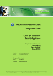
Cisco ASA 5500-X Series Hardware
Installation Guide
Cisco ASA 5512-X, ASA 5515-X, ASA 5525-X, ASA 5545-X, and ASA 5555-X
Cisco Systems, Inc.
www.cisco.com
Cisco has more than 200 offices worldwide.
Addresses, phone numbers, and fax numbers
are listed on the Cisco website at
www.cisco.com/go/offices.
THE SPECIFICATIONS AND INFORMATION REGARDING THE PRODUCTS IN THIS MANUAL ARE SUBJECT TO CHANGE WITHOUT NOTICE. ALL
STATEMENTS, INFORMATION, AND RECOMMENDATIONS IN THIS MANUAL ARE BELIEVED TO BE ACCURATE BUT ARE PRESENTED WITHOUT
WARRANTY OF ANY KIND, EXPRESS OR IMPLIED. USERS MUST TAKE FULL RESPONSIBILITY FOR THEIR APPLICATION OF ANY PRODUCTS.
THE SOFTWARE LICENSE AND LIMITED WARRANTY FOR THE ACCOMPANYING PRODUCT ARE SET FORTH IN THE INFORMATION PACKET THAT
SHIPPED WITH THE PRODUCT AND ARE INCORPORATED HEREIN BY THIS REFERENCE. IF YOU ARE UNABLE TO LOCATE THE SOFTWARE LICENSE
OR LIMITED WARRANTY, CONTACT YOUR CISCO REPRESENTATIVE FOR A COPY.
The following information is for FCC compliance of Class A devices: This equipment has been tested and found to comply with the limits for a Class A digital device, pursuant
to part 15 of the FCC rules. These limits are designed to provide reasonable protection against harmful interference when the equipment is operated in a commercial
environment. This equipment generates, uses, and can radiate radio-frequency energy and, if not installed and used in accordance with the instruction manual, may cause
harmful interference to radio communications. Operation of this equipment in a residential area is likely to cause harmful interference, in which case users will be required
to correct the interference at their own expense.
The following information is for FCC compliance of Class B devices: This equipment has been tested and found to comply with the limits for a Class B digital device, pursuant
to part 15 of the FCC rules. These limits are designed to provide reasonable protection against harmful interference in a residential installation. This equipment generates,
uses and can radiate radio frequency energy and, if not installed and used in accordance with the instructions, may cause harmful interference to radio communications.
However, there is no guarantee that interference will not occur in a particular installation. If the equipment causes interference to radio or television reception, which can be
determined by turning the equipment off and on, users are encouraged to try to correct the interference by using one or more of the following measures:
•
•
•
•
Reorient or relocate the receiving antenna.
Increase the separation between the equipment and receiver.
Connect the equipment into an outlet on a circuit different from that to which the receiver is connected.
Consult the dealer or an experienced radio/TV technician for help.
Modifications to this product not authorized by Cisco could void the FCC approval and negate your authority to operate the product.
The Cisco implementation of TCP header compression is an adaptation of a program developed by the University of California, Berkeley (UCB) as part of UCB’s public
domain version of the UNIX operating system. All rights reserved. Copyright © 1981, Regents of the University of California.
NOTWITHSTANDING ANY OTHER WARRANTY HEREIN, ALL DOCUMENT FILES AND SOFTWARE OF THESE SUPPLIERS ARE PROVIDED “AS IS” WITH
ALL FAULTS. CISCO AND THE ABOVE-NAMED SUPPLIERS DISCLAIM ALL WARRANTIES, EXPRESSED OR IMPLIED, INCLUDING, WITHOUT
LIMITATION, THOSE OF MERCHANTABILITY, FITNESS FOR A PARTICULAR PURPOSE AND NONINFRINGEMENT OR ARISING FROM A COURSE OF
DEALING, USAGE, OR TRADE PRACTICE.
IN NO EVENT SHALL CISCO OR ITS SUPPLIERS BE LIABLE FOR ANY INDIRECT, SPECIAL, CONSEQUENTIAL, OR INCIDENTAL DAMAGES, INCLUDING,
WITHOUT LIMITATION, LOST PROFITS OR LOSS OR DAMAGE TO DATA ARISING OUT OF THE USE OR INABILITY TO USE THIS MANUAL, EVEN IF CISCO
OR ITS SUPPLIERS HAVE BEEN ADVISED OF THE POSSIBILITY OF SUCH DAMAGES.
Cisco and the Cisco logo are trademarks or registered trademarks of Cisco and/or its affiliates in the U.S. and other countries. To view a list of Cisco trademarks, go to this
URL: www.cisco.com/go/trademarks. Third-party trademarks mentioned are the property of their respective owners. The use of the word partner does not imply a partnership
relationship between Cisco and any other company. (1110R)
Any Internet Protocol (IP) addresses and phone numbers used in this document are not intended to be actual addresses and phone numbers. Any examples, command display
output, network topology diagrams, and other figures included in the document are shown for illustrative purposes only. Any use of actual IP addresses or phone numbers in
illustrative content is unintentional and coincidental.
Cisco ASA 5500-X Series Hardware Installation Guide
© 2012-2013 Cisco Systems, Inc. All rights reserved.
CONTENTS
About This Guide
Contents
vii
vii
Document Objectives
vii
Document Conventions
Installation Warnings
vii
viii
Where to Find Safety and Warning Information
Related Documentation
xii
xii
Obtaining Documentation and Submitting a Service Request
CHAPTER
1
Information about the ASA 5500-X
xii
1-1
Cisco ASA 5500-X Series Chassis Overview
1-2
Internal and External USB Flash Drives 1-2
Internal USB Drive 1-2
(Optional) External USB Drives 1-2
Online Insertion and Removal Support 1-3
FAT 32 File System 1-3
Viewing Flash Memory 1-3
Solid State Drives
1-3
Management 0/0 Interface
Alarm LED
1-4
1-4
ASA 5500-X I/O Cards
SFP Modules
1-5
1-5
ASA Chassis Panels 1-6
Front Panel LEDs 1-6
Rear Panel LEDs 1-9
Rear Panel Ports 1-11
Power Supply
1-13
Hardware Specifications
1-15
Console Cable Pinouts 1-16
RJ-45 Console Cable 1-16
RJ-45 to DB-9 Console Adapter
1-18
Cisco ASA 5500-X Series Hardware Installation Guide
iii
Contents
CHAPTER
2
Preparing for Installation
Installation Overview
2-1
2-1
Safety Recommendations 2-1
Maintaining Safety with Electricity 2-2
Preventing Electrostatic Discharge Damage
Working in an ESD Environment 2-3
General Site Requirements 2-3
Site Environment 2-4
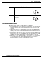
Preventive Site Configuration
Power Supply Considerations
Configuring Equipment Racks
CHAPTER
3
2-3
2-4
2-4
2-6
Installing and Connecting the ASA 5500-X
3-1
Rack Mounting the Chassis 3-1
Rack Mounting Guidelines 3-1
Rack Mounting the ASA 5512-X, 5515-X, and 5525-X With Brackets 3-2
Rack Mounting the ASA 5500-X Chassis with Slide Rail Mounting System 3-4
Preparing the ASA 5512-X, ASA 5515-X, or ASA 5525-X to Use an Optional Slide Rail Rack Mount
System 3-4
Rack Mounting the Chassis with the Slide Rail Mounting System 3-5
Connecting Cables, Turning on Power, and Verifying Connectivity
CHAPTER
4
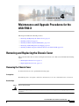
Maintenance and Upgrade Procedures for the ASA 5500-X
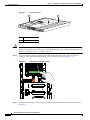
Removing and Replacing the Chassis Cover
Removing the Chassis Cover 4-1
Replacing the Chassis Cover 4-2
3-13
4-1
4-1
Installing an I/O Card 4-3
Installing an I/O Card in the Cisco ASA 5512-X, 5515-X, and 5525-X Chassis
Installing an I/O Card in the Cisco ASA 5545-X and 5555-X Chassis 4-7
Installing and Removing the SFP Modules
Installing the SFP Module 4-11
Removing the SFP Module 4-12
4-11
Removing and Installing the Power Supply 4-13
Removing and Installing the AC Power Supply
Installing the DC Input Power 4-15
Removing and Installing the DC Power Supply
4-13
4-19
Installing and Removing the Solid State Drive for the ASA CX SSP
Installation Scenarios 4-21
Cisco ASA 5500-X Series Hardware Installation Guide
iv
4-21
4-3
Contents
Installing and Removing SSDs
4-22
INDEX
Cisco ASA 5500-X Series Hardware Installation Guide
v
Contents
Cisco ASA 5500-X Series Hardware Installation Guide
vi
About This Guide
Revised: September 17, 2013
Contents
This preface includes the following sections:
•
Document Objectives, page vii
•
Document Conventions, page vii
•
Installation Warnings, page viii
•
Where to Find Safety and Warning Information, page xii
•
Related Documentation, page xii
•
Obtaining Documentation and Submitting a Service Request, page xii
Document Objectives
This guide describes how to install and maintain the Cisco ASA 5500-X series appliances. Information
in this guide applies to the following Cisco ASA 5500-X Series models: ASA 5512-X, ASA 5515-X,
ASA 5525-X, ASA 5545-X, and ASA 5555-X. References to “Cisco ASA 5500-X Series” and “ASA”
apply to all previously listed models unless specifically noted otherwise.
Document Conventions
This document uses the following conventions:
Convention
Indication
bold font
Commands and keywords and user-entered text appear in bold font.
italic font
Document titles, new or emphasized terms, and arguments for which you supply
values are in italic font.
[ ]
Elements in square brackets are optional.
Cisco ASA 5500-X Series Hardware Installation Guide
vii
{x | y | z }
Required alternative keywords are grouped in braces and separated by
vertical bars.
[x|y|z]
Optional alternative keywords are grouped in brackets and separated by
vertical bars.
string
A nonquoted set of characters. Do not use quotation marks around the string or
the string will include the quotation marks.
courier
font
courier bold
Terminal sessions and information the system displays appear in courier font.
font
courier italic
Commands and keywords and user-entered text appear in bold courier font.
font Arguments for which you supply values are in courier italic font.
< >
Nonprinting characters such as passwords are in angle brackets.
[ ]
Default responses to system prompts are in square brackets.
!, #
An exclamation point (!) or a pound sign (#) at the beginning of a line of code
indicates a comment line.
Note
Means reader take note.
Tip
Means the following information will help you solve a problem.
Caution
Means reader be careful. In this situation, you might perform an action that could result in equipment
damage or loss of data.
Installation Warnings
Be sure to read the Regulatory Compliance and Safety Information document at before installing the chassis.
This document contains important safety information. This section includes the following warnings:
•
Power Supply Disconnection Warning, page ix
•
Jewelry Removal Warning, page ix
•
Wrist Strap Warning, page ix
•
More than One Power Supply Warning, page ix
•
Work During Lightning Activity Warning, page ix
•
Installation Instructions Warning, page x
•
Chassis Warning for Rack-Mounting and Servicing, page x
•
SELV Circuit Warning, page x
•
Ground Conductor Warning, page x
•
Blank Faceplates and Cover Panels Warning, page x
•
Product Disposal Warning, page x
•
Short-Circuit Protection Warning, page xi
Cisco ASA 5500-X Series Hardware Installation Guide
viii
•
Compliance with Local and National Electrical Codes Warning, page xi
•
DC Power Connection Warning, page xi
•
AC Power Disconnection Warning, page xi
•
TN Power Warning, page xi
•
48 VDC Power System, page xi
•
Multiple Power Cord, page xi
•
Circuit Breaker (15A) Warning, page xi
•
Grounded Equipment Warning, page xii
•
Safety Cover Requirement, page xii
•
Faceplates and Cover Panel Requirement, page xii
Power Supply Disconnection Warning
Warning
Before working on a chassis or working near power supplies, unplug the power cord on AC units;
disconnect the power at the circuit breaker on DC units. Statement 12
Jewelry Removal Warning
Warning
Before working on equipment that is connected to power lines, remove jewelry (including rings,
necklaces, and watches). Metal objects will heat up when connected to power and ground and can
cause serious burns or weld the metal object to the terminals. Statement 43
Wrist Strap Warning
Warning
During this procedure, wear grounding wrist straps to avoid ESD damage to the card. Do not directly
touch the backplane with your hand or any metal tool, or you could shock yourself. Statement 94
More than One Power Supply Warning
Warning
This unit has more than one power supply connection; all connections must be removed completely
to completely remove power from the unit. Statement 102
Work During Lightning Activity Warning
Warning
Do not work on the system or connect or disconnect cables during periods of lightning activity.
Statement 1001
Cisco ASA 5500-X Series Hardware Installation Guide
ix
Installation Instructions Warning
Warning
Read the installation instructions before connecting the system to the power source. Statement 1004
Chassis Warning for Rack-Mounting and Servicing
Warning
To prevent bodily injury when mounting or servicing this unit in a rack, you must take special
precautions to ensure that the system remains stable. The following guidelines are provided to ensure
your safety: This unit should be mounted at the bottom of the rack if it is the only unit in the rack.When mounting
this unit in a partially filled rack, load the rack from the bottom to the top with the heaviest component at the bottom
of the rack.If the rack is provided with stabilizing devices, install the stabilizers before mounting or servicing the unit
in the rack. Statement 1006
SELV Circuit Warning
Warning
To avoid electric shock, do not connect safety extra-low voltage (SELV) circuits to telephone-network
voltage (TNV) circuits. LAN ports contain SELV circuits, and WAN ports contain TNV circuits. Some
LAN and WAN ports both use RJ-45 connectors. Use caution when connecting cables. Statement 1021
Ground Conductor Warning
Warning
This equipment must be grounded. Never defeat the ground conductor or operate the equipment in the
absence of a suitably installed ground conductor. Contact the appropriate electrical inspection
authority or an electrician if you are uncertain that suitable grounding is available. Statement 1024
Blank Faceplates and Cover Panels Warning
Warning
Blank faceplates and cover panels serve three important functions: they prevent exposure to
hazardous voltages and currents inside the chassis; they contain electromagnetic interference (EMI)
that might disrupt other equipment; and they direct the flow of cooling air through the chassis. Do not
operate the system unless all cards, faceplates, front covers, and rear covers are in place. Statement
1029
Product Disposal Warning
Warning
Ultimate disposal of this product should be handled according to all national laws and regulations.
Statement 1040
Cisco ASA 5500-X Series Hardware Installation Guide
x
Short-Circuit Protection Warning
Warning
This product requires short-circuit (overcurrent) protection, to be provided as part of the building
installation. Install only in accordance with national and local wiring regulations. Statement 1045
Compliance with Local and National Electrical Codes Warning
Warning
Installation of the equipment must comply with local and national electrical codes. Statement 1074
DC Power Connection Warning
Warning
After wiring the DC power supply, remove the tape from the circuit breaker switch handle and
reinstate power by moving the handle of the circuit breaker to the ON position. Statement 8
AC Power Disconnection Warning
Warning
Before working on a chassis or working near power supplies, unplug the power cord on AC units.
Statement 246
TN Power Warning
Warning
The device is designed to work with TN power systems. Statement 19
48 VDC Power System
Warning
The customer 48 volt power system must provide reinforced insulation between the primary AC power
and the 48 VDC output. Statement 128
Multiple Power Cord
Warning
This unit has more than one power cord. To reduce the risk of electric shock when servicing a unit,
disconnect the power cord of the power strip that the unit is plugged into. Statement 137
Circuit Breaker (15A) Warning
Warning
This product relies on the building’s installation for short-circuit (overcurrent) protection. Ensure that
a fuse or circuit breaker no larger than 120 VAC, 15A U.S. (240 VAC, 10A international) is used on the
phase conductors (all current-carrying conductors). Statement 13
Cisco ASA 5500-X Series Hardware Installation Guide
xi
Grounded Equipment Warning
Warning
This equipment is intended to be grounded. Ensure that the host is connected to earth ground during
normal use. Statement 39
Safety Cover Requirement
Warning
The safety cover is an integral part of the product. Do not operate the unit without the safety cover
installed. Operating the unit without the cover in place will invalidate the safety approvals and pose
a risk of fire and electrical hazards. Statement 117
Faceplates and Cover Panel Requirement
Warning
Blank faceplates and cover panels serve three important functions: they prevent exposure to
hazardous voltages and currents inside the chassis; they contain electromagnetic interference (EMI)
that might disrupt other equipment; and they direct the flow of cooling air through the chassis. Do not
operate the system unless all cards, faceplates, front covers, and rear covers are in place. Statement
142
Where to Find Safety and Warning Information
For safety and warning information, see the Regulatory Compliance and Safety Information document
at the following URL:
http://www.cisco.com/en/US/docs/security/asa/roadmap/asaroadmap.html#wp57708
This RCSI document describes the international agency compliance and safety information for the
Cisco ASA 5500-X series. It also includes translations of the safety warnings used in this guide.
Related Documentation
For a complete list of the Cisco ASA 5500-X series documentation and where to find it, see the
documentation roadmap at the following URL:
http://www.cisco.com/en/US/docs/security/asa/roadmap/asaroadmap.html
Obtaining Documentation and Submitting a Service Request
For information on obtaining documentation, using the Cisco Bug Search Tool (BST), submitting a
service request, and gathering additional information, see What’s New in Cisco Product Documentation
at: http://www.cisco.com/en/US/docs/general/whatsnew/whatsnew.html.
Subscribe to What’s New in Cisco Product Documentation, which lists all new and revised Cisco technical
documentation, as an RSS feed and deliver content directly to your desktop using a reader application. The
RSS feeds are a free service.
Cisco ASA 5500-X Series Hardware Installation Guide
xii
Cisco ASA 5500-X Series Hardware Installation Guide
xiii
Cisco ASA 5500-X Series Hardware Installation Guide
xiv
CH A P T E R
1
Information about the ASA 5500-X
This chapter describes the Cisco ASA 5512-X, 5515-X, 5525-X, 5545-X, and 5555-X models. We
recommend that you read this entire guide before beginning any of the procedures contained herein.
Warning
Only trained and qualified personnel should install, replace, or service this equipment. Statement 49
Caution
Read the safety warnings in the Regulatory Compliance and Safety Information document for the Cisco
ASA 5500-X, and follow proper safety procedures when performing any tasks in this guide. See
http://www.cisco.com/go/asadocs for links to the RCSI and other ASA documents.
This chapter includes the following topics:
•
Cisco ASA 5500-X Series Chassis Overview, page 1-2
•
Internal and External USB Flash Drives, page 1-2
•
Solid State Drives, page 1-3
•
Management 0/0 Interface, page 1-4
•
Alarm LED, page 1-4
•
ASA 5500-X I/O Cards, page 1-5
•
SFP Modules, page 1-5
•
ASA Chassis Panels, page 1-6
•
Power Supply, page 1-13
•
Hardware Specifications, page 1-15
•
Console Cable Pinouts, page 1-16
Cisco ASA 5500-X Series Hardware Installation Guide
1-1
Chapter 1
Information about the ASA 5500-X
Cisco ASA 5500-X Series Chassis Overview
Cisco ASA 5500-X Series Chassis Overview
This guide supports the Cisco ASA 5500-X series models, which includes the ASA 5512-X,
ASA 5515-X, ASA 5525-X, ASA 5545-X, and ASA 5555-X.
The Cisco ASA 5500-X series is a family of next-generation mid-range ASAs that are built on the same
security platform as the rest of the ASA family. These next-generation ASAs provide more firewall
throughput (4X firewall throughput), better scaling, more Ethernet ports (up to 14 GE ports), optional
ASA CX SSP or ASA IPS SSP software modules, and redundant power supplies on the 5545-X and
5555-X models.
For More Information
•
For information about ASA 5500-X performance, see the “Hardware Specifications” section on
page 1-15.
•
For information about ASA IPS functionality, see Cisco Intrusion Prevention System
documentation:
http://www.cisco.com/en/US/products/hw/vpndevc/ps4077/products_documentation_roadmaps_lis
t.html
•
For information about ASA CX functionality, see:
http://www.cisco.com/en/US/docs/security/asacx/roadmap/asacxprsmroadmap.html
Internal and External USB Flash Drives
The Cisco ASA 5500-X series chassis have internal and (optional) external USB drives.
•
Internal USB Drive, page 1-2
•
(Optional) External USB Drives, page 1-2
•
Online Insertion and Removal Support, page 1-3
•
FAT 32 File System, page 1-3
Internal USB Drive
An embedded USB (eUSB) device is used as the internal flash (disk0). See the “Hardware
Specifications” section on page 1-15 for the size shipped with each model.
(Optional) External USB Drives
The ASA 5500-X series supports external USB flash drives for data storage. The ASA 5500-X series use
disk1 as the external USB flash drive identifier. When the ASA is powered on, an inserted USB flash
drive is mounted to disk1 and available for you to use. Additionally, the file system commands that are
available to disk0 are also available to disk1, including copy, format, delete, mkdir, pwd, cd, and so
on. When you remove the USB flash drive, the system unmounts disk1, and disk1 becomes an invalid
file system label that you can no longer access.
If you insert a USB drive with more than one partition, only the first partition is mounted.
Cisco ASA 5500-X Series Hardware Installation Guide
1-2
Chapter 1
Information about the ASA 5500-X
Solid State Drives
Online Insertion and Removal Support
While the ASA back panel has two USB slots, only one is supported for Online Insertion and Removal
(OIR), with priority given to the USB drive that was inserted first. For example, based on the time
sequence, the first inserted USB flash drive is mounted to disk1, regardless of the slot in which you insert
it. When you insert a second USB device, an error message displays on the console to notify you that an
extra, unsupported USB flash drive exists. Removing either one of the USB devices does not change the
priority that you just established. To change the priority you must safely remove the USB device and
begin again to establish the desired priority.
FAT 32 File System
The ASA 5500-X series supports only FAT32 formatted file systems for the eUSB and external USB
drives. If you insert an external USB drive that is not in FAT 32 format, the system mounting process
fails, and you receive an error message. You can enter the format disk1: command to format the partition
to FAT 32 and mount the partition to disk1 again; however, data might be lost.
Viewing Flash Memory
Check the amount of free flash memory on the ASA by doing the following:
•
ASDM—Choose Tools > File Management. The amount of available memory appears on the
bottom left in the pane.
•
CLI—In privileged EXEC mode, enter the dir command. The amount of available memory appears
at the bottom of the output.
Solid State Drives
You must install a Cisco Solid State Drive (SSDs) for use with the ASA CX SSP. Only Cisco SSDs are
supported. Currently, the ASA CX SSP is the only process that can use the SSD for storage. You can
install one SSD in the ASA 5512-X, ASA 5515-X, and ASA 5525-X. You can install two SSDs in a
RAID 1 configuration in the ASA 5545-X and ASA 5555-X.
Note
When you install an SSD for the first time, you must reload the ASA and then reimage the ASA CX SSP.
The SSD is hot-swappable. The SSD resides in a carrier, which you install into the drive bay. You can
use the SSD with an AC or DC power supply.
Cisco ASA 5500-X Series Hardware Installation Guide
1-3
Chapter 1
Information about the ASA 5500-X
Management 0/0 Interface
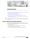
Figure 1-1 shows the SSD in the carrier that it is shipped in.
SSD in Carrier
334564
Figure 1-1
Management 0/0 Interface
You manage the ASA through the Management 0/0 interface. The Management 0/0 interface has the
following characteristics:
•
No through traffic support
•
No subinterface support
•
No priority queue support
•
No multicast MAC support
•
The IPS or CX SSP software module and the ASA share the Management 0/0 interface; however,
each has its own separate MAC address and IP address. You must configure the module IP address
within the module operating system. However, you configure physical characteristics (such as
enabling the interface) on the ASA.
The Management 0/0 interface is configured for management-only traffic, and you cannot disable
management-only for the Management interface. Also, because the ASA 5500-X models do not allow
subinterfaces on the Management interface, for per-context management, you must connect to a data
interface for management.
The Management 0/0 interface is configured for ASDM access as part of the default factory
configuration.
For More Information
For more information, see the “Rear Panel Ports” section on page 1-11.
Alarm LED
The ASA 5500-X series chassis perform autonomous environment monitoring to poll all external sensors
and monitor operating conditions. In the event of damage to certain internal components or surpassed
temperature thresholds, the system activates an alarm LED to notify you of a critical condition. For
example, the alarm LED is activated by firmware in the event of various critical over-voltage and
over-temperature conditions, as well as when the ASA has missing or unrecognized internal chip
components. When the alarm LED lights, you can find details about the system condition from the
system message that appears on the console or by entering the show environment or show controller
pci command.
Cisco ASA 5500-X Series Hardware Installation Guide
1-4
Chapter 1
Information about the ASA 5500-X
ASA 5500-X I/O Cards
ASA 5500-X I/O Cards
The Cisco ASA 5500-X Series 6-port Gigabit Ethernet interface cards extend the I/O capabilities of the
ASA 5525-X, ASA 5545-X, and ASA 5555-X models by providing additional Gigabit Ethernet ports.
The I/O cards provide the following benefits:
•
Segmentation of network traffic into separate security zones
•
Fiber optic cable connectivity for communicating over long distances
•
Load sharing of traffic and protection against link failure by using EtherChannel
•
Support for Jumbo Ethernet frames of up to 9000 bytes
•
Protection for Active/Active failover and of full-mesh firewall deployments against cable failure
For More Information
For information about installing an I/O card in your ASA, see Chapter 4, “Maintenance and Upgrade
Procedures for the ASA 5500-X.”
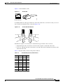
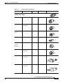
SFP Modules
The ASA uses a field-replaceable SFP module to establish Gigabit Ethernet connections. Table 1-1 lists
the supported SFP modules.
Table 1-1
Supported SFP Modules
SFP Module
Type of Connection
Cisco Part Number
1000BASE-LX/LH
Fiber-optic
GLC-LH-SM=
1000BASE-SX
Fiber-optic
GLC-SX-MM=
The 1000BASE-LX/LH and 1000BASE-SX SFP modules are used to establish fiber-optic connections.
Use fiber-optic cables with LC connectors to connect to an SFP module. The SFP modules support 850
to 1550 nm nominal wavelengths. The cables must not exceed the required cable length for reliable
communications. Table 1-2 lists the cable length requirements.
Table 1-2
Cabling Requirements for Fiber-Optic SFP Modules
SFP
Module
62.5/125 micron
Multimode 850
nm Fiber
50/125 micron
Multimode 850
nm Fiber
62.5/125 micron
Multimode 1310
nm Fiber
50/125 micron
9/125 micron
Multimode 1310 Single-mode
nm Fiber
1310 nm Fiber
LX/LH
—
—
550 m at
500 Mhz-km
550 m at
400 Mhz-km
10 km
SX
275 m at
200 Mhz-km
550 m at
500 Mhz-km
—
—
—
Use only Cisco certified SFP modules on the ASA. Each SFP module has an internal serial EEPROM
that is encoded with security information. This encoding provides a way for Cisco to identify and
validate that the SFP module meets the requirements for the ASA.
Cisco ASA 5500-X Series Hardware Installation Guide
1-5
Chapter 1
Information about the ASA 5500-X
ASA Chassis Panels
Note
Only SFP modules certified by Cisco are supported on the ASA.
ASA Chassis Panels
This section describes the front and rear ASA panels, and it includes the following topics:
•
Front Panel LEDs, page 1-6
•
Rear Panel LEDs, page 1-9
•
Rear Panel Ports, page 1-11
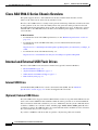
Front Panel LEDs
This section describes the front panel LEDs for the Cisco ASA 5500-X series chassis.
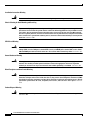
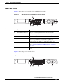
Figure 1-2 shows the front panel LEDs for the ASA 5512-X, ASA 5515-X, and ASA 5525-X models.
Figure 1-2
Front Panel LEDs for the Cisco ASA 5512-X, ASA 5515-X, and ASA 5525-X
1
Cisco ASA 5515
Adapative Security Appliance
8
7
6
BOOT
ALARM
ACTIVE
VPN
PS
HD
5
4
3
2
Cisco ASA 5515
Adapative Security Appliance
ALARM
ACTIVE
VPN
PS
HD
282360
BOOT
1
LED
Description
Power button
A soft switch that turns the system on and off. Once depressed, the
button stays in the “on” position:
•
On—The power symbol on the button illuminates.
•
Off—The power symbol on the button is dark.
For information about the power state, see the “Power Supply
Considerations” section on page 2-4.
2
Hard disk release button
Cisco ASA 5500-X Series Hardware Installation Guide
1-6
Releases the hard disk from the device.
Chapter 1
Information about the ASA 5500-X
ASA Chassis Panels
3
Alarm
Indicates system operating status:
•
Off—Normal operating system function.
•
Flashing amber—Critical Alarm indicating one or more of the
following:
– a major failure of a hardware or software component.
– an over-temperature condition.
– power voltage is outside of the tolerance range.
4
5
VPN
HD
Indicates VPN tunnel status:
•
Solid green—VPN tunnel is established.
•
Off—No VPN tunnel is established.
Indicates Hard Disk Drive status:
•
Flashing green—Proportioned to read/write activity.
•
Solid amber—Hard disk drive failure.
•
Off—No hard disk drive present.
6
PS
Indicates the power supply status
7
Active
Indicates the status of the failover pair:
8
Boot
•
Solid green—Failover pair is operating normally.
•
Off—Failover is not operational.
Indicates power-up diagnostics:
•
Flashing green—Power-up diagnostics are running, or system
is booting.
•
Solid green—System has passed power-up diagnostics.
•
Off—Power-up diagnostics are not operational.
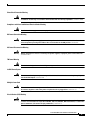
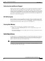
Figure 1-3 shows the front panel LEDs for the ASA 5545-X and ASA 5555-X models.
Cisco ASA 5500-X Series Hardware Installation Guide
1-7
Chapter 1
Information about the ASA 5500-X
ASA Chassis Panels
Figure 1-3
Front Panel LEDs for Cisco ASA 5545-X and ASA 5555-X
2
1
3
Cisco ASA 5545
Adapative Security Appliance
BOOT
ACTIVE
PS1
PS0
13
12
11
10
1
ALARM
VPN
HD1
HD0
0
9
8
6
5
4
7
Cisco ASA 5545
Adapative Security Appliance
ALARM
VPN
HD1
HD0
1
0
282359
BOOT
ACTIVE
PS1
PS0
1
LED
Description
Power button
A soft switch that turns the system on and off. Once depressed, the
button stays in the “on” position:
•
On—The power symbol on the button illuminates.
•
Off—The power symbol on the button is dark.
For information about the power state, see the “Power Supply
Considerations” section on page 2-4.
2
Hard disk slot
Indicates the slot for hard disk 1.
3
Hard disk release button
Releases hard disk 1 from the device.
4
Hard disk release button
Releases hard disk 0 from the device.
5
Hard disk slot
Indicates the slot for hard disk 0.
6
Alarm
Indicates system operating status:
•
Off—Normal operating system function
•
Flashing amber—Critical Alarm indicating one or more of the
following:
– a major failure of a hardware or software component.
– an over-temperature condition.
– power voltage is outside of the tolerance range.
7
VPN
Cisco ASA 5500-X Series Hardware Installation Guide
1-8
Indicates VPN tunnel status:
•
Solid green—VPN tunnel is established.
•
Off—No VPN tunnel is established.
Chapter 1
Information about the ASA 5500-X
ASA Chassis Panels
8
9
HD1
Indicates Hard Disk Drive 1 status:
HD0
•
Flashing green—Proportioned to read/write activity.
•
Solid amber—Hard disk drive failure.
•
Off—No hard disk drive present.
Indicates Hard Disk Drive 0 status:
•
Flashing green—Proportioned to read/write activity.
•
Solid amber—Hard disk drive failure.
•
Off—No hard disk drive present.
10
PS1
Indicates the status of the optional redundant power supply.
11
PS0
Indicates the status of the primary power supply that ships with the
product.
12
Active
Indicates the status of the failover pair:
13
Boot
•
Solid green—Failover pair is operating normally.
•
Off—Failover pair is not operational.
Indicates power-up diagnostics:
•
Flashing green—Power-up diagnostics are running, or system
is booting.
•
Solid green—System has passed power-up diagnostics.
•
Off—Power-up diagnostics are not operational.
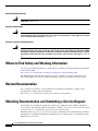
Rear Panel LEDs
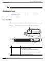
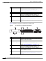
Figure 1-4 shows the rear panel LEDs for the ASA 5500-X series chassis.
Rear Panel LEDs for ASA 5500-X Series Chassis
1
3
2
5
4
7
6
332118
Figure 1-4
Cisco ASA 5500-X Series Hardware Installation Guide
1-9
Chapter 1
Information about the ASA 5500-X
ASA Chassis Panels
1
2
LED
Description
Power
Indicates power supply status:
Alarm
•
Off—Power supply off.
•
Solid green—Power supply on.
Indicates system operating status:
•
Off—Normal operating system function
•
Flashing amber—Critical Alarm indicating one or more of the
following:
– a major failure of a hardware or software component.
– an over-temperature condition.
– power voltage is outside of the tolerance range.
3
4
5
6
7
Boot
Active
VPN
HD0
HD1
Cisco ASA 5500-X Series Hardware Installation Guide
1-10
Indicates power-up diagnostics:
•
Flashing green—Power-up diagnostics are running, or system
is booting.
•
Solid green—System has passed power-up diagnostics.
•
Off—Power-up diagnostics are not operational.
Indicates the status of the failover pair:
•
Solid green—Failover pair is operating normally.
•
Off—Failover pair is not operational.
Indicates VPN tunnel status:
•
Solid green—VPN tunnel is established.
•
Off—No VPN tunnel is established.
Indicates Hard Disk Drive 0 status:
•
Flashing green—Proportioned to read/write activity.
•
Solid amber—Hard disk drive failure.
•
Off—No hard disk drive present.
Indicates Hard Disk Drive 1 status:
•
Flashing green—Proportioned to read/write activity.
•
Solid amber—Hard disk drive failure.
•
Off—No hard disk drive present.
Chapter 1
Information about the ASA 5500-X
ASA Chassis Panels
Rear Panel Ports
Figure 1-5 shows the ports for the ASA 5512-X and ASA 5515-X models.
Figure 1-5
Rear Panel Ports for the ASA 5512-X and ASA 5515-X
282361
1
5
3
4
2
.
1
LED
Description
Management 0/0 interface
Indicates the Gigabit Ethernet interface that is restricted to
management use only. Connect with an RJ-45 cable.
(See the “Management 0/0 Interface” section on page 1-4.)
2
Power supply
Indicates the chassis power supply.
3
RJ-45 ports
Indicates the Gigabit Ethernet customer data interfaces.
The top row port numbers are (from left to right) 5, 3, 1.
The bottom row port numbers are (from left to right) 4, 2, 0.
4
USB Ports
Indicates the two USB standard ports.
(See the “Internal and External USB Flash Drives” section on
page 1-2.)
5
Console port
Indicates the console port that directly connects a computer to the
ASA.
Figure 1-6 shows the ports for the ASA 5525-X.
Rear Panel Ports for the ASA 5525-X
1
332896
Figure 1-6
5
4
3
2
Cisco ASA 5500-X Series Hardware Installation Guide
1-11
Chapter 1
Information about the ASA 5500-X
ASA Chassis Panels
1
LED
Description
Management 0/0 interface
Indicates the Gigabit Ethernet interface that is restricted to
management use only. Connect with an RJ-45 cable.
(See the “Management 0/0 Interface” section on page 1-4.)
2
Power supply
Indicates the chassis power supply.
3
RJ-45 ports
Indicates the Gigabit Ethernet customer data interfaces.
The top row port numbers are (from left to right) 7, 5, 3, 1.
The bottom row port numbers are (from left to right) 6, 4, 2, 0.
4
USB Ports
Indicates the two USB standard ports.
(See the “Internal and External USB Flash Drives” section on
page 1-2.)
5
Console port
Indicates the console port that directly connects a computer to the
ASA.
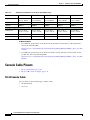
Figure 1-7 shows the rear panel ports for the ASA 5545-X and ASA 5555-X.
Rear Panel Ports for the ASA 5545-X and ASA 5555-X
2
3
7
6
4
5
PO
W
E
AL R
AR
M
BO v
O
AC T
TI
VE
VP
N
H
D
1
282362
Figure 1-7
8
LED
Description
1
I/O slot
Slot for the optional I/O Card. If you have a fiber I/O card, use SFP
modules to connect (not included).
2
Thumbscrew
The screw that tightens and loosens the chassis cover.
3
Management 0/0 port
Indicates the Gigabit Ethernet interface that is restricted to
management use only. Connect with an RJ-45 cable.
(See the “Management 0/0 Interface” section on page 1-4.)
4
RJ-45 ports
Indicates the Gigabit Ethernet customer data interfaces.
The top row port numbers are (from left to right) 7, 5, 3, 1.
The bottom row port numbers are (from left to right) 6, 4, 2, 0.
5
Power supplies
Slots for the primary power supply that ships with the device and the
optional redundant power supply.
6
USB ports
Indicates the two USB standard ports.
(See the “Internal and External USB Flash Drives” section on
page 1-2.)
Cisco ASA 5500-X Series Hardware Installation Guide
1-12
Chapter 1
Information about the ASA 5500-X
Power Supply
7
Console port
Indicates the console port that directly connects a computer to the
ASA.
8
Rear panel LEDs
Shows the rear panel LEDs. (See the “Rear Panel LEDs for ASA
5500-X Series Chassis” for more information.)
Power Supply
The ASA 5512-X, ASA 5515-X, and ASA 5525-X ship with one fixed fan and one fixed power supply
(AC or DC) installed. The ASA 5545-X and ASA 5555-X ship with one power supply (AC or DC)
installed. You can add an additional power supply or you can order these appliances with two power
supplies installed. Having two power supplies installed provides a redundant power option. This
configuration ensures that if one power supply fails, the other power supply assumes the full load until
the failed power supply is replaced. To maintain airflow, an empty bay must be covered or both bays
must be populated with power supplies. If only one power supply is installed, make sure that it is
installed in slot 0 (left slot) and that slot 1 (right slot) is covered with a slot cover. If only one power
supply is installed, do not remove the power supply unless the appliance has been powered off.
Removing the only operational power supply causes an immediate power loss.
Note
The ASA 5545-X and ASA 5555-X can support two AC or two DC power supplies. Do not mix AC and
DC power supply units in the same chassis.
The power supplies each provide 400 W of output power and are used in a 1 + 1 redundant configuration.
There is no input switch on the faceplate of the power supplies.
The Cisco ASA 5500-X series hardware operates on AC power and supports the ability to restore the
previous power state of the system in the event that AC power is lost.
The power supply is switched from Standby to ON by way of a system chassis STANDBY/ON switch.
Earlier ASAs (V01) require you to turn on the power with the power switch. Newer ASAs (V02)
automatically turn on when you plug in the power cable. To determine your version, do one of the
following:
•
At the CLI, enter the show inventory command and look for V01 or V02 in the output.
•
On the back of the chassis, look at the VID PID label for V01 or V02.
For the V01 chassis, see the following limitations:
•
The ASA requires 50 seconds from the time that AC power is applied before the power state can be
updated and stored. This means that any changes to the power state within the first 50 seconds of
applying AC power will not be observed if AC power is removed within that time.
•
The ASA requires 10 seconds from the time it is placed into standby mode before the power state
can be updated and stored. This means any changes to the power state within the first 10 seconds of
entering standby mode (including the standby mode itself) will not be observed if AC power is
removed within that time.
For the V02 chassis, the above limitations to not apply.
The power supply slot numbers are on the back of the chassis to the left side of each power supply. When
facing the back of the chassis, power supply slot 0 (PS0) is to the left and power supply slot 1(PS1) is to
the right. By default, the factory installs a single power supply in slot 0.
The ASA supports the following power supplies:
Cisco ASA 5500-X Series Hardware Installation Guide
1-13
Chapter 1
Information about the ASA 5500-X
Power Supply
•
AC power supply—Provides 400 watt output power with two DC voltage outputs: +12 V and +5 V.
The AC power supply operates between 85 and 264 VAC. The AC power supply current shares on
the 12 V output and is used in a dual hot pluggable configuration. The AC power supply consumes
a maximum of 471 W of input power.
•
DC power supply—Provides 400 watt output power with two DC voltage outputs: +12 V and +5.0
V. The power supply operates between –40.5 and –72 VDC. The DC power supply current shares on
the 12 V output and is used in a dual hot pluggable configuration. The DC power supply consumes
a maximum of 500 W of input power.
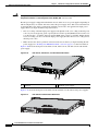
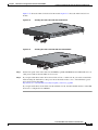
Figure 1-8 shows both the removable AC (on the left) and DC (on the right) power supplies for the
ASA 5545-X and ASA 5555-X.
AC Power Supply and DC Power Supply
333056
Figure 1-8
1
1
2
3
4
1
Power supply indicator
2
DC power supply positive connection
3
DC power supply neutral connection
4
DC power supply negative connection
Table 1-3 describes the power supply indicator. The function of the indicator is the same for both the AC
and DC power supplies.
Cisco ASA 5500-X Series Hardware Installation Guide
1-14
Chapter 1
Information about the ASA 5500-X
Hardware Specifications
Table 1-3
AC and DC Power Supply Indicator
Indicator Color and State
Description
Solid green
Power output is on and within the normal operating range.
Blinking green, at the rate of one
blink per second
Input power that is within the normal operating range is being
supplied, but the Standby switch is in the Standby position (and
not in the On position).
Solid amber
A power supply critical event has occurred, and the power
supply has shut down. The critical event can be temperature,
voltage, current, or fan operating outside the normal operating
range.
Blinking amber, at the rate of one
blink per second
A power supply warning event has occurred, but the power
supply can continue to operate. The warning event can be
temperature, voltage, current, or fan operating outside the
normal operating range.
Off
The power supply is shut down.
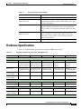
Hardware Specifications
Table 1-4 contains hardware specifications for the ASA 5500-X series models.
Table 1-4
Hardware Specifications for the Cisco ASA 5500-X series
ASA 5512-X
ASA 5515-X
ASA 5525-X
ASA 5545-X
ASA 5555-X
Physical Specifications
Form-factor
1RU, 19-in
1RU, 19-in
1RU, 19-in
1RU, 19-in
1RU, 19-in
Rack mountable
Yes.
Brackets included,
slide rails optional
Yes.
Brackets included,
slide rails optional
Yes.
Brackets included,
slide rails optional
Yes.
Slide rails
included.
Yes.
Slide rails
included.
Dimensions
1.67x1.67x1.56 in. 1.67x1.67x1.56 in. 1.67x1.67x1.56 in. 1.67x1.67x1.91 in. 1.67x1.67x1.91 in.
42.4x429x395 mm 42.4x429x395 mm 42.4x429x395 mm 42.4x429x484 mm 42.4x429x484 mm
Weight—single
power supply
13.39 lb.
13.39 lb.
14.92 lb.
16.82 lb.
16.82 lb.
Weight—dual
power supply
N/A
N/A
N/A
18.86 lb.
18.86 lb.
Technical Specifications
DRAM Memory
4 GB
8 GB
8 GB
12 GB
16 GB
Internal Flash
4 GB
8 GB
8 GB
8 GB
8 GB
Power Supply Information
Power supply
400 W
400W
400W
450W
450W
Redundant power
supply available
No
No
No
Yes
Yes
Operating Conditions
Cisco ASA 5500-X Series Hardware Installation Guide
1-15
Chapter 1
Information about the ASA 5500-X
Console Cable Pinouts
Table 1-4
Hardware Specifications for the Cisco ASA 5500-X series
ASA 5512-X
ASA 5515-X
ASA 5525-X
ASA 5545-X
ASA 5555-X
Temperature
-5°C to 40°C
(23°F to 104°F)
-5°C to 40°C
(23°F to 104°F)
-5°C to 40°C
(23°F to 104°F)
-5°C to 40°C
(23°F to 104°F)
-5°C to 40°C
(23°F to 104°F)
Relative humidity
90%
90%
90%
90%
90%
Altitude
10,000 ft.
10,000 ft.
10,000 ft.
10,000 ft.
10,000 ft.
Non-Operating Conditions
Temperature
-25°C to 70°C
(-13°F to 158°F)
-25°C to 70°C
(-13°F to 158°F)
-25°C to 70°C
(-13°F to 158°F)
-25°C to 70°C
(-13°F to 158°F)
-25°C to 70°C
(-13°F to 158°F)
Relative humidity
10% to 90%
10% to 90%
10% to 90%
10% to 90%
10% to 90%
Altitude
15,000 ft.
15,000 ft.
15,000 ft.
15,000 ft.
15,000 ft.
For More Information
•
For additional specifications on the ASA 5512-X and ASA 5515-X models, see the product data
sheet at the following URL:
http://www.cisco.com/en/US/prod/collateral/vpndevc/ps6032/ps6094/ps6120/data_sheet_c78-7012
53.html
•
For additional specifications on the ASA 5525-X ASA 5545-X and ASA 5555-X models, see the
product data sheet at the following URL:
http://www.cisco.com/en/US/prod/collateral/vpndevc/ps6032/ps6094/ps6120/data_sheet_c78-7018
08.html
Console Cable Pinouts
•
RJ-45 Console Cable, page 1-16
•
RJ-45 to DB-9 Console Adapter, page 1-18
RJ-45 Console Cable
Cisco products use the following types of RJ-45 cables:
•
Straight-through
•
Crossover
Cisco ASA 5500-X Series Hardware Installation Guide
1-16
Information about the ASA 5500-X
Console Cable Pinouts
Figure 1-9 shows the RJ 45 cable.
RJ-45 Cable
H2936
Figure 1-9
87654321
RJ-45 connector
To identify the RJ-45 cable type, hold the two ends of the cable next to each other so that you can see
the colored wires inside the ends, as shown in Figure 1-10.
Figure 1-10
RJ-45 Cable Identification
H5663
Chapter 1
Examine the sequence of colored wires to determine the type of RJ-45 cable, as follows:
•
Straight-through—The colored wires are in the same sequence at both ends of the cable.
•
Crossover—The first (far left) colored wire at one end of the cable is the third colored wire at the
other end of the cable.
Table 1-5 lists the rolled (console) cable pinouts for RJ-45.
Table 1-5
RJ-45 Rolled (Console) Cable Pinouts
Signal Pin
Pin
Pin
-
1
8
-
-
2
7
-
-
3
6
-
-
4
5
-
-
5
4
-
-
6
3
-
-
7
2
-
-
8
1
-
Cisco ASA 5500-X Series Hardware Installation Guide
1-17
Chapter 1
Console Cable Pinouts
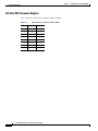
RJ-45 to DB-9 Console Adapter
Table 1-6 lists the cable pinouts for RJ-45 to DB-9 or DB-25.
Table 1-6
Cable Pinouts for RJ-45 to DB-9 or DB-25
Signal
RJ-45 Pin
DB-9 Pin
RTS
1
7
DTR
2
4
TxD
3
3
GND
4
5
GND
5
5
RxD
6
2
DSR
7
6
CTS
8
8
Cisco ASA 5500-X Series Hardware Installation Guide
1-18
Information about the ASA 5500-X
CH A P T E R
2
Preparing for Installation
The information in this guide applies to the following Cisco ASA 5500-X series models: ASA 5512-X,
5515-X, 5525-X, 5545-X, and 5555-X.
In this guide, references to “Cisco ASA 5500-X series ” and “ASA” apply to all models unless specifically
noted otherwise.
This chapter describes the steps to follow before installing new hardware or performing hardware
upgrades, and it includes the following sections:
•
Installation Overview, page 2-1
•
Safety Recommendations, page 2-1
•
General Site Requirements, page 2-3
Installation Overview
To prepare for the installation of the chassis, perform the following steps:
Step 1
Review the safety precautions outlined in the Regulatory Compliance and Safety Information document
for the ASA 500-X. See http://www.cisco.com/go/asadocs for links to the RCSI and other ASA
documents.
Step 2
Read the ASA release notes for your software version.
Step 3
Unpack the chassis and accessories.
Step 4
Place the chassis on a stable work surface.
Step 5
Follow the directions for mounting the chassis in a rack in the “Rack Mounting the Chassis” section on
page 3-1.
Step 6
Follow the directions for establishing network connectivity in the “Connecting Cables, Turning on
Power, and Verifying Connectivity” section on page 3-13.
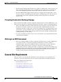
Safety Recommendations
Use the following guidelines and the information in the following sections to help ensure your safety and
protect the ASA. The list of guidelines may not address all potentially hazardous situations in your
working environment, so be alert and exercise good judgement at all times.
Cisco ASA 5500-X Series Hardware Installation Guide
2-1
Chapter 2
Preparing for Installation
Safety Recommendations
Note
If you need to remove the chassis cover to install a hardware component, such as additional memory or
an interface card, doing so does not affect your Cisco warranty. Upgrading the ASA does not require any
special tools and does not create any radio frequency leaks.
Observe the following safety guidelines:
•
Keep the chassis area clear and dust-free before, during, and after installation.
•
Keep tools away from walk areas in which you and others might fall over them.
•
Do not wear loose clothing or jewelry, such as earrings, bracelets, or chains that could get caught in
the chassis.
•
Wear safety glasses if you are working under any conditions that might be hazardous to your eyes.
•
Do not perform any action that creates a potential hazard to people or makes the equipment unsafe.
•
Never attempt to lift an object that is too heavy for one person to handle.
This section includes the following topics:
•
Maintaining Safety with Electricity, page 2-2
•
Preventing Electrostatic Discharge Damage, page 2-3
•
Working in an ESD Environment, page 2-3
Maintaining Safety with Electricity
Warning
Before working on a chassis or working near power supplies, unplug the power cord on AC units;
disconnect the power at the circuit breaker on DC units. Statement 12
Follow these guidelines when working on equipment powered by electricity:
•
Before beginning procedures that require access to the interior of the chassis, locate the emergency
power-off switch for the room in which you are working. Then, if an electrical accident occurs, you
can act quickly to turn off the power.
•
Do not work alone if potentially hazardous conditions exist anywhere in your work space.
•
Never assume that power is disconnected from a circuit; always check the circuit.
•
Look carefully for possible hazards in your work area, such as moist floors, ungrounded power
extension cables, frayed power cords, and missing safety grounds.
•
If an electrical accident occurs, proceed as follows:
– Use caution; do not become a victim yourself.
– Disconnect power from the system.
– If possible, send another person to get medical aid. Otherwise, assess the condition of the
victim, and then call for help.
– Determine whether or not the person needs rescue breathing or external cardiac compressions;
then take appropriate action.
•
Use the ASA chassis within its marked electrical ratings and product usage instructions.
•
Install the ASA in compliance with local and national electrical codes as listed in the REgulatory
Compliance and Safety Information document.
Cisco ASA 5500-X Series Hardware Installation Guide
2-2
Chapter 2
Preparing for Installation
General Site Requirements
•
The ASA models equipped with AC-input power supplies are shipped with a 3-wire electrical cord
with a grounding-type plug that fits only a grounding-type power outlet. Do not circumvent this
safety feature. Equipment grounding should comply with local and national electrical codes.
•
The ASA 5500-X models equipped with AC-input power supplies and are shipped with a 3-wire
electrical cord with a grounding-type plug that fits into a grounding-type power outlet only. Do not
circumvent this safety feature. Equipment grounding should comply with local and national
electrical codes.
Preventing Electrostatic Discharge Damage
Electrostatic discharge (ESD) can damage equipment and impair electrical circuitry. ESD damage occurs
when electronic components are improperly handled and can result in complete or intermittent failures.
•
Always follow ESD-prevention procedures when removing and replacing components. Ensure that
the chassis is electrically connected to an earth ground. Wear an ESD-preventive wrist strap,
ensuring that it makes good skin contact. Connect the grounding clip to an unpainted surface of the
chassis frame to safely ground ESD voltages. To properly guard against ESD damage and shocks,
the wrist strap and cord must operate effectively. If no wrist strap is available, ground yourself by
touching the metal part of the chassis.
•
For safety, periodically check the resistance value of the antistatic strap, which should be between
1 and 10 megohms (Mohms).
Working in an ESD Environment
•
Electrostatic discharge (ESD) can damage equipment and impair electrical circuitry. ESD damage
occurs when electronic components are improperly handled and can result in complete or
intermittent failures. Always follow ESD-prevention procedures when you remove and replace
components. Ensure that the chassis is electrically connected to earth ground. Wear an
ESD-preventive wrist strap, ensuring that it makes good skin contact. Connect the grounding clip to
an unpainted surface of the chassis frame to safely ground unwanted ESD voltages. To guard against
ESD damage and shocks, the wrist strap and cord must operate properly. If no wrist strap is
available, ground yourself by touching the metal part of the chassis.
General Site Requirements
The topics in this section describe the requirements your site must meet for safe installation and
operation of your system. Ensure that your site is properly prepared before beginning installation.
This section includes the following topics:
•
Site Environment, page 2-4
•
Preventive Site Configuration, page 2-4
•
Power Supply Considerations, page 2-4
•
Configuring Equipment Racks, page 2-6
Cisco ASA 5500-X Series Hardware Installation Guide
2-3
Chapter 2
Preparing for Installation
General Site Requirements
Site Environment
Place the chassis on a desktop or mount it on a rack. The location of the chassis and the layout of the
equipment rack or wiring room are extremely important for proper system operation. Placing equipment
too close together with inadequate ventilation and inaccessible panels can cause system malfunctions
and shutdowns. Improper placement can also make it difficult for you to access the chassis for
maintenance.
For information about physical specifications, see the “Hardware Specifications” section on page 1-15.
When planning the site layout and equipment locations, keep in mind the precautions described in the
next section “Preventive Site Configuration, page 2-4,” to help avoid equipment failures and reduce the
possibility of environmentally caused shutdowns. If you are currently experiencing shutdowns or
unusually high error rates with your existing equipment, these precautions may help you isolate the
cause of failures and prevent future problems.
Preventive Site Configuration
The following precautions will help plan an acceptable operating environment for the chassis and avoid
environmentally caused equipment failures:
•
Electrical equipment generates heat. Ambient air temperature might not be adequate to cool
equipment to acceptable operating temperatures without adequate circulation. Ensure that the room
in which you operate your system has adequate air circulation.
•
Always follow the ESD-prevention procedures described previously to avoid damage to equipment.
Damage from static discharge can cause immediate or intermittent equipment failure.
•
Ensure that the chassis cover is secure. The chassis is designed to allow cooling air to flow
effectively within it. An open chassis allows air leaks, which may interrupt and redirect the flow of
cooling air from the internal components.
Power Supply Considerations
Observe the following considerations:
•
Check the power at the site before installing the chassis to ensure that the power is “clean” (free of
spikes and noise). Install a power conditioner, if necessary, to ensure proper voltages and power
levels in the source voltage.
•
Install proper grounding for the site to avoid damage from lightning and power surges.
•
The ASA chassis does not have a user-selectable operating range. Refer to the label on the chassis
for the correct AC-input power requirement.
•
Several styles of AC-input power supply cords are available; make sure that you have the correct
style for your site.
•
Install an uninterruptible power source for your site, if possible.
You also need to provide power to the switch with the appropriate AC power cord for your location.
Table 2-1 lists the power cords that are used with the AC power supply.
Cisco ASA 5500-X Series Hardware Installation Guide
2-4
Preparing for Installation
General Site Requirements
Table 2-1
Locale
AC-Input Power Cord Options
Part Number
Length
Plug Rating
Plug Type
Appliance Coupler
120352
300 W AC Power Supply
8.2 ft (2.5 m) 125 VAC, 10 A
Australia,
8.2 ft (2.5 m) 250 VAC, 10 A
120354
North America CAB-AC (72-0259)
120356
CAB-ACA
(72-0746-01)
120357
Europe (except CAB-ACE (72-0460) 8.2 ft (2.5 m) 250 VAC, 10 A
Italy)
CAB-ACI 72-0556
8.2 ft (2.5 m) 250 VAC, 10 A
Singapore
CAB-ACU 72-0557
8.2 ft (2.5 m) 250 VAC, 10 A
Argentina
CAB-ACR
(37-0995-01)
8.2 ft (2.5 m) 250 VAC, 10 A
Switzerland
CAB-ACS
(72-1483-01)
8.2 ft (2.5 m) 250 VAC, 10 A
Japan
CAB-JPN
(72-1925-01)
8.2 ft (2.5 m) 250 VAC, 10 A
120358
Italy
120359
United
Kingdom
251248
251247
120356
Chapter 2
Cisco ASA 5500-X Series Hardware Installation Guide
2-5
Chapter 2
Preparing for Installation
General Site Requirements
Table 2-1
AC-Input Power Cord Options (continued)
Locale
Part Number
Length
Plug Rating
India
CAB-IND-10A
8.2 ft (2.5 m) 250 VAC, 10 A
Plug Type
331705
(37-0863-01)
South Africa
AIR-PWR-CORD-S
A
8.2 ft (2.5 m) 250 VAC, 10 A
331706
(37-0346-01)
Configuring Equipment Racks
The following tips help you plan an acceptable equipment rack configuration:
•
Enclosed racks must have adequate ventilation. Ensure that the rack is not overly congested because
each chassis generates heat. An enclosed rack should have louvered sides and a fan to provide
cooling air.
•
When mounting a chassis in an open rack, ensure that the rack frame does not block the intake or
exhaust ports. If the chassis is installed on slides, check the position of the chassis when it is seated
all the way into the rack.
•
In an enclosed rack with a ventilation fan in the top, excessive heat generated by equipment near the
bottom of the rack can be drawn upward and into the intake ports of the equipment above it in the
rack. Ensure that you provide adequate ventilation for equipment at the bottom of the rack.
•
Baffles can help to isolate exhaust air from intake air, which also helps to draw cooling air through
the chassis. The best placement of the baffles depends on the airflow patterns in the rack.
Experiment with different arrangements to position the baffles effectively.
Cisco ASA 5500-X Series Hardware Installation Guide
2-6
CH A P T E R
3
Installing and Connecting the ASA 5500-X
This chapter describes how to rack-mount the ASA and connect the interface cables, and it includes the
following sections:
•
Rack Mounting the Chassis, page 3-1
•
Connecting Cables, Turning on Power, and Verifying Connectivity, page 3-13
Rack Mounting the Chassis
•
Rack Mounting Guidelines, page 3-1
•
Rack Mounting the ASA 5512-X, 5515-X, and 5525-X With Brackets, page 3-2
•
Rack Mounting the ASA 5500-X Chassis with Slide Rail Mounting System, page 3-4
Rack Mounting Guidelines
Warning
To prevent bodily injury when mounting or servicing this unit in a rack, you must take special
precautions to ensure that the system remains stable. The following guidelines are provided to ensure
your safety: This unit should be mounted at the bottom of the rack if it is the only unit in the rack.When mounting
this unit in a partially filled rack, load the rack from the bottom to the top with the heaviest component at the bottom
of the rack.If the rack is provided with stabilizing devices, install the stabilizers before mounting or servicing the unit
in the rack. Statement 1006
The following information can help plan equipment rack installation:
•
Allow clearance around the rack for maintenance.
•
If the rack contains stabilizing devices, install the stabilizers prior to mounting or servicing the unit
in the rack.
•
When mounting a device in an enclosed rack, ensure adequate ventilation. Do not overcrowd an
enclosed rack. Make sure that the rack is not congested, because each unit generates heat.
•
When mounting a device in an open rack, make sure that the rack frame does not block the intake
or exhaust ports.
•
If the rack contains only one unit, mount the unit at the bottom of the rack.
•
If the rack is partially filled, load the rack from the bottom to the top, with the heaviest component
at the bottom of the rack.
Cisco ASA 5500-X Series Hardware Installation Guide
3-1
Chapter 3
Installing and Connecting the ASA 5500-X
Rack Mounting the Chassis
Rack Mounting the ASA 5512-X, 5515-X, and 5525-X With Brackets
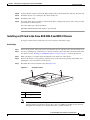
The ASA 5512-X, 5515-X, and 5525-X appliances ship with rack mount brackets installed on the front
of the chassis. If you want to mount the chassis to the back of the rack, you can move the brackets from
the front to the back of the chassis.
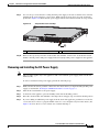
Detailed Steps
Step 1
(Optional) Move the brackets to the back of the chassis to install it in the back of the rack.
a.
Remove the rack-mount brackets from the chassis as shown in Figure 3-1.
Removing the Brackets from the Front of the Chassis
334560
Figure 3-1
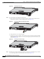
b.
Install the brackets on the back of the chassis by attaching the brackets to the holes in the chassis as
shown in Figure 3-2. After the brackets are secured to the chassis, you can rack-mount it.
Installing the Brackets on the Back of the Chassis
334561
Figure 3-2
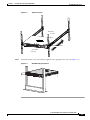
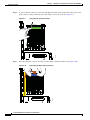
Step 2
We recommend that you install the chassis with the front bezel facing the cold aisle. (See Figure 3-3 for
an example of air flow from front to back.)
Cisco ASA 5500-X Series Hardware Installation Guide
3-2
Installing and Connecting the ASA 5500-X
Rack Mounting the Chassis
Figure 3-3
Airflow Direction
330840
HOT AISLE
Rear I/O
Cisco ASA
Adapative Security5545
Appliance
BOOT
ACTIVE
PS1
PS0
ALARM
VPN
HD1
HD0
1
AIR FLOW DIRECTION
0
COLD AISLE
Front Bezel
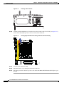
Step 3
Attach the chassis to the rack using the supplied screws appropriate for your rack (Figure 3-4).
Figure 3-4
Rack-Mounting the Chassis
334639
Chapter 3
Cisco ASA 5500-X Series Hardware Installation Guide
3-3
Chapter 3
Installing and Connecting the ASA 5500-X
Rack Mounting the Chassis
Rack Mounting the ASA 5500-X Chassis with Slide Rail Mounting System
The slide rail mounting system provides a quick, convenient, and secure method for rack mounting the
chassis. While the 5545-X and 5555-X chassis ship with the slide rail mounting system and can be
mounted using this system only, you can use the slide rail mounting system for any of the other
ASA 5500-X series chassis, as well.
•
Preparing the ASA 5512-X, ASA 5515-X, or ASA 5525-X to Use an Optional Slide Rail Rack
Mount System, page 3-4
•
Rack Mounting the Chassis with the Slide Rail Mounting System, page 3-5
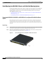
Preparing the ASA 5512-X, ASA 5515-X, or ASA 5525-X to Use an Optional Slide Rail Rack Mount
System
These instructions show how to prepare an ASA 5512-X, ASA 5515-X, or ASA 5525-X chassis for
mounting with the slide rail rack mount system. These chassis models ship with preinstalled fixed
rack-mount brackets, which must be replaced with the die-cast brackets that ship in the slide rail rack
mount kit.
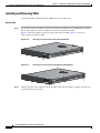
Detailed Steps
Step 1
From the slide rail rack mount kit, locate the two die-cast brackets, the six screws, and the four shoulder
screws that you need to prepare your chassis for installation in the side rail rack.
Step 2
Remove the preinstalled fixed rack-mount bracket on either side of the chassis by removing the three
bracket screws that hold each bracket in place. (See Figure 3-5.)
Figure 3-5
Remove Preinstalled Screws and Brackets on Either Side of Chassis
Cisco ASA 5500-X Series Hardware Installation Guide
3-4
Chapter 3
Installing and Connecting the ASA 5500-X
Rack Mounting the Chassis
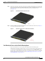
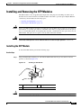
Step 3
Install a die-cast bracket to either side of the chassis by aligning and inserting the tab at the end of the
bracket into the hole on the chassis and then hinging it into position so that the bracket is flush with the
front face plate (bezel) of the chassis. Secure each bracket to the chassis with three screws.
(See Figure 3-6.)
Figure 3-6
Step 4
Install Die-Cast Brackets with Three Screws
Install two shoulder screws into the threaded hole locations on either side of the chassis (see Figure 3-7
for one side), and ensure that they are tight.
Figure 3-7
Install Two Shoulder Screws on Either Side of the Chassis
Rack Mounting the Chassis with the Slide Rail Mounting System
This section describes how to rack mount the chassis using the slide rail mounting system.
Although slide rail mounting is preferred, in the case of two-rail racks where the slide rails will not fit,
you can use the rack mounting brackets. You must order them separately (ASA-BRACKETS=). Note
that there will be a slight bend in the brackets when you attach them. For the procedure for attaching the
brackets to the front or back of the chassis, see the “Rack Mounting the ASA 5512-X, 5515-X, and
5525-X With Brackets” section on page 3-2.
Cisco ASA 5500-X Series Hardware Installation Guide
3-5
Chapter 3
Installing and Connecting the ASA 5500-X
Rack Mounting the Chassis
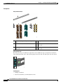
Prerequisites
Verify the Box Contents
A
C
D
E
F
300885
B
A
Slide Rails (x2) (preconfigured for square hole B
racks)
C
Round Hole Inserts for round hole racks (x4)
D
Threaded Hole Brackets for threaded hole
racks (x2)
E
Threaded Hole Standoffs for threaded hole
racks (x2)
F
Phillips pan-head screws for threaded hole
racks (x8)
Phillips flat-head screws for Inner Slide (x2)
Verify the Rack Type
330903
The slide rails are pre-assembled for square hole racks. Additional steps are required for round hole
racks and threaded hole racks. The following figure shows the slide rail with square hole rack inserts.
Tools Required
•
Phillips screwdriver
•
Flat-head screwdriver (for threaded hole racks)
Cisco ASA 5500-X Series Hardware Installation Guide
3-6
Chapter 3
Installing and Connecting the ASA 5500-X
Rack Mounting the Chassis
Detailed Steps
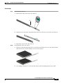
Step 1
Disassemble the slide rail.
a.
Pull the inner slide rail from the outer slide rail.
Front
Slide the plastic tab forward, and pull the inner slide rail to disconnect it from the outer slide rail.
c.
Repeat these steps for the other slide rail.
330908
b.
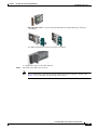
Attach the inner rails to the chassis.
a.
Align one of the inner slide rail key holes over the chassis shoulder screw on one side. Slide the inner
slide rail forward so that the shoulder screw is securely in place.
b.
Use a Phillips screwdriver to secure the inner slide rail with one Phillips flat-head screw (B).
330907
Step 2
Cisco ASA 5500-X Series Hardware Installation Guide
3-7
Chapter 3
Installing and Connecting the ASA 5500-X
330905
Rack Mounting the Chassis
Secure the other inner slide rail to the chassis by repeating the previous steps on this page.
330904
c.
(Round and Threaded Hole Racks Only) Customize the slide rails for round hole racks or threaded hole
racks.
a.
Using a Phillips head screwdriver, remove the square insert from the rear of the rail. Keep the two
Phillips head screws.
b.
Remove the square insert from the front of the rail. Keep the two Phillips head screws.
c.
(Round hole racks only) Align the round hole (C) insert to the rear of the rail, and secure it with two
of the saved screws.
d.
Align the round hole insert (C) or threaded hole bracket (D) to the front of the rail over the hooks.
330881
330882
330884
Step 3
– Round hole insert—Secure it with two of the saved screws.
Cisco ASA 5500-X Series Hardware Installation Guide
3-8
Installing and Connecting the ASA 5500-X
Rack Mounting the Chassis
330880
– Threaded hole insert—Secure it with the threaded hole standoff (E) using a flat-head
330878
screwdriver.
No additional hardware is necessary for the rear adapter.
330876
Chapter 3
e.
Step 4
Repeat these steps for the other slide rail.
Attach the outer slide rail to the rack.
Note
We recommend that you install the chassis with the front bezel facing the cold aisle. (See
Figure 3-3 for an example of air flow from front to back.)
Cisco ASA 5500-X Series Hardware Installation Guide
3-9
Chapter 3
Installing and Connecting the ASA 5500-X
Rack Mounting the Chassis
Figure 3-8
Airflow Direction
330840
HOT AISLE
Rear I/O
Cisco ASA
Adapative Security5545
Appliance
BOOT
ACTIVE
PS1
PS0
ALARM
VPN
HD1
HD0
1
AIR FLOW DIRECTION
0
COLD AISLE
Front Bezel
Round and Square Hole Racks
a.
Note
Align the front of one of the outer slide rails with the rack upright, push it forward, and click it into
place. Align the rear of the outer slide rail with the rack upright, pull the release tab, push the slide
rail toward the rack, release the tab, and click it into place.
For racks shorter than 24 inches in depth, remove the rear bracket with a Phillips head
screwdriver, pull the release tab, and adjust the slide rail to the appropriate length for the rack.
Front of
Rack
Rear of
Rack
330901
Rear of
Bracket
b.
Secure the other outer slide rail to the rack.
Cisco ASA 5500-X Series Hardware Installation Guide
3-10
Installing and Connecting the ASA 5500-X
330872
Rack Mounting the Chassis
Threaded Hole Racks
Align the slide rail to the front rack post. Secure it with two of the included Phillips pan-head screws
(F).
b.
Align the slide rail to the rear rack post. Secure it with two of the included Phillips pan-head screws
(F).
c.
Align the other slide rail to the rack.
330883
a.
330872
330875
Chapter 3
Step 5
Install the chassis.
a.
Align the inner slide rails to the outer slide rails. Install the inner slide rails into the outer slide rails
until they lock into place.
Cisco ASA 5500-X Series Hardware Installation Guide
3-11
Chapter 3
Installing and Connecting the ASA 5500-X
330889
Rack Mounting the Chassis
Pull the side release tabs to unlock the inner slide rail, and push the chassis assembly into the rack.
330898
b.
Secure the chassis to the rack with the front captive screws.
330890
Step 6
Cisco ASA 5500-X Series Hardware Installation Guide
3-12
Chapter 3
Installing and Connecting the ASA 5500-X
Connecting Cables, Turning on Power, and Verifying Connectivity
Connecting Cables, Turning on Power, and Verifying
Connectivity
This section describes how to connect the cables to the chassis and how to turn on the power.
Guidelines
Warning
Caution
Only trained and qualified personnel should install, replace, or service this equipment. Statement 49
Be sure to read the safety warnings in the Regulatory Compliance and Safety information document for
the ASA 5500-X and follow proper safety procedures when performing all tasks in this guide. See the
RCSI at http://www.cisco.com/en/US/docs/security/asa/hw/regulatory/compliance/asa5500x_rcsi.html.
The Cisco ASA 5500-X series hardware operates on AC power and supports the ability to restore the
previous power state of the system in the event that AC power is lost.
Earlier ASAs (V01) require you to turn on the power with the power switch. Newer ASAs (V02)
automatically turn on when you plug in the power cable. To determine your version, do one of the
following:
•
At the CLI, enter the show inventory command and look for V01 or V02 in the output.
•
On the back of the chassis, look at the VID PID label for V01 or V02.
For the V01 chassis, see the following limitations:
•
The ASA requires 50 seconds from the time that AC power is applied before the power state can be
updated and stored. This means that any changes to the power state within the first 50 seconds of
applying AC power will not be observed if AC power is removed within that time.
•
The ASA requires 10 seconds from the time it is placed into standby mode before the power state
can be updated and stored. This means any changes to the power state within the first 10 seconds of
entering standby mode (including the standby mode itself) will not be observed if AC power is
removed within that time.
For the V02 chassis, the above limitations to not apply.
Detailed Steps
Step 1
Place the chassis on a flat, stable surface, or in a rack (if you are rack-mounting it.)
Step 2
Connect the interface cables.
Cisco ASA 5500-X Series Hardware Installation Guide
3-13
Chapter 3
Installing and Connecting the ASA 5500-X
Connecting Cables, Turning on Power, and Verifying Connectivity
Network Management PC
1
2
3
4
Secured
Network
370600
Unsecured
Network
Console Management PC
1
(Optional) I/O Card. If you have a
fiber I/O card, you need to use SFP
modules (not included).
2
Management 0/0 interface (RJ-45)
3
Console port (RJ-45)
4
Gigabit Ethernet interfaces (RJ-45)
a.
Management 0/0 interface—For use with ASDM or CLI. You can connect the management PC
directly with an Ethernet cable, or connect the PC and the ASA to the same management network.
Make sure the PC is configured to obtain an IP address using DHCP.
Note
You can configure any interface to be a management-only interface using the
management-only command. You cannot disable management-only mode on the
management interface.
b.
(Optional) Console port—For use with the CLI. Connect the management PC or terminal server
using the included serial console cable. The console cable has a DB-9 connector on one end for the
serial port on your computer, and the other end is an RJ-45 connector. If your PC does not have a
serial port, you will need to obtain a DB-9-to-USB serial adapter.
c.
Gigabit Ethernet interfaces—For data networks. For the pre-installed network interfaces, use a
standard RJ-45 Ethernet cable. For the optional I/O card, use SFP modules. See the “Installing and
Removing the SFP Modules” section on page 4-11.
Note
You can use any unused Gigabit Ethernet interface on the ASA as the failover link. The
failover link interface is not configured as a normal networking interface; it should only be
used for the failover link. You can connect the failover link by using a dedicated switch with
no hosts or routers on the link or by using an Ethernet cable to link the units directly.
Cisco ASA 5500-X Series Hardware Installation Guide
3-14
Chapter 3
Installing and Connecting the ASA 5500-X
Connecting Cables, Turning on Power, and Verifying Connectivity
Step 3
Connect the power cord to the ASA, and connect the other end to your power source.
Step 4
For newer ASAs, the power turns on automatically when you plug in the power cable; do not press the
power button on the front panel.
For older ASAs, press the power button.
Step 5
Check the Power LED on the front of the ASA chassis. When it is solid green, the ASA is powered on.
Step 6
Check the Status LED on the front of the ASA chassis. When it is solid green, the ASA has passed
power-on diagnostics.
Cisco ASA 5500-X Series Hardware Installation Guide
3-15
Chapter 3
Connecting Cables, Turning on Power, and Verifying Connectivity
Cisco ASA 5500-X Series Hardware Installation Guide
3-16
Installing and Connecting the ASA 5500-X
CH A P T E R
4
Maintenance and Upgrade Procedures for the
ASA 5500-X
This chapter includes the following sections:
•
Removing and Replacing the Chassis Cover, page 4-1
•
Installing an I/O Card, page 4-3
•
Installing and Removing the SFP Modules, page 4-11
•
Removing and Installing the Power Supply, page 4-13
•
Installing and Removing the Solid State Drive for the ASA CX SSP, page 4-21
Removing and Replacing the Chassis Cover
This section describes how to remove and replace the chassis cover. This section includes the following
topics:
•
Removing the Chassis Cover, page 4-1
•
Replacing the Chassis Cover, page 4-2
Removing the Chassis Cover
To remove the chassis cover, perform the following steps.
Prerequisites
Read the Regulatory Compliance and Safety Information for the Cisco ASA 5500-X Series document.
Detailed Steps
Step 1
Warning
Power off the chassis.
Before working on a system that has an On/Off switch, turn OFF the power and unplug the power cord.
Statement 1
Cisco ASA 5500-X Series Hardware Installation Guide
4-1
Chapter 4
Maintenance and Upgrade Procedures for the ASA 5500-X
Removing and Replacing the Chassis Cover
Step 2
Turn the thumbscrew on the front of the chassis. See Figure 4-1. You may need to use a screwdriver if
the screw is too tight.
Note
Removing the chassis cover does not affect Cisco warranty. Upgrading the ASA does not require
any special tools and does not create any radio frequency leaks.
Figure 4-1
Removing the Chassis Cover
282506
1
1
Thumbscrew
Step 3
With the rear of the chassis facing you, pull the chassis cover forward then lift the cover up. (See
Figure 4-1.)
Step 4
Place the cover in a safe place.
Replacing the Chassis Cover
Caution
Do not operate the ASA without the chassis cover installed. The chassis cover protects the internal
components, prevents electrical shorts, and provides proper air-flow for cooling the electronic
components.
To replace the chassis cover, perform the following steps.
Detailed Steps
Step 1
Place the chassis on a secure surface with the front panel facing you.
Step 2
Lower the front of the chassis cover onto the chassis, slide it forward until it fits into place, and tighten
the thumbscrew to secure the chassis cover. (See Figure 4-2.)
Cisco ASA 5500-X Series Hardware Installation Guide
4-2
Chapter 4
Maintenance and Upgrade Procedures for the ASA 5500-X
Installing an I/O Card
Figure 4-2
Replacing the Chassis Cover
282616
1
1
Thumbscrew
Step 3
Reinstall the chassis on a rack.
Step 4
Reinstall the network interface cables.
Step 5
Power on the chassis.
Installing an I/O Card
•
Installing an I/O Card in the Cisco ASA 5512-X, 5515-X, and 5525-X Chassis, page 4-3
•
Installing an I/O Card in the Cisco ASA 5545-X and 5555-X Chassis, page 4-7
Installing an I/O Card in the Cisco ASA 5512-X, 5515-X, and 5525-X Chassis
To remove an existing I/O card and install a new one, perform the following steps.
Detailed Steps
Step 1
Power off the chassis, remove the power cable from the chassis, and remove the chassis from the rack.
Step 2
Locate a grounding strap, and fasten it to your wrist so that it contacts bare skin. Attach the other end to
the chassis. See the “Working in an ESD Environment” section on page 2-3 for more information.
Step 3
With a Phillips head screwdriver, loosen the captive installation screw on the rear of the chassis
Step 4
Remove the chassis cover by placing your hand on top of the chassis lid, pressing down firmly, and
pushing the cover toward the rear of the chassis.
Step 5
Determine the location of the I/O card. (See Figure 4-3.)
Cisco ASA 5500-X Series Hardware Installation Guide
4-3
Chapter 4
Maintenance and Upgrade Procedures for the ASA 5500-X
Installing an I/O Card
Figure 4-3
I/O Card Location
1
282498
2
Caution
Step 6
1
I/O Card holder
2
Power supply
You must disconnect the blue Regex flexible circuit connector from the motherboard before removing
the I/O card from the chassis. The copper-colored Regex flexible circuit can break during the I/O card
removal or installation process, so handle it with care.
To expose the blue connector of the Regex flexible circuit, push down on the center of the green
connector clamp, and lift the right end of the clamp to release the lock. (See Figure 4-4.)
Figure 4-4
Removing the Connector Clamp
-A-
-B-A-
-B-
-B-C-
PUSH AND LIFT TAB
331359
-B-
Step 7
Disconnect the blue Regex cable connector from the motherboard by lifting carefully but firmly. (See
Figure 4-5.)
Cisco ASA 5500-X Series Hardware Installation Guide
4-4
Maintenance and Upgrade Procedures for the ASA 5500-X
Installing an I/O Card
Figure 4-5
Removing the Regex Cable Connector
-A-
-B-A-
-B-
-B-C-
-B-
331355
Chapter 4
Step 8
Caution
Lift the I/O card out of the chassis with both hands by placing an index finger into each of the card cover
vents and placing your thumbs on the edge of the card cover. (See Figure 4-6 on page 4-6.) Use firm
upward pressure and a gentle rocking motion, as the card is firmly seated.
Keep hands clear of all electronics underneath the card cover.
Cisco ASA 5500-X Series Hardware Installation Guide
4-5
Chapter 4
Maintenance and Upgrade Procedures for the ASA 5500-X
Installing an I/O Card
Figure 4-6
Lift the I/O Card Upward to Release it
2
1
2
331354
1
Step 9
1
Index finger placement
2
Thumb placement
Insert the new I/O card into the chassis. (See Figure 4-7.) The I/O card fits properly if the following
criteria are met:
a.
The PCIe bus is properly inserted on the motherboard
b.
The small black plastic guide slides all the way into the chassis
c.
The two hooks on the assembly plug into the two slots on the edge of the chassis
Installing the I/O Card
331399
Figure 4-7
Cisco ASA 5500-X Series Hardware Installation Guide
4-6
Chapter 4
Maintenance and Upgrade Procedures for the ASA 5500-X
Installing an I/O Card
Step 10
Connect the blue connector end of the Regex ribbon cable to the motherboard, and close the green tab.
Step 11
Install the chassis cover, and replace the chassis in the rack.
Step 12
Install the power cable.
Step 13
For newer ASAs, the power turns on automatically when you plug in the power cable; do not press the
power button on the front panel.
For earlier ASAs, press the power button.
The LEDs will blink when traffic begins to pass through.
Installing an I/O Card in the Cisco ASA 5545-X and 5555-X Chassis
To replace an I/O card in an ASA 5545-X or 5555-X chassis, follow these steps.
Detailed Steps
Step 1
Power off the chassis, remove the power cable from the chassis, and remove the chassis from the rack.
Step 2
Locate a grounding strap, and fasten it to your wrist so that it contacts bare skin. Attach the other end to
the chassis. See the “Working in an ESD Environment” section on page 2-3 for more information.
Step 3
With your fingers, loosen the captive installation screw on the rear of the chassis.
Step 4
Remove the chassis cover by placing your hand on top of the chassis lid, pressing down firmly, and
pushing the cover toward the rear of the chassis.
Step 5
Determine the location of the I/O card. (See Figure 4-8.)
Figure 4-8
I/O Card Location
2
282498
1
1
I/O Card holder
2
Power supply
Note
You must disconnect the blue Regex flexible circuit connector from the motherboard before
removing the I/O card from the chassis. The copper-colored Regex flexible circuit can break
during the I/O card removal or installation process, so handle it with care.
Cisco ASA 5500-X Series Hardware Installation Guide
4-7
Chapter 4
Maintenance and Upgrade Procedures for the ASA 5500-X
Installing an I/O Card
To expose the blue connector on the end of the Regex flexible circuit, push down on the center of the
green connector clamp, and lift the end of the clamp to release the lock. (See Figure 4-9.)
Figure 4-9
Removing the Connector Clamp
PUSH AND LIFT TAB
-A-
Step 6
-C-
-B-
-B-A-
-B-
331353
-B-
Disconnect the blue connector from the board by lifting carefully but firmly. (See Figure 4-10.)
Removing the Regex Cable Connector
-B-
Figure 4-10
-A-
Step 7
-C-B-
-A-B-
331350
-B-
Cisco ASA 5500-X Series Hardware Installation Guide
4-8
Maintenance and Upgrade Procedures for the ASA 5500-X
Installing an I/O Card
Step 8
Lift the I/O card out of the chassis with both hands by placing an index finger into each of the card cover
vents and placing a thumb on the edge of the card cover. (See Figure 4-11.) Use firm upward pressure
and a gentle rocking motion, as the card is firmly seated.
Figure 4-11
Lift the I/O Card Upward to Release it
1
2
1
2
331354
Chapter 4
Step 9
1
Index finger placement
2
Thumb placement
Insert the new I/O card into the chassis. (See Figure 4-12.)
The I/O card holder fits properly if the following criteria are met:
a.
The PCIe bus is properly inserted on the motherboard.
b.
The small black plastic guide slides all the way into the chassis.
c.
The two hooks on the assembly plug into the two slots on the edge of the chassis.
Cisco ASA 5500-X Series Hardware Installation Guide
4-9
Chapter 4
Maintenance and Upgrade Procedures for the ASA 5500-X
Installing an I/O Card
Inserting a New I/O Card
330134
Figure 4-12
Carefully feed the flexible Regex circuit into the yellow channel on the chassis side (see Figure 4-13),
and reconnect the blue Regex cable connector end to the motherboard.
Feeding Regex Flexible Circuit through Channel and Reconnecting
-B-
Figure 4-13
-A-
Step 10
-C-B-
-A-B-
331351
-B-
Step 11
Close the green connector clamp.
Step 12
Install the chassis cover, and replace the chassis in the rack.
Step 13
Install the power cable, and restore power to the chassis. The LEDs will blink when traffic begins to pass
through.
Cisco ASA 5500-X Series Hardware Installation Guide
4-10
Chapter 4
Maintenance and Upgrade Procedures for the ASA 5500-X
Installing and Removing the SFP Modules
Installing and Removing the SFP Modules
The SFP module is a hot-swappable input/output device that plugs into the SFP ports. This section
describes how to install and remove the SFP modules in the ASA to provide optical Gigabit Ethernet
connectivity, and it includes the following topics:
Caution
Warning
•
Installing the SFP Module, page 4-11
•
Removing the SFP Module, page 4-12
Protect your SFP modules by inserting clean dust plugs into the SFPs after the cables are extracted from
them. Be sure to clean the optic surfaces of the fiber cables before you plug them back into the optical
bores of another SFP module. Avoid getting dust and other contaminants into the optical bores of your
SFP modules. The optics do not operate correctly when obstructed with dust.
Because invisible laser radiation may be emitted from the aperture of the port when no cable is
connected, avoid exposure to laser radiation and do not stare into open apertures. Statement 70
Installing the SFP Module
To install the SFP module, perform the following steps.
Detailed Steps
Step 1
Align the SFP module with the port, and slide the SFP module into the port slot until it locks into
position, as shown in Figure 4-14.
Figure 4-14
Installing an SFP Module
3
132985
2
1
Caution
1
Optical port plug
3
SFP module
2
SFP port slot
Do not remove the optical port plugs from the SFP until you are ready to connect the cabling.
Cisco ASA 5500-X Series Hardware Installation Guide
4-11
Chapter 4
Maintenance and Upgrade Procedures for the ASA 5500-X
Installing and Removing the SFP Modules
Step 2
Remove the optical port plug, and then connect the network cable to the SFP module.
Step 3
Connect the other end of the cable to your network.
Removing the SFP Module
SFP modules use various latch designs to secure the SFP modules in the SFP ports. The following list
includes the different module design types:
Note
•
Mylar Tab Module
•
Actuator/Button SFP Module
•
Bale-Clasp SFP Module
•
Plastic Collar Module
Latch designs are not linked to SFP model or technology types. For information about SFP models and
technology types, see the label on the side of your SFP.
To remove the SFP module, perform the following steps.
Detailed Steps
Step 1
Warning
Caution
Step 2
Disconnect all cables from the SFP.
Because invisible laser radiation may be emitted from the aperture of the port when no cable is
connected, avoid exposure to laser radiation and do not stare into open apertures. Statement 70
Do not pull on the cabling in an attempt to remove the SFP.
Disconnect your particular SFP latch, as shown in Figure 4-15.
Figure 4-15
Disconnecting SFP Latch Mechanisms
1
2
3
4
A
117722
B
1
Mylar tab
2
Actuator/Button
3
Bale-clasp
4
Plastic collar
Cisco ASA 5500-X Series Hardware Installation Guide
4-12
Chapter 4
Maintenance and Upgrade Procedures for the ASA 5500-X
Removing and Installing the Power Supply
Step 3
Grasp the SFP on both sides, and remove it from the port.
Removing and Installing the Power Supply
•
Removing and Installing the AC Power Supply, page 4-13
•
Installing the DC Input Power, page 4-15
•
Removing and Installing the DC Power Supply, page 4-19
Removing and Installing the AC Power Supply
Caution
If you remove a power supply, replace it immediately to prevent disruption of service.
Caution
If the appliance is subjected to environmental overheating, it shuts down and you must manually power
cycle it to turn it on again.
Warning
This unit has more than one power supply connection; all connections must be removed completely
to completely remove power from the unit. Statement 102
Warning
This product relies on the building’s installation for short-circuit (overcurrent) protection. Ensure that
the protective device is rated not greater than: 120 VAC, 20A U.S. (240 VAC, 10A international).
Statement 1005
Note
This procedure applies only to the appliances with a removable AC power supply (ASA 5545-X and ASA
5555-X). If only one power supply is installed, make sure that it is installed in slot 0 (left slot) and that
slot 1 (right slot) is covered with a slot cover.
To remove and install the AC power supply, follow these steps:
Step 1
If you are adding an additional power supply, from the back of the appliance, push the lever on the slot
cover to the left to release it, grasp the handle of the slot cover and pull it away from the chassis. (See
Figure 4-16.) Save the slot cover for future use. Continue with Step 3.
Cisco ASA 5500-X Series Hardware Installation Guide
4-13
Chapter 4
Maintenance and Upgrade Procedures for the ASA 5500-X
Removing and Installing the Power Supply
Removing the Slot Cover
331088
Figure 4-16
Step 2
If you are replacing a power supply, follow these steps:
a.
Power off the appliance.
b.
From the back panel of the appliance, unplug the power supply cable.
c.
Push the lever on the power supply to the left and remove the power supply by grasping the handle
and then pulling the power supply away from the chassis while supporting it from beneath with the
other hand. (See Figure 4-17.) Continue with Step 3.
Removing the AC Power Supply
331089
Figure 4-17
Step 3
Install the new power supply by aligning it with the power supply bay and pushing it into place until it
is seated while supporting it from beneath with the other hand. (See Figure 4-18.)
Installing the AC Power Supply
331086
Figure 4-18
Cisco ASA 5500-X Series Hardware Installation Guide
4-14
Chapter 4
Maintenance and Upgrade Procedures for the ASA 5500-X
Removing and Installing the Power Supply
Step 4
Connect the power cable. If you are installing two power supplies for a redundant configuration, plug
each one into a power source (we recommend a UPS).
Step 5
Power on the appliance if you powered it off to replace the only power supply.
Step 6
Check the PS0 and PS1 indicators on the front panel to make sure they are green. On the back panel of
the appliance, make sure the power supply indicator on the bottom of each installed power supply is
green. (See Figure 4-19.)
Back Power Supply Indicators
PS0
PS1
331087
Figure 4-19
Installing the DC Input Power
Warning
The covers are an integral part of the safety design of the product. Do not operate the unit without the
covers installed. Statement 1077
Warning
When you install the unit, the ground connection must always be made first and disconnected last.
Statement 1046
Warning
Before performing any of the following procedures, ensure that power is removed from the DC circuit.
Statement 1003
Warning
Only trained and qualified personnel should be allowed to install, replace, or service this equipment.
Statement 1030
Cisco ASA 5500-X Series Hardware Installation Guide
4-15
Chapter 4
Maintenance and Upgrade Procedures for the ASA 5500-X
Removing and Installing the Power Supply
Warning
This product relies on the building’s installation for short-circuit (overcurrent) protection. Ensure that
the protective device is rated not greater than: 80 VAC, 20A. Statement 1005
The DC power supply is shipped installed in the chassis, either one or two power supplies depending on
which configuration you ordered. You must connect the power supply wires. This section describes how
to install the DC power supply ground leads and input power leads to the appliance DC input power
supply. Before you begin, read these important notices:
•
The color coding of the DC input power supply leads depends on the color coding of the DC power
source at your site. Typically, green or green/yellow is used for ground (GND), black is used for –48
V on the negative (–) terminal, and red is used for RTN on the positive (+) terminal. Ensure that the
lead color coding you choose for the DC input power supply matches the lead color coding used at
the DC power source.
•
Make sure that the chassis ground is connected on the chassis before you begin installing the DC
power supply. See “Working in an ESD Environment” section on page 2-3 for more information.
Figure 4-20 shows the back panel of the ASA 5512-X, ASA 5515-X, and ASA 5525-X with the DC
power supply.
ASA 5512-X, ASA 5515-X, and ASA 5525-X Back Panel
333226
Figure 4-20
1
1
2
Fixed fan
2
Fixed DC power supply
Figure 4-21 shows the back panel of the ASA 5545-X and ASA 5555-X with two DC power supplies.
ASA 5545-X and ASA 5555-X Back Panel
333059
Figure 4-21
Cisco ASA 5500-X Series Hardware Installation Guide
4-16
Maintenance and Upgrade Procedures for the ASA 5500-X
Removing and Installing the Power Supply
Note
If only one power supply is installed, make sure that it is installed in slot 0 (left slot) and that slot 1 (right
slot) is covered with a slot cover.
To connect the DC power supply on the appliance, follow these steps:
Step 1
Make sure that the chassis ground is connected on the chassis before you begin installing the DC power
supply.
Step 2
Turn off the circuit breaker to the power supply.
Step 3
From the front of the appliance, verify that the power switch is in the Standby position.
Step 4
Move the circuit-breaker switch handle to the Off position, and apply tape to hold it in the Off position.
Step 5
Use a 10 gauge wire-stripping tool to strip each of the three wires coming from the DC input power
source. Strip the wires to 0.27 inch (7 mm) + 0.02 inch (0.5 mm). Do not strip more than the
recommended length of wire because doing so could leave the wire exposed from the DC power supply
connection. (See Figure 4-22.)
Figure 4-22
Stripping the DC Input Power Source Wire
1
333062
Chapter 4
1
Warning
Step 6
We recommend that you strip the wire to 0.27 inch (7 mm).
An exposed wire lead from a DC input power source can conduct harmful levels of electricity. Be sure
that no exposed portion of the DC input power source wire extends from the terminal block plug.
Statement 122
Identify the positive, negative, and ground feed positions for the DC power supply connection. The
recommended wiring sequence is as follows (see Figure 4-23 on page 4-18):
•
Ground lead wire (middle)
•
Positive (+) lead wire (left)
•
Negative (–) lead wire (right)
Cisco ASA 5500-X Series Hardware Installation Guide
4-17
Chapter 4
Maintenance and Upgrade Procedures for the ASA 5500-X
Removing and Installing the Power Supply
Figure 4-23
Ground Wires
3
2
333057
1
1
Negative (–) lead wire
3
Positive (+) lead wire
2
Ground lead wire
Figure 4-24 shows the DC power supply with lead wires.
DC Power Supply with Lead Wires
333060
Figure 4-24
Step 7
Insert the exposed end of one of the ground wires into the inlet on the DC power supply. After you push
in the wires, they are held in place with a spring, which makes the physical contact. Make sure that you
cannot see any wire lead. Only wires with insulation should extend from the DC power supply.
Step 8
Repeat Step 5 through Step 7 for the remaining two DC input power source wires, the positive lead wire
and the negative lead wire.
Cisco ASA 5500-X Series Hardware Installation Guide
4-18
Chapter 4
Maintenance and Upgrade Procedures for the ASA 5500-X
Removing and Installing the Power Supply
Step 9
Use a tie wrap to secure the wires coming from the power supply to the rack so that the wires cannot be
pulled from the power supply by casual contact. Make sure the tie wrap allows for some slack in the
ground wire. Figure 4-25 shows the DC power supply with the wires inserted and the tie wrap secured.
Complete DC Secure Tie Wrap
333061
Figure 4-25
1
1
Step 10
Lead wires secured with a tie wrap
Remove the tape (if any) from the circuit breaker switch handle, and move the circuit breaker switch
handle to the On position. The power supply indicators light up when power is supplied to the appliance.
Removing and Installing the DC Power Supply
Note
This procedure applies only to the appliances with a removable DC power supply (ASA 5545-X and
ASA 5555-X).
To remove and install a DC power supply, perform the following steps:
Step 1
Make sure that the chassis ground is connected on the chassis before you begin installing the DC power
supply, as described in “Working in an ESD Environment” section on page 2-3.
Step 2
Turn off the circuit breaker to the power supply.
Step 3
At the back of the appliance, place the Standby switch into the Standby position.
Step 4
Move the circuit-breaker switch handle to the Off position, and apply tape to hold it in the Off position.
Step 5
If you are adding an additional power supply, from the back of the appliance, push the lever on the slot
cover to the left to release it, grasp the handle of the slot cover, and pull it away from the chassis. (See
Figure 4-26.) Save the slot cover for future use. Continue with Step 7.
Cisco ASA 5500-X Series Hardware Installation Guide
4-19
Chapter 4
Maintenance and Upgrade Procedures for the ASA 5500-X
Removing and Installing the Power Supply
Removing the Slot Cover
333063
Figure 4-26
Step 6
If you are replacing a power supply, follow these steps:
a.
Remove the wires from the DC power supply by inserting a small flat-head screwdriver into the
square hole above the wire to relieve the spring pressure. (See Figure 4-27.)
Removing the Wires from the DC Power Supply
333225
Figure 4-27
b.
Gently pull the wires out of the power supply.
c.
Push the lever on the power supply to the left and remove the power supply by grasping the handle
and then pulling the power supply out of the chassis while supporting it from beneath with the other
hand. (See Figure 4-28.)
Removing the DC Power Supply
333224
Figure 4-28
Step 7
Install the new power supply by lining it up with the power supply bay and pushing it into place until it
is seated while supporting it from beneath with the other hand. (See Figure 4-29.)
Cisco ASA 5500-X Series Hardware Installation Guide
4-20
Chapter 4
Maintenance and Upgrade Procedures for the ASA 5500-X
Installing and Removing the Solid State Drive for the ASA CX SSP
Installing the DC Power Supply
333064
Figure 4-29
Step 8
To connect the DC input power source wires, see Step 5 though Step 10 in Installing the DC Input Power,
page 4-15.
Installing and Removing the Solid State Drive for the
ASA CX SSP
This section describes how to install and remove the Solid State Drive (SSD) in the ASA 5500-X series
security appliances, and contains the following topics:
•
Installation Scenarios, page 4-21
•
Installing and Removing SSDs, page 4-22
Installation Scenarios
Caution
Make sure that you replace a failed SSD as soon as possible to avoid data loss. Removal of all SSDs shuts
down the ASA CX service.
You may need to install, remove, or replace a SSD in your ASA 5500-X series ASA under the following
conditions:
•
If you are adding the ASA CX SSP to an existing ASA for the first time, after you have installed the
SSD in the ASA, you must reload the ASA and then reimage the ASA CX SSP.
•
If the drive fails in the single-drive models or both drives fail simultaneously in the dual-drive
models, you need to replace the drives. ASA CX SSP shuts down when this happens, so CX features
are not available as part of the recovery process. You must reload the ASA and then reimage the ASA
CX SSP.
•
If a single drive fails in the dual-drive model, you can hot-swap the failed drive. In this case, ASA
CX SSP does not shut down and you do not need to reload the ASA.
•
If you want to replace a drive that is still functioning. Back up and gracefully shut down the ASA
CX SSP before replacing the drive. You must reload the ASA and then reimage the ASA CX SSP.
Cisco ASA 5500-X Series Hardware Installation Guide
4-21
Chapter 4
Maintenance and Upgrade Procedures for the ASA 5500-X
Installing and Removing the Solid State Drive for the ASA CX SSP
Installing and Removing SSDs
To install and remove SSDs in the ASA 5500-X series, follow these steps.
Detailed Steps
Step 1
If you need to remove an old drive, from the front panel of the ASA, remove the SSD by pressing the
button on the right side of the bay until the lever is released. Pull out the SSD.
Figure 4-30 shows the ASA 5512/5515/5525-X models with one SSD. Figure 4-31 shows the
ASA 5545/5555-X with two SSDs.
Removing the SSD from the ASA 5512/5515/5525-X
Figure 4-31
Removing the SSD from the ASA 5545-X and ASA 5555-X
334566
334566
Figure 4-30
Step 2
On the front panel of the appliance, line up the SSD carrier with the SSD bay and push it in until it is
seated. Push the lever into place.
Cisco ASA 5500-X Series Hardware Installation Guide
4-22
Maintenance and Upgrade Procedures for the ASA 5500-X
Installing and Removing the Solid State Drive for the ASA CX SSP
Figure 4-32 shows the ASA 5512/5515/5525-X models. Figure 4-33 shows the ASA 5545/5555-X
models.
Installing the SSD in the ASA 5512/5515/5525-X
Figure 4-33
Installing the SSD in the ASA 5545-X and ASA 5555-X
334634
Figure 4-32
334565
Chapter 4
Step 3
On the front panel of the ASA, make sure the HDD1(top SSD) and HDD0 (bottom SSD) indicators are
solid green to indicate that the SSDs are now active.
Step 4
If you replaced the drive in the ASA 5512-X, ASA 5515-X, or ASA 5525-X, you need to reinstall the
ASA CX using the ASA CX boot image. For more information refer to Cisco ASA CX Module Quick
Start Guide found at this URL:
http://www.cisco.com/en/US/docs/security/asa/quick_start/cx/cx_qsg.html
If you replaced the drives in the ASA 5545-X and ASA 5555-X, the ASA rebuilds the data on the SSD
because it is configured to be in RAID1.
Cisco ASA 5500-X Series Hardware Installation Guide
4-23
Chapter 4
Installing and Removing the Solid State Drive for the ASA CX SSP
Cisco ASA 5500-X Series Hardware Installation Guide
4-24
Maintenance and Upgrade Procedures for the ASA 5500-X
INDEX
see ESD
Numerics
equipment racks
1000 W power supplies
power cords (table)
tips
2-5
2-6
ESD
preventing
2-3
A
F
AC-input power cords
product numbers (table)
2-5
ASA CX SSP
failover
3-14
fans
solid state drive
illustration
ventilation
2-6
1-3
installing
4-22
removing
4-22
H
hardware specifications
1-15
C
I
chassis covers
removing
4-1
replacing
4-2
circuit breaker warning
Cisco warranty
Console port
I/O card
replacing in an ASA 5512-X, 5515-X, 5525-X
4-13, 4-16
2-2
replacing in an ASA 5545-X, 5555-X
4-3
4-7
interface cables
3-14
auxiliary port
connecting
3-13
console port
D
3-14
3-14
data sheet
5512-X and 5515-X
P
1-16
5525-X, 5545-X, 5555-X
1-16
panel
removing
E
4-2
power supplies
considerations
electrostatic discharge
described
1-13, 3-13
1-13
Cisco ASA 5500-X Series Hardware Installation Guide
IN-1
Index
illustrations
indicator
1-14
1-14
power supplies (AC)
installing
4-13
removing
4-13
power supplies (DC)
connecting
4-17
installing
4-19
removing
4-19
R
rack mounting
5512-X, 5515-X, 5525-X
5545-X, 5555-X
3-2
3-4
RJ-45 connector
pinouts
1-18
S
safety
2-2
SFP module
cabling requirements
1-5
installing and removing
supported modules
site environment
4-11
1-5
2-3
V
ventilation fans
2-6
W
warning
circuit breaker
4-13, 4-16
exposed DC wire
warranty
4-17
2-2
Cisco ASA 5500-X Series Hardware Installation Guide
IN-2