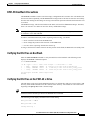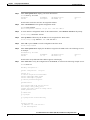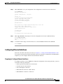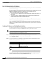
1
C H A P T E R
5
Configuring the MGX RPM-PR
This chapter describes how to complete a basic configuration of the MGX Route Processor Module
(RPM-PR). It provides procedures for configuring ATM, Ethernet, and Fast Ethernet interfaces, as well
as, permanent virtual circuits (PVCs). It also details how to make connections between an RPM-PR and
a PXM-45 and between other service modules or other RPM-PRs. The chapter contains the following
sections:
•
Accessing the RPM-PR Command Line Interface
•
Booting the RPM-PR
•
Verifying the Configuration
•
Establishing 1:N Redundancy Between Two or More RPM-PR Cards
This chapter provides information necessary to get the RPM-PR up and running. Detailed command
information is available in the Cisco IOS command reference publications.
Note
The back cards used in conjunction with the RPM-PR are equivalent to port adapters in Cisco routers.
Accessing the RPM-PR Command Line Interface
To configure the RPM-PR, you must access the command line interface (CLI) of the RPM-PR.
The RPM-PR CLI can be accessed using any of the following methods:
•
Console port on the front of the RPM-PR
The RPM-PR has an RJ-45 connector on the front of the card module. If you configure the RPM-PR
on site, connect a console terminal (an ASCII terminal or a PC running terminal emulation software)
directly to the console port on your RPM-PR using an RS-232 to RJ-45 rollover cable for CLI access
(see Chapter 3, “Installing the MGX RPM-PR”).
•
cc from another MGX 8850 or MGX 8950 card
After initial configuration, you can also configure the RPM-PR through the PXM-45. You access the
RPM-PR CLI by entering the cc (change card) command from any of the other cards in the switch.
•
Telnet from a workstation, PC, or another router
After initial configuration, you can also configure the RPM-PR remotely via Telnet. After the
RPM-PR is installed and has PVCs to other RPM-PRs or routers in the network, you can Telnet to
access the RPM-PR CLI remotely from these other devices.
Cisco MGX Route Processor Module (RPM-PR) Installation and Configuration Guide
Release 2.1, Part Number 78-12510-02 Rev. C1, August 31, 2004
5-1
Chapter 5
Configuring the MGX RPM-PR
Booting the RPM-PR
To connect a modem to the auxiliary port on the RPM-PR, see Chapter 3, “Installing the MGX
RPM-PR.”
Booting the RPM-PR
When the RPM-PR is booted, the boot image must be the first file in the bootflash. If the bootflash does
not have a valid boot image as a first file, the card may not be able to boot and can result in bootflash
corruption. If the bootflash is corrupted, you will have to send the card back for an external burn with a
valid boot image.
You can reboot the RPM-PR from the PXM by entering the command resetcd <card_number> from the
switch CLI, where card_number is the slot number of the RPM-PR that is being rebooted.
Note
Omitting the card number resets the entire system.
Also, you can reboot the RPM-PR from the RPM-PR using the RPM-PR console port and entering the
reload command.
Each time you turn on power to the RPM-PR, by inserting the RPM-PR into the MGX 8850 or the
MGX 8950, it goes through the following boot sequence:
1.
The RPM-PR runs diagnostics on the CPU, memory, and interfaces.
2.
The system boot software, which is the boot image, executes and searches for a valid Cisco IOS
image, which is the RPM-PR runtime software.
The source of the Cisco IOS image is determined by the configuration register setting. To verify this
setting, you can enter either the show version or show bootvar command. (See the “Viewing the
Hardware Configuration” section later in this chapter.)
•
If the configuration register is set to the factory-default setting of 0x01, RPM-PR will come up and
stay in boot mode.
•
If the configuration register is 0x2, the RPM-PR will look for the runtime image either in bootflash
or on the PXM C:FW drive.
3.
The search for runtime image is determined by which boot system command is entered.
•
Entering the boot system x:<runtime_image_name> command will result in a search for a runtime
image on the PXM C:FW drive.
•
Entering the boot system bootflash:<runtime_image_name> command will result in a search for a
run time image in the bootflash.
4.
If the runtime software is not found after three attempts, the RPM-PR reverts to the boot mode.
5.
If a valid Cisco IOS image is found, then the RPM-PR searches for a valid configuration, which can
reside in NVRAM or as a configuration file either on the PXM hard disk x: drive or in bootflash.
If you want to load from a specific configuration file, you should enter either the
boot config bootflash:<config_file> command or the boot config x:<config_file> command.
6.
For normal RPM-PR operation, there must be a valid Cisco IOS image on the PXM-45 x: drive or
in bootflash, and a configuration in NVRAM or configuration file in bootflash or on the PXM disk.
The first time you boot the RPM-PR, configure the RPM-PR interfaces and save the configuration
to a file in NVRAM. Then follow the procedure described in “Initializing the RPM-PR Card.” For
information on the Cisco IOS instructions, see Appendix C, “IOS and Configuration Basics.”
5-2
Cisco MGX Route Processor Module (RPM-PR) Installation and Configuration Guide
Release 2.1, Part Number 78-12510-02 Rev. C1, August 31, 2004
Chapter 5
Configuring the MGX RPM-PR
Booting the RPM-PR
RPM-PR Bootflash Precautions
The RPM-PR bootflash is used to store boot image, configuration and “run time” files. The Flash stores
and accesses data sequentially, and the RPM-PR boot image must be the first file stored to successfully
boot the card. Erasing the boot image or moving it from the first position on the Flash will cause the card
to not boot.
The RPM boot image, which comes loaded on the Flash, will work for all RPM IOS images. Therefore,
there is no reason to ever delete or move the factory installed boot image.
Note
Erasing or moving the boot image can cause RPM-PR boot failure. When this happens, the RPM must
be returned to Cisco and reflashed.
In order to avoid this unnecessary failure, requiring card servicing, you should
•
Never erase the boot file from the RPM Flash
•
Never change the position of the boot file on the RPM Flash
•
Use care when “squeezing” the Flash to clean it up.
As long as the boot file remains intact in the first position on the flash, the RPM will successfully boot.
Verifying the IOS Files on Bootflash
Enter the show bootflash command to verify the IOS files on the bootflash. The following screen
displays the RPM-PR command sequence.
Router#show bootflash:
-#1
2
3
ED
..
..
..
--type-image
config
config
--crc--- -seek-- nlen -length- -----date/time-----AB6CF374 2BAFB4
11 2600756 Jul 25 2001 02:41:41
44E48EC2 34712C
18
573685 Aug 07 2001 23:03:42
7B53E8DC 40E368
18
815547 Aug 08 2001 19:28:03
name
rpm-boot-mz
auto_config_slot16
auto_config_slot15
28777624 bytes available (3990376 bytes used)
Router#
Verifying the IOS Files on the PXM-45 x: Drive
The IOS image can be stored on the PXM-45 hard drive. To confirm this, make sure you are in the C:FW
directory. Enter the ll command to list the contents of the directory. You should see a file with a name
beginning with rpm-js-mz, which is the IOS image.
Tip
Copy the RPM-PR Cisco IOS image into the RPM C: directory (not the E: directory) of the PXM-45
hard disk with the filename specified in the RPM-PR boot command.
The following screen displays the PXM C:FW content listing.
M8850_LA.8.PXM.a > cd FW
M8850_LA.8.PXM.a > ll
Listing Directory .:
Cisco MGX Route Processor Module (RPM-PR) Installation and Configuration Guide
Release 2.1, Part Number 78-12510-02 Rev. C1, August 31, 2004
5-3
Chapter 5
Configuring the MGX RPM-PR
Booting the RPM-PR
drwxrwxrwx
drwxrwxrwx
-rwxrwxrwx
-rwxrwxrwx
-rwxrwxrwx
-rwxrwxrwx
-rwxrwxrwx
-rwxrwxrwx
-rwxrwxrwx
-rwxrwxrwx
-rwxrwxrwx
-rwxrwxrwx
-rwxrwxrwx
-rwxrwxrwx
-rwxrwxrwx
-rwxrwxrwx
-rwxrwxrwx
-rwxrwxrwx
-rwxrwxrwx
-rwxrwxrwx
-rwxrwxrwx
-rwxrwxrwx
-rwxrwxrwx
-rwxrwxrwx
-rwxrwxrwx
-rwxrwxrwx
-rwxrwxrwx
-rwxrwxrwx
-rwxrwxrwx
-rwxrwxrwx
-rwxrwxrwx
1
1
1
1
1
1
1
1
1
1
1
1
1
1
1
1
1
1
1
1
1
1
1
1
1
1
1
1
1
1
1
0
0
0
0
0
0
0
0
0
0
0
0
0
0
0
0
0
0
0
0
0
0
0
0
0
0
0
0
0
0
0
0
0
0
0
0
0
0
0
0
0
0
0
0
0
0
0
0
0
0
0
0
0
0
0
0
0
0
0
0
0
0
13312
13312
2253552
10655280
3350304
1431512
1030532
891552
303936
641312
743136
826392
10528336
7939476
1160328
468388
1245112
4069552
737896
2490064
3674368
838840
742168
297988
264592
3111904
744600
3267520
248686
4135448
4135000
May
May
May
Apr
Apr
May
May
May
May
May
May
May
May
May
May
May
May
May
May
May
May
May
May
May
May
May
May
May
May
May
May
11
11
11
2
2
11
11
11
11
11
11
11
11
11
11
11
11
11
11
11
11
11
11
11
11
11
11
11
11
11
11
15:47
17:10
15:47
08:46
08:46
15:47
15:46
15:46
15:46
15:46
15:46
15:38
15:38
15:38
15:37
15:46
15:37
15:37
15:37
15:37
15:36
15:36
15:36
15:46
15:46
15:36
15:36
15:36
15:32
15:32
15:32
./
../
mpsm_t1e1_030.000.004.016-P2.fw
rpm-js-mz.123-2.T5
rpm-boot-mz.123-2.T5
mpsm_t1e1_030.000.004.016-P1_bt.fw
frsm_vhs_022.000.005.019-A.fw
frsm_8t1e1_022.000.005.019-A.fw
cesm_t3e3_CE8_BT_1.0.02.fw
cesm_t3e3_022.000.005.019-A.fw
cesm_8t1e1_022.000.005.019-A.fw
vxsm_005.000.004.034-A_bt.fw
vxsm_005.000.004.034-A.fw
pxm45_005.000.004.034-A_mgx.fw
pxm45_005.000.004.034-A_bt.fw
frsm_vhs_VHS_BT_1.0.06.fw
mpsm155_005.000.004.034-P1_bt.fw
mpsm155_005.000.004.034-P1.fw
frsm12_005.000.004.034-A_bt.fw
frsm12_005.000.004.034-A.fw
axsmxg_005.000.004.034-P1.fw
axsmxg_005.000.004.034-A_bt.fw
axsme_005.000.004.034-A_bt.fw
frsm_8t1e1_FR8_BT_1.0.02.fw
cesm_8t1e1_CE8_BT_1.0.02.fw
axsme_005.000.004.034-A.fw
axsm_005.000.004.034-A_bt.fw
axsm_005.000.004.034-A.fw
vism_8t1e1_VI8_BT_3.2.00.fw
vism_8t1e1_003.053.103.007-I.fw
vism_8t1e1_003.003.103.007-I.fw
In the file system :
total space : 818961 K bytes
free space : 704028 K bytes
M8850_LA.8.PXM.a >
Initializing the RPM-PR Card
To initialize the RPM-PR card, please refer to the Cisco MGX 8850 (PXM1E/PXM45), MGX 8950, MGX
8830, and MGX 8880 Configuration Guide, Release 5.
To verify the version, enter the show version or show bootvar commands. See the “Verifying the
Configuration” section later in this chapter.
Assigning an IP Address to the Switch Interface
You need to assign an IP address for the RPM-PR on the ATM switch. This procedure tells you how to
configure the ATM switch interface with the IP address.
Timesaver
5-4
Obtain the correct IP and ATM network addresses for your RPM-PR on the ATM switch from your
system administrator or consult your network plan to determine correct addresses before you
continue to configure the RPM-PR.
Cisco MGX Route Processor Module (RPM-PR) Installation and Configuration Guide
Release 2.1, Part Number 78-12510-02 Rev. C1, August 31, 2004
Chapter 5
Configuring the MGX RPM-PR
Booting the RPM-PR
Step 1
Enter show ip int brief to display your router IP interfaces.
Router#show ip int brief
Interface
Switch1
IP-Address
unassigned
OK? Method Status
YES NVRAM up
Protocol
up
Note that the switch does not have an assigned IP address.
Step 2
Enter conf terminal to enter global configuration mode.
Router#conf terminal
Enter configuration commands, one per line.
Step 3
End with CNTL/Z.
To enter interface configuration mode for the ATM interface, enter interface switch1 at the prompt.
Router(config)#interface switch1
Step 4
Enter ip address followed by the IP address to be assigned to the ATM switch.
Router(config-if)#ip address 1.1.1.1 255.255.255.0
Step 5
Enter end or press Ctrl-Z to exit the configuration interface mode.
Router(config-if)#end
Step 6
Enter show ip int brief to display the IP address assigned to the ATM switch. The following screen is
an example.
Router#show ip int brief
Interface
Switch1
IP-Address
1.1.1.1
OK? Method Status
YES manual up
Protocol
up
Note that the newly added interface address appears in the display.
Step 7
Enter show run to verify the configuration of the RPM-PR, as shown in the following example screen.
Router#show run
Building configuration...
Current configuration : 729 bytes
!
version 12.1
no service single-slot-reload-enable
service timestamps debug uptime
service timestamps log uptime
no service password-encryption
!
hostname Router
!
boot system x:rpm-js-mz_002.001.000.057
boot config c:auto_config_slot11
logging rate-limit console 10 except errors
enable password cisco
!
ip subnet-zero
no ip finger
!
no ip dhcp-client network-discovery
!
!
!
interface Switch1
ip address 1.1.1.1 255.255.255.0
no atm ilmi-keepalive
Cisco MGX Route Processor Module (RPM-PR) Installation and Configuration Guide
Release 2.1, Part Number 78-12510-02 Rev. C1, August 31, 2004
5-5
Chapter 5
Configuring the MGX RPM-PR
Booting the RPM-PR
switch autoSynch off
!
ip kerberos source-interface any
ip classless
no ip http server
!
!
!
line con 0
transport input none
line aux 0
line vty 0 4
no login
!
end
Step 8
Enter copy run start at the prompt to write the configuration to the router NVRAM memory.
Router#copy run start
Building configuration...
[OK]
The IP address is now active and ready to use.
Note
The ATM interface can be further configured with logical subinterfaces as needed. To see how to
configure subinterfaces on the ATM switch interface, see Chapter 6, “Configuring PNNI
Communications,” the “Creating and Configuring a Switch Subinterface” section.
Booting RPM-PR Using TFTP from a TFTP Server
Once you add the IP address, you can configure the RPM-PR card to load runtime software from a TFTP
server.
Note
This procedure is optional. The preferred procedure for loading the runtime software from the
PXM-45 hard drive is described earlier in “Initializing the RPM-PR Card.”
Use the following procedure to configure the RPM-PR card to load runtime software from a TFTP
server:
Step 1
Enter cc <RPM-PR card slot #> to access the router card.
The router prompt (>) appears.
Step 2
Enter enable and your password, when prompted, so that you can enter privileged commands.
Step 3
Enter config terminal to enter global configuration mode.
Step 4
Enter boot system tftp followed by the address of the server from which you want to download the boot
file as shown in this example.
Router(config)#boot system tftp /tftpboot/balbalas/rpm-js-mz 171.69.1.129
Step 5
Enter end or press Ctrl-Z to exit configuration mode.
Router(config)#end
5-6
Cisco MGX Route Processor Module (RPM-PR) Installation and Configuration Guide
Release 2.1, Part Number 78-12510-02 Rev. C1, August 31, 2004
Chapter 5
Configuring the MGX RPM-PR
Booting the RPM-PR
Step 6
Enter show run to view your configuration. The configuration is similar to the one shown here.
Router#show run
Building configuration...
Current configuration : 710 bytes
!
version 12.1
no service single-slot-reload-enable
service timestamps debug uptime
service timestamps log uptime
no service password-encryption
!
hostname Router
!
boot system tftp /tftpboot/balbalas/rpm-js-mz 171.69.1.129
boot config c:auto_config_slot11
logging rate-limit console 10 except errors
enable password cisco
!
ip subnet-zero
no ip finger
!
no ip dhcp-client network-discovery
Step 7
Enter copy run start at the prompt to write the configuration to the router NVRAM memory.
Router#copy run start
Building configuration...
[OK]
Step 8
To load the runtime image from the TFTP server, enter the reload command on the RPM-PR.
Router#reload
Configuring Ethernet Interfaces
Once back card cable connections are made (see Chapter 4, “Cabling the MGX RPM-PR Back Cards”
for connector descriptions and cable attachment instructions) and basic configuration on the RPM-PR is
completed, you can configure Ethernet and Fast Ethernet interfaces.
Preparing to Configure Ethernet Interfaces
To configure interfaces in a new RPM-PR or change the configuration of an existing interface, you need
to know the following information:
•
Internet protocol (IP) address for each interface
•
Network mask for each interface
•
Full or half-duplex connection
•
MGX-RJ45-FE connectors—MII or RJ-45
•
MGX-MMF-FE connectors—MII or SC
Cisco MGX Route Processor Module (RPM-PR) Installation and Configuration Guide
Release 2.1, Part Number 78-12510-02 Rev. C1, August 31, 2004
5-7
Chapter 5
Configuring the MGX RPM-PR
Booting the RPM-PR
Back Card Bay and Interface Port Numbers
This section describes how to identify the back card bay and interface port numbers on the RPM-PR for
all back card interface types.
Physical port addresses specify the physical location of each interface port, regardless of the type, on the
RPM-PR. In the RPM-PR, this address is composed of a two-part number in the form
<interface bay number/interface port number>, as follows:
•
<interface bay number> identifies the bay in which the back card is installed, either upper (1) or
lower (2) bay.
•
<interface port number> identifies the interface port(s) on the back card. FE cards have one
interface number. 4E/B cards have four numbered interfaces.
For example, the following command specifies interface port 1 of the upper Ethernet back card in the
RPM-PR. You need to enter this information to select a specific port on a back card or ATM interface.
Router(config)#interface fastEthernet 1/1
Also, you can identify interface ports by checking the bay/interface port location on the body of the
RPM-PR or by using show commands to display information about a specific interface or all interfaces
in the RPM-PR.
Configuring IP Addresses and Starting Ethernet Interfaces
The following steps describe how to configure IP address on the 4E/B Ethernet and the FE Fast Ethernet
interfaces and how to start them up. Press Return after each step unless otherwise noted.
Note
Step 1
RPM-PR no longer supports the MGX-RJ45-4E Ethernet interface back card. You must use an
MGX-RJ45-4E/B Ethernet card with Release 2.1 or later.
At the privileged-level prompt, enter the command global configuration mode as follows:
Router#configure terminal
Enter configuration commands, one per line.
Step 2
End with CNTL/Z.
To specify the interface to be configured, enter the following interface subcommand at the prompt.
interface <ethernet | fastethernet> <bay>/<port>
Parameter
Description
<ethernet | fastethernet>
Interface type to be configured.
<bay>
Back card location; 1=upper and 2=lower back card
<port>
Port number on the back card
Note
The 4E/B interfaces are numbered 1, 2, 3, 4, not 0, 1, 2, 3 as in other IOS platforms.
This example is for the upper (1) Ethernet back card in the RPM-PR in slot 11 of the switch. In this
example, we configure a Fast Ethernet interface. The procedure you use to configure an Ethernet
interface is identical except for specifying the Ethernet interface type.
5-8
Cisco MGX Route Processor Module (RPM-PR) Installation and Configuration Guide
Release 2.1, Part Number 78-12510-02 Rev. C1, August 31, 2004
Chapter 5
Configuring the MGX RPM-PR
Booting the RPM-PR
Router(config)#interface fastEthernet 1/1
Step 3
You can assign an IP address and subnet mask to the interface with the ip address configuration
subcommand, as in the following example.
Router(config-if)#ip address 172.29.54.166 255.255.255.0
Step 4
Enter any additional configuration subcommands required to enable routing protocols and set the
interface characteristics.
Step 5
Start up the Ethernet interface by entering the following command:
Router(config-if)# no shutdown
Step 6
Configure additional interfaces as required.
Step 7
When you have included all of the configuration subcommands to complete the configuration, type end
or press Ctrl-Z to exit configuration mode.
Step 8
Save your configuration changes as follows:
Router#copy run start
Selecting Half-duplex or Full-duplex Ethernet Communications
Half-duplex operation is the default transmission mode for the FE back cards. The following steps
describe how to configure full-duplex ethernet communications.
Step 1
Enter the full-duplex command to configure full-duplex operation for the FE back cards.
Router>enable
Password:
Router#config t
Enter configuration commands, one per line.
Router(config)#interface fastethernet 1/1
Router(config-if)#full-duplex
Router(config-if)#end
Step 2
End with CNTL/Z.
Enter the show interfaces fastethernet command to verify that the 2/1 Fast Ethernet interface is now
configured for full-duplex operation.
Router#show interface fastethernet 1/1
FastEthernet1/1 is administratively down, line protocol is down
Hardware is DEC21140, address is 0050.54ad.7c80 (bia 0050.54ad.7c80)
MTU 1500 bytes, BW 100000 Kbit, DLY 100 usec,
reliability 252/255, txload 1/255, rxload 1/255
Encapsulation ARPA, loopback not set
Keepalive set (10 sec)
Full-duplex, 100Mb/s, 100BaseTX/FX
ARP type: ARPA, ARP Timeout 04:00:00
Last input never, output 1d00h, output hang never
Last clearing of "show interface" counters never
Queueing strategy: fifo
Output queue 0/40, 0 drops; input queue 0/75, 0 drops
5 minute input rate 0 bits/sec, 0 packets/sec
5 minute output rate 0 bits/sec, 0 packets/sec
0 packets input, 0 bytes
Received 0 broadcasts, 0 runts, 0 giants, 0 throttles
0 input errors, 0 CRC, 0 frame, 0 overrun, 0 ignored
0 watchdog
Cisco MGX Route Processor Module (RPM-PR) Installation and Configuration Guide
Release 2.1, Part Number 78-12510-02 Rev. C1, August 31, 2004
5-9
Chapter 5
Configuring the MGX RPM-PR
Booting the RPM-PR
0 input packets with dribble condition detected
5 packets output, 300 bytes, 0 underruns(0/0/0)
5 output errors, 0 collisions, 0 interface resets
0 babbles, 0 late collision, 0 deferred
6 lost carrier, 0 no carrier
0 output buffer failures, 0 output buffers swapped out
Router#logout
Logged out
Step 3
Enter the no full-duplex command to return the interface to half-duplex operation.
Router#config terminal
Enter configuration commands, one per line.
Router(config)#interface fastEthernet 1/1
Router(config-if)#no full-duplex
Router(config-if)#end
Step 4
End with CNTL/Z.
Enter the show interfaces fastethernet command to verify that the 2/1 Fast Ethernet interface is now
configured for half-duplex operation.
Router#show interface fastethernet 1/1
FastEthernet1/1 is administratively down, line protocol is down
Hardware is DEC21140, address is 0050.54ad.7c80 (bia 0050.54ad.7c80)
MTU 1500 bytes, BW 100000 Kbit, DLY 100 usec,
reliability 252/255, txload 1/255, rxload 1/255
Encapsulation ARPA, loopback not set
Keepalive set (10 sec)
Half-duplex, 100Mb/s, 100BaseTX/FX
ARP type: ARPA, ARP Timeout 04:00:00
Last input never, output 1d00h, output hang never
Last clearing of "show interface" counters never
Queueing strategy: fifo
Output queue 0/40, 0 drops; input queue 0/75, 0 drops
5 minute input rate 0 bits/sec, 0 packets/sec
5 minute output rate 0 bits/sec, 0 packets/sec
0 packets input, 0 bytes
Received 0 broadcasts, 0 runts, 0 giants, 0 throttles
0 input errors, 0 CRC, 0 frame, 0 overrun, 0 ignored
0 watchdog
0 input packets with dribble condition detected
5 packets output, 300 bytes, 0 underruns(0/0/0)
5 output errors, 0 collisions, 0 interface resets
0 babbles, 0 late collision, 0 deferred
6 lost carrier, 0 no carrier
0 output buffer failures, 0 output buffers swapped out
Router#logout
Step 5
Save your configuration changes.
Router#copy run start
Selecting the MII Receptacle for Ethernet Communications
The RJ-45 receptacle is the default media type for the FE-TX back card. The SC receptacle (for
fiber-optic connections) is the default media type for FE-FX back card. The following steps describe how
to configure the MII for ethernet communications.
Step 1
5-10
Enter the media-type mii command to configure the MII receptacle as the media type for the FE back
cards as follows.
Cisco MGX Route Processor Module (RPM-PR) Installation and Configuration Guide
Release 2.1, Part Number 78-12510-02 Rev. C1, August 31, 2004
Chapter 5
Configuring the MGX RPM-PR
Booting the RPM-PR
Router#config t
Enter configuration commands, one per line.
Router(config)#interface fastethernet 1/1
Router(config-if)#media-type mii
Router(config-if)#end
Step 2
End with CNTL/Z.
Enter the show interface command to check your configuration.
Router#show interface fastethernet 1/1
FastEthernet1/1 is administratively down, line protocol is down
Hardware is DEC21140, address is 0050.54ad.7c80 (bia 0050.54ad.7c80)
MTU 1500 bytes, BW 100000 Kbit, DLY 100 usec,
reliability 252/255, txload 1/255, rxload 1/255
Encapsulation ARPA, loopback not set
Keepalive set (10 sec)
Half-duplex, 100Mb/s, MII
ARP type: ARPA, ARP Timeout 04:00:00
Last input never, output 1d00h, output hang never
Last clearing of "show interface" counters never
Queueing strategy: fifo
Output queue 0/40, 0 drops; input queue 0/75, 0 drops
5 minute input rate 0 bits/sec, 0 packets/sec
5 minute output rate 0 bits/sec, 0 packets/sec
0 packets input, 0 bytes
Received 0 broadcasts, 0 runts, 0 giants, 0 throttles
0 input errors, 0 CRC, 0 frame, 0 overrun, 0 ignored
0 watchdog
0 input packets with dribble condition detected
5 packets output, 300 bytes, 0 underruns(0/0/0)
5 output errors, 0 collisions, 0 interface resets
0 babbles, 0 late collision, 0 deferred
6 lost carrier, 0 no carrier
0 output buffer failures, 0 output buffers swapped out
Step 3
Save your configuration changes.
Router#copy run start
Selecting Media Type 100 for Fast Ethernet Communications
The following steps describe how to use the media-type 100 command to return the media type for the
FE back cards to the RJ-45 connector or SC connector.
Note
Step 1
Media Type 100 is the default for fast Ethernet communications.
Enter the media-type 100 command.
Router#config t
Enter configuration commands, one per line.
Router(config)#interface fastethernet 1/1
Router(config-if)#media-type 100
Router(config-if)#end
Step 2
End with CNTL/Z.
Enter the show interface command to check the configuration.
Router#show interface fastethernet 1/1
FastEthernet1/1 is administratively down, line protocol is down
Hardware is DEC21140, address is 0050.54ad.7c80 (bia 0050.54ad.7c80)
Cisco MGX Route Processor Module (RPM-PR) Installation and Configuration Guide
Release 2.1, Part Number 78-12510-02 Rev. C1, August 31, 2004
5-11
Chapter 5
Configuring the MGX RPM-PR
Verifying the Configuration
MTU 1500 bytes, BW 100000 Kbit, DLY 100 usec,
reliability 252/255, txload 1/255, rxload 1/255
Encapsulation ARPA, loopback not set
Keepalive set (10 sec)
Half-duplex, 100Mb/s, 100BaseTX/FX
ARP type: ARPA, ARP Timeout 04:00:00
Last input never, output 1d00h, output hang never
Last clearing of "show interface" counters never
Queueing strategy: fifo
Output queue 0/40, 0 drops; input queue 0/75, 0 drops
5 minute input rate 0 bits/sec, 0 packets/sec
5 minute output rate 0 bits/sec, 0 packets/sec
0 packets input, 0 bytes
Received 0 broadcasts, 0 runts, 0 giants, 0 throttles
0 input errors, 0 CRC, 0 frame, 0 overrun, 0 ignored
0 watchdog
0 input packets with dribble condition detected
5 packets output, 300 bytes, 0 underruns(0/0/0)
5 output errors, 0 collisions, 0 interface resets
0 babbles, 0 late collision, 0 deferred
6 lost carrier, 0 no carrier
0 output buffer failures, 0 output buffers swapped out
Step 3
Save your configuration changes.
Router#copy run start
Verifying the Configuration
Enter the show commands to display the status of the all interfaces.
Using the show Commands to Verify the New Interface Status
In the following procedure, enter the show commands to verify that interfaces are configured and
operating correctly.
Step 1
Enter the show interface <back card type> <bay/port> command to specify one of the new interfaces.
Verify that the first line of the display shows the correct slot number.
Verify that the interface is up. When the interface and line protocol are up, this indicates that you have
a working interface as shown in this example.
Router#show interface fastethernet 1/1
FastEthernet1/1 is administratively up, line protocol is up
Hardware is DEC21140, address is 0050.54ad.7c80 (bia 0050.54ad.7c80)
MTU 1500 bytes, BW 100000 Kbit, DLY 100 usec,
reliability 252/255, txload 1/255, rxload 1/255
Encapsulation ARPA, loopback not set
Keepalive set (10 sec)
Full-duplex, 100Mb/s, 100BaseTX/FX
ARP type: ARPA, ARP Timeout 04:00:00
Last input never, output 1d00h, output hang never
Last clearing of "show interface" counters never
Queueing strategy: fifo
Output queue 0/40, 0 drops; input queue 0/75, 0 drops
5 minute input rate 0 bits/sec, 0 packets/sec
5-12
Cisco MGX Route Processor Module (RPM-PR) Installation and Configuration Guide
Release 2.1, Part Number 78-12510-02 Rev. C1, August 31, 2004
Chapter 5
Configuring the MGX RPM-PR
Verifying the Configuration
5 minute output rate 0 bits/sec, 0 packets/sec
0 packets input, 0 bytes
Received 0 broadcasts, 0 runts, 0 giants, 0 throttles
0 input errors, 0 CRC, 0 frame, 0 overrun, 0 ignored
0 watchdog
0 input packets with dribble condition detected
5 packets output, 300 bytes, 0 underruns(0/0/0)
5 output errors, 0 collisions, 0 interface resets
0 babbles, 0 late collision, 0 deferred
6 lost carrier, 0 no carrier
0 output buffer failures, 0 output buffers swapped out
Step 2
Enter the show protocols command to display the protocols configured for the entire system and for the
specific interfaces.
If necessary, return to configuration mode to add or remove protocol routing on the system or specific
interfaces.
Verify that the line protocol is up. When the interface and line protocol are up, this indicates that you
have a working interface, as shown below.
Router>show protocols
Global values:
Internet Protocol routing is enabled
FastEthernet1/1 is up, line protocol is up
Switch1 is up, line protocol is up
Switch1.1 is up, line protocol is up
Internet address is 1.1.1.1/24
Switch1.2 is up, line protocol is up
Internet address is 1.1.2.1/24
Switch1.1000 is up, line protocol is up
Step 3
Enter the show running-config command to display the running configuration file.
Step 4
Enter the show startup-config command to display the configuration stored in NVRAM.
Verify that the configuration is accurate for the system and that each interface is the same. If they are
different from running-config, you may have forgotten to enter a copy run start command.
If the interface is down and you have configured it to be up, or if the displays indicate that the hardware
is not functioning properly, be sure that the network interface is properly connected and terminated. If
you still have problems bringing the interface up, contact a service representative for assistance.
For detailed software configuration information, refer to the Cisco IOS configuration and command
reference publications. These publications are available on the Documentation CD-ROM that came with
your RPM-PR, or you can order printed copies.
Viewing the Hardware Configuration
The show version (or show hardware) command displays the configuration of the system hardware, for
example, the number of each back card type installed, the software version, the names and sources of
configuration files, and the boot images.
Note
You may not be able to view hardware configuration information using show version from a remote
location.
The following is an example of the show version command output.
Cisco MGX Route Processor Module (RPM-PR) Installation and Configuration Guide
Release 2.1, Part Number 78-12510-02 Rev. C1, August 31, 2004
5-13
Chapter 5
Configuring the MGX RPM-PR
Verifying the Configuration
Router#show version
Cisco Internetwork Operating System Software
IOS (tm) RPM Software (RPM-JS-M), Version 12.2(3.3)T,
TAC Support:http://www.cisco.com/tac
Copyright (c) 1986-2001 by cisco Systems, Inc.
Compiled Fri 20-Jul-01 00:29 by ccai
Image text-base:0x600089C0, data-base:0x61462000
MAINTENANCE INTERIM SOFTWARE
ROM:System Bootstrap, Version 12.1(20001003:080040) [swtools-rommon400 102], DE
VELOPMENT SOFTWARE
BOOTLDR:RPM Software (RPM-BOOT-M), Version 12.2(2.3)PI, MAINTENANCE INTERIM SOFTWARE
rpm9-PE1 uptime is 5 hours, 14 minutes
System returned to ROM by reload at 00:05:42 UTC Sat Jan 1 2000
System image file is "x:rpm-js-mz.122-3.3.T"
cisco RPM-PR (NPE400) processor with 491520K/32768K bytes of memory.
R7000 CPU at 350Mhz, Implementation 39, Rev 3.2, 256KB L2, 4096KB L3 Cache
Last reset from s/w peripheral
Bridging software.
X.25 software, Version 3.0.0.
SuperLAT software (copyright 1990 by Meridian Technology Corp).
TN3270 Emulation software.
1 ATM network interface(s)
125K bytes of non-volatile configuration memory.
32768K bytes of Flash internal SIMM (Sector size 256K).
Configuration register is 0x2102
Viewing the Boot Variable
The show bootvar command displays the boot variable, as shown in the following screen.
Router#show bootvar
BOOT variable = x:rpm-js-mz.122-3.3.T,12;
CONFIG_FILE variable = c:auto_config_slot13
BOOTLDR variable does not exist
Configuration register is 0x2102
Using show Commands to Display Back Card Information
To determine which type of back card is installed in your system, enter the show rpm command. In the
following example, back card information is displayed for the RPM-PR card in slot 6.
Router>enable
Password:
Router#show rpm
RPM is in chassis slot 6
PXM has ip address 172.28.128.93
Network IO Interrupt Throttling:
throttle count=0, timer count=0
active=0, configured=0
netint usec=3999, netint mask usec=200
Top Assy. Part Number
:800-07178-02
Part Number
:73-5008-02
Board Revision
:B0
PCB Serial Number
:SBK0445005E
CLEI Code
:BAA6PT0CAA
Manufacturing Engineer
:00 00 00 00
MA History
:00
5-14
Cisco MGX Route Processor Module (RPM-PR) Installation and Configuration Guide
Release 2.1, Part Number 78-12510-02 Rev. C1, August 31, 2004
Chapter 5
Configuring the MGX RPM-PR
Verifying the Configuration
MA Test History
:00
MA Test History
:01
EPROM format version 4
EPROM contents (hex):
0x00:04 22 40 02 22 C0 46 03 20 00 1C 0A 02 82 49 13
0x10:90 02 42 42 30 C1 8B 53 42 4B 30 34 34 35 30 30
0x20:35 45 C6 8A 42 41 41 36 50 54 30 43 41 41 84 00
0x30:00 00 00 04 00 03 00 03 01 FF FF FF FF FF FF FF
0x40:04 00 FF FF FF FF FF FF FF FF FF FF FF FF FF FF
0x50:0A AA FF FF FF FF FF FF FF FF FF FF FF FF FF FF
0x60:46 D6 FF FF FF FF FF FF FF FF FF FF FF FF FF FF
0x70:00 FF FF FF FF FF FF FF FF FF FF FF FF FF FF FF
0x80:44 03 FF FF FF FF FF FF FF FF FF FF FF FF FF FF
0x90:42 82 FF FF FF FF FF FF FF FF FF FF FF FF FF FF
0xA0:0C 83 FF FF FF FF FF FF FF FF FF FF FF FF FF FF
0xB0:00 C0 FF FF FF FF FF FF FF FF FF FF FF FF FF FF
0xC0:40 41 FF FF FF FF FF FF FF FF FF FF FF FF FF FF
0xD0:82 82 FF FF FF FF FF FF FF FF FF FF FF FF FF FF
0xE0:2C AC FF FF FF FF FF FF FF FF FF FF FF FF FF FF
0xF0:FF FF FF FF FF FF FF FF FF FF FF FF FF FF FF FF
0x100:02 40 FF FF FF FF FF FF FF FF FF FF FF FF FF FF
0x110:63 51 FF FF FF FF FF FF FF FF FF FF FF FF FF FF
0x120:42 42 FF FF FF FF FF FF FF FF FF FF FF FF FF FF
0x130:00 20 FF FF FF FF FF FF FF FF FF FF FF FF FF FF
0x140:B8 17 FF FF FF FF FF FF FF FF FF FF FF FF FF FF
0x150:0C C2 FF FF FF FF FF FF FF FF FF FF FF FF FF FF
0x160:0C 2C FF FF FF FF FF FF FF FF FF FF FF FF FF FF
0x170:FF FF FF FF FF FF FF FF FF FF FF FF FF FF FF FF
0x180:62 C0 FF FF FF FF FF FF FF FF FF FF FF FF FF FF
0x190:82 6C FF FF FF FF FF FF FF FF FF FF FF FF FF FF
0x1A0:D1 CE FF FF FF FF FF FF FF FF FF FF FF FF FF FF
0x1B0:00 C0 FF FF FF FF FF FF FF FF FF FF FF FF FF FF
0x1C0:92 C8 FF FF FF FF FF FF FF FF FF FF FF FF FF FF
0x1D0:21 00 FF FF FF FF FF FF FF FF FF FF FF FF FF FF
0x1E0:0C 0C FF FF FF FF FF FF FF FF FF FF FF FF FF FF
0x1F0:FF FF FF FF FF FF FF FF FF FF FF FF FF FF FF FF
See the next section, “Verifying Ethernet Connectivity,” to verify that each interface port is functioning
properly.
Verifying Ethernet Connectivity
The ping command lets you verify that an interface port is functioning and check the path between a
specific port and connected network devices. This section provides brief descriptions of the ping
command. After you verify that the system has booted successfully and is operational, you can use this
command to verify the status of interface ports. The remote device can be a server, a router, or a PC.
The ping command sends an echo request out to a remote device at an IP address that you specify. After
sending a series of signals, the command waits a specified time for the remote device to echo the signals.
Each returned signal is displayed as an exclamation point (!) on the console terminal; each signal that is
not returned before the specified time-out is displayed as a period (.). A series of exclamation points
(!!!!!) indicates a good connection; a series of periods (.....) or the messages [timed out] or [failed]
indicate that the connection failed.
Following is an example of a successful ping command to a remote server with the address 1.1.1.10:
Router#ping 1.1.1.10
Type escape sequence to abort.
Sending 5, 100-byte ICMP Echos to 1.1.1.10, timeout is 2 seconds:
Cisco MGX Route Processor Module (RPM-PR) Installation and Configuration Guide
Release 2.1, Part Number 78-12510-02 Rev. C1, August 31, 2004
5-15
Chapter 5
Configuring the MGX RPM-PR
Establishing 1:N Redundancy Between Two or More RPM-PR Cards
.!!!!
Success rate is 80 percent (4/5), round-trip min/avg/max = 1/1/1 ms
Router#
If the connection fails, verify that you have the correct IP address for the remote device and that the
remote device is active (powered on). Then repeat the ping command.
Establishing 1:N Redundancy Between Two or More RPM-PR
Cards
RPM-PR cards support 1:N redundancy, whereby one RPM-PR card can be configured as a redundant
or secondary (backup) card for one or multiple primary RPM-PR cards, forming a redundant group.
There can be multiple redundant groups in one shelf. RPM-PR 1:N redundancy is a cold redundancy, in
which the configuration of a failed primary card is copied to the standby secondary card. All traffic to
and from the primary RPM-PR card is switched to the secondary card after it becomes active. Because
this is a cold redundancy solution, service interruption is expected. As with other service modules, the
layer 2 state is restored when the secondary card becomes active. However, RPM-PR also performs layer
3 functionality, such as maintaining routing tables. The routing tables are created manually or by routing
protocols, such as IGRP, BGP, or OSPF. Because routing protocols are used, the layer 3 state is restored
within three to five minutes, depending on the protocol used.
RPM-PR 1:N redundancy supports the following features:
•
Increases availability by decreasing the DPM of the network by reducing boot-up, switchover, and
upgraded times.
•
Supports L2 redundancy and restores L3 state via reconvergence.
•
Support for up to 11 active (primary) RPM-PRcards per single redundant (standby or secondary)
RPM-PR.
•
Support for a maximum of 6 redundant groups per MGX 8850 or MGX 8950.
The redundant card must be present and active and must not have any connections configured. Any
connection configuration will cause the addred command to be rejected.
To establish a backup card for an RPM-PR card, use the following procedure.
Step 1
Logon to the switch.
Step 2
If you have not done so already, initialize both cards as described earlier in this chapter in “Initializing
the RPM-PR Card.”
Step 3
Enter the dspcds command to verify that the primary and secondary RPM-PR card are in the “Active”
state.
Step 4
Enter the addred command.
Switch.7.PXM.a > addred <redPrimarySlotNum> <redSecondarySlotNum> <redType>
Parameter
Description
<redPrimarySlotNum>
Slot number of the primary RPM-PR card.
<redSecondarySlotNum>
Slot number of the secondary RPM-PR card.
<redType>
2 for 1:n redundancy.
Note
5-16
1 is for 1:1 redundancy which is not supported.
Cisco MGX Route Processor Module (RPM-PR) Installation and Configuration Guide
Release 2.1, Part Number 78-12510-02 Rev. C1, August 31, 2004
Chapter 5
Configuring the MGX RPM-PR
Establishing 1:N Redundancy Between Two or More RPM-PR Cards
Note
Step 5
After you enter the addred command, the switch resets the secondary card; therefore, the
secondary card will be unavailable for a few minutes.
When the reset is complete, enter the dspcds command to show the primary and secondary cards in the
active and standby states, respectively.
The redundant RPM cards are shown in slots 2 and 11 with the standby card in slot 11.
Switch.7.PXM.a > dspcds
Switch
System Rev: 02.01
Chassis Serial No:
SAA03230404 Chassis Rev: B0
Step 6
Card
Slot
---
Front/Back
Card State
----------
Card
Type
--------
Alarm
Status
--------
Mar. 19, 2001 23:14:58 GMT
GMT Offset: 0
Node Alarm: MAJOR
Redundant
Redundancy
Slot
Type
-----------
01
02
03
04
05
06
07
08
09
10
11
12
13
14
Empty
Active/Empty
Empty
Empty
Empty
Failed/Empty
Active/Active
Empty Resvd/Empty
Empty
Empty
Standby/Empty
Empty
Empty
Empty
--RPM-PR
------AXSM_1OC48
PXM45
------RPM-PR
-------
--NONE
------MINOR
NONE
MAJOR
----NONE
-------
--11
------NA
08
07
----11
-------
--PRIMARY SLOT
------NO REDUNDANCY
PRIMARY SLOT
SECONDARY SLOT
----SECONDARY SLOT
-------
To display the redundancy relationship between all cards in the switch, enter the dspred command.
Redundant cards are displayed as shown below, indicating primary and secondary slot numbers, card
types, card states, and redundancy type.
Switch.7.PXM.a > dspred
Switch System Rev: 02.01
Mar. 19, 2001 23:15:37 GMT
MGX8850
Node Alarm: MAJOR
Primary Primary
Primary
Secondary Secondary Secondary
Redundancy
SlotNum
Type
State
SlotNum
Type
State
Type
------- ------- ----------------- --------- -----------------2
RPM-PR
Active
11
RPM-PR
Standby
1-n
7
Step 7
PXM45
Active
8
PXM45
Empty Resvd
1-1
Return to the primary RPM by entering the cc command, cc <redPrimarySlotNum>.
Unknown.7.PXM.a > cc 2
Step 8
Enter copy run start to save the configuration to the PXM-45 hard disk E:RPM directory.
This file will be used as the configuration file. The name of the file is auto_config_slot# where # is the
primary slot number.
Note
This step is mandatory for redundancy to work.
Cisco MGX Route Processor Module (RPM-PR) Installation and Configuration Guide
Release 2.1, Part Number 78-12510-02 Rev. C1, August 31, 2004
5-17
Chapter 5
Configuring the MGX RPM-PR
Establishing 1:N Redundancy Between Two or More RPM-PR Cards
Note
The standby card must not have any configurations and must not be configured. Therefore, do not
provision the standby card.
Using Softswitch to Change the Active Card
Enter the softswitch command to manually change the active card to the standby card. You may want to
do this if you need to remove the original active card from the MGX8850/8950 shelf. Before you begin
this procedure, make sure that the destination card is in Standby mode. To change the active cards, follow
the steps below, in which the primary or active card in slot 2 is switched to standby or secondary, and
the standby card in slot 11 is switched to primary or active.
Step 1
Enter the softswitch command.
Unknown.7.PXM.a > softswitch 2 11
softswitch: Do you want to proceed (Yes/No)? y
where 2 is the active or primary card and 11 is the standby or secondary card.
The card in slot 11 is now the active RPM-PR card, and the RPM-PR card in slot 2 is reset. It comes up
in standby mode after a couple of minutes.
The new active card will not revert to standby mode automatically. Enter softswitch to manually switch
over the active card back to standby mode. This is the only way the active card will switch over to
standby, unless the active card fails.
Step 2
Enter the same command to switch the active card back to the original RPM-PR.
Unknown.7.PXM.a > softswitch 11 2
softswitch: Do you want to proceed (Yes/No)? y
where 11 is now the active card and 2 is now the standby/secondary card.
Deleting Redundancy
To delete card redundancy, the primary card must be active, otherwise this command will be rejected.
Enter delred followed by the primary card’s slot number, as shown here:
Switch.7.PXM.a > delred 2
Redundancy link is deleted
The secondary card is reset and comes back up as an active normal RPM-PR card (if it is the last primary
card) that can be used for any other purpose. Note in the example below that the card in slot 11 is now
active.
Switch.7.PXM.a > dspcds
Switch
System Rev: 02.01
Mar. 20, 2001 00:00:01 GMT
Chassis Serial No:
SAA03230404 Chassis Rev: B0
GMT Offset: 0
Node Alarm: MAJOR
Card Front/Back
Card
Alarm
Redundant
Redundancy
Slot Card State
Type
Status
Slot
Type
-----------------------------------01
02
03
5-18
Empty
Active/Empty
Empty
--RPM-PR
---
--NONE
---
--NA
---
--NO REDUNDANCY
---
Cisco MGX Route Processor Module (RPM-PR) Installation and Configuration Guide
Release 2.1, Part Number 78-12510-02 Rev. C1, August 31, 2004
Chapter 5
Configuring the MGX RPM-PR
Establishing 1:N Redundancy Between Two or More RPM-PR Cards
04
05
06
07
08
09
10
11
12
13
14
Empty
Empty
Failed/Empty
Active/Active
Empty Resvd/Empty
Empty
Empty
Active/Empty
Empty
Empty
Empty
----AXSM_1OC48
PXM45
------RPM-PR
-------
----MINOR
NONE
MAJOR
----NONE
-------
----NA
08
07
----NA
-------
----NO REDUNDANCY
PRIMARY SLOT
SECONDARY SLOT
----NO REDUNDANCY
-------
Switch.7.PXM.a >
Adding Additional Primary Cards
You can add one or more additional RPM-PR cards as primary cards backed up by the secondary card.
To do this, enter the addred command as follows.
Switch.7.PXM.a > addred <redPrimarySlotNum> <redSecondarySlotNum> <redType>
Repeat this step for each additional card you want to add to the secondary card backup protection. In the
following example, the primary cards in slots 2, 3, and 4 are being backed up by the secondary RPM-PR
in slot 11.
switch.7.PXM.a > addred 2 11 2
switch.7.PXM.a > addred 3 11 2
switch.7.PXM.a > addred 4 11 2
Upgrading Redundant RPM-PR Cards
The following procedure describes how to upgrade redundant RPM-PR cards.
Note
Redundancy must be established as described above, before you use this procedure.
Step 1
On the primary active RPM-PR card, modify the running configuration to boot from the new upgrade
software.
Step 2
Enter WR MEM to execute the write memory command, which saves the configuration.
Step 3
Enter the softswitch command, as follows, to switch to the secondary card.
switch.7.PXM.a > softswitch <fromSlot> <toSlot>
This step makes the secondary card active and resets the primary RPM-PR card. When the primary card
resets, it loads the upgraded software defined in Step 1.
Step 4
Modify the configuration of the secondary card to boot from the new upgrade software and enter WR
MEM to save the configuration.
Step 5
Enter the softswitch command, as follows, to switch to the primary card from secondary card. This
command is executed only after the primary card has booted and is in the standby state.
switch.7.PXM.a > softswitch <fromSlot> <toSlot>
This step makes the upgraded primary card active and resets the secondary card. When the reset is
complete, the secondary card runs the upgrade software and is now in the standby state.
Cisco MGX Route Processor Module (RPM-PR) Installation and Configuration Guide
Release 2.1, Part Number 78-12510-02 Rev. C1, August 31, 2004
5-19
Chapter 5
Configuring the MGX RPM-PR
Establishing 1:N Redundancy Between Two or More RPM-PR Cards
Step 6
Continue this procedure from Step 2 for all remaining cards.
Upgrading Non-redundant RPM-PR Cards
The following procedure describes how to upgrade non-redundant RPM-PR cards.
5-20
Step 1
Configure the RPM-PR card to store its configuration on the PXM hard disk by entering the boot config
e:auto_config_<slot#> command or by saving it in NVRAM by entering the WR MEM command.
Step 2
Modify the running configuration to boot from the new upgrade software by entering the boot system
command.
Step 3
Enter WR MEM to save the configuration.
Step 4
Reset the RPM-PR card by entering the reset command from the PXM or the reload command from the
RPM-PR.
Cisco MGX Route Processor Module (RPM-PR) Installation and Configuration Guide
Release 2.1, Part Number 78-12510-02 Rev. C1, August 31, 2004