1
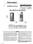
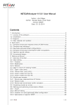
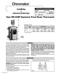
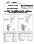
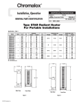
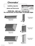
Installation
4
and
WCRT
PK471-4
(Supersedes PK471-3)
OPERATION INSTRUCTIONS
161-562767-001
DECEMBER, 1998
WCRT Weather-Corrosion
Resistant Room
Thermostat
Specifications – Table A
Model
WCRT-100
Temperature Switch
Range (°F) Action
40-100
SPDT
Description
Maximum Rating
120 Vac 240 Vac 277 Vac
Full Load Inductive
16.0A
12.0A
10.0A
Locked Rotor
80.0A
60.0A
55.0A
Non-Inductive
25.0A
25.0A
22.0A
Pilot Duty
125VA
125VA
125VA
UL LISTED
Figure 1
GENERAL
Type WCRT thermostats are intended for use in harsh environments. They tolerate continuous spraying with water, high humidity, airborne contaminates and moderately corrosive conditions.
The nickel plated sensing bulb is attached directly to the bottom of
the case where it is shielded from damage or accumulations of
insulating particles. The molded Noryl case is sealed at the cover
with a neoprene gasket and the adjusting knob opening is closed
with a lubricated O ring. Underwriters Laboratories has tested the
WCRT and found it meets the requirement for NEMA 4X areas.
High levels of accuracy and sensitivity, 21/2° differential, are provided by the WCRT. Switching is done by heavy duty, precision,
single stage, SPDT line voltage snap action switch. Setting is
accomplished by rotating the adjusting knob. The dial face is printed with large, contrasting numbers and letters on a lustrous background for good visibility. Color coding clearly identifies the function of each conductor.
Applications – Automatically controls room temperature by turning electric air heaters on and off. Can be used to control the air
heaters directly, within thermostat rating. For higher ratings use
thermostat with magnetic contactor. Place thermostat on inside wall,
away from undue heating or cooling influences, about 4 feet above
the floor.
© 2010 Chromalox, Inc.
NOTICE: Type WCRT thermostats are designed for temperature
control service only. Because they do not fail safe, they should
not be used for temperature limiting duty.
WARNING: Users should install adequate back-up
controls and safety devices with their electric heating equipment. Where the consequences of failure
may be severe, back-up controls are essential.
Although the safety of the installation is the
responsibility of the user, Chromalox will be
glad to make equipment recommendations.
Principle of Operation – Control action of these thermostats is
provided through the principle of liquid volume change. With a
variation in temperature, the liquid in the sensing element expands
or contracts, causing a bellows to actuate the switching mechanism.
WARNING: Not for use in hazardous environments as
described in National Electrical Code. Failure to comply can result in explosion or fire.
LO Setting is positive open (black to red) for heating loads and
is positive closed (black to blue) for cooling loads.
Note: It is not recommended to switch systems directly from heating to cooling and vice versa.
MOUNTING
Note: Do not mount control where it will be subject to vibration
or shock. Do not mount adjacent to a large magnetic contactor,
as vibration and shock will cause thermostat to interact erratically –
resulting in chattering of the contactor.
1. The proper location of a heavy duty room thermostat is important to assure good performance.
A. Locate where air circulates freely.
B. Never install on or near outside wall.
C. Keep away from windows or doors.
D. Do not locate too close to strong light or other false source
of heat, such as sunlight, steam lines, etc.
E. If electrical conduit leads into cooler or warmer room, plug
up space around wires in the conduit with rock wool.
2. Use sheet metal or wood screws through the four 1/4” diameter
mounting holes in the housing to mount control. (See Figure 2.)
3. WARNING: Any deformations of bulb or capillary
that result in leakage of fluid from control renders control inoperative.
11/2”
1” Dia.
Dimensions
215/16”
35/16”
/4”
3
/4” Dia. (4 Places)
1
57/8”
61/4”
7”
23/4”
23/8”
31/2”
Figure 2
WIRING
WARNING: Hazard of Electrical Shock. Disconnect
all power before wiring or servicing this control.
1. Electric wiring must be installed in accordance with the
National Electrical Code and with local codes by a qualified
person. WARNING: Use copper conductors only.
2. Entrance for wiring is provided by one 1-inch conduit hole in
top of housing. Wiring to control housing should be in moisture-resistant conduit.
3. Remove cover by removing four screws (see Figures 3 and 4).
4. The Chromalox type WCRT thermostat has an enclosed SPDT
switch and may be wired to open on temperature rise (black
to red) or to close on temperature rise (black to blue). (See
Figure 5.)
5. Connect wires according to wiring diagrams (Figures 6 and 7).
Note: Electrical connections should be made with generous loops
of wire – approximately 6” per lead.
6. Replace cover and cover screws. Tighten screws to 4-5 inch
pounds torque.
7. Note: If load amperage or voltage rating exceeds switch rating
and for 3 phase loads, a contactor must be used. Contactor and
wiring to be supplied by customer (see Figure 7).
WARNING: Non-metallic enclosure requires the use
of ground type hub and a jumper wire for grounding the thermostat.
NOTICE: Thermostat is UL Listed for NEMA-4X areas. For it to
retain this listing the sealed conduit hub must also be so listed.
Example Myers Nos. ST-1, ST-2, STR-1, STR-2 or engineering
equivalent.
WIRING
Figure 3
Figure 4
WIRING DIAGRAMS
Control
Voltage
Ground
Red
Black
Blue
Opens On
Temperature Rise
Ground
Common
Closes On
Temperature Rise
Blue
Red
Black
Figure 5
Pilot Light
Line
Contactor
Line
Load
Ground
Blue
Red
Black
Heating Load
Pilot Light
Pilot Light
Heating Load
Line
Load
Pilot Light
Cooling Load
Cooling Load
Single Phase When Load or Voltage Does Not
Exceed Thermostat Rating.
Three Phase and Single Phase When Load Exceeds
Thermostat Rating.
Figure 6
Figure 7
TESTING AND OPERATION
After installation and wiring, to check the operation of heating
systems:
1. Disconnect power.
2. Place the heat/cool selector switch, if applicable, in the heat
position.
3. Adjust the setpoint ten or more degrees below the temperature
of the controlled space.
4. Restore power.
5. Slowly adjust the setpoint upward. When the setpoint reaches
the approximate temperature of the controlled space, the heating equipment should start.
To check the operation of the cooling systems:
1. Disconnect power.
2. Place the heat/cool selector switch, if applicable, in the cool
position.
3. Adjust the setpoint ten or more degrees above the temperature
of the controlled space.
4. Restore power.
5. Slowly adjust the setpoint downward. When the setpoint
approximates the temperature of the controlled space, the cooling equipment should start.
Limited Warranty:
Please refer to the Chromalox limited warranty applicable to this product at
http://www.chromalox.com/customer-service/policies/termsofsale.aspx.
1347 HEIL QUAKER BLVD., LAVERGNE, TN 37086
Phone: (615) 793-3900
www.chromalox.com