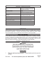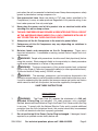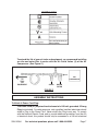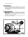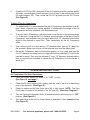
1
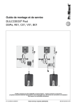
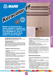
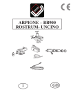
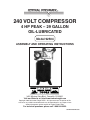
240 VOLT COMPRESSOR
4 HP PEAK – 29 GALLON
Oil-lubricated
Model 92504
ASSEMBLY AND OPERATING INSTRUCTIONS
3491 Mission Oaks Blvd., Camarillo, CA 93011
Visit our Web site at: http://www.harborfreight.com
Copyright© 2005 by Harbor Freight Tools®. All rights reserved. No portion of this
manual or any artwork contained herein may be reproduced in any shape or form
without the express written consent of Harbor Freight Tools.
For technical questions, please call 1-800-444-3353.
COVER REVISED 02/06
PRODUCT SPECIFICATIONS
Motor
240 V~ / 60 Hz / Single Phase / 4 HP Peak /
3 HP Working / 3,400 RPM / 9 Load Amps /
Two Capacitor (Run & Start)
Overload Reset Button
15 Amp
Power Cord
12 Gauge, 3-Wire (Stripped), 20 Ft. Long
240 Volt Power Cord Plug Not Included.
Air Tank Capacity
29 Gallons
CFM Airflow
16.4 @ 40 PSI / 15.7 @ 70 PSI /
14.5 @ 90 PSI / 13.0 @ 115 PSI
Compressor Pump Type
Dual V-Head Cylinder / Belt Driven
Safety Valve Setting
120 PSI
Air Pressure Gauge Indicators
0-200 PSI in 5 PSI Increments
Automatic Shut Off Capability
Shut Off at 115 PSI / Starts at 80 PSI
Required Air Quick Connectors (Not Included)
Qty. 2 / 1/4”-18 NPT Quick Connectors
V-Belt Size
A1118 Li
Base Mounting Holes
Qty. 4 @ 1/2” Diameter
Weight
205 Pounds
UNPACKING
When unpacking, check to make sure all the parts shown on the Parts List at the end of
the manual are included. If any parts are missing or broken, please call Harbor Freight
Tools at the number shown on the cover of this manual as soon as possible.
SAVE THIS MANUAL
You will need this manual for the safety warnings and precautions, assembly, operating,
inspection, maintenance and cleaning procedures, parts list and assembly diagram. Keep
your invoice with this manual. Write the invoice number on the inside of the front cover.
Keep this manual and invoice in a safe and dry place for future reference.
GENERAL SAFETY RULES
WARNING!
READ AND UNDERSTAND ALL INSTRUCTIONS
Failure to follow all instructions listed below may
result in electric shock, fire, and/or serious injury.
SAVE THESE INSTRUCTIONS
WORK AREA
1.
Keep your work area clean and well lit. Cluttered benches and dark areas invite
accidents.
REV 02/06
SKU 92504
For technical questions, please call 1-800-444-3353.
Page 2
2.
Do not operate compressors in explosive atmospheres, such as in the presence
of flammable liquids, gases, or dust. Compressors create sparks which may
ignite the dust or fumes.
3.
Keep bystanders, children, and visitors away while operating a compressor.
Provide barriers or shields as needed.
ELECTRICAL SAFETY
1.
Grounded compressors must be plugged into an outlet properly installed
and grounded in accordance with all codes and ordinances. Never remove
the grounding prong or modify the plug in any way. Do not use any adapter
plugs. Check with a qualified electrician if you are in doubt as to whether the
outlet is properly grounded. If the compressors should electrically malfunction
or break down, grounding provides a low resistance path to carry electricity away
from the user.
2.
Do not expose compressors to rain or wet conditions. Water entering an electric
motor will increase the risk of electric shock.
3.
Do not abuse the Power Cord. Never use the Power Cord to pull the Plug from
an outlet. Keep the Power Cord away from heat, oil, sharp edges, or moving
parts. Replace damaged Power Cords immediately. Damaged Power Cords
increase the risk of electric shock.
4.
An extension cord must never be used with this item. Connecting
this item to an outlet through an extension cord may cause electrical
damage to the motor and could present a fire hazard.
PERSONAL SAFETY
1.
Stay alert. Watch what you are doing, and use common sense during use. Do
not use while tired or under the influence of drugs, alcohol, or medication. A
moment of inattention while operating may result in serious personal injury.
2.
Dress properly. Do not wear loose clothing or jewelry. Contain long hair.
Keep your hair, clothing, and gloves away from moving parts. Loose clothes,
jewelry, or long hair can be caught in moving parts.
3.
Avoid accidental starting. Be sure the Power Switch is turned off before plugging
in. Plugging in compressors with the Power Switch on, invites accidents.
4.
Remove adjusting keys or wrenches before turning the compressor on. A
wrench or a key that is left attached to a rotating part of the compressor may result
in personal injury.
5.
Do not overreach. Keep proper footing and balance at all times.
SKU 92504
For technical questions, please call 1-800-444-3353.
Page 3
6.
Use safety equipment. Always wear eye protection. Make sure you are wearing
your protective clothing, safety glasses with side shields and dust mask or air
respirator, if appropriate.
TOOL USE AND CARE
1.
Do not force the compressor. Use the correct compressor for your application.
The correct compressor will do the job better and safer at the rate for which it is
designed. Never attempt to force the compressor to provide more pressure than it
was designed for.
2.
Do not use the compressor if the Power Switch does not turn it on or turn it
off. Any compressor that cannot be controlled with the Power Switch is dangerous
and must be repaired or replaced.
3.
Disconnect the Power Cord Plug from the power source before making any
adjustments, changing accessories, or storing the compressor. Such preventive
safety measures reduce the risk of starting the compressor accidentally.
4.
Keep idle compressors out of reach of children and other untrained persons.
Compressors are dangerous in the hands of untrained users.
5.
Maintain compressors with care. Keep all components of this product clean
and dry. Do not use a damaged compressor. Tag damaged compressors “Do not
use” until repaired.
6.
Check for misalignment or binding of moving parts, breakage of parts, and
any other condition that may affect the compressor’s operation. If damaged,
have the compressor serviced before using. Many accidents are caused by
poorly maintained compressors.
7.
Use only accessories that are recommended by the manufacturer for your
model. Accessories that may be suitable for one compressor may become
hazardous when used on another compressor.
SERVICE
1.
Compressor service must be performed only by qualified repair personnel.
Service or maintenance performed by unqualified personnel could result in a risk
of injury.
2.
When servicing a compressor, use only identical replacement parts. Follow
instructions in the “Inspection, Maintenance, And Cleaning” section of this
manual. Use of unauthorized parts or failure to follow maintenance instructions
may create a risk of electric shock or injury.
SKU 92504
For technical questions, please call 1-800-444-3353.
Page 4
SPECIFIC SAFETY RULES
1.
CAUTION! Prior to its first use, and thereafter prior to each subsequent use,
make sure to fill the Air Compressor with a premium quality, 30 weight, nondetergent oil to the specified level. Running the Air Compressor with no oil or
with low oil will cause damage to the equipment and void its warranty. Refer to the
“Operating Instructions” section for details on filling the Air Compressor with oil.
2.
When filling the Air Compressor with oil, make sure to unscrew (do not pull)
the Oil Fill Cap to remove.
3.
Use eye and ear protection. Always wear ANSI-approved safety impact eye
goggles, and ear plugs when using the Air Compressor.
4.
Make sure all tools and equipment used with the Air Compressor are rated to
the appropriate air pressure capacity of the Air Compressor. Do not use any
tool or equipment that does not operate from 0-115 PSI. If necessary, check the
owner’s manual of the tool or equipment for its air pressure rating.
5.
Always disconnect the Air Compressor from its electrical outlet, release any
remaining air pressure from the unit, and disconnect all pneumatic tools and
equipment from the unit, before performing any services or maintenance.
6.
Avoid injury. Never direct the air jet at people or animals.
7.
Inspect safety valve daily. If the safety valve is not working properly, tank pressure
can build up to dangerous levels. The tank could explode. For this reason, pull the
ring on the safety valve before each use and verify that it operates freely. Replace
safety valve if it does not operate freely.
Never remove or alter the factory sealed Safety Release Valve.
8.
Do not attempt to readjust the automatic start and shutoff valves. Any change
to the automatic ON/OFF pressure levels will cause additional stress on the motor,
which may result in shortened motor life.
9.
Drain the Air Compressor’s air tank every day. Do not allow moisture to build
up inside the Air Tank.
10.
Do not unscrew the tank drain valve so that more than four threads are
showing.
11.
Avoid risk of tank explosion.
a) Avoid weakening of tank by draining condensation after each use.
b) Never modify tank by drilling holes, welding to it, or modifying it’s parts.
c) The tank is designed, and factory set, to operate within a specific pressure
range. For that reason, never make adjustments to, or substitute parts, to the
compressor.
12.
Avoid bodily injury from moving parts. The compressor cycles on automatically,
without notice. For this reason, always keep hands and arms away from compressor
SKU 92504
For technical questions, please call 1-800-444-3353.
Page 5
parts when the unit is connected to electrical power. Always have compressor safety
guards in place before turning compressor on.
13.
Use approved air hose. Never use plastic or PVC pipe (unless specified for Air
Compressors) to carry air under pressure. Regardless of its pressure rating, it can
burst under pressure. Use only metal pipe.
14.
Never plug the power cord of this product into an electrical outlet while
standing on a wet or damp surface.
15.
This Air Compressor may require a dedicated electrical circuit
as the amperage draw under full load, combined with use of
any other item, may overload your circuit.
16.
Always turn off the Air Compressor in the event of a power failure.
17.
Performance of this Air Compressor may vary depending on variations in
local line voltage.
18.
Maintain labels and nameplates on the Air Compressor. These carry
important information. If unreadable or missing, contact Harbor Freight Tools for a
replacement.
19.
WARNING! People with pacemakers should consult their physician(s) before
using this product. Electromagnetic fields in close proximity to a heart pacemaker
could cause interference to or failure of the pacemaker.
20.
WARNING! The brass components of this product contain lead, a chemical
known to the State of California to cause birth defects (or other reproductive harm).
(California Health & Safety code § 25249.5, et seq.)
21.
WARNING! The warnings, precautions, and instructions discussed in this
instruction manual cannot cover all possible conditions and situations that may occur.
It must be understood by the operator that common sense and caution are factors
which cannot be built into this product, but must be supplied by the operator.
SAVE THESE INSTRUCTIONS
GROUNDING
1.
WARNING!
The Power Cord (31) requires the attachment of a 240 volt,
grounded, 3-Prong Plug (not included). For safety purposes, only a qualified,
certified, electrician should attach a Plug to the Power Cord. Never modify the Plug
in any way. To comply with the National Electric Code, and to provide additional
protection from the risk of electrical shock, this product should only be connected
to a 240 volt electrical outlet that is properly grounded.
2.
Do not use the tool if the Power Cord or Plug is damaged. If damaged, have it
repaired by a qualified service facility before use.
SKU 92504
For technical questions, please call 1-800-444-3353.
Page 6
SYMBOLOGY
To extend the life of your air tools and equipment, we recommend installing
an oiler and water filter in series with the Air Outlet Valves (4) of the Air
Compressor. (See Figure C.)
AIR
COMPRESSOR
TO
TOOL
OR
EQUIPMENT
OILER
WATER
FILTER
FIGURE C
ASSEMBLY INSTRUCTIONS
To Attach A Power Cord Plug:
The Power Cord (31) requires the attachment of a 240 volt, grounded, 3-Prong
Plug (not included). For safety purposes, only a qualified, certified, electrician should
attach a Plug to the Power Cord. Never modify the Plug in any way. To comply
with the National Electric Code, and to provide additional protection from the risk
of electrical shock, this product should only be connected to a 240 volt electrical
SKU 92504
For technical questions, please call 1-800-444-3353.
Page 7
outlet that is properly grounded.
To Attach Quick Connectors:
Prior to use, the Air Compressor requires the attachment of a 1/4” NPT Quick
Connector (not included) to each of its two Air Outlet Valves (4). To do so, wrap
approximately 4” of pipe thread sealant tape (not included) around the male threads
of the Quick Connectors. Then, firmly screw the Quick Connectors into the Air Outlet
Valves. (See Figure D.)
To Fill The Air Compressor With Oil:
1.
CAUTION! Prior to its first use, and thereafter prior to each subsequent
use, make sure to fill the Air Compressor with a premium quality, 30 weight,
non-detergent oil. Running the Air Compressor with no oil or low oil will cause
damage to the equipment and void its warranty.
2.
When filling the Air Compressor with oil, make sure to unscrew (do not pull) the Oil
Fill Cap (28) to remove. (See Figure D.)
OIL FILL CAP
(28)
OIL LEVEL
INDICATOR
(35)
AIR
OUTLET VALVE
(4)
SKU 92504
AIR
OUTLET VALVE
(4)
For technical questions, please call 1-800-444-3353.
FIGURE D
Page 8
3.
Once the Oil Fill Cap (28) is removed, fill the Air Compressor with a premium quality,
30 weight, non-detergent oil until the level of the oil rises to the midway point in the
Oil Level Indicator (35). Then, screw the Oil Fill Cap back onto the Oil Fill Hole.
(See Figure D.)
To Mount The Air Compressor:
1.
For added safety, it is recommended that the Air Compressor be mounted on a flat,
level, sturdy, concrete floor surface capable of withstanding the weight of the Air
Compressor and any additional tools and accessories.
2.
To mount the Air Compressor, with assistance, move the unit to the location where
it is to be used. Using the four 1/2” diameter mounting holes on the feet of the Air
Compressor as a template, mark the spots where four 1/2” diameter holes will be
drilled in the concrete or wood floor. Then, temporarily set the Air Compressor
aside.
3.
Use a masonry drill bit to drill the four 1/2” diameter holes (about 3”-4” deep) into
the concrete. Make sure to blow out the concrete dust from the drilled holes.
4.
Set the Air Compressor back to the location where it is to be used, and align the
four 1/2” diameter mounting holes in its legs with the four predrilled 1/2” holes in the
concrete or wood. Then use four minimum 3” long, 1/2” diameter, concrete anchor
bolts or lag bolts (not included) to secure the Air Compressor to the concrete or
wood floor.
OPERATING INSTRUCTIONS
Air Compressor Pre-Start Procedures:
1.
Press the Power Switch (9) down to its “OFF” position.
(See Figure E, next page.)
2.
Check the Oil Level Indicator (35), making sure the level of the oil is at the midway
point in the Indicator. (See Figure E.)
3.
Check to make sure the Tank Drain Valve (33) is fully closed. NOTE: The Tank
Drain Valve is located at the bottom of the Air Tank (32). (See Assy. Diagram.)
4.
Turn the Pressure Adjustment Knob (6) counterclockwise all the way to its “OFF”
position. (See Figure E.)
5.
Turn each Lever on the two Air Outlet Valves (4) backward to their closed position.
(See Figure E.)
SKU 92504
For technical questions, please call 1-800-444-3353.
Page 9
6.
If using only one of the two Air Outlet Valves (4), attach an air hose (not included)
to the Air Outlet Valve. Then, attach the other end of the air hose to the pneumatic
tool that will be used. If using both Air Outlet Valves simultaneously, attach an air
hose to each Air Outlet Valve. Then, attach the other ends of the air hoses to their
respective pneumatic tools. (See Figure E.)
To Start The Air Compressor:
1.
Plug the Power Cord Plug (31) into the nearest 220 volt, grounded, electrical
outlet.
2.
Pull up on the Power Switch (9) to its “ON” position. (See Figure E.)
3.
Turn the Pressure Adjustment Knob (6) clockwise about halfway to its “ON” position.
(See Figure E.)
4.
If using only one Air Outlet Valve (4), allow sufficient time for its Pressure Gauge
(5) to indicate at least 80 PSI. If using both Air Outlet Valves, allow sufficient time
for both Pressure Gauges (5) to indicate at least 80 PSI.
(See Figure E.)
OVERLOAD
RESET
BUTTON
(42)
POWER SWITCH
(9)
PRESSURE
GAUGE
(5)
AIR
OUTLET
VALVE
LEVER
AIR
OUTLET
VALVE
(4)
FIGURE E
SKU 92504
AIR OUTLET
VALVE
LEVER
OIL LEVEL
INDICATOR
(35)
0
SAFETY RELEASE
VALVE (3)
AIR OUTLET
VALVE
(4)
PRESSURE
ADJUSTMENT KNOB
(6)
For technical questions, please call 1-800-444-3353.
Page 10
5.
Check to make sure the pneumatic tools that will be used are turned off and properly
connected to their air hoses.
6.
Once the Pressure Gauge (5) has reached at least 80 PSI, turn the Lever on the Air
Outlet Valve (4) forward to its open position in order to supply air to the pneumatic
tool. If both Air Outlet Valves are being used, turn both Levers forward to their open
positions. (See Figure E.)
7.
IMPORTANT: Both Pressure Gauges (5) should always indicate the same PSI
reading, meaning that if two pneumatic tools are being hooked up to the Air
Compressor both pneumatic tools should operate on the same PSI rating.
8.
If necessary, turn the Pressure Adjustment Knob (6) clockwise to increase air
pressure to the pneumatic tool(s) or counterclockwise to decrease air pressure to
the pneumatic tool(s). (See Figure E.)
To Use The Air Tank Safety Release Valve:
1.
The Safety Release Valve (3) is used when decompression is needed quickly and
efficiently. (See Figure E.)
2.
To decompress the Air Tank (32) pressure, press down on the Power Switch (9) to
turn off the Air Compressor. (See Figure E.)
3.
Pull out on the Safety Release Valve Ring (3) to immediately release air pressure
in the Air Tank (32). (See Figure E.)
To Use The Overload Reset Button:
1.
The Air Compressor is equipped with an internal electrical circuit breaker which is
designed to automatically shut off the Air Compressor in the event its Motor (14)
becomes overheated or in the event of an electrical power outage.
(See Figure E.)
2.
Should the Air Compressor automatically shut off, press the Power Switch (9) down
to its “OFF” position. (See Figure E.)
3.
Wait several minutes to allow the Air Compressor’s Motor (14) to cool (if due to
electrical power outage, wait until power is resumed).
4.
Press the Overload Reset Button (42) to reset the electrical circuit breaker. If it does
not reset, wait a few additional minutes and try again. Then, pull up on the Power
Switch (9) to its “ON” position to resume work. (See Figure E.)
SKU 92504
For technical questions, please call 1-800-444-3353.
Page 11
To Turn Off The Air Compressor:
1.
When finished using the Air Compressor, press down on its Power Switch (9) to
turn off the unit.
(See Figure E.)
2.
Disconnect the Power Cord Plug (31) from its electrical outlet.
3.
Turn on the pneumatic tools to expend all remaining compressed air from the Air
Compressor, air hoses, and pneumatic tools.
4.
Turn the Pressure Adjustment Knob (6) counterclockwise all the way to its “OFF”
position. (See Figure E.)
5.
Turn each Lever on the two Air Outlet Valves (4) backward to their closed position.
(See Figure E.)
6.
Disconnect the air hoses from the Air Outlet Valves (4). (See Figure E.)
7.
Disconnect the air hoses from the pneumatic tools. Then, keep the air hoses and
pneumatic tools in a clean, dry location out of reach of children.
INSPECTION, MAINTENANCE, AND CLEANING
1.
WARNING! Always make sure the Power Switch (9) is in its “OFF” position,
the Air Compressor is disconnected from its electrical outlet, and all remaining
compressed air is expelled from the system before performing any inspection,
maintenance, or cleaning.
2.
Before each use: Inspect the general condition of the Air Compressor. Check for
misalignment or binding of moving parts, cracked or broken parts, loose or damaged
connections, and any other condition that may affect its safe operation. If abnormal
noise or vibration occurs, have the problem corrected before further use. Do not
use damaged equipment.
3.
Before each use: Make sure to fill the Air Compressor with a premium quality,
30 weight, non-detergent oil. Running the Air Compressor with no oil or low oil
will cause damage to the equipment and void its warranty. When filling the Air
Compressor with oil, make sure to unscrew (do not pull) the Oil Fill Cap (28) to
remove. Fill with oil until the level of the oil rises to the midway point in the Oil Level
Indicator (35). Then, screw the Oil Fill Cap back onto the Oil Fill Hole.
(See Figure F, next page.)
SKU 92504
For technical questions, please call 1-800-444-3353.
Page 12
4.
NOTE: Each time the Oil Fill Cap (28) is removed, observe the PCV Filter (41) that
is located inside the Oil Fill Cap. When necessary, remove the PCV Filter and clean
with a mild solvent. Allow the PCV Filter to dry. Then, replace the PCV Filter in the
Oil Fill Cap, and screw the Oil Fill Cap back onto the oil fill hole. (See Figure F.)
PCV FILTER
(41)
OIL FILL HOLE
OIL FILL CAP
(28)
FIGURE F
5.
Weekly: The Air Compressor is equipped with two Air Filters (38) which should be
cleaned or replaced on a weekly basis. To clean or replace the Air Filters, unscrew
and remove the Wing Nut (36) on the Air Filter Cap (37). Remove the Air Filter
Cap, Air Filter, and Air Filter Bowl (39). Clean the Air Filter with compressed air or,
if necessary, replace the old Air Filter with a new Air Filter. Clean the Air Filter Cap
and Air Filter Bowl with a mild solvent and then dry. Then, replace the Air Filter Bowl,
Air Filter, Air Filter Cap, and Wing Nut. Repeat these procedures for the remaining
Air Filter. (See Figure G.)
WING NUT
(36)
AIR FILTER
(38)
WING NUT
(36)
AIR FILTER BOWL
(39)
AIR FILTER CAP
(37)
FIGURE G
SKU 92504
For technical questions, please call 1-800-444-3353.
Page 13
6.
To replace the V-Belt: The Air Compressor is equipped with a V-Belt (size: A1168
Li). To replace the V-Belt, remove the four Nuts (24) and four Flat Washers (23) on
the Outer Guard Screen (25). Next, remove the three Clips (34) located at the top
of the Outer Guard Screen. Then, remove the Outer Guard Screen.
(See Figure H.)
CLIP
(34)
CLIP
(34)
OUTER GUARD
SCREEN
(25)
LARGE
V-BELT
MOTOR
BELT WHEEL
(27) PULLEY (14)
NUT (24)
FLAT WASHER (23)
NUT (24)
FLAT WASHER (23)
7.
CLIP
(34)
FIGURE H
Loosen the four Screws (30) that hold the Motor (14) in place. Then, slide the Motor
toward the Large Belt Wheel to loosen the tension on the V-Belt (27).
(See Figures H and I.)
SIDE VIEW
END VIEW
SCREW
(30)
SCREW
(30)
SCREW
(30)
FIGURE I
SKU 92504
For technical questions, please call 1-800-444-3353.
Page 14
8.
Remove the loose V-Belt (27) from the Large Belt Wheel and Motor Pulley (14).
(See Figure H.)
9.
Install a new V-Belt (27) on the Large Belt Wheel and Motor Pulley (14).
(See Figure H.)
10.
Slide the Motor (14) back toward its original position to tighten the tension on the
V-Belt (27). NOTE: To determine the proper tension on the V-Belt, with your index
finger press down on the V-Belt. The V-Belt should deflect downward about 3/4”.
If necessary move the Motor Pulley (14) toward or away from the Large Belt Wheel
until the V-Belt deflects downward 3/4”. Then, retighten the four Screws (3) to secure
the Motor (14) in place. (See Figures I and J.)
3/4”
LARGE
BELT WHEEL
FIGURE J
V-BELT
(27)
MOTOR PULLEY
(14)
11.
To clean, use a shop vacuum cleaner, or use compressed air.
12.
When storing, make sure to keep the Air Compressor in a safe, clean, and dry
location out of reach of children.
13.
CAUTION! All maintenance, service, or repairs not listed in this manual are only to be attempted by a qualified service technician.
PLEASE READ THE FOLLOWING CAREFULLY
THE MANUFACTURER AND/OR DISTRIBUTOR HAS PROVIDED THE PARTS LIST AND ASSEMBLY
DIAGRAM IN THIS MANUAL AS A REFERENCE TOOL ONLY. NEITHER THE MANUFACTURER OR
DISTRIBUTOR MAKES ANY REPRESENTATION OR WARRANTY OF ANY KIND TO THE BUYER THAT
HE OR SHE IS QUALIFIED TO MAKE ANY REPAIRS TO THE PRODUCT, OR THAT HE OR SHE IS
QUALIFIED TO REPLACE ANY PARTS OF THE PRODUCT. IN FACT, THE MANUFACTURER AND/OR
DISTRIBUTOR EXPRESSLY STATES THAT ALL REPAIRS AND PARTS REPLACEMENTS SHOULD BE
UNDERTAKEN BY CERTIFIED AND LICENSED TECHNICIANS, AND NOT BY THE BUYER. THE BUYER
ASSUMES ALL RISK AND LIABILITY ARISING OUT OF HIS OR HER REPAIRS TO THE ORIGINAL
PRODUCT OR REPLACEMENT PARTS THERETO, OR ARISING OUT OF HIS OR HER INSTALLATION
OF REPLACEMENT PARTS THERETO.
SKU 92504
For technical questions, please call 1-800-444-3353.
Page 15
PARTS LIST
Part
1
2
3
4
5
6
7
8
9
10
11
12
13
14
15
16
17
18
19
20
21
Description
Flat Washer (8)
Screw (M8x16)
Safety Release Valve
Air Outlet Valve
Pressure Gauge
Pressure Adjustment Knob
Connector
Top Cover
Power Switch
Screw (M8x25)
Spring Washer (8)
Flat Washer (8)
Nut (M8)
Motor
Tube
Cap
Ring
Connector
No Return Valve
Exhaust
Bracket
Qty.
Part
4
4
1
2
2
1
2
1
1
4
8
8
8
1
1
1
1
1
1
1
1
22
23
24
25
26
27
28
29
30
31
32
33
34
35
36
37
38
39
40
41
42
Description
Screw (M5x16)
Flat Washer (5)
Nut (M5)
Outer Guard Screen
Inner Guard Screen
V-Belt (A1168 Li)
Oil Fill Cap
Head Assembly
Screw (M8x16)
Power Cord
Air Tank
Tank Drain Valve
Clip
Oil Level Indicator
Wing Nut
Air Filter Cap
Air Filter
Air Filter Bowl
Oil Drain Plug
PCV Filter
Overload Reset Button
Qty.
5
5
5
1
1
1
1
1
1
1
1
1
3
1
2
2
2
2
1
1
1
NOTE:
Some parts are listed and shown for illustration purposes only,
and are not available individually as replacement parts.
SKU 92504
For technical questions, please call 1-800-444-3353.
Page 16
ASSEMBLY DIAGRAM
34
23/24
25
20
19
17
18
16
15
26
27
21/22/23/24
9
28/41
5
8
14
7
10/11/12/13
6
4
3
29
30
11/12/13
2
1
35
36/37/38/39
40
31
32
33
NOTE:
Some parts are listed and shown for illustration purposes only,
and are not available individually as replacement parts.
SKU 92504
For technical questions, please call 1-800-444-3353.
Page 17
WIRING DIAGRAM
REV 05/06
SKU 92504
For technical questions, please call 1-800-444-3353.
Page 18