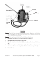
1
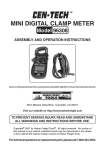
AIR/OVER HYDRAULIC 20 TON
JACK
Model 96147
ASSEMBLY AND OPERATING INSTRUCTIONS
Due to continuing improvements, actual product may differ slightly from the product described herein.
®
3491 Mission Oaks Blvd., Camarillo, CA 93011
Visit our Web site at http://www.harborfreight.com
To prevent serious injury, read and understand
all warnings and instructions before use.
Copyright © 2007 by Harbor Freight Tools. All rights reserved. No portion of this manual or
any artwork contained herein may be reproduced in any shape or form without the express
written consent of Harbor Freight Tools.
For technical questions and replacement parts, please call 1-800-444-3353
Specifications
Capacity
20 Ton Maximum
Height
10-3/8” Minimum
20-1/4” Maximum (with screw extended)
Ram
2.12” Diameter x 6-1/2” travel
Air Inlet Fitting
1/4” NPT
Weight
37 Pounds
Base Dimensions
9-7/8” L x 6-1/2” W
Air Hose
3/8” x 46-1/8” L with crimped hose fittings
Air Pressure
70 - 150 PSI
Save This Manual
You will need the manual for the safety warnings and precautions, assembly instructions,
operating and maintenance procedures, parts list and diagram. Keep your invoice with this
manual. Write the invoice number on the inside of the front cover. Keep the manual and
invoice in a safe and dry place for future reference.
Safety Warnings and Precautions
WARNING: When using tool, basic safety precautions should always be followed to reduce
the risk of personal injury and damage to equipment.
Read all instructions before using this tool.
1.
Do not overload this equipment. Know the weight of the item being lifted.
2.
Use Jack for lifting only. Do not use this equipment for any other purpose. Immediately after lifting, support the load with appropriate supporting equipment.
3.
Place Jack correctly. Only use this equipment on a surface that is stable, level, clean
and dry, and capable of sustaining the load.
4.
Stabilize load. Ensure that the load remains stable at all times. Do not attempt to shift
a load while it is on the Jack.
5.
When lifting a vehicle, apply the emergency brake, and block all wheels.
6.
Do not work under a load while it is being supported by the Jack.
7.
Keep work area clean. Cluttered areas invite injuries.
8.
Observe work area conditions. Do not use machines or power tools in damp or wet
locations. Do not expose to rain. Keep work area well lit.
9.
Keep children away. Children must never be allowed in the work area. Do not let
them handle machines or tools.
10.
Store idle equipment. When not in use, tools must be stored in a dry location to inhibit
rust. Always lock up tools and keep out of reach of children.
REV 07i
SKU 96147
For technical questions, please call 1-800-444-3353.
Page 11.
Use the right tool for the job. Do not attempt to force a small tool or attachment to
do the work of a larger industrial tool. Do not use a tool for a purpose for which it was
not intended.
12.
Dress properly. Do not wear loose clothing or jewelry as they can be caught in moving parts. Protective, electrically non-conductive clothes and non-skid footwear are
recommended when working. Wear restrictive hair covering to contain long hair.
13.
Use eye and ear protection. Always wear ANSI approved impact safety goggles.
Wear an ANSI approved dust mask or respirator when working around metal, wood,
and chemical dusts and mists.
14.
Do not overreach. Keep proper footing and balance at all times. Do not reach over
or across running machines.
15.
Maintain tools with care. Keep tool clean for better and safer performance. Follow
instructions for lubricating and changing accessories. The handles must be kept clean,
dry, and free from oil and grease at all times.
16.
Remove adjusting keys and wrenches. Check that keys and adjusting wrenches are
removed from the tool or machine work surface before plugging it in.
17.
Be alert. Watch what you are doing and use common sense when operating a power
tool. Do not use a power tool while tired or under the influence of drugs, alcohol, or
medication. A moment of inattention while operating power tools can result in serious
personal injury.
18.
Check for damaged parts. Check for alignment and binding of moving parts; any
broken parts or mounting fixtures; and any other condition that may affect proper operation. Any part that is damaged should be properly repaired or replaced by a qualified
technician.
19.
Replacement parts and accessories. When servicing, use only identical replacement
parts. Use of any other parts will void the warranty.
20.
Not to be used for any aircraft purposes.
Warning: The warnings, cautions, and instructions discussed in this instruction manual cannot cover all possible conditions and situations that
may occur. It must be understood by the operator that common sense
and caution are factors which cannot be built into this product, but must
be supplied by the operator.
Unpacking
When unpacking, check to make sure the all parts are included. If any parts are missing or
broken, please call Harbor Freight Tools at the number on the cover of this manual as soon
as possible.
SKU 96147
For technical questions, please call 1-800-444-3353.
Page Assembly
1.
Screw the Pump Elbow (3) into the Air Pump (4) and tighten.
2.
Connect the Air Hose (2) to the Pump Elbow (3).
3.
Connect the other end of the Air Hose to the Air Valve Body (1.6)
4.
Connect the two pipe Handles (5, 6) together.
5.
Check level of hydraulic oil, fill if necessary (See “Oil Replacement” section of manual
for directions).
Operation
Lifting
1.
Test Jack to ensure proper working condition before use, raise and lower ram to see if
operation is smooth and without hitch.
2.
Place the slotted end of the Lower Handle (6) over the Release Valve Screw (18). Turn
the Valve Release screw clockwise until snug. (See FIGURE A)
3.
Place the Jack into position under the load.
4.
Check manufacturer’s manual of vehicle or other item being lifted to find the recommended lifting points.
5.
Adjust the Extension Screw (44) as needed, turn counterclockwise to raise, clockwise
to lower.
6.
Insert the large end of the Handle assembly into the Handle Sleeve (7).
7.
Connect the air supply hose lock fitting into the Hose Connector (1.1).
8.
The Lever (1.13) should be Off (not in the locked position).
9.
Press the Lever (1.13) to the On position and lock using the Lock Lever (1.17).
10.
Raise the Jack by alternately lifting and lowering the Handle assembly or by depressing Lever (1.13).
SKU 96147
For technical questions, please call 1-800-444-3353.
Page Extension
Screw (44)
FIGURE A
Air Pump (4)
Handle (5,6) in
Handle Sleeve (7)
Pump
Elbow (3)
Lever (1.13) and
Lock Lever (1.17)
Release
Valve (18)
Hose Connector
(1.1)
Air Hose (2)
Hose Band
(1.16)
Lowering
Caution: Clear tools from underneath the load before lowering. Keep hands and feet clear.
Before lowering the Jack, the operator must ensure that all bystanders are free and
clear of the load before continuing.
Caution: Avoid rapid descent of the load. Turn the Release Valve slowly.
1.
Release the Lock Lever (1.17) to stop air flow to the Air Motor (4).
2.
Remove air supply hose from the Air Inlet Fitting.
3.
Place the slotted end of the Handle (5, 6) assembly over the Release Valve Screw
(18).
4.
Slowly and carefully lower the load by turning the Release Valve counterclockwise in
extremely small increments using only the Handle assembly (never your hand).
5.
Remove the Jack.
SKU 96147
For technical questions, please call 1-800-444-3353.
Page Maintenance
General Care
1.
Periodically lubricate the joints and Extension Screw (44) with a light oil as needed.
2.
Clean the outside of the Jack with a dry, clean cloth.
3.
If the Jack is exposed to moisture, wipe dry with a clean cloth and lubricate as noted
above.
4.
Store jack with Extension Screw (44) and Ram (48) fully collapsed.
Purging Air from the Hydraulic System
Air bubbles can become trapped inside the hydraulic system thereby reducing the efficiency
of the Jack. Purge the air from the system if lift efficiency drops.
1.
Place the slotted end of the Handle (5, 6) assembly over the Valve Release (18) and
turn 1-1/2 turns counterclockwise.
2.
Remove the oil Filler Plug (23) on the side of the jack Reservoir (37) by gently pulling
and turning it.
3.
Rapidly pump the Handle assembly several times to purge the air from the hydraulic
system.
4.
Turn the Release Valve screw clockwise until snug using the Handle assembly.
5.
Top off jack Reservoir (37) as described below.
6.
Replace the Filler Plug (23).
Oil Replacement
1.
Place Jack in an upright position.
2.
Completely lower the Ram (48).
3.
Remove the Filler Plug (23).
4.
Fill with high-quality hydraulic jack oil to the lower rim of the fill hole.
5.
Purge air from the hydraulic system as previously described.
6.
Top off with more hydraulic oil.
7.
Replace Filler Plug (23).
SKU 96147
For technical questions, please call 1-800-444-3353.
Page Parts List
Part
Description
Qty
Part
Description
Qty
1.1
Hose Connector
1
18
Release Valve
1
1.2
Connecting Nut
1
19
Release Valve Seal
1
1.3
Air Filter
1
20
Steel Ball 6.35
1
1.4
O-Ring 18 X 2.4
1
21
Pin
1
1.5
Connector
1
22
Valve Spring
2
1.6
Valve Body
1
23
Filler Plug
1
1.7
Spring
1
24
Screw
2
1.8
Packing
1
25
Plug Screw
1
1.9
Throttle
1
26
Plunge Washer
1
1.10
O-Ring 3 x 1.6
1
27
Overload Valve Screw
1
1.11
O-Ring 18 x 2.4
1
28
Safety Valve Spring
1
1.12
Nut
1
29
Overload Tapering Valve
1
1.13
Lever
1
30
Filter Net
2
1.14
Lever Ring
1
31
Spring Washer 8
2
1.15
Air Valve
1
32
Nut 8
2
1.16
Hose Connector
2
33
Bolt M8 x 35
2
1.17
Lock Lever
1
34
Base
1
2
Air Hose
1
35
Plug Screw
4
3
Pump Elbow
1
36
Cylinder Bottom Seal
1
4
Air Pump
1
37
Reservoir
1
5
Handle Upper
1
38
Packing
1
6
Handle Lower
1
39
Cylinder
1
7
Handle Sleeve
1
40
Steel Ball Retainer
2
8
Shaft Pin
3
41
Cylinder Top Seal
1
9
Cotter Pin
3
42
O-Ring
1
10
Pump Plunger
1
43
Top Nut
1
11
Pump Plunger Retainer
1
44
Extension Screw
1
12
O-Ring
1
45
O-Ring
1
13
Dust Proof Ring
1
46
O-Ring Retainer
1
14
Pump Reservoir
1
47
Ram Header
1
15
Copper Washer
1
48
Ram
1
16
Steel Ball 6
6
49
Spring
2
17
Plunger Connecting Rod
1
50
Spring Plate
1
PLEASE READ THE FOLLOWING CAREFULLY
THE MANUFACTURER AND/OR DISTRIBUTOR HAS PROVIDED THE PARTS DIAGRAM IN THIS
MANUAL AS A REFERENCE TOOL ONLY. NEITHER THE MANUFACTURER NOR DISTRIBUTOR MAKES ANY
REPRESENTATION OR WARRANTY OF ANY KIND TO THE BUYER THAT HE OR SHE IS QUALIFIED TO MAKE ANY
REPAIRS TO THE PRODUCT OR THAT HE OR SHE IS QUALIFIED TO REPLACE ANY PARTS OF THE PRODUCT.
IN FACT, THE MANUFACTURER AND/OR DISTRIBUTOR EXPRESSLY STATES THAT ALL REPAIRS AND PARTS
REPLACEMENTS SHOULD BE UNDERTAKEN BY CERTIFIED AND LICENSED TECHNICIANS AND NOT BY THE
BUYER. THE BUYER ASSUMES ALL RISK AND LIABILITY ARISING OUT OF HIS OR HER REPAIRS TO THE
ORIGINAL PRODUCT OR REPLACEMENT PARTS THERETO, OR ARISING OUT OF HIS OR HER INSTALLATION
OF REPLACEMENT PARTS THERETO.
SKU 96147
For technical questions, please call 1-800-444-3353.
Page Assembly Drawing
SKU 96147
For technical questions, please call 1-800-444-3353.
Page Pump diagram
Part
1A
2A
3A
4A
5A
6A
7A
8A
9A
10A
11A
12A
13A
14A
15A
16A
17A
18A
19A
20A
21A
22A
23A
24A
25A
26A
27A
28A
29A
30A
31A
Description
Removable Base
Hex-Socket Screw
Cover
O-ring
Air Pump Body
Spring Washer
Seal
O-ring
Square Ring
Piston
Nut
Block
Plunger Cover
Spring
Nut
Packing Guide
NL Retainer
Y Seal
Cover
Adjusting Nut
Plunger Cover
Cover
Thread Seal
O-ring
Shuttle Valve
O-ring
O-ring
Sponge
Muffler
Bolt
Washer
30
29
28
31
Remember to include the “A” when ordering parts from this list.
SKU 96147
For technical questions, please call 1-800-444-3353.
Page Limited 1 year / 90 day Warranty
Harbor Freight Tools Co. makes every effort to assure that its products meet high quality
and durability standards, and warrants to the original purchaser that for a period of one year
from date of purchase that the tank is free of defects in materials and workmanship (90 days
if used by a professional contractor or if used as rental equipment). Harbor Freight Tools also
warrants to the original purchaser, for a period of ninety days from date of purchase, that all
other parts and components of the product are free from defects in materials and workmanship.
This warranty does not apply to damage due directly or indirectly to misuse, abuse, negligence
or accidents, repairs or alterations outside our facilities, normal wear and tear, or to lack of
maintenance. We shall in no event be liable for death, injuries to persons or property, or for
incidental, contingent, special or consequential damages arising from the use of our product.
Some states do not allow the exclusion or limitation of incidental or consequential damages,
so the above limitation of exclusion may not apply to you. This warranty is expressly
in lieu of all other warranties, express or implied, including the warranties of merchantability and fitness.
To take advantage of this warranty, the product or part must be returned to us with
transportation charges prepaid. Proof of purchase date and an explanation of the complaint
must accompany the merchandise. If our inspection verifies the defect, we will either repair or
replace the product at our election or we may elect to refund the purchase price if we cannot
readily and quickly provide you with a replacement. We will return repaired products at our
expense, but if we determine there is no defect, or that the defect resulted from causes not
within the scope of our warranty, then you must bear the cost of returning the product.
This warranty gives you specific legal rights and you may also have other rights which
vary from state to state.
3491 Mission Oaks Blvd. • PO Box 6009 • Camarillo, CA 93011 • (800) 444-3353
Record Product’s Serial Number Here:
Note: If product has no serial number, record month and year of purchase instead.
Note: Some parts are listed and shown for illustration purposes only, and are not available
individually as replacement parts.
SKU 96147
For technical questions, please call 1-800-444-3353.
Page 10