1
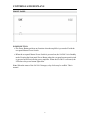
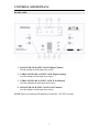
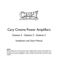
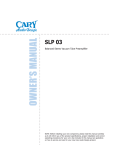
o o o o o o o o o o o o o o o o o o o o o o o o o o o o o o o o o o o o o o o o o o o o o o o o o o o o o o o o o o o o o o o o o o o o o o o o o OWNER’S MANUAL o o o o o o o o o o o o o o o o o o o o o o o o o o o o o o o o o o o o o o o o o o o o o o o o o o o o o o o o o o o o o o o o o o o o o o o o o SA-200.2 Power Amplifier NOTE: Before installing your new component, please read this manual carefully as it will inform you of the product specifications, proper installation and correct operating procedures for your unit. Also included in this manual are guidelines on how to service and care for your new Cary Audio Design product. TABLE OF CONTENTS Important Safety Instructions ............................................................2 Welcome Product Features.....................................................................................4 Unpacking and Installation ....................................................................6 Specifications ........................................................................................7 Controls & Displays Front Panel .............................................................................................8 Rear Panel ..............................................................................................9 Service and Care Care and Cleaning ................................................................................12 Factory Service ....................................................................................12 Non-Warranty Repairs .........................................................................12 Shipping Instructions ...........................................................................12 United States Limited Warranty ......................................................13 1 IMPORTANT SAFETY INSTRUCTIONS WARNING: The triangle with the lightning flash symbol displayed on the unit advises the user of dangerous uninsulated voltage inside the product’s enclosure. CAUTION: To reduce the risk of electric shock, do not remove the cover. There are no user-serviceable parts inside; it is recommended that only qualified personnel service this component. ALERT: The triangle with the exclamation point symbol on the component suggests that the owner refer to important operating and maintenance instructions in the owner’s manual. 1. 2. 3. 4. 5. 6. 7. 8. 9. 10. 11. 12. 13. 14. OWNER’S MANUAL: Before powering up the equipment, read all safety and operating instructions and follow them as instructed. Retain the safety and operating instructions for future reference. ATTACHMENTS: Use only those attachments recommended by the unit manufacturer, as others may cause hazards. ACCESSORIES: Do not place the unit on an unstable cart, stand, tripod, bracket, or table. The unit may fall, causing injury to a person or damage to the unit. Mount the unit according to the manufacturer’s instructions with the suggested mounting accessory. WALL OR CEILING MOUNTING: Mount the unit to a wall or ceiling only in the manner recommended by the manufacturer. WATER AND MOISTURE: Do not use the unit near water (for example, near a swimming pool, bath tub, wash bowl, kitchen sink, or laundry tub) or in a damp environment (like a basement or outside in the rain). OBJECT AND LIQUID ENTRY: Do not push objects of any kind into the unit through openings as they could touch dangerous voltage points and short-out parts, possibly resulting in a fire or electric shock. Avoid spilling liquid of any kind on the unit. If water or any metal object (such as a paper clip, coin, or staple) accidentally falls inside the unit, disconnect it from the AC power source immediately and contact Cary Audio Design for further instructions. HEAT: Position the unit away from heat sources such as radiators, heat registers, stoves, or other units (including amplifiers) that produce heat. VENTILATION: Slots and openings in the cabinet create ventilation to protect the component from overheating. These openings on the top and bottom panels must remain unobstructed. Allow at least 6 inches (16cm) of clearance above the unit and an opening behind the unit for airflow. Do not place the unit on a bed, sofa, rug, built-in bookcase, or rack without adequate ventilation. GROUNDING OR POLARIZATION: As a safety feature, the unit may be equipped with a polarized alternating current line plug in which one blade is wider than the other. This plug will fit into the power outlet only one way. If you cannot insert the plug fully into the outlet, try reversing the plug. If the plug still will not fit, contact a licensed electrician to update your obsolete outlet. Do not defeat the safety purpose of the polarized plug. POWER SOURCES: Operate the unit only from the power source indicated on the marking label. If you are unsure of the type of power supplied to your home, consult your unit dealer or local power company. POWER CORD PROTECTION: Arrange power supply cords so that they do not suffer from foot traffic or pinching by items placed on or against them. Pay close attention to cords where plug enter the AC outlet and where they exit from the unit. LIGHTNING: For added protection during a lightning storm or when is the component is idle for long periods of time, unplug the unit from the wall outlet and disconnect the antenna or cable system. This will help protect the unit from lightning and power line surge damage. POWER LINES: Do not locate an outside antenna system in the vicinity of overhead power lines or other electric light or power circuits. When installing an outside antenna system, take extreme care to avoid touching the power lines or circuits; contact with them could be fatal. OVERLOADING: Do not overload wall outlets, extension cords, or integral convenience receptacles as this increases the risk of fire or electric shock. 2 IMPORTANT SAFETY INSTRUCTIONS 15. REPLACEMENT PARTS: When replacement parts are required, be sure the service technician has used replacement parts specified by the manufacturer or those having the same characteristics as the original parts. Unauthorized substitutions may result in fire, electric shock or other hazards. 16. SAFETY CHECK: Upon completion of any service or repairs to the unit, ask the service technician to perform safety checks to ensure the unit is in proper operating condition. 17. IMPORTANT SAFETY NOTE: Before connecting a new product to your audio or home theater system, turn off all other equipment (preferably unplugging them from the AC power source). Many audio components feature automatic turn-on circuits that may activate during an installation, potentially causing damage to electronic components and/or speakers. This type of damage is not covered by product warranties, and Cary Audio specifically disclaims responsibility for any such damage. Power Cord: The removable power cord provided with your player was specifically designed for use with this product, but other AC cords may be used. Consult your dealer for advice on AC power cords and high quality wire in your system. Wiring: Cables running inside walls should have the appropriate markings to indicate compliance and listing by the UL, CSA or other standards required by the UL, CSA, NEC or your local building code. Questions about cables inside of walls should be referred to a qualified custom installer, a licensed electrician, or low-voltage contractor. 18. RECORDING COPYRIGHT: Recording of copyrighted material for other than personal use is illegal without permission of the copyright holder. 19. NOTE TO CATV SYSTEM INSTALLER: This reminder is provided to call the CATV system installer's attention to article 820-40 of the NEC, ANSI/NFPA 70, which provides guidelines for proper grounding and, in particular, specifies that the cable ground shall be connected to the grounding system of the building as close to the point of cable entry as practical. 20. FCC INFORMATION FOR USER: CAUTION: Any changes or modifications not expressly approved by Cary Audio Design could void the user's authority to operate the equipment. NOTE: This equipment has been tested and found to comply with the limits for a Class B digital device pursuant to Part 15 of the FCC Rules. These limits are designed to provide reasonable protection against harmful interference in a residential installation. This equipment generates and can radiate radio frequency energy, and if not installed and used in accordance with the instructions it may cause harmful interference to radio communications. However, there is no guarantee that interference will not occur in a particular installation. If this equipment does cause harmful interference to radio or television reception, which can be determined by turning the equipment off and on, the user is encouraged to try to correct the interference by one or more of the following measures: Reorient or relocate the receiving antenna. Increase the separation between the equipment and receiver. Connect the equipment into an outlet on a circuit different from where the receiver is connected. 21. OUTDOOR ANTENNA INSTALLATION/SAFE ANTENNA AND CABLE CONNECTION: If an outside antenna or cable system is connected to the equipment, be sure the antenna or cable system is grounded in order to provide protection against built-up static charges and voltage surges. Article 810 of the National Electrical Code, ANSI/NFPA 70 (in Canada, Part 1 of the Canadian Electrical Code) provides information regarding proper grounding of the mast and supporting structure, grounding of the lead-in wire to an antenna discharge unit, size of grounding conductors, location of antenna discharge unit, connection to grounding electrodes and requirements for the grounding electrode. outside antenna system should be located well away from power lines, electric light or power circuits and where it will never come into contact with these power sources if it should happen to fall. When installing an outside antenna, extreme care should be taken to avoid touching power lines, circuits or other power sources as this could be fatal. Because of the hazards involved, antenna installation should be left to a professional. 3 WELCOME PRODUCT FEATURES Thank you for purchasing the SA-200.2 power amplifier. The introduction of the SA-200.2 solid-state power amplifier represents an all new amplifier design. It embodies a new modular approach that ensures consistency in performance, and ease of manufacture and serviceability. In implementing the new design, we have dramatically improved performance and current-handling capacity over our previous models while still maintaining the highest levels of sonic quality. The SA-200.2 is a 200 watt stereo amplifier into 8 ohms, (350 watts into 4 ohms), with balanced and single ended inputs. The amplifier exhibits very high current capability, is stable into low impedance loads, and features 3 dB of dynamic headroom. When we designed the SA-200.2 power amplifier, one of our primary goals was to create a product that would give years of consistent and reliable use without any maintenance. To achieve that goal we took a hard look at the design and choice of components. For example, we use high-precision metal film resistors in almost all our circuitry, even in places where their use is not required. We have overbuilt the output stage and increased the heat dissipating capabilities of the amplifiers by as much as 50% over our previous designs. The changes encompass almost every part of the design, down to the choice of thickness of the chassis sheet metal. The monolithic front end brought major advantages to the amplifier design with improved temperature stability, low offset, and a substantial reduction of all types of distortion across the full frequency spectrum. Cary Audio Design has been known for over two decades as a producer of some of the finest and most musical tube amplifiers in the world. Based on this heritage we have paid special attention to the sonic qualities of these new solid-state amplifiers, voicing them to have the proven attributes of the “Cary Sound” and testing them hundreds of hours with many different speakers. In our quest to dramatically improve them over our previous efforts we compared them to some of the best of the competition, often at much higher price points. This took months of research and development time but we would not rest until we were satisfied that we had surpassed our previous models by a wide margin. The improvements in the power supply have brought gains in bass performance, which is now much more visceral and controlled even into difficult loads. Reducing the noise floor, increasing the isolation between the channels, and especially redesigning the sensitive front end of the amplifier has improved imaging, sound staging and depth retrieval. The midrange is now more lifelike and palpable. One area of which we are particularly proud is what we have achieved in transparency, and the way images now hang in three dimensional space. The amplifiers were designed to be equally at home in a highperformance music system or a home cinema setting. 4 WELCOME The SA-200.2 power amplifier features include: Single-ended RCA or XLR balanced inputs 2x 200 Watts/8 ohms; 2x 350 Watts/4 ohms Remote trigger (works with +3.3 to +24 Volts DC) Overbuilt power supply employs a massive 1500 kVA power transformer and in excess of 82,000 uF of capacitance Protection against short circuits, device failures, miswiring, and internal faults. Thermal as well as DC offset protection Matched output transistors Stable with mismatched, reactive or unusual loads Soft start circuit prevents “Brown outs” when amplifier is turned on High quality RCA (gold plated) and XLR input connectors High-quality, heavy-duty speaker output connectors Our goals in designing this new amplifier were quite extensive, and we believe we met or exceeded all of them. As a company we strive to be on the cutting edge of our industry, which requires a lot of research and dedication on our part to bring you the best products possible. We are confident that the SA-200.2 is a superb amplifier that will meet the tests of musical accuracy, dynamic performance, and long-term reliability. 1020 Goodworth Drive Apex, NC 27539 Phone 919.355.0010 Fax 919.355.0013 www.caryaudio.com 5 WELCOME UNPACKING AND INSTALLATION Unpacking Your Cary Audio Design product was shipped in a carton particularly designed to protect its contents, and special care has been taken to prevent damage during shipping. Carefully remove your new component from its packing carton and examine it closely for signs of shipping damage. If shipping damage is discovered, document the damage with photographs, contact the transport carrier immediately, and retain the packing as evidence. We strongly recommend saving all original packing cartons to protect your component for storage or future shipping. Power Requirement The SA-200.2 is designed to operate from AC mains current. The specified AC voltage is either 110-120 volts or 220-240 volts AC at 50-60 Hz. Cables The speaker cables from the output posts of the SA-200.2 power amplifier to the speaker system can be any length, as your speaker set-up requires. Select speaker cables of sufficient size to preserve the outstanding performance capabilities of your SA-200.2 power amplifier. Heavy gauge #14 wire is suitable for distances up to 10 feet, #12 for 25 feet. Most audio dealers will have proper speaker cable in stock for this purpose. Consult your Authorized Cary Audio Design dealer for advice about wire. Interconnects Signal input connections are made via the input jack on the rear of the SA-200.2 power amplifier, either single-ended or balanced. The interconnect cables from the output of the processor can be any convenient length your installation set-up requires. The choice of a high quality interconnect cable is important. Once again, your audio dealer will have the proper cables in stock for this purpose. Warranty Card If you are the original purchaser of this unit and you purchased it in the United States, fill out the enclosed warranty registration card and return it to Cary Audio Design within 15 days of your purchase. Warranty restrictions apply. Consult the warranty section of this manual for details. Please keep a copy of the original sales receipt from your Authorized Cary Audio Design dealer to validate the warranty if necessary. WARNING - Do not touch the speaker output binding posts during normal operation. You may be shocked. Do not short-circuit the speaker output binding posts. Damage may occur or the fuse may blow. Do not parallel or “bridge” the speaker output binding posts as this will damage the amplifier. 6 SPECIFICATIONS Operating the SA-200.2 amplifier is a simple procedure since each unit is designed for long-term stability in virtually any home operating situation. However, if the unit is operated outside the parameters outlined in this owner’s manual, damage may occur. Please read this manual carefully before operating your new SA-200.2. GENERAL SPECIFICATIONS ................................................................................................................................................ Circuit Type Solid State, Class A/B ................................................................................................................................................ Power Output 2 x 200 Watts @ 8 Ohms from 20 Hz to 20 kHz 2 x 350 Watts @ 4 Ohms from 20 Hz to 20 kHz ................................................................................................................................................ Frequency Response 10 Hz to 50 kHz +/- 0.1 dB ................................................................................................................................................ Signal-to-Noise Ratio >100 dB, “A” Weighted ................................................................................................................................................ Input Impedance 22K Ohms – Unbalanced ( RCA jacks) 22K Ohms - Balanced (XLR) ................................................................................................................................................ Voltage Gain 28 dB ................................................................................................................................................ AC Power 117/234 Volts AC @50-60 Hz ................................................................................................................................................ Break-in Time 100 Hours of playing time ................................................................................................................................................ Finish Black epoxy coated steel chassis. Silver anodized aluminum faceplate. (Black Optional) ................................................................................................................................................ Weight 65 lbs ................................................................................................................................................ Dimensions 7.5” H x 17.7” W x 19.5” D ................................................................................................................................................ Audio Input 2 RCA jacks, 2 XLR jacks ................................................................................................................................................ Audio Output 2 pair Heavy-Duty, gold-plated binding posts ................................................................................................................................................ THD Less than 0.05% at rated output ................................................................................................................................................ Damping Factor Greater than 400 from 10Hz to 20 kHz ................................................................................................................................................ Remote Trigger 3.3-24v DC at 5mA or greater 7 CONTROLS AND DISPLAYS FRONT PANEL POWER BUTTON The Power Button performs no function when the amplifier is powered off with the rear panel Master Power Switch. When the rear panel Master Power Switch is powered on, the SA-200.2 is in Standby mode. Pressing the front panel Power Button when the rear panel master panel switch is powered on will activate the power amplifier. When the SA-200.2 is activated, the LED above the power button lights blue. Note: When the status of the SA-200.2 changes, relay clicks may be audible. This is normal. 8 CONTROLS AND DISPLAYS REAR PANEL 1. BALANCED (XLR) INPUT JACK (Right Channel) Provides balanced audio input from source. 2. UNBALANCED (RCA) INPUT JACK (Right Channel) Provides balanced audio input from source. 3. UNBALANCED (RCA) INPUT JACK (Left Channel) Provides unbalanced audio input from source. 4. BALANCED (XLR) INPUT JACK (Left Channel) Provides balanced audio input from source. NOTE: Please use balanced OR unbalanced connectors. Do NOT use both. 9 CONTROLS AND DISPLAYS Never make or break connections to the SA-200.2 unless the SA-200.2 and all associated components are powered off. Do not connect the outputs of the SA-200.2 to the outputs of other amplifiers. 5. LEFT AND RIGHT SPEAKER OUTPUT CONNECTORS Provide audio output for the speakers. Output connectors can accept bare speaker wires or most spade and banana connectors. When using bare speaker wires, loosen the connector, insert the wire into the receptacle, and tighten the connector. The same procedure should be used for spade connectors. 6. FUSE HOLDER Use only 8A (120v) or 4A (240v) 7. AC POWER CONNECTOR/ MAIN POWER SWITCH Connect to AC mains using the included power supply cord. Turn the main power switch on before use. 8. REMOTE TRIGGER INPUT Enables the SA-200.2 to be controlled by an external device with a 3.3V DC minimum to 24V DC maximum trigger output. Connect the trigger output of the external device to the TRIGGER INPUT of the SA-200.2 power amplifier. The SA-200.2 will automatically respond when the external device is powered on and off. When the controlling device is turned on, the amplifier will turn on after a delay. This delay is intentional and serves to protect the speakers while the unit stabilizes. During start-up, you may hear a relay clicking. This is normal. 10 CONTROLS AND DISPLAYS CONNECTING TO A SUBWOOFER The subwoofer should be connected to the preamplifier or processor through its low level inputs. Do not under any circumstances connect the amplifier to a subwoofer through its high level (speaker) inputs. There is a potential of damaging the amplifier using this type of connection due to differences in grounding schemes used by some subwoofer manufacturers. Failing to observe the following precaution will void your warranty. 11 SERVICE AND CARE CARE AND CLEANING Unplug the unit from the wall outlet. Clean the cabinet housing and front panel of the SA-200.2 with a soft cloth and a glass cleaner (such as Windex). Removing the cover during cleaning is not advised. The frequency of cleaning will vary based on the cleanliness of the environment and the number of hours the SA-200.2 is operated. FACTORY SERVICE Careful consideration has been given to the design of your SA-200.2 to keep maintenance problems to a minimum. Any problems or requests for service should be referred to our Customer Service Department at 919.355.0010. Do not return the SA-200.2 to the factory without a return authorization number (RA) from the Customer Service Department. Refer to the next section for details about returning equipment to Cary Audio Design. Should the unit be lost or damaged in shipment, Cary Audio Design will assume no responsibility if the shipping company refuses to pay for damage due to your improper packing or lack of insurance. Please use the original shipping carton for shipping the player. NON-WARRANTY REPAIRS Cary Audio Design will provide repair service for its products charging on a time and expense basis. Please call Cary Audio Design at 919.355.0010 for more information about out-of-warranty service and repair fees. SHIPPING INSTRUCTIONS In the event that the owner needs to return the unit to Cary Audio Design for service or repair of a possible defect, he must follow the following steps: 1. Contact Cary Audio Design at 919.355.0010 to obtain a Return Authorization (RA) number prior to shipping; include this number with the package. 2. Submit a copy of the original sales receipt; blank receipts will not validate the limited warranty for service by Cary Audio Design. The original sales receipt must contain the following information: the authorized Cary Audio Design dealer’s name the date of purchase the unit’s sales price the buyer’s name and address 3. Describe in detail the problem. 4. Note the unit’s model number and serial number. 5. Ship or deliver: With all freight and insurance charges prepaid and in its original packing container or equivalent, ship the component to: Cary Audio Design - 1020 Goodworth Drive, Apex, NC 27539 12 UNITED STATES LIMITED WARRANTY Cary Audio Design warrants to the original United States purchaser for use in the United States that Cary Audio Design vacuum tube or solid-state power amplifiers, surround sound processors, or preamplifiers shall be free from defects in parts or workmanship for three years from the date of the original purchase. Vacuum tubes, if any are used in the component, are offered a 90-day (from purchase date) exchange policy against defects with the exception of the CAVT 300B vacuum tube that has a one-year (from purchase date) exchange policy. Any digital drive design, whether a Cary Audio Design CD or SACD player or a Cary Cinema DVD player, has a limited one-year parts and labor warranty against defects in manufacturing. This is a limited warranty offered only to the original purchaser and does not transfer. During the limited warranty period, Cary Audio Design or an authorized Cary Audio Design service facility will provide free of charge both parts and labor necessary to correct any defects in material or workmanship. To obtain such warranty service, the original purchaser must complete and send in the Warranty Registration Card within 15 days of purchase. WARRANTY DISCLAIMER Except for the express warranties stated herein, Cary Audio Design disclaims all other warranties including, without limitation, all implied warranties of merchantability and fitness for a particular purpose. The foregoing constitutes Cary Audio Design’s entire obligation with respect to this product, and the original purchaser and any user or owner shall have no other claim for incidental or consequential damages. Some states do not allow the exclusion or limitation of incidental or consequential damages, so the above limitation and exclusion may not apply to you. This warranty gives legal rights and you may also have other rights, which vary from state to state. Proper maintenance, repair and use are important to obtain performance from this product. Therefore, please carefully read the Operating Manual. This warranty does not apply to any defect that Cary Audio Design in its sole discretion determines was caused by any of the following: Improper maintenance or repair, including the installation of parts or accessories that do not conform to the quality and the specifications of the original parts Misuse, abuse, neglect or improper installation Accidental or incidental damage EXCLUSIVE REMEDY Notwithstanding the foregoing, the purchaser’s exclusive remedy for any breach of warranty, express or implied, is limited to the repair or replacement of the defective unit or the refund of the purchase price, at the option of Cary Audio Design. Under no circumstances is Cary Audio Design liable for incidental or consequential damages. Any implied warranties imposed by law terminate one year from the date of purchase. 13 UNITED STATES LIMITED WARRANTY INTERNATIONAL PURCHASERS (Export markets) Cary Audio Design warrants its merchandise to purchasers within the United States exclusively for use within the United States of America. It provides no other warranties, expressed or implied. If you are living outside the USA, please consult your local dealer or distributor to determine the details of your local warranty. Cary Audio Design 1020 Goodworth Drive Apex, NC 27539 Phone 919.355.0010 Fax 919.355.0013 www.caryaudio.com 14 Notes 15 Notes 16 1020 Goodworth Drive, Apex, NC 27539 phone 919-355-0010 fax 919-355-0013 www.caryaudio.com o o o o o o o o o o o o o o o o o o o CARY AUDIO DESIGN o o o o o o o o o o o o o o o o o o o o o o o o o o o o o o o o o o o o o o o o o o o o o o o o o o o o o o o o o o o o o o o o o o o o o o o o o