1
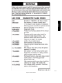
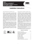
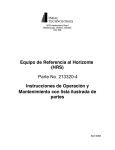
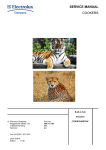
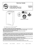
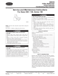
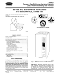
58HDX
4---WAY MULTIPOISE FIXED SPEED
CONDENSING GAS FURNACE
Service Guide
TABLE OF CONTENTS
PAGE
ama
SAFETY CONSIDERATIONS . . . . . . . . . . . . . . . . . . . . . . . . . 1
CERTIFIED
GENERAL . . . . . . . . . . . . . . . . . . . . . . . . . . . . . . . . . . . . . . . . . 2
ELECTROSTATIC DISCHARGE (ESD) PRECAUTIONS . . . 2
NOTE: Read the entire instruction manual before starting the
installation. .
!
ELECTRICAL
HAZARD
CARE AND MAINTENANCE . . . . . . . . . . . . . . . . . . . . . . . . . 3
Cleaning and/or Replacing Air Filter . . . . . . . . . . . . . . . . . . . . 3
Blower Motor and Wheel Maintenance . . . . . . . . . . . . . . . . . . 3
WARNING
SHOCK,
FIRE,
OR
Cleaning Burners . . . . . . . . . . . . . . . . . . . . . . . . . . . . . . . . . . . 4
Cleaning Heat Exchangers . . . . . . . . . . . . . . . . . . . . . . . . . . . 15
EXPLOSION
Primary Heat Exchangers . . . . . . . . . . . . . . . . . . . . . . . . 15
Secondary Heat Exchangers . . . . . . . . . . . . . . . . . . . . . . 15
Failure to follow warnings could result in personal injury,
death, or property damage.
Flushing Collector Box and Drainage System . . . . . . . . . . . . 15
Before servicing, disconnect all electrical power and gas
supply to furnace. Lockout and tag with appropriate label.
Servicing Hot Surface Igniter . . . . . . . . . . . . . . . . . . . . . . . . . 16
Electrical Controls And Wiring . . . . . . . . . . . . . . . . . . . . . . . 18
When servicing controls, label all wires prior to disconnecting.
Reconnect wires correctly.
Checking Heat Tape Operation (If Applicable) . . . . . . . . . . . 18
Winterizing . . . . . . . . . . . . . . . . . . . . . . . . . . . . . . . . . . . . . . 18
Verify proper operation after servicing.
WIRING DIAGRAM . . . . . . . . . . . . . . . . . . . . . . . . . . . . . . . . 18
!
ELECTRICAL
HAZARD
WARNING
SHOCK,
FIRE
OR
EXPLOSION
Failure to follow this warning could result in property damage,
personal injury, or death.
The ability to properly perform maintenance on this equipment
requires certain expertise, mechanical skills, tools, and
equipment. If you do not possess these, do not attempt to
perform any maintenance on this equipment other than those
procedures recommended in the User’s Manual.
TROUBLESHOOTING . . . . . . . . . . . . . . . . . . . . . . . . . . . . . . 18
SAFETY CONSIDERATIONS
Recognize safety information. This is the safety-alert symbol. !
When you see this symbol on the furnace and in instructions or
manuals, be alert to the potential for personal injury.
Understand the signal words DANGER, WARNING, CAUTION,
and NOTE. These words are used with the safety-alert symbol.
DANGER identifies the most serious hazards which will result in
severe personal injury or death. WARNING signifies hazards
which could result in personal injury or death. CAUTION is used
to identify unsafe practices which would result in minor personal
injury or product and property damage. NOTE is used to highlight
suggestions which will result in enhanced installation, reliability,
or operation.
1
!
ELECTROSTATIC DISCHARGE (ESD)
PRECAUTIONS
WARNING
FIRE / EXPLOSION HAZARD
!
Failure to follow this warning could cause personal injury,
death, or property damage.
UNIT DAMAGE HAZARD
Never store anything on, near, or in contact with the furnace,
such as:
Failure to follow this caution may damage furnace
components.
1. Spray or aerosol cans, rags, brooms, dust mops, vacuum
cleaners, or other cleaning tools.
Electrostatic discharge can affect electronic components. Take
precautions during furnace installation and servicing to protect
the furnace electronic control. Precautions will prevent
electrostatic discharges from personnel and hand tools which
are held during the procedure. These precautions will help to
avoid exposing the control to electrostatic discharge by putting
the furnace, the control, and the person at the same
electrostatic potential.
2. Soap powders, bleaches, waxes or other cleaning
compounds, plastic or plastic containers, gasoline, kerosene,
cigarette lighter fluid, dry cleaning fluids, or other
volatile fluids.
58HDX
3. Paint thinners and other painting compounds, paper bags, or
other paper products.
Installing and servicing heating equipment can be hazardous due to
gas and electrical components. Only trained and qualified
service agency personnel should install, repair, or service
heating equipment. Untrained personnel can perform basic
maintenance functions described in User’s Information
Manual such as cleaning and replacing air filters. All other
operations must be performed by trained and qualified service
agency personnel. When working on heating equipment, observe
precautions in the literature, on tags, and on labels attached to or
shipped with the unit and other safety precautions that may apply.
Follow all safety codes including the National Fuel Gas Code
(NFGC) NFPA 54--2006/ANSI Z223.1--2006 in the USA;
National Standard of Canada, Natural Gas and Propane Installation
Code CSA B149.1 (NSCNGPIC) in Canada; and the Installation
Standards, Warm Air Heating and Air Conditioning Systems
(NFPA 90B) ANSI/NFPA 90B. Wear safety glasses and work
gloves. Have a fire extinguisher available during start-up and
adjustment procedures and service calls.
!
ELECTRICAL
HAZARD
AIRFLOW
UPFLOW
AND
UNIT
HORIZONTAL
RIGHT
HORIZONTAL
LEFT
DOWNFLOW
AIRFLOW
AIRFLOW
A93041
AIRFLOW
CAUTION
SHOCK
CAUTION
Fig. 1 -- Multipoise Orientations
1. Disconnect all power to the furnace. DO NOT TOUCH
THE CONTROL OR ANY WIRE CONNECTED TO THE
CONTROL PRIOR TO DISCHARGING YOUR BODY’S
ELECTROSTATIC CHARGE TO GROUND.
2. Firmly touch a clean, unpainted, metal surface of the
furnace chassis which is close to the control. Tools held in a
person’s hand during grounding will be satisfactorily
discharged.
3. After touching the chassis you may proceed to service the
control or connecting wires as long as you do nothing that
recharges your body with static electricity (for example; DO
NOT move or shuffle your feet, DO NOT touch
ungrounded objects, etc.).
4. If you touch ungrounded objects (recharge your body with
static electricity), firmly touch furnace again before
touching control or wires.
5. Use this procedure for installed and uninstalled
(ungrounded) furnaces.
6. Before removing a new control from its container, discharge
your body’s electrostatic charge to ground to protect the
control from damage. If the control is to be installed in a
furnace, follow items 1 through 5 before bringing the
control or yourself into contact with the furnace. Put all
used AND new controls into containers before touching
ungrounded objects.
DAMAGE
Failure to follow this caution may result in personal injury or
damage to furnace.
Label all wires prior to disconnection when servicing controls.
Wiring errors can cause improper and dangerous operation.
GENERAL
This furnace van be installed as a direct vent (2-pipe) or
non-direct vent (1-pipe) condensing gas furnace. These
instructions are written as if the furnace is installed in an upflow
application. An upflow furnace application is where the blower is
located below the combustion and controls section of the furnace,
and conditioned air is discharged upward. Since this furnace can be
installed in any of the 4 positions shown in Fig. 1, you may need to
revise your orientation to component location accordingly.
2
2. Remove blower door.
3. Slide filter out of furnace (See Fig. 2 and 3).
4. Furnaces are equipped with permanent, washable filter(s).
Clean filter by spraying cold tap water through filter in
opposite direction of airflow.
5. Rinse filter and let dry. Oiling or coating of filter is not
recommended.
6. Slide filter into furnace.
7. Replace blower door.
8. Turn on electrical supply to furnace.
7. An ESD service kit (available from commercial sources)
may also be used to prevent ESD damage.
CARE AND MAINTENANCE
For continuing high performance and to minimize possible
equipment failure, it is essential that maintenance be performed
annually on this equipment. Consult your local dealer about proper
maintenance and maintenance contract availability.
WARNING
ELECTRICAL SHOCK HAZARD
Failure to follow this warning could result in personal injury
or death.
Turn off the gas and electrical supplies to the unit before
performing any maintenance or service. Lockout and tag with
appropriate label. Follow the operating instructions on the
label attached to the furnace.
The minimum maintenance that should be performed on this
equipment is as follows:
1. Check and clean or replace air filter each month as needed.
2. Check blower motor and wheel for cleanliness annually.
3. Check electrical connections for tightness and controls for
proper operation each heating season. Service as necessary.
4. Check for proper condensate drainage. Clean as necessary.
5. Check for blockages in combustion-air and vent
pipes annually.
6. Check burners for cleanliness annually.
!
CAUTION
CUT HAZARD
Failure to follow this caution may result in personal injury.
Be careful of sharp metal edges, etc. Use care and wear
protective clothing, safety glasses, and gloves when
removing parts.
Procedure 1 — Cleaning and/or Replacing
Air Filter
The air filter arrangement may vary depending on the application
or orientation.
!
FIRE, CARBON
HAZARD
WARNING
MONOXIDE
AND
POISONING
Failure to follow this warning could result in property damage,
personal injury, or death.
Never operate unit without a filter or with the blower access
panel removed. Operating a unit without a filter or with the
blower access door removed could cause damage to the
furnace blower motor. Dust and lint on internal parts of
furnace can cause a loss of efficiency.
NOTE: If filter has cross-mesh binding, binding must face blower.
If filter has an air direction arrow, arrow must point toward blower.
To clean or replace the filters, proceed as follows:
1. Turn off electrical supply to furnace.
Procedure 2 — Blower Motor and Wheel
Maintenance
To ensure long life, economy, and high efficiency, clean
accumulated dirt and grease from blower wheel and
motor annually.
The inducer and blower motors are pre-lubricated and require no
additional lubrication. These motors can be identified by the
absence of oil ports on each end of the motor.
The following items should be performed by a qualified service
technician.
Clean blower motor and wheel as follows:
1. Turn off electrical supply to furnace.
2. Remove blower door.
3. Disconnect blower motor wires from furnace control board.
Field thermostat connections may need to be disconnected
depending on their length and routing.
4. Remove control box mounting screws, and position control
box, transformer, and door switch assembly to right side of
furnace casing.
5. If condensate trap is located in left-or right-hand side of
furnace casing, proceed to item 6, otherwise remove trap
and tubing as described below. (See top Fig. 6, 7, or 8.)
a. Disconnect field drain connection from condensate trap.
b. Disconnect drain and relief port tubes from
condensate trap.
c. Remove condensate trap from blower shelf.
6. Remove screws securing blower assembly to blower shelf
and slide blower assembly out of furnace.
7. Clean blower wheel and motor by using a vacuum with soft
brush attachment. Be careful not to disturb balance weights
(clips) on blower wheel vanes. Do not bend wheel or blades
as balance will be affected.
8. If greasy residue is present on blower wheel, remove wheel
from the blower housing and wash it with an appropriate
degreaser. To remove wheel:
a. Mark blower wheel location on shaft before disassembly
to ensure proper reassembly.
b. Loosen setscrew holding blower wheel on motor shaft.
NOTE: Mark blower mounting arms and blower housing so each
arm is positioned at the same hole location during reassembly.
c. Mark blower wheel orientation and cutoff plate location
to ensure proper reassembly.
d. Remove screws securing cutoff plate and remove cutoff
plate from housing.
e. Remove bolts holding motor mounts to blower housing
and slide motor and mounts out of housing. Disconnect
capacitor and ground wire attached to blower housing
before removing motor. Motor mounts need not be
removed from motor.
3
58HDX
!
NOTE: Ensure tubes are not kinked or pinched, as this will
affect operation.
c. Connect field drain to condensate trap.
13. Reconnect wires.
Refer to furnace wiring diagram, and connect thermostat leads if
previously disconnected. (See Fig.20.)
Center Clip
side-to-side
!
CAUTION
UNIT DAMAGE HAZARD
Failure to follow this caution may result in unit component
damage.
Heating speed selection MUST be adjusted to provide proper
temperature rise as specified on the rating plate.
9”
A07691
(228.6 mm)
Table 1 – Speed Selector
58HDX
Fig. 2 -- Bottom Filter Arrangement
SPEED
FACTORY
ATTACHED TO
Black
High
Cool
Orange
Medium High
Heat
Blue
Medium Low
M1
Red
Low
M2
White
Common
Com
COLOR
14. Turn on electrical supply. Manually close blower access
door switch. Use a piece of tape to hold switch closed.
Check for proper rotation by jumpering R to G.
Filter Rack
End Cap
!
ELECTRICAL SHOCK HAZARD
A07690
Failure to follow this warning could result in personal injury
or death.
Fig. 3 -- Filter Installed for Side Inlet
Blower access door switch opens 115-v power to furnace
control. No component operation can occur. Caution must be
taken when manually closing this switch for service purposes.
f. Remove blower wheel from housing.
!
CAUTION
15. If furnace is operating properly, remove tape to release
blower access door switch, remove jumper across R to G,
and replace blower access door.
UNIT DAMAGE HAZARD
Failure to follow this caution may result in furnace component
failure.
The blower wheel should not be dropped or bent as balance
will be affected.
9.
10.
11.
12.
g. Clean wheel per instructions on degreaser cleaner. Do
not get degreaser cleaner in motor.
Reassemble motor and blower wheel by reversing items 8b
through 8f. Ensure wheel is positioned for proper rotation.
Be sure to reattach ground wire. Tighten setscrew to 140 to
160 in.--lb torque.
Reinstall blower assembly in furnace.
Reinstall control box, transformer, and door switch
assembly on blower shelf.
Reinstall condensate trap and tubing if previously removed.
a. Reinstall condensate trap in hole in blower shelf.
b. Connect condensate trap drain tubes. See Fig. 6, 7, or 8.
WARNING
Procedure 3 — Cleaning Burners
The following items should be performed by a qualified service
technician. If burners develop an accumulation of light dirt or dust,
they may be cleaned by using the following procedure:
1. Turn off gas and electrical supplies to furnace.
2. Remove main furnace door.
3. Using backup wrench, disconnect gas supply pipe from
furnace gas control valve.
!
CAUTION
ELECTRICAL SHOCK, UNIT DAMAGE HAZARD
Failure to follow this caution may result in personal injury or
furnace component damage.
Label all wires prior to disconnection when servicing controls.
Wiring errors can cause improper and dangerous operation.
4
!
CELL PANEL
WARNING
FIRE, EXPLOSION, UNIT DAMAGE HAZARD
BURNERS
Failure to follow this warning could result in property damage,
personal injury, or death.
Gas valve switch MUST be facing forward or tilted upward.
14. Turn on gas and electrical supplies to furnace.
!
BURNER BOX
MANIFOLD
FIRE OR EXPLOSION HAZARD
A07826
Fig. 4 -- Burner Box Assembly
Never test for gas leaks with an open flame. Use a
commercially available soap solution made specifically for the
detection of leaks to check all connections.
4. Remove wires from gas valve. Note location for reassembly.
5. Unplug igniter from harness.
6. Remove screws that secure manifold to burner box.
(See Fig. 4.)
NOTE: Do not remove burner box from cell panel.
7. Remove manifold, orifices, and gas valve as 1 assembly.
8. Remove screws attaching burner assembly in burner box.
NOTE: Use care when removing and reinstalling burners not to
strike the hot surface igniter.
9. Remove burner assembly from burner box.
NOTE: All burners are attached to burner bracket and can be
removed as 1 assembly.
10. Clean burners with soft brush and vacuum.
11. Reinstall manifold, orifice, and gas valve assembly in
burner box. Ensure burners fit over orifices.
15. Check for gas leaks.
16. Replace main furnace door.
PRIMARY HX
INLET OPENINGS
WARNING
ELECTRICAL SHOCK HAZARD
Failure to follow this warning could result in personal injury
or death.
Igniter wires must be securely placed in slot in manifold
grommet or else they could become pinched or severed and
electrically shorted.
12. Reconnect wires to gas valve and igniter. Refer to furnace
wiring diagram for proper wire location.
13. Reinstall gas supply pipe to furnace gas control valve using
backup wrench on gas valve to prevent rotation and
improper orientation.
NOTE: Use propane gas resistant pipe dope to prevent gas leaks.
DO NOT use Teflon tape.
A07827
Fig. 5 -- Cleaning Inlet Openings of Primary Heat Exchangers
5
58HDX
Failure to follow the safety warnings could result in personal
injury, death, or property damage.
GAS VALVE
!
WARNING
EXHAUST
INLET
Plastic Caps (2)
Yellow or black
On Some Models
ONLY
Coupling & Clamps
(Optional)
Vent Drain
& Clamps
Single Pressure Switch
VE
NT
IN
OFF
Dual Pressure Switch Detail
AIR FLOW
ON
Relief Tube
Black Rubber 3/16″
(4.8mm) ID
Drain Tee
58HDX
Drain Tube
Black Rubber
1/ ″ (12.7mm) ID &
2
Clamps
Drain Tube
Corrugated
5/ ″ (15.9mm) ID &
8
Clamps
Street Elbow
1/ ″ (12.7mm) CPVC
2
(Loose parts bag)
Drain Connector Black PVC
3/ ″ (18.1mm) PVC X 1/ ″
4
2
(12.7mm) CPVC (Loose
parts bag)
Casing Grommet
Black Rubber
5/ ″ (15.9mm) ID
8
(Loose parts bag)
Drain Line Vent Tee 3/4″
(18.1mm) PVC or 1/2″ (12.7mm)
CPVC (Field supplied)
Drain Tube Black Rubber 5/8″ (15.9mm) ID &
Clamps, Cut length to fit (Loose parts bag)
Representative drawing only, some models may vary in appearance.
25--24--67
A07706
Fig. 6 -- Upflow Installations Top Vent
6
Plastic Cap
Yellow or black
On Some Models
ONLY
INLET
2″ (50.8mm) PVC
Coupling
Vent Drain
& Clamps
Single Pressure Switch
VE
NT
IN
Either: The PVC
Drain Tee or a field
supplied 2″
(50.8mm) PVC Tee
EXHAUST
Coupling & Clamps
(Optional)
ON
OFF
Dual Pressure Switch Detail
58HDX
AIR FLOW
Relief Tube
Black Rubber 3/16″
(4.8mm) ID
Tee Trap White PVC
(loose parts bag)
Drain Tube
Black Rubber
(12.7mm) ID
& Clamps
1/ ″
2
Drain Connector Black PVC
(19.1mm) PVC X 1/2″
(12.7mm) CPVC
(Loose parts bag)
Drain Tube
Corrugated
5/ ″ (15.9mm) ID
8
& Clamps
3/ ″
4
SIDE VIEW
Rotate downward
5° to 10°
Casing Grommet
Black Rubber
5/ ″ (15.9mm) ID
8
(Loose parts bag)
NOTE: Built--in channel will
be angled 5° to 10° also.
Drain Line Vent Tee 3/4″ (18.1mm) PVC or 1/2″
(12.7mm) CPVC (Field supplied)
25--24--67a
Representative drawing only, some models may vary in appearance.
A07707
Fig. 7 -- Upflow Installations Vent Through Left Side
7
Plastic Cap
Yellow or black
INLET
On Some Models
ONLY
Dual Pressure Switch
Vent Drain
& Clamps
Relief Tube
Black Rubber
3/ ″ 〈4.8mm) ID
16
Either: The PVC Drain
Tee or a field supplied
2″ (50.8mm) PVC Tee
VE
NT
IN
Single Pressure Switch Details
ON
Drain Tube
Corrugated
5/ ″ (15.9mm) ID &
8
Clamps
AIR FLOW
58HDX
2″ (50.8mm)
PVC
Coupling
EXHAUST
OFF
Tee Trap White PVC
(loose parts bag)
Elbow Tubes (2) Black Rubber
1/ ″ (12.7mm) ID & Clamps
2
(loose parts bag)
Barbed Coupling, 1/2″ (12.7mm) OD
(loose parts bag)
SIDE VIEW
Rotate
downward
5° to 10°
Drain Line Vent Tee 3/4″
(18.1mm) PVC or 1/2″
(12.7mm) CPVC (Field supplied)
Drain Connector Black PVC
3/ ″ (19.1mm) PVC X 1/ ″
4
2
(12.7mm) CPVC
(Loose parts bag)
Casing Grommet
Black Rubber 5/8″ (15.9mm) CPVC
25--24--68
(Loose parts bag)
NOTE: Built--in channel will
be angled 5° to 10° also.
A07708
Fig. 8 -- All Models Vent Through Right Side (Upflow)
8
SIDE VIEW
Plastic Cap
Yellow or black
EXHAUST
Coupling & Clamps
(Optional)
Rotate downward
5° to 10°
2″ (51 mm) PVC Coupling
NOTE: Built--in channel will
be angled 5° to 10° also.
Either: The PVC
Drain Tee or a field
supplied 2″ (51 mm)
PVC Tee
Dual Pressure Switch
Relief Tube
Black Rubber 3/16″ (5 mm) ID
AIR FLOW
AIR FLOW
Single Pressure Switch Detail
On Some Models
ONLY
INLET
Tee Trap White PVC
(loose parts bag)
Drain Tube
Black Rubber
1/ ″ ID (13 mm) & Clamps
2
Flexible Tubing Connector,
3/ ″ (5 mm) OD (loose parts bag)
16
Elbow Tube Black Rubber
1/ ″ ID (13 mm) & Clamps
2
(Loose Parts Bag)
OFF
WARNING
Move Caps to
top of trap
Relief Tube,
Extension Black Rubber,
3/ ″ (5 mm) ID Cut to fit
16
(loose parts bag)
ON
Trap Connection
“Clamp ears”
Pointed OUT
Drain Tube Black, 5/8″ (16 mm) ID Corrugated
Cut at straight section
Leave room for clamp
Cut Here
Barbed Coupling 1/2″ (13 mm) OD
(loose parts bag)
Preassemble &
insert into furnace
25--24--69
A07767
Fig. 9 -- Downflow Left Side Vent and Trap
9
58HDX
Vent Drain
& Clamps
Plastic Cap
Yellow or black
Trap Connection
Elbow Tube Black Rubber
(13 mm) ID & Clamps
(Loose Parts Bag)
Vent Drain
& Clamps
1/ ″
2
Relief Tube
Black Rubber
3/ ″ (5 mm) ID
16
SIDE VIEW
Barbed Coupling
1/ ″ (13 mm) OD
2
(Loose Parts Bag)
Rotate downward
5° to 10°
Preassemble &
insert into furnace
Coupling & Clamps
(Optional)
Drain Hose
Black Rubber
1/ ″ (13 mm) ID Cut to
2
Fit & Clamps
INLET
NOTE: Built--in channel will
be angled 5° to 10° also.
On Some
Models
ONLY
2″ (51 mm) PVC Coupling
Either: The PVC
Drain Tee or a field
supplied 2″ (51 mm) PVC Tee
Single Pressure Switch Detail
AIR FLOW
FLOW
ON
AIR
Drain Tube Corrugated
Black, 5/8″ (16 mm)
ID & Clamps
OFF
58HDX
Dual Pressure Switch
“Clamp ears”
Pointed OUT
Tee Trap White PVC
(loose parts bag)
Drain Connector Black
PVC 3/4″ (19 mm)
PVC X 1/2″(13 mm)″
CPVC (Loose parts bag)
WARNING
Move Caps to
top of trap
Drain Tube Black Rubber,
ID (16 mm) Cut to fit & Clamps
(loose parts bag)
5/ ″
8
A07768
Fig. 10 -- Downflow Right Side Vent and Trap
10
Vent Drain
& Clamps
Single Pressure Switch Detail
Plastic Caps
Yellow or black
Trap Connection
“Clamp ears”
Pointed OUT
AIR FLOW
Preassemble &
insert into furnace
Alternate Orientation
Relief Tube Black Rubber
3/ ″ (4.8mm) ID
16
58HDX
OFF
ON
EXHAUST
Dual Pressure Switch
Flexible tubing connector
3/ ″ (4.8mm) OD (Loose
16
Parts Bag)
Relief Tube Extension
Black Rubber 3/16″ (4.8mm) ID
Cut to Fit (Loose Parts Bag)
AIR FLOW
Drain Tube Corrugated
5/ ″ (15.9mm) ID & Clamps
8
Remove KO before
mounting Trap
Field
Supplied Tee
Tee Trap White PVC
(loose parts bag)
Coupling & Clamps
(Optional)
Cut at straight section
Drain Tube
Black Rubber
1/ ″ (12.7mm) ID
2
& Clamps
Cap and Clamp
Open End
Leave room for clamp
Cut Here
25--24--70
Representative drawing only, some models may vary in appearance.
A07709
Fig. 11 -- Horizontal Left Through Top
11
Single Pressure Switch Detail
Alternate Orientation
EXHAUST
Yellow or black
Plastic Cap
Field
Supplied Tee
Level or Sloped towards Tee
Vent Drain
& Clamps
Dual Pressure Switch
Relief Tube Black Rubber 3/16″ (4.8mm) ID
Elbow Tube Black Rubber 1/2″ (12.7mm)
ID & Clamps (Loose Parts Bag)
Barbed Coupling 1/2″ (12.7mm) OD
(Loose Parts Bag)
OFF
ON
Tee Trap White PVC
(loose parts bag)
INLET
58HDX
AIR FLOW
Drain Tube Black Rubber
1/ ″ (12.7mm) ID & Clamps
2
On Some
Models ONLY
Flexible Tube Connector 3/16″
(4.8mm) OD (Loose Parts Bag)
Relief Tubing Extension
Black Rubber 3/16″ (4.8mm) ID
Cut to Fit (Loose Parts Bag)
Drain Tube Corrugated
5/ ″ (15.9mm) ID & Clamps
8
Cut at straight section
WARNING
Move Caps to
top of trap
Leave room for clamp
Cut Here
25--24--70a
Representative drawing only, some models may vary in appearance.
A07710
Fig. 12 -- Horizontal Left Side Vent
12
Single Pressure Switch Detail
3/ ″ (4.8mm) ID Rub16
ber Tube
AIR FLOW
Alternate Orientation
Plastic Cap
Yellow or black
Coupling & Clamps
(Optional)
Preassemble &
insert into furnace
Drain Tube Black
Rubber 1/2″ (12.7mm)
ID & Clamps
Relief Tube Black Rubber 3/16″ (4.8mm) ID
Vent Drain
& Clamps
Field
Supplied Tee
WARNING
Add Cap and Clamp
Flexible Tubing Connector
(4.8mm) OD (Loose
Parts Bag)
3/ ″
16
Tee Trap White PVC
(loose parts bag)
Relief Tube Extension
Black Rubber 3/16″ (4.8mm) ID
Cut to Fit (Loose Parts Bag)
INLET
OFF
ON
On Some Models
ONLY
Dual Pressure Switch
Barbed Coupling 1/2″ (12.7mm)
OD (Loose Parts Bag)
Drain Tube Corrugated 5/8″ (15.9mm) ID &
Clamps Cut at straight section
Leave room for clamp
Drain Tube Black Rubber
1/ ″ (12.7mm) ID & Clamps
2
Remove KO before
mounting Trap
Cut Here
25--24--70b
Representative drawing only, some models may vary in appearance.
A07711
Fig. 13 -- Horizontal Right Through Top
13
58HDX
“Clamp ears”
Pointed OUT
EXHAUST
Trap Connection
Plastic Cap
Yellow or black
Coupling & Clamps
(Optional)
Single Pressure Switch Detail
Vent Drain
& Clamps
EXHAUST
AIR FLOW
Field
Supplied Tee
Level or Sloped
towards Tee
58HDX
Tee Trap
White PVC
(loose parts bag)
Elbow Tube Black Rubber
1/ ″ (12.7mm) ID & Clamps
2
(Loose Parts Bag)
Relief Tube
Black Rubber 3/16″
(4.8mm) ID
On Some Models
ONLY
Flexible Tubing Connector 3/16″
(4.8mm) OD (Loose Parts Bag)
INLET
OFF
ON
Relief Tube Extension
Black Rubber 3/16″ (4.8mm) ID
Cut to Fit (Loose Parts Bag)
Alternate Orientation
Dual Pressure Switch
Drain Tube Black, 5/8″ (15.9mm) ID & Clamps
Corrugated Cut at straight section
Leave room for clamp
Remove KO before
mounting Trap
Drain Tube
Black Rubber
1/ ″ (12.7mm) ID
2
& Clamps
Cut Here
Barbed Coupling 1/2″ (12.7mm)
OD (Loose Parts Bag)
25--24--70c
Representative drawing only, some models may vary in appearance.
A07712
Fig. 14 -- Horizontal Right Side Vent
14
Procedure 4 — Cleaning Heat Exchangers
8. Refer to furnace wiring diagram and connect wires to flame
rollout switch, gas valve, igniter, and flame sensor.
9. Reconnect pressure switch tubes to gas valve and intake
housing. Refer to tube routing label on main furnace door
for proper tube location. Be sure tubes are not kinked.
(See Fig. 6 -- 14.)
10. Turn on gas and electrical supplies to furnace.
11. Check furnace operation through 2 complete heat operating
cycles. Burner flames should be clear blue, almost
transparent. (See Fig. 15.)
The following items should be performed by a qualified
service technician.
A. Primary Heat Exchangers
If heat exchangers get an accumulation of light dirt or dust on the
inside, they may be cleaned by the following procedure:
NOTE: If heat exchangers get a heavy accumulation of soot and
carbon, both the primary and secondary heat exchangers should be
replaced rather than trying to clean them thoroughly due to their
intricate design. A build-up of soot and carbon indicates that a
problem exists which needs to be corrected, such as improper
adjustment of manifold pressure, insufficient or poor quality
combustion air, improper vent termination, incorrect size or
damaged manifold orifice(s), improper gas, or a restricted heat
exchanger (primary or secondary). Action must be taken to correct
the problem.
1. Turn off gas and electrical supplies to furnace.
2. Remove main furnace door.
CAUTION
ELECTRICAL SHOCK, UNIT DAMAGE HAZARD
Failure to follow this caution may result in personal injury or
furnace component damage.
Label all wires prior to disconnection when servicing controls.
Wiring errors can cause improper and dangerous operation.
3. Disconnect wires or connectors to flame rollout switch, gas
valve, igniter, and flame sensor.
4. Using backup wrench, disconnect gas supply pipe from
gas valve.
5. Remove screws attaching burner box to cell panel.
(See Fig. 4.)
NOTE: Burner box, manifold, gas valve, and burner assembly
should be removed as 1 assembly.
6. Clean heat exchanger openings with a vacuum and a soft
brush. (See Fig. 5.)
NOTE: After cleaning, inspect heat exchangers to ensure they are
free of all foreign objects that may restrict flow of
combustion products.
7. Reverse items 4 and 5 for reassembly.
!
WARNING
FIRE OR EXPLOSION HAZARD
Failure to follow the safety warnings could result in personal
injury, death, or property damage.
Never test for gas leaks with an open flame. Use a
commercially available soap solution made specifically for the
detection of leaks to check all connections.
12. Check for gas leaks.
13. Replace main furnace door.
B. Secondary Heat Exchangers
NOTE:
The condensing side (inside) of secondary heat
exchangers CANNOT be serviced or inspected. A small number of
bottom outlet openings can be inspected by removing inducer
assembly. See Flushing Collector Box and Drainage System
section for details on removing inducer assembly.
Procedure 5 — Flushing Collector Box and
Drainage System
1. Turn off gas and electrical supplies to furnace.
2. Remove main furnace door.
3. Disconnect inducer motor and pressure switch wires
or connectors.
Burner Face
CAUTION
A07734
UNIT MAY NOT OPERATE
Fig. 15 -- Burner Flame
Failure to follow this caution may result in improper unit
operation.
The ground wire from the gas valve MUST be attached to the
burner box attachment screw or furnace lockout may occur.
15
58HDX
!
!
58HDX
GASKET
A07828
Fig. 16 -- Gasket on Collector Box
11. Refer to furnace wiring diagram and connect wires to
inducer motor and pressure switch or connectors.
12. Reconnect pressure tubes to pressure switch. See diagram
on main furnace door for proper location of tubes. Be sure
tubes are not kinked. (See Fig. 6 -- 14.)
13. Turn on gas and electrical supplies to furnace.
14. Check furnace operation through 2 complete heat operating
cycles. Check area below inducer housing, vent pipe, and
condensate trap to ensure no condensate leaks occur. If leaks
are found, correct problem.
4. Disconnect pressure switch tubes.
5. Disconnect vent pipe from inducer housing outlet by
loosening clamp.
6. Disconnect drain tube from inducer housing. (See Fig. 6 -14.)
7. Remove inducer housing assembly by removing 4 bolts
attaching assembly to cell panel.
8. Flush inside of collector box with water until discharge
from condensate trap is clean and runs freely.
NOTE: Ensure that drain tube disconnected from inducer housing
is higher than collector box opening or water will flow out tube.
9. Inspect inside area of collector box for any pieces of foreign
materials and remove if present.
!
!
FIRE OR EXPLOSION HAZARD
CAUTION
Failure to follow the warnings could result in personal injury,
death, or property damage.
Never test for gas leaks with an open flame. Use a
commercially available soap solution made specifically for the
detection of leaks to check all connections.
UNIT DAMAGE HAZARD
Failure to follow this caution may result in furnace component
damage.
DO NOT use wire brush or other sharp object to inspect or
dislodge materials in secondary heat exchangers as failure of
the secondary heat exchanger may occur. Flush with
water only.
10. Reassemble inducer assembly by reversing items 5 through
7. Tighten the vent coupling screw(s) to 15 in.--lb.
of torque.
NOTE: If gasket between inducer housing and collector box is
damaged in any way, it must be replaced. (See Fig. 16.)
WARNING
15. Check for gas leaks.
16. Replace main furnace door.
Procedure 6 — Servicing Hot Surface Igniter
The igniter does NOT require annual inspection. Check igniter
resistance before removal.
1. Turn off gas and electrical supplies to furnace.
2. Remove main furnace door.
3. Disconnect igniter wire connection.
16
FIELD 24--V WIRING
FIELD 115--, 208/230--, 460--VWIRING
FACTORY 24--VWIRING
FACTORY 115--V WIRING
NOTE 2
FIVE WIRE
WC
RG
Y
THERMOSTAT
TERMINALS
FIELD--SUPPLIED
DISCONNECT
THREE--WIRE
HEATING--ONLY
208/230-- OR
460--V
THREE
PHASE
BLOWER DOOR SWITCH
W
BLK
WHT
WHT
GND
GND
115--V FIELD-SUPPLIED
DISCONNECT
AUXILIARY
J--BOX
C
O
N
T
R
O
L
R
208/230--V
SINGLE
PHASE
G
GND
NOTE 1
CONDENSING
UNIT
TWO
24--V
WIRE
TERMINAL
BLOCK NOTES:1. Connect Y-terminal in furnace as shown for proper blower operation.
FURNACE
2. Some thermostats require a “C” terminal connection as shown.
3. If any of the original wire, as supplied, must be replaced, use same
type or equivalent wire.
A02174
Fig. 17 -- Field Wiring
Blower Off
Delay Jumper
a. Using a 1/4 in. nut driver, remove the single screw
securing the igniter bracket to the burner box and
carefully withdraw the igniter through the bottom of the
burner box without striking the igniter on surrounding
parts.
b. Inspect igniter for signs of damage or failure.
Diagnostic Light
24 VAC
HUM
!
115 VAC
HUM
CAUTION
UNIT DAMAGE HAZARD
Failure to follow this caution may result in premature failure
of the igniter.
The igniter is fragile. DO NOT allow it to hit the side of the
burner box opening while removing or replacing it.
FUSE
EAC
A07727
c. If replacement is required, replace igniter on igniter
bracket and then install assembly into burner box to
avoid damage to the igniter.
6. To replace igniter and bracket assembly, reverse items 5a
and 5b.
7. Reconnect igniter wire connection.
Fig. 18 -- Control Center
4. Check igniter resistance. Igniter resistance is affected by
temperature. Only check resistance when the igniter is at
room temperature.
a. Using an ohm meter, check resistance across both
igniter leads in connector.
b. Cold reading should be between 40 ohms and 70 ohms.
5. Remove igniter.
!
!
WARNING
ELECTRICAL SHOCK HAZARD
CAUTION
Failure to follow this warning could result in personal injury
or death.
Igniter wires must be securely placed in slot in manifold
grommet or else they could become pinched or severed and
electrically shorted.
BURN HAZARD
Failure to follow this caution may result in personal injury.
Allow igniter to cool before removal. Normal operating
temperatures exceed 2000°F (1093°C).
17
58HDX
BLK
1. Check for signs of physical damage to heat tape such as
nicks, cuts, abrasions, gnawing by animals, etc.
2. Check for discolored heat tape insulation. If any damage or
discolored insulation is evident, replace heat tape.
3. Check that heat tape power supply circuit is on.
8. Turn on gas and electrical supplies to furnace.
9. Verify igniter operation by initiating furnace control self-test
feature or by cycling thermostat.
10. Replace main furnace door.
Procedure 7 — Electrical Controls and Wiring
!
WARNING
Procedure 9 — Winterizing
!
ELECTRICAL SHOCK HAZARD
UNIT DAMAGE HAZARD
Failure to follow this warning could result in personal injury
or death.
Failure to follow this caution may result in furnace component
damage.
58HDX
There may be more than 1 electrical supply to the furnace.
Check accessories and cooling unit for additional
electrical supplies.
The electrical ground and polarity for 115-v wiring must be
maintained properly. Refer to Fig. 17 for field wiring information
and to Fig. 20 for furnace wiring information.
NOTE: If polarity is not correct, STATUS LED on furnace control
board will flash rapidly and prevent furnace from operating. The
control system also requires an earth ground for proper operation
of furnace control and flame sensor.
The 24-v circuit contains an automotive-type, 5-amp fuse located
on the control. (See Fig. 18.) Any direct shorts of the 24-v wiring
during installation, service, or maintenance will cause this fuse to
blow. If fuse replacement is required, use ONLY a 5-amp fuse of
identical size. The control LED will flash status code 24 when fuse
needs to be replaced.
With power to unit disconnected, check all electrical connections
for tightness. Tighten all screws on electrical connections. If any
smoky or burned connections are found, disassemble connection,
clean all parts, strip wire, and reassemble properly and securely.
Reconnect electrical supply to unit and observe unit through 1
complete operating cycle for proper operation.
Freezing condensate left in the furnace will damage
the furnace.
If the furnace will be off for an extended period of time in a
structure where the temperature will drop to 32°F (0°C) or below,
winterize as follows:
1. Turn off electrical supply to furnace.
2. Remove main furnace door.
3. Disconnect the 1/2” I.D. rubber hose from the vent drain
fitting (or tee) that is located downstream of the combustion
blower. Insert a funnel into the hose and pour four (4)
ounces of sanitary type (RV) antifreeze into the condensate
trap. Reconnect the 1/2” I.D. rubber hose to the stub the
vent drain fitting. Secure with the hose clamp.
!
Failure to follow this caution may result in unit component
damage.
Do not use ethylene glycol (Prestone II antifreeze/coolant or
equivalent automotive type). Failure of plastic components
may occur.
In applications where the ambient temperature around the furnace
is 32°F (0°C) or lower, freeze protection measures are required. If
heat tape has been applied, check to ensure it will operate when
low temperatures are present.
4. Disconnect the 5/8” I.D. rubber hose from the condensate
trap. Insert a funnel into the hose and pour four (4) ounces
of sanitary type (RV) antifreeze into the plastic transition
box. Squeeze the hose together near the and quickly
reconnect the 5/8” I.D. rubber hose to the stub on the
condensate trap. Secure with the hose clamp.
5. When you return home, your furnace will be ready to start,
as it is not necessary to drain the antifreeze from the furnace.
CAUTION
UNIT AND PROPERTY DAMAGE HAZARD
CAUTION
UNIT DAMAGE HAZARD
Procedure 8 — Checking Heat Tape Operation
(If Applicable)
!
CAUTION
Failure to follow this caution may result in furnace component
damage or property damage.
WIRING DIAGRAM
If this furnace is to be operated in an unconditioned space
where the ambient temperatures may be 32°F (0°C) or lower,
freeze protection measures must be taken. (See Fig. 19.) See
CONDENSATE DRAIN PROTECTION section of
Installation, Start-Up and Operating Instructions.
TROUBLESHOOTING
NOTE: Heat tape, when used, should be wrapped around the
condensate drain trap and drain line. There is no need to use heat
tape within the furnace casing. Most heat tapes are temperature
activated, and it is not practical to verify the actual heating of the
tape. Check the following:
See Fig. 20 for Wiring Diagram.
Use the Troubleshooting Guide, the status code LED on the control
and the Component Test to isolate furnace operation problems.
A. Status Codes
For an explanation of status codes, refer to service label located on
front of blower door or Fig. 21.
NOTE: Removing the blower access door will open the blower
access door switch and terminate 115-v power to the control. This
will erase the stored status code.
NOTE: NO thermostat signals should be present at control and all
blower off delays must be completed to view previous codes.
18
!
CAUTION
UNIT DAMAGE HAZARD
Failure to follow this caution may result in damage to unit
components.
58HDX
Make sure limit switch wire does not contact any metallic
component such as the gas valve. If wire is shorted, the 5-amp
fuse on furnace control board will open and the unit will
not operate.
A07911
Fig. 19 -- Winterizing the Furnace
To retrieve last code, remove 1 of the red main limit wires for 1 to
4 sec until the LED light goes out, then reconnect it. (Do not leave
red wire disconnected for longer periods of time as the control will
assume an overtemperature condition exists and will respond with
blower operation.) This places the control in the status recall mode
and displays the first code stored in memory.
19
58HDX
Fig. 20 -- Wiring Diagram
A07824
20
58HDX
A07825
Fig. 21 -- Service Label
21
58HDX
Copyright 2009 Carrier Corp. D 7310 W. Morris St. D Indianapolis, IN 46231
Printed in U.S.A.
Edition Date: 05/09
Manufacturer reserves the right to change, at any time, specifications and designs without notice and without obligations.
22
Catalog No: 58HDX ---01SM
Replaces: NEW