1
Network Camera
VB-C500D
Start Guide
Please read carefully this Start Guide and the Operation Guide
Especially be sure to read "Safety Precautions" before using the
network camera. Keep this guide in a readily accessible location
for future reference.
Introduction
Thank you for purchasing Canon Network Camera VB-C500D (hereafter referred to as VB-C500D).
This Start Guide describes how to set up and install the VB-C500D. The detailed procedures for
using the VB-C500D are explained in the Operation Guide provided on the Setup CD-ROM. Read
these guides carefully before using the VB-C500D to ensure that you make the best possible use
of this product. Also, be sure to read "Safety Precautions" in this guide.
For the latest information on this product (firmware, bundled software, operation manuals, operating
environment, etc.), visit our website.
Disclaimer
Canon Inc. shall not be responsible for any financial losses that may be incurred as a
result of the loss of recorded information or images, regardless of the internal or external
cause of the loss.
Copyright
Videos, images or sounds recorded with your VB-C500D may not be utilized or published,
without consent of copyright holders, if any, except in such a way as permitted for
personal use under the relevant copyright law.
Notes
1. All rights reserved.
2. The contents of this guide are subject to change without any prior notice.
3. This document has been prepared with utmost attention to accuracy. If you have any
comment, however, please contact the Customer Service Center indicated on the back cover.
4. Canon shall assume no liability for any outcome of using this product, regardless of Items 2
and 3 above.
Notes on privacy and publicity rights regarding the
utilization of video/audio
When using the VB-C500D (for video or audio recording), it is the responsibility of the
users to take all care to protect privacy and avoid any violation of publicity rights. Canon
shall have no liability whatsoever in this regard.
Reference
Please be sure to gain approval of the building management office before installing a
camera, if copyrighted architectural structures or copyrighted premises are appear in
the frame.
Legal Notice
In some countries or regions, monitoring via a camera is banned by the law or regulation,
and the law or regulation depends on the country or region. Before using the VB-C500D,
confirm the law or regulation of the country or region where the camera is used.
ii
Introduction
Trademark Notice
Canon and the Canon logo are registered trademarks of Canon Inc.
Microsoft Windows and Microsoft Internet Explorer are trademarks or registered
trademarks of Microsoft Corporation in the United States and other countries.
Windows is legally recognized as the Microsoft Windows Operating System.
Other brands or product names in this guide are trademarks or registered trademarks
of their respective companies.
Warning
To reduce the risk of fire or electric shock, do not expose this appliance to rain or
moisture.
Notes on Use of Bundled Software VK-Lite (Disclaimer)
Malfunction, failure of VK-Lite or other factors may cause problems, such as recording
failure, recorded data corruption or loss. Canon shall have no liability whatsoever for any
loss or damages incurred by the user as a result of such problems.
European Union (and EEA) only.
These symbols indicate that this product is not to be disposed
of with your household waste, according to the WEEE Directive
(2002/96/EC), the Battery Directive (2006/66/EC) and/or your
national laws implementing those Directives.
This product should be handed over to a designated collection
point, e.g., on an authorized one-for-one basis when you buy a
new similar product or to an authorized collection site for recycling waste electrical and
electronic equipment (EEE) and batteries and accumulators. Improper handling of this
type of waste could have a possible impact on the environment and human health due to
potentially hazardous substances that are generally associated with EEE.
Your cooperation in the correct disposal of this product will contribute to the effective
usage of natural resources.
For more information about the recycling of this product, please contact your local city
office, waste authority, approved scheme or your household waste disposal service or
visit www.canon-europe.com/environment.
(EEA: Norway, Iceland and Liechtenstein)
iii
Introduction
MPEG-4
NOTICE ABOUT THE MPEG-4 VISUAL STANDARD: THIS PRODUCT IS LICENSED UNDER
THE MPEG-4 VISUAL PATENT PORTFOLIO LICENSE FOR THE PERSONAL AND NONCOMMERCIAL USE OF A CONSUMER TO (i) ENCODING VIDEO IN COMPLIANCE WITH
THE MPEG-4 VISUAL STANDARD ("MPEG-4 VIDEO") AND/OR (ii) DECODING MPEG-4
VIDEO THAT WAS ENCODED BY A CONSUMER ENGAGED IN A PERSONAL AND NONCOMMERCIAL ACTIVITY. NO LICENSE IS GRANTED OR SHALL BE IMPLIED FOR ANY
OTHER USE. ADDITIONAL INFORMATION INCLUDING THAT RELATING TO PROMOTIONAL,
INTERNAL AND COMMERCIAL USES AND ADDITIONAL LICENSING MAY BE OBTAINED
FROM MPEG LA, LLC. SEE HTTP://WWW.MPEGLA.COM.
This product is licensed under AT&T patents for the MPEG-4 standard and maybe used
for encoding MPEG-4 compliant video and/or decoding MPEG-4 compliant video that
was encoded only (1) for a personal and non-commercial purpose or (2) by a video
provider licensed under the AT&T patents to provide MPEG-4 compliant video. No license
is granted or implied for any other use for MPEG-4 standard.
Third Party Software
The product (VB-C500D and bundled VK-Lite Viewer) contains third party software
modules. For detail information, please see ReadMe-E.txt on the supplied Setup CD-ROM.
Each module’s license conditions are also available in the License folder on the same
Setup CD-ROM.
Software under GPL and LGPL
If you would like to obtain the source code under GPL/LGPL, please contact the dealer
where you purchased the product, or a sales agent.
iv
Contents
Introduction ..............................................................................................ii
Checking of Bundled Items ....................................................................vii
Operation Manuals .......................................................................................... viii
How to Read This Document ..................................................................ix
Symbols Used for Safety Precautions ............................................................... ix
Safety Precautions .................................................................................. x
Maintenance ..................................................................................................... xv
Chapter 1
Before Use
Features of VB-C500D ......................................................................... 1-2
Bundled Software ................................................................................. 1-5
VB Initial Setting Tool Ver. 5.0 ........................................................................ 1-5
VBAdmin Tools Ver. 5.0 ................................................................................. 1-5
VB-C500 Viewer Ver. 1.0 ................................................................................ 1-6
Network Video Recorder VK-Lite v2.1 ............................................................ 1-6
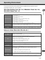
Operating Environment ...................................................................... 1-11
VB Initial Setting Tool Ver. 5.0, VBAdmin Tools Ver. 5.0,
VB-C500 Viewer Ver. 1.0 .......... 1-11
Network Video Recorder VK-Lite v2.1 .......................................................... 1-11
Notes on Operating Environment ....................................................... 1-13
Notes on Use When the [Windows Firewall] Function is Enabled ............... 1-13
Notes on Use with Windows Server 2003/Windows Server 2008 ................ 1-14
Notes on Use with Windows Server 2008 .................................................... 1-16
Notes on Use with Windows Vista ................................................................ 1-18
Name and Function of Each Part ................................................................. 1-19
Optional Items .................................................................................... 1-22
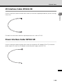
Audio Interface Cable WA500-VB ................................................................ 1-22
I/O Interface Cable WC500-VB .................................................................... 1-23
Power Interface Cable WP500-VB ............................................................... 1-23
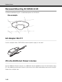
Recessed Mounting Kit SR500-S-VB ........................................................... 1-24
AC Adapter PA-V17 ..................................................................................... 1-24
VK-Lite Additional Viewer License ............................................................... 1-24
Network Video Recorder VK-64/VK-16 v2.1 ................................................. 1-25
v
Contents
Chapter 2
Initial Setting and Installation of Camera
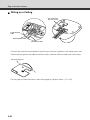
Flow of Setup ....................................................................................... 2-2
Step 1 Install the Software ................................................................... 2-4
Install the Necessary Software ....................................................................... 2-4
Step 2 Connect the Camera to the Network ........................................ 2-6
Connect the Camera to the Network and Turn On the Power ........................ 2-6
Step 3 Perform Initial Setting of the Camera ..................................... 2-10
Perform Initial Setting of the Camera ........................................................... 2-10
Check the Video Captured by the Camera .................................................. 2-13
Step 4 Install the Camera .................................................................. 2-15
Installation Procedure for Direct Mounting on a Ceiling/Wall ....................... 2-16
Installation Procedure for In-Ceiling with a Ceiling/Wall .............................. 2-25
Chapter 3
Appendix
External Dimension Drawing ................................................................ 3-2
VB-C500D ...................................................................................................... 3-2
Recessed Mounting Kit SR500-S-VB (Option) ............................................... 3-2
Main Specifications .............................................................................. 3-3
Input/Output Terminals ........................................................................ 3-5
External Device I/O Terminals ........................................................................ 3-5
Audio Input/Output Terminals ........................................................................ 3-7
vi
Checking of Bundled Items
This product comes with the following items. If any item is missing, contact the store where you
purchased the product.
1. VB-C500D main Unit
4. Setup CD-ROM
2. Safety wire
3. Ceiling mount template
5. Start Guide (This document)
6. Warranty Card (different depending on the region)
Content of Setup CD-ROM
ReadMe-J.txt
: Japanese text covering notes, etc. not included in this document
ReadMe-E.txt
: English text covering notes, etc., not included in this document
Manual
: Folder containing operation manuals (Japanese, English) other than
this document *
VBTools
: Folder containing the installers for other bundled software (two installers
specified below)*
VBToolsInstall.exe : Installer for VB Initial Setting Tool and VBAdmin Tools*
VKLiteInstall.exe
: Installer for Network Video Recorder VK-Lite*
License
: Folder containing licenses for the built-in software of the VB-C500D as well
as bundled software VK-Lite
Sound
: Folder containing sample audio files
* Check our website for the latest versions of bundled software and operation manuals.
vii
Checking of Bundled Items
Operation Manuals
The VB-C500D comes with Start Guide (this document) and Operation Guide included in the
Setup CD-ROM.
Start Guide (This Document)
The safety precautions to be followed when using the VB-C500D, types of bundled
software, operating environment, installation method, initial setting of the camera,
installation method, etc., are explained.
Operation Guide (VBC500DOG_E.pdf)
This document explains the basic setup procedure for the VB-C500D, how to use
VBAdmin Tools and VB-C500 Viewer, troubleshooting, etc. Items that should be
referenced in this document are denoted by "Operation Guide."
Operation Guide is included in the Setup CD-ROM.
Also, a simplified version of recording software VK-Lite ( P. 1-6) is stored in the Setup CD-ROM.
The following operation manuals are available:
Setup Guide (VK21SUG_E.pdf)
This document explains the items to note when using VK-Lite, operating environment,
system configuration, installation method and setup method.
Administrator’s Manual (VK21AM_E.pdf)
This document explains details on how to use VK-Lite. Be sure to read this document.
Viewer Operation Guide (VK21VOG_E.pdf)
This is an operation guide for the VK-Lite viewer. For the detailed operating procedures of
the viewer, refer to Administrator’s Manual.
viii
How to Read This Document
In Start Guide and Operation Guide, screens in Windows Vista are mainly used. Unless otherwise
specified, the same screens apply to Windows XP.
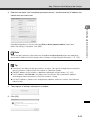
Symbols Used for Safety Precautions
In this document, the following symbols are used to indicate important items the user should
know to use this product safely. Be sure to observe these items.
Symbol
Meaning
Inappropriate handling against the instruction accompanied by this
Warning
symbol may result in death or injury. Be sure to observe this
precaution to use the product safely.
Inappropriate handling against the instruction accompanied by this
Caution
symbol may result in injury. Be sure to observe this precaution to
use the product safely.
Inappropriate handling against the instruction accompanied by this
Note
symbol may result in property damage. Be sure to observe these
precautions.
Note
Tip
This symbol indicates other action or item that requires
attention.
Supplementary information or a reference to the operation is
explained. Users are recommended to read these memos.
ix
Safety Precautions
The following explains the items that must be observed when using the VB-C500D.
If they are not observed, injury, death and/or property damage may occur. Read the following
information carefully and observe the instructions without fail.
Important Warnings
CAUTION
TO REDUCE THE RISK OF ELECTRIC SHOCK, DO NOT REMOVE COVER (OR BACK).
NO USER-SERVICEABLE PARTS INSIDE. REFER SERVICING TO QUALIFIED SERVICE
PERSONNEL.
For optional PA-V17 Users in the UK
When replacing the fuse only a correctly rated approved type should be used and be
sure to re-fit the fuse cover.
The AC adapter can be connected to VB-C500D from a standard AC power outlet.
Please check your instruction manual to make sure that your VB-C500D is compatible
with this adapter.
• The socket-outlet should be installed near the equipment and should be easily
accessible.
• Unplug the equipment from the wall outlet before cleaning or maintaining.
FDA regulation
This Network Camera has not been evaluated by the Food and Drug Administration
(FDA) for use as a medical device. When incorporated into a system with medical
applications, FDA regulations may apply. Therefore, please consult your legal advisor
to determine whether FDA regulations apply.
x
Safety Precautions
FCC NOTICE
Network Camera, Model Name: VB-C500D
This device complies with Part 15 of the FCC Rules. Operation is subject to the
following two conditions: (1) This device may not cause harmful interference, and (2)
this device must accept any interference received, including interference that may
cause undesired operation.
Note: This equipment has been tested and found to comply with the limits for a Class B
digital device, pursuant to Part 15 of the FCC Rules. These limits are designed to
provide reasonable protection against harmful interference in a residential installation.
This equipment generates, uses and can radiate radio frequency energy and, if not
installed and used in accordance with the instructions, may cause harmful interference
to radio communications.
However, there is no guarantee that interference will not occur in a particular
installation. If this equipment does cause harmful interference to radio or television
reception, which can be determined by turning the equipment off and on, the user is
encouraged to try to correct the interference by one or more of the following measures:
• Reorient or relocate the receiving antenna.
• Increase the separation between the equipment and receiver.
• Connect the equipment into an outlet on a circuit different from that to which the
receiver is connected.
• Consult the dealer or an experienced radio/TV technician for help.
Use of shielded cable is required to comply with class B limits in Subpart B of Part 15
of FCC Rules.
Do not make any changes or modifications to the equipment unless otherwise
specified in the manual. If such changes or modifications should be made, you could
be required to stop operation of the equipment.
Canon U.S.A. Inc.
One Canon Plaza, Lake Success, NY 11042, U.S.A.
Tel No. (516) 328-5600
Canadian Radio Interference Regulations
This Class B digital apparatus complies with Canadian ICES-003.
xi
Safety Precautions
Precautions for Installation
Warning
Do not install the product in the following places:
• Place receiving strong direct sunlight, near heat generating objects, or subject
to high temperature
• Place near fire sources or flammable solvents (alcohol, thinner, etc.)
• Humid or dusty place
• Place subject to lamp black or steam
• Place subject to sea wind
• Narrow, sealed place
Fire or electric shock may result.
Note
For installation or inspection of the VB-C500D, consult/request the store where
you purchased the product.
• Wire the VB-C500D power supply, network, or other cables safely and securely
according to the relevant regulations such as technical standards for electrical
installations.
• When installing the VB-C500D, select a ceiling surface, etc., capable of
withstanding the total weight of the camera and all options used (Recessed
Mounting Kit), provide sufficient reinforcements and use the bundled safety
wire if necessary.
• To prevent injuries and equipment damage due to falling items, periodically
check the brackets and screws for rusting and loosening.
• Installation in a place subject to significant vibration is not recommended,
because it may cause the equipment to malfunction.
• Do not install the VB-C500D on an unstable or inclined surface.
• Do not carry the product while the LAN cable or other cables still connected to
it.
Malfunction may occur.
xii
Safety Precautions
Precautions for Use
Warning
• If smoke, abnormal noise, heat, odor or any other abnormality is detected,
immediately stop using the camera and contact your nearest Canon dealer.
Continuing to use the product may result in fire or electric shock.
• Do not disassemble or modify the camera.
• Do not put water or other liquid in the camera or splash or otherwise wet the
camera.
• Do not put foreign objects in the camera.
• Do not use sprays of flammable gases near the camera.
• When the camera is not used for a long period, disconnect the LAN cable,
external power supply and power connector for AC adapter (optional) from the
camera.
Fire or electric shock may result.
Note
• Do not use this camera for medical devices and other systems that affect human
life.
Delayed or missing image transmission may occur depending on the PC and
network environment, and thus high image transmission accuracy cannot be
assured.
Canon will assume no liability for any accident or damage resulting from use of
the VB-C500D in the aforementioned devices or systems.
• Do not capture the sun, halogen lamps and other very bright light sources or
subjects.
• Do not apply impact on the camera.
Malfunction may result.
This installation should be made by a qualified service person and should
confirm to all local codes.
xiii
Safety Precautions
Notes on Use of Motion Detection, Stream for Recording and
Bundled Recording Software VK-Lite
Note
• Avoid using Motion Detection, Stream for Recording or recording software
VK-Lite for surveillance where very high level of reliability is constantly
required.
These are support functions for monitoring. They do not guarantee monitoring with
very high accuracy, however, as they might not work as accurately as expected
under certain conditions. Canon will assume no liability for any accident or
damage resulting from use of these functions.
Precautions for Use of Optional AC Adapter PA-V17
Warning
• Do not use any AC adapter or AC cable other than the dedicated AC adapter or
AC cable.
• Do not put heavy objects on the power cable.
• Do not pull, forcibly bend, scratch or modify the power cable.
• Do not cover or wrap the AC adapter (optional) with a cloth or thick cotton
blanket.
Fire or electric shock may result.
Be sure to read the operation manual for PA-V17 before use.
Notes on Cleaning
Warning
• Do not use alcohol, thinner, benzene or any other flammable solvent.
Fire or electric shock may result.
xiv
Safety Precautions
Maintenance
Turn off the power before cleaning the camera ( P. 2-7).
Cleaning of Exterior
1. Dampen a soft cloth with water or diluted neutral detergent and wipe the soiled areas gently.
2. Wipe with a dry cloth.
Cleaning of Lens
Use a commercial lens cleaner to remove soiling on the lens surface.
Scratches on the lens surface may result in undesirable images.
Maintenance for Dome Case
A soiled dome is a cause of poor image quality, so clean the dome periodically.
1. Remove the dome by referring to "Installation Procedure for Direct Mounting on a Ceiling/
Wall" ( P. 2-16) in Chapter 2, "Initial Setting and Installation of Camera".
2. Dampen a soft cloth with water or diluted neutral detergent and wipe the soiled areas gently.
3. Wipe with a dry cloth.
4. When you are done, install the dome case.
To prevent injuries and equipment damage due to falling items, periodically check the brackets
and screws for rusting and loosening.
For checkups, please contact the dealer where you purchased the product.
Maintenance for Recessed Mounting Kit (Optional)
To prevent injuries and equipment damage due to falling items, periodically check the brackets
and screws for rusting and loosening.
For checkups, please contact the dealer where you purchased the product.
xv
Safety Precautions
xvi
Before Use
The following explains the features of this camera, bundled software,
operating environment, and name and function of each part.
Features of VB-C500D
The VB-C500D is a compact network camera for indoor installation integrating camera and server
features.
Wide-angle Varifocal Lens
Equipped with a wide-angle varifocal lens with a wide angle of 82°, F1.1 and optical 2.4x
zoom (digital 4x), the VB-C500D achieves video monitoring in wide-ranging applications,
including stores and offices, as well as applications in small areas such as at ATM and in
elevator halls.
Compact Design Suitable for Various Installation Environments
The ultra-compact dome camera of 3.7 inches in size (dome diameter) can be installed
inconspicuously in locations where appearance is given priority, such as in condominiums
and hotel stores.
It can be installed in various ways, such as directly mounting on the ceiling, recessed into the
ceiling, and mounting on a wall.
Capturing Color Images at 0.2 Lux
With its high imaging quality, the camera can capture color images at a minimum subject
illumination of 0.2 lux while maintaining low noise and high color repeatability (when the 1/30second Smart Shade Control is turned on).
Digital Night Mode Function to Automatically Adjust to
Capturing at Low Illumination
When the illumination is low, such as during nighttime, the capture mode is automatically
switched from color to monochrome and Canon's unique low-noise, high-quality imaging
technology is used to increase the digital sensitivity. If the Digital Night Mode function is used,
images can be captured at a minimum subject illumination of 0.1 lux (when the 1/30-second
Smart Shade Control is turned on).
Smart Shade Control
When the background is bright and the subject is difficult to see, you can change the contrast
of dark areas to make the subject clearer. Unlike the backlight compensation, blown out of the
background can be prevented because bright areas are not controlled. These processes are
implemented by the dedicated hardware in the camera, so drops in image quality can be
reduced and system load can be decreased compared to when the conventional shade
control is used ( "Setting the Smart Shade Control in "Operation Guide").
PoE
The VB-C500D supports Power over Ethernet (PoE*) technology, which enables simultaneous
video/audio data transmission and power supply by simply connecting a PoE HUB and a
single LAN cable ( P. 2-6). When connecting to a PoE HUB, you need not connect a power
adapter to the camera or perform any power wiring.
* PoE stands for Power over Ethernet, which is compliant with the IEEE 802.3af standard by the Institute of
Electrical and Electronic Engineers.
1-2
Features of VB-C500D
Install-Less VB-C500 Viewer
This camera has a built-in VB-C500 Viewer, so its data can be viewed using a browser.
Accordingly, there is no need to install a PC application. Also, three levels of user privileges
can be set, including [Administrator], [Authorized Users] and [Guest Users].
The camera incorporates DIGIC NET that offers high network distribution performance and a
range of intelligent functions to achieve high image quality and high-speed communication
such as simultaneous distribution of JPEG and MPEG-4.
Simultaneous Distribution of JPEG and MPEG-4
Video compression adopts JPEG/MPEG-4 to achieve high image quality/high frame rate of up
to 30 frames per second*1 in VGA (640x480). Up to 30 clients*2 can view the same image
simultaneously.
*1 Note that the frame rate may drop depending on the performance of the viewer PC, number of clients
connected at the same time, network load, etc.
*2 In MPEG-4, up to 10 clients can be connected at the same time.
Multi-Streaming
In JPEG, image can be distributed in three sizes (640x480, 320x240, 160x120) at the same
time.
High Quality Video of Moving Subjects
The VB-C500D utilizes a progressive-scan CCD to allow for the capture of noise-less, high
quality video of moving subjects.
Selectable Metering Modes for Various Shooting Condition
Image can be captured by switching the metering mode* to one of three options, including
Center-weighted, Average and Spot, according to the shooting condition of the camera. (
"Setting Exposure" in Operation Guide)
* Brightness (light quantity) of the subject is measured to adjust the exposure.
Uploading and Sound Playback by Motion Detection Function
Change in video caused by movement of the subject is detected to upload the refreshed
image and play sound.
Upload, E-mail Notification
Events generated by the motion detection function or an external input device are used as
triggers to upload images tentatively recorded in the camera to the specified location via FTP/
HTTP/SMTP (e-mail), or notify an event via HTTP/SMTP (e-mail).
1-3
Before Use
Canon's Network Video Processor "DIGIC NET"
1
Features of VB-C500D
Two-Way Audio (Full Duplex)
A microphone or speaker with amplifier can be connected*1 to the camera to transmit/receive
audio (full duplex) via the viewer*2. You can select a desired audio input mode from LINE IN
and MIC IN by switching the setting on the setting page ( P. 3-7).
*1 Microphones and amplifiers are sold separately.
*2 VK-Lite Viewer is the only viewer that supports two-way audio communication.
VB-C500 Viewer only supports audio reception.
Small-scale Video Monitoring by Simplified Recording Software
VK-Lite
This product comes with a simplifier version VK-Lite of the optional Network Video
Recorder VK-64/VK-16 v2.1 ( P. 1-6). Video captured by up to four cameras can be
recorded/displayed in real time, to achieve small-scale video monitoring.
1-4
Bundled Software
The VB-C500D comes with the software specified below.
For the latest information on this product (firmware, bundled software, operation manuals,
1
operating environment, etc.), visit our website.
Before Use
VB Initial Setting Tool Ver. 5.0 ( P. 2-10)
VB Initial Setting Tool is for initial setting of the VB-C500D. It is installed from Setup CD-ROM
( P. 2-4). Users other than Administrators need not install this tool.
VBAdmin Tools Ver. 5.0 ( Overview of VBAdmin Tools in Operation
Guide)
VBAdmin Tools are for visually setting motion detection and for displaying logs taken by the
camera. It is installed from Setup CD-ROM ( P. 2-4). Users other than Administrators need not
install this tool.
1-5
Bundled Software
VB-C500 Viewer Ver. 1.0 ( Overview of VB-C500 Viewer in Operation Guide)
VB-C500D Viewer is for displaying video captured by this camera and controlling the camera.
Three users can be set according to the camera control rights, including [Administrator], [Authorized
Users] and [Guest Users]. This tool is already built into the camera and need not be installed
beforehand ( P. 2-4). JPEG video captured by the VB-C500D can be displayed.
To display MPEG-4 video, install VK-Lite Viewer ( P. 1-7).
Note
To use the camera with VBAdmin Tools for the VB-C60, VB-C300 or VB-C50 series, install
VBAdmin Tools for the VB-C50 series first, and then install VB-C300, install VB-C60, and
finally install VBAdmin Tools bundled with the camera.
Tip
VB Initial Setting Tool Ver. 5.0 can be used commonly with the VB-C60, VB-C300 and VB-C50
series.
Network Video Recorder VK-Lite v2.1 ( Setup Guide)
VK-Lite v2.1, which is a simplified version of the optional "Network Video Recorder VK-64/VK-16
v2.1" ( P. 1-25), is included in the package. VK-Lite consists of the following two software
programs:
1-6
Bundled Software
Software Configuration of VK-Lite
Overview
VK-Lite Storage Server
Up to four cameras can be registered to record video.
1
License
Before Use
Type
1 license
Recorded video saved in the storage server can be
VK-Lite Viewer
played or live video (JPEG/MPEG-4) can be displayed as
it is captured by the camera. Up to four cameras can be
1 license
registered for the viewer.
VK-Lite Storage Server and VK-Lite Viewer can also be installed in, and run on, the same PC.
VK-Lite Viewer can also be used independently, without connecting to VK-Lite Storage Server.
Configuration example based on
Configuration example with VK-Lite Viewer only
installation on the same PC
VK-Lite Storage Server
VK-Lite Viewer
VK-Lite Viewer
For VK-Lite, following cameras can also be registered and used.
Supported
cameras
VB-C500D, VB-C60/VB-C60B, VB-C300/VB-C300B
VB-C50i/VB-C50iR, VB-C50FSi, VB-C50Fi
Note
To add a VK-Lite Viewer, you need to purchase an optional "VK-Lite Additional Viewer
License".
1-7
Bundled Software
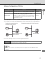
Key Functional Limitations of VK-Lite and VK-64/VK-16
Category
Camera
connection
Key functional limitation
VK-Lite v2.1
VK-64/VK-16 v2.1
4 units
64 units/16 units
Maximum number of
cameras that can be
connected
Recording format
JPEG
JPEG
MPEG-4
Normal schedule
recording (continuous
Normal schedule
Recording mode
Storage
recording (continuous
recording)
Manual recording
server
recording, sensor
event recording,
motion detection
recording)
Special day schedule
recording
Manual recording
Maximum recording frame
rate
Maximum video retain
period
Registration of multiple
storage servers*2
Viewer
5 fps
30 fps*1
12 weeks (90 days)
999 weeks*1
―
Number of displayable
No more than 8 is
video windows
recommended.
Layout Sequences*3
―
Not limited*1
*1 The maximum limit may be imposed depending on the number of cameras, PC performance and hard
disk space, network load, etc.
*2 When multiple storage servers are used, determine one master storage server. This way, cameras
registered for each storage server, recorded data, etc., can be managed centrally using the viewer.
With VK-Lite, switch the storage servers one by one if multiple storage servers are connected to the viewer.
*3 This function allows the displayed viewer window to be switched at specified intervals.
1-8
Bundled Software
Note
For details on the operating methods and function limitations pertaining to VK-Lite, refer to the
Setup Guide and Administrator’s Manual.
Before Use
Tip
With VK-Lite, multiple storage servers cannot be registered. However, this function can be
utilized if the optional VK-64 Viewer is used. Up to 10 units of VK-Lite Storage Server can be
centrally managed and operated.
Comparison of Two Viewers
The VB-C500D has two viewers. The key differences are specified below.
Viewer type
Live video display
VB-C500 Viewer
JPEG
VK-Lite Viewer
JPEG/MPEG-4
Audio
Receive audio from the VB-C500D
(one-way communication)
Transmit/receive audio (two-way
communication)
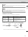
VB-C500 Viewer Audio Reception (One-way Communication)
VB-C500D
Microphone
(sold separately)
1
JPEG
VB-C500 Viewer
Network
Audio
Speaker
Audio from the microphone connected to the VB-C500D can be listened from the viewer speaker.
1-9
Bundled Software
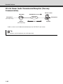
VK-Lite Viewer Audio Transmission/Reception (Two-way
Communication)
VB-C500D
Microphone
(sold separately)
JPEG/MPEG-4
VK-Lite Viewer
Speaker
(sold separately)
Audio
Audio can be transmitted/received between the VB-C500D and viewer.
Tip
PC, speaker and microphone are sold separately.
1-10
Microphone
Network
Speaker
Operating Environment
For the latest information on this product (firmware, bundled software, operation manuals,
operating environment, etc.), visit our website.
OS and browser
Viewer display
Audio
Windows Vista Home Premium/Business/Enterprise/Ultimate (SP1),
Internet Explorer 7.0
Windows Server 2008 Standard
Internet Explorer 7.0
Windows Server 2003 R2 Standard Edition (SP2),
Internet Explorer 6.0 (SP2)/7.0
Windows Server 2003 Standard Edition (SP2),
Internet Explorer 6.0 (SP2)/7.0
Windows XP Professional (SP3), Internet Explorer 6.0 (SP3)/7.0
With VB-C500 Viewer, use of a high-resolution display with an effective display
area of 1024 x 768 or more is recommended.
If the camera's audio feature is used, the PC's audio support feature is required.
Network Video Recorder VK-Lite v2.1
CPU
Pentium 4 2.2 GHz or more
Pentium 4 3.4 GHz or more, if MPEG-4 is used.
Windows Vista Home Premium/Business/Enterprise/Ultimate (SP1)*1
Windows Server 2008 Standard
OS
Windows Server 2003 R2 Standard Edition (SP2)
Windows Server 2003 Standard Edition (SP2)
Windows XP Professional (SP3)
Memory
Hard disk
1 GB or more
Storage server : 20 GB or more (NTFS format)*2
Viewer
: 2 GB or more
High-resolution, 16-bit color display with an effective display area of
1024 x 768 or more
Viewer display
Use a video card of highest possible performance.
If a PCI video card is used, the display performance may drop.
Audio
To use the camera's audio function or enable audio alert for event notification
when the viewer is used, the PC's audio support function is required.
1-11
1
Before Use
VB Initial Setting Tool Ver. 5.0, VBAdmin Tools Ver. 5.0,
VB-C500 Viewer Ver. 1.0
Operating Environment
*1 Windows Vista and Windows Server 2008 support the 32-bit and 64-bit editions. Other OSs support only
the 32-bit edition.
*2 External hard disks cannot be used.
Tip
The optional VK-64/VK-16 v2.1 does not support Windows Vista Home Premium.
1-12
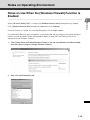
Notes on Operating Environment
Notes on Use When the [Windows Firewall] Function is
Enabled
1
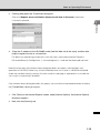
If the [Windows Security Alert] dialog box appeared, click [Unblock].
Once this button is clicked, this warning dialog box will no longer appear.
If the [Windows Security Alert] dialog box is not displayed, the warning function of the Windows
firewall may be disabled. Follow the procedure below to add [VB Initial Setting Tool] as an
exception to the Windows Firewall.
1. Click [Control Panel] and select [Windows Firewall]. If you are using Windows Vista/Server 2008,
also click [Allow a program through Windows Firewall].
2. Next, click the [Exceptions] tab.
1-13
Before Use
When [VB Initial Setting Tool] is started, the [Windows Security Alert] dialog box may appear.
Notes on Operating Environment
3. Click the [Add program…] button to add [VB Initial Setting Tool].
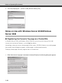
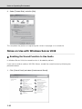
Notes on Use with Windows Server 2003/Windows
Server 2008
Registering the Camera's Top page as a Trusted Site
In Windows Server 2003 and Windows Server 2008, the security level for Internet sites and
intranet sites on Internet Explorer is set to [High] by default.
Accordingly, when you access the top page of the camera, VB-C500 Viewer or any setting page,
the contents block dialog box appears and the page is not displayed correctly.
To display these pages correctly, register them as trusted sites.
1. When the camera's top page is accessed via Internet Explorer, the following dialog box appears.
1-14
Notes on Operating Environment
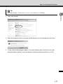
2. Clicking [Add] opens the Trusted sites dialog box.
Clear the [Require server verification (https:) for all sites in this zone] check box,
if currently selected.
1
Before Use
3.
Enter the IP address of the VB-C500D under [Add this Web site to the zone], and then click
[Add] to register the site as a trusted site.
For details on registering trusted sites, click the [Learn more about Internet Explorer’s
Enhanced Security Configuration...] in the dialog box in 1 and see the displayed overview.
Note that even when the contents block dialog box does not appear, setting pages and
operations of VB-C500 Viewer may still be limited because Java script is sometimes disabled
under the standard security setting. Once the camera's top page is registered as a trusted site,
Java script is automatically enabled.
If the contents block dialog box does not appear, you can follow the procedure below to display
the [Trusted Sites] adding dialog box.
1. Click [Tools] on the Internet Explorer screen, select [Internet Options], the [Internet Options]
dialog box appears.
2. Next, click the [Security] tab.
1-15
Notes on Operating Environment
3. Select [Trusted Sites], and click [Site].
This completes the process of registering the camera's top page as a trusted site.
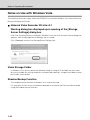
Notes on Use with Windows Server 2008
Enabling the Sound Function to Use Audio
In Windows Server 2008, the sound function is disabled by default.
If you want to receive audio on VB-C500 Viewer, enable the sound function by following the
procedure below.
1. Click [Control Panel] and select [Hardware and Sound].
1-16
Notes on Operating Environment
Tip
If [Control Panel] is displayed in a classic view, double-click [Sound].
Before Use
2.
1
Next, click [Sound].
3. When the dialog box with the message, [Audio Service is not running] appears, click [Yes].
4.
Finally, the [Sound] dialog box appears. Click the [Playback] tab to confirm that an audio
device has been installed. (If no audio device is installed, check the manual for you PC.)
1-17
Notes on Operating Environment
Notes on Use with Windows Vista
The following restrictions apply when the VB-C500D is used with Windows Vista Home Premium/
Business/Enterprise/Ultimate.
Network Video Recorder VK-Lite v2.1
Warning dialog box displayed upon opening of the [Storage
Server Settings] dialog box
If the User Account Control is enabled in Windows Vista, the User Account Control dialog box
appears when the Storage Server Settings tool is started.
Click [Continue] and start the Storage Server Settings tool.
Video Storage Folder
In Windows Vista, do not specify the Windows folder or Program Files folder on the system
drive as the folder for storing snapshots and specified video files. Images and videos cannot
be saved in these folders.
Shadow Backup Function
The shadow backup function of Windows Vista cannot be used.
If a setting file of VK-Lite was accidentally deleted, for example, the file cannot be restored
using the shadow backup function.
1-18
Notes on Operating Environment
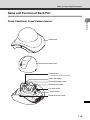
Name and Function of Each Part
1
Before Use
Dome Case/Inner Cover/Camera Interior
Dome case
Inner cover
Varifocal lens
Horizontal field of view 82°
Focus lock screw
Zoom adjustment knob
Rotation lock screw
Pan lock screw
Tilt lock screw
Dome case lock screw
1-19
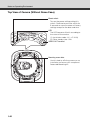
Notes on Operating Environment
Top View of Camera (Without Dome Case)
Reset switch
Turn on the power while pushing this
switch. Continue to push the switch for
5 seconds or more to restore all factory
settings except for the date and time.
LED
The LED becomes lit/unlit according to
the status of the camera.
(1) Installation mode: Lit ( P. 2-23)
(2) Other steady state: Unlit
VIDEO OUT terminal
Mounting screw hole
Use this hole to affix the camera on an
installation surface or affix an optional
Recessed Mounting Kit.
1-20
Notes on Operating Environment
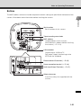
Bottom
The MAC address and serial number required in network setting are specified at the bottom of the
camera. Write down these information before installing the camera.
1
Before Use
Serial number
Serial number of this camera.
Tripod mounting screw holes
MAC address
Unique address of this camera.
Write down this address before installing
the camera ( P. 2-10).
LAN connector
Conforming to 100Base-TX
PoE power supply (conforming to the
IEEE 802.3af standard)
External device I/O terminals ( P. 3-5)
Power connection terminal ( P. 2-9)
Audio Input/Output Terminals ( P. 3-7)
Safety wire screw
Install the safety wire supplied with the
camera.
1-21
Optional Items
Purchase options separately as necessary.
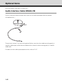
Audio Interface Cable WA500-VB
Use this interface cable to connect the camera to an audio input/output device (speaker,
microphone, etc.).
Marking band
OUT
IN
The terminal marked "1" on the marking band (farther away from the cable branching point) is
used for audio output, while the unmarked terminal (closer to the branching point) is used for
audio input.
For details on the audio input/output terminals, refer to P. 3-7.
1-22
Optional Items
I/O Interface Cable WC500-VB
Use this interface cable to connect the camera to a contact input/output device (sensor, warning
1
Before Use
lamp, etc.).
For details on the external device input/output terminals, refer to P. 3-5.
Power Interface Cable WP500-VB
Use this interface cable to connect the camera to an optional AC adapter (PA-V17) or external
power supply. For use of an AC adapter or external power supply, refer to P. 2-9.
1-23
Optional Items
Recessed Mounting Kit SR500-S-VB
The Recessed Mounting Kit is a dedicated option for VB-C500D.
Use example
AC Adapter PA-V17
Use this adapter when a PoE HUB or external power supply is not used.
VK-Lite Additional Viewer License
VK-Lite Additional Viewer License is an additional license needed to install VK-Lite Viewer to each
PC. You need to purchase the license if you want to view video captured by the camera using VK
Viewer from multiple sites.
1-24
Optional Items
Network Video Recorder VK-64/VK-16 v2.1
1
High-functional monitoring & recording software that achieves simultaneous monitoring of
Before Use
multiple sites.
Example of VK-64/VK-16 Viewer screen
Note
VB-C500D cannot be used with an old version of VK-64/VK-16. If you are using an old version,
update it to the new version. For details, visit our website.
Tip
This camera comes with VK-Lite v2.1, which is a simplified version of VK-64/VK-16 v2.1
( P. 1-6). Up to four cameras can be registered and used.
1-25
Optional Items
1-26
Initial Setting and
Installation of Camera
The following explains how to install the camera.
First, install the necessary software from the bundled Setup CD-ROM.
Next, connect the camera to the network and perform initial setting
of the camera. Check the video using VB-C500 Viewer, and then
install the camera.
Before installing the camera,
be sure to set the IP address.
Flow of Setup
Step 1
Install the software
Insert the bundled Setup CD-ROM in the PC and install the necessary software ( P. 2-4).
PC
Bundled Setup CD-ROM
Step 2
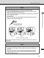
Connect the camera to the network
Connect the VB-C500D and PC to the network ( P. 2-6).
If a PoE HUB or Midspan is used, consult your Canon sales representative.
VB-C500D
LAN cable
PC
PoE HUB
The figure shows connection via a PoE HUB.
2-2
Flow of Setup
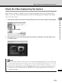
Step 3
Perform initial setting of the camera
Start VB Initial Setting Tool and perform initial setting of the camera ( P. 2-10).
Check the image using VB-C500 Viewer ( P. 2-13).
Step 4
Initial Setting and Installation of Camera
VB Initial Setting Tool window
VB-C500 Viewer
Install the camera
Install the VB-C500D securely ( P. 2-15).
2-3
Step 1 Install the Software
Install the Necessary Software
First, install the necessary software from the bundled Setup CD-ROM ( P. 1-5).
Software for Initial Setting and Management of the Camera
Type
VB Initial Setting
Tool
Overview
This tool is used to perform initial setting of the camera ( P. 2-10).
Users other than Administrators need not install this tool.
This tool is used to manage the camera ( Chapter 2 in Operation
VBAdmin Tools
Guide).
Users other than Administrators need not install this tool.
D Install it by executing VBToolsInstall.exe in the VBTools folder of Setup CD-ROM.
Recording Software
Type
Network Video
Recorder VK-Lite
Overview
This software is used to display and record video captured by the
camera. It consists of two components, Storage Server and Viewer
( P. 1-6).
D Install it by executing VKLiteInstall.exe in the VBTools folder of Setup CD-ROM.
Note
Use VK-Lite Viewer if you want to display MPEG-4 video from the camera.
Only JPEG video can be displayed using the built-in VB-C500 Viewer.
In-Camera Software (Need Not be Installed)
Type
Overview
This software is used to display video captured by the camera. The
VB-C500 Viewer
software is already built into the camera and need not be installed
beforehand ( P. 1-6).
2-4
Step 1 Install the Software
At this time, be sure to install VB Initial Setting Tool required in initial setting of the camera.
1. Insert Setup CD-ROM bundled with the camera in the CD-ROM drive of the PC, and perform
the following procedure.
(1) After confirming that all other applications have been closed, click the [Start] menu and
then select [My Computer].
Initial Setting and Installation of Camera
(2) Double-click the displayed CD-ROM icon VBTools Folder and then click
VBToolsInstall.exe.
2. When the initial screen appears, select the installation method to install the software.
Easy Installation
: VB Initial Setting Tool and VBAdmin Tools are installed.
Custom Installation
: The user can select and install desired software.
3. When the installation is complete, an icon appears on the desktop.
This completes the installation.
2-5
Step 2 Connect the Camera to the Network
Connect the Camera to the Network and Turn On the Power
Here, an example of connecting one camera to a PC via a HUB is explained.
VB-C500D comes with a PoE (Power over Ethernet). The power can be supplied to the camera,
via a LAN cable, from a PoE HUB conforming to IEEE 802.3af.
Via PoE HUB
LAN cable
(Back)
PoE HUB
Notebook PC
AC power cable
If an AC adapter (optional) or external power supply is used, connect it as shown below.
For details on the connection method, refer to P. 2-9.
Via AC adapter or external power supply
Power interface cable
AC adapter
AC power
cable
LAN cable
(Back)
HUB
Notebook PC
The figure shows an AC adapter (optional).
2-6
Step 2 Connect the Camera to the Network
Tip
When connecting an AC adapter (optional), unplug the connector at the end of the output
cable for AC adapter and connect the wires to the power interface cable.
The power interface cable can be connected with no polarity.
If the power is supplied by the PoE via a LAN cable on the VB-C500D, disconnect and connect
the LAN cable to the HUB receiving the power, to turn the power "ON"/"OFF."
If an AC adapter (optional) or external power supply is used, disconnect and connect the power
plug of the AC adapter (optional) or external power supply, to turn the power "ON"/"OFF."
Note
z For details on PoE HUB and Midspan, check with your Canon sales representative.
z For the operating methods and other details of a PoE HUB or Midspan, see the operation
manual or other documentation that comes with the applicable device.
z For the LAN cable connecting the camera and a PoE HUB, use a cable of Category 5 or
higher of a length not more than 100 m.
z If the camera is connected to a switching HUB, changing the connection while the camera
is operating may disable communication due to the learning function of the HUB. Do not
change the connection while the camera is operating.
z An AC adapter (optional) can also be connected to the camera while the power is supplied
from a PoE HUB. In this case, the PoE power is given priority while the power is supplied
from the PoE HUB and the power from the AC adapter (optional) is not used. Once the PoE
power is cut off, the power is automatically supplied from the AC adapter (optional).
VB-C500D
PoE HUB
LAN cable
Max. 100m (328.1 ft)
HUB
LAN cable
VB-C500D
Midspan
(LAN cable power supply device)
* Midspan (LAN-cable power supply) is a device that supplies power to the camera via a LAN cable,
just like a PoE HUB.
2-7
Initial Setting and Installation of Camera
This camera has no power switch.
Step 2 Connect the Camera to the Network
Note
When turning off the power and then turning it back on, wait for at least 5
seconds before turning on the power. If the power is turned on too quickly, the
camera may not operate correctly. Also, when disconnecting/connecting the
power connection, be sure to observe the instructions provided in "Safety
Precautions/Notes on AC Adapter (Optional)" ( P. xiv).
• The current may be limited for each port depending on the PoE HUB used.
However, the camera may not operate correctly when the current is limited. If
the camera malfunctions, do not limit the current.
• The total current consumption of ports may be limited depending on the PoE
HUB used. If multiple ports are used, the ports may not operate correctly.
Check the operation manual for the PoE HUB you are using.
2-8
Step 2 Connect the Camera to the Network
Use of External Power Supply
Connect the bundled power interface cable (WP500-VB) as shown below.
Screwdriver
Tightening torque:
0.4N·m (3.54lbf·in) (max.)
Initial Setting and Installation of Camera
Stripping length
Power interface cable
Approx. 5 mm (0.20 in)
AC adapter
Use a 12-VDC or 24-VAC power supply insulated from 100 VAC.·
12 VDC can be connected in a non-polar condition.
Use the power supply within the following voltage range.
24 VAC:
Voltage fluctuation within 24 VAC±10%
(50 or 60 Hz within ± 0.5 Hz)
Current supply capacity per camera 0.23 A
12 VDC:
Voltage fluctuation within 12 VDC±10%
Current supply capacity per camera 0.36 A
* If a 12-VDC battery power supply is used, be sure to connect a resistor of 0.5 to 1.0Ω/20 W
or more to the power line.
Applicable wires and recommended power cable length
#18
#16
(single wire Φ1.0 mm
(single wire Φ1.3mm
(Φ0.0039 in), stranded wire
(Φ0.051 in), stranded wire
Φ1.2 mm (Φ0.0047 in))
Φ1.6mm (Φ0.063 in))
Maximum cable length, 12 VDC (m (ft))
23 (75.5)
32 (105.0)
Maximum cable length, 24 VAC (m (ft))
46 (150.9)
64 (210.0)
Applicable cable (AWG)
Conductor size (Φmm, Φinch)
Use a UL cable (UL-1015 or equivalent) for wiring 12 VDC or 24 VAC.
This completes the network connection.
2-9
Step 3 Perform Initial Setting of the Camera
Perform Initial Setting of the Camera
Set the network for the VB-C500D using VB Initial Setting Tool.
1. Launches VB Initial Setting Tool.
Double-click the [VB Initial Setting Tool v5.0] icon on the desktop, or click the [Start] menu,
click [Programs], click [Webview Livescope], and then select [VB Initial Setting Tool v5.0].
Double-click the icon on the desktop.
2. VB Initial Setting Tool automatically detects the camera connected to the network, and
displays the MAC address, IP address and model name of the camera.
Click to select.
The IP address has been set to
192.168.100.1
at the factory. The MAC address is specified on the label attached to the bottom of the
camera ( P. 1-21).
Note that VB Initial Setting Tool cannot exceed the subnet mask.
Click to select the MAC address, and then click the [Initial setting] button.
2-10
Step 3 Perform Initial Setting of the Camera
3. Enter the user name "root" and default password "camera," and then enter the IP address and
subnet mask you want to set.
Note
There may be cautionary information that should be heeded depending on your operating
environment. Before the initial setting, refer to "Notes on Operating Environment" ( P. 1-13).
Tip
The factory-set Administrator password is "camera." Be sure to change the password for
security reasons ("Administrator Password" in Operation Guide).
The MAC address of this camera is specified at the bottom of the camera ( P. 1-21).
The IP address 192.168.100.1 has been set at the factory. Set a desired IP address
according to the environment in which the camera is used.
For the IP address, subnet mask and gateway address to be set, contact your Network
Administrator.
4. The progress of setting is displayed in a window.
5. Click [OK].
2-11
Initial Setting and Installation of Camera
If the default gateway is not set, clear the [Enter a default gateway address] check box.
When the setting is complete, click [OK].
Step 3 Perform Initial Setting of the Camera
Note
To set the IP address from the DHCP server, set an address from VB Initial Setting Tool to
enable communication with the setup PC and change the setting of [IP Address Setting]
under [Network] ("LAN" in Operation Guide) on the Setting page to [Auto (DHCP)].
The camera will stop issuing IP address assignment requests in 20 minutes after its power
is turned on, upon which detection by VB Initial Setting Tool will be disabled. In this case,
turn on the camera again.
To restore the factory settings, see "Restore Settings" in Operation Guide.
This completes the initial setting.
2-12
Step 3 Perform Initial Setting of the Camera
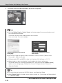
Check the Video Captured by the Camera
When the initial setting is complete, check the video captured by the camera using VB-C500
Viewer. At this time, set the network options on the PC according to the IP address and subnet
mask set in the camera.
Click to select.
2. The web browser starts and the top page of the camera is displayed. Click [VB Viewer] from
[VB-C500 Viewer].
Note
There may be cautionary information that should be heeded depending on your operating
environment. Before the initial setting, refer to "Notes on Operating Environment" ( P. 1-13).
To open the setting page using the [Settings] button, do not change the HTTP port of the
camera from 80. For information on setting the HTTP port number, see "HTTP Server" in
Operation Guide.
2-13
Initial Setting and Installation of Camera
1. Click the MAC address of the camera whose operation you want to check, and then click [Settings].
Step 3 Perform Initial Setting of the Camera
3. The viewer starts and video captured by the camera is displayed.
Note
Clicking [Setting Page] or [Admin Viewer] on the top page of the camera displays each
user authentication window.
The factory-set user name and password are as follows:
User name: root Password: camera
Authentication Window Accessed via
Setting Page
Authentication Window Accessed via
Admin Viewer
Be sure to change the administrator password for security reasons ("Administrator
Password" in Operation Guide).
To display both JPEG and MPEG-4 video, install and use VK-Lite Viewer ( P. 1-7).
Where video can be transmitted to is not limited by the factory settings, etc.
To use the camera for surveillance purposes, etc., be sure to set the [Access Control]
options on the setting page. ("Setting User Access Privileges (Access Control)" in
Operation Guide).
Tip
For information on how to use VB-C500 Viewer, see Operation Guide.
When [Setting Page] is clicked, various options can be set. ("Accessing the Setting Menu"
in Operation Guide).
This completes the video check process.
2-14
Step 4 Install the Camera
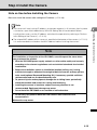
Note on Use before Installing the Camera
Be sure to install the camera after setting the IP address ( P. 2-10).
Note
The camera will stop issuing IP address assignment requests in 20 minutes after its power
installing the camera, set the IP address and check the operation by referring to "Perform
Initial Setting of the Camera" ( P. 2-10).
The unique MAC address of this camera is specified at the bottom of the camera ( P. 1-21).
It is recommended to write down the MAC address before installing the camera.
Note
For installation or inspection of the VB-C500D, consult/request the store where
you purchased the product.
• Wire the VB-C500D power supply, network, or other cables safely and securely
according to the relevant regulations such as technical standards for electrical
installations.
• Before the installation, select an installation location (ceiling, etc.) having
sufficient strength to withstand the weight of both the camera and any options
to be used (optional Recessed Mounting Kit). If necessary, provide sufficient
reinforcement and use the bundled safety wire.
• To prevent injuries and equipment damage due to falling items, periodically
check the brackets and screws for rusting and loosening.
• Installing the camera in locations subject to strong vibration is not
recommended. Equipment damage may occur.
• Do not install the VB-C500D on an unstable or inclined surface.
• Do not carry the product while the LAN cable or other cables are still
connected to it.
Malfunction may occur.
2-15
Initial Setting and Installation of Camera
is turned on, upon which detection by VB Initial Setting Tool will be disabled. Before
Step 4 Install the Camera
Installation Procedure for Direct Mounting on a Ceiling/Wall
Side View of mounting
Roof space
Audio interface cable
Safety Wire
Fix to an anchor or
structure
Connect to a microphone
Connect to a speaker
I/O interface cable
Connect to an external device
Power interface cable
Connect to an AC adapter or
external power supply
Connect to the network
LAN cable
Ceiling board
VB-C500D
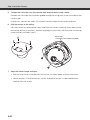
1. Use the bundled template to determine the installation position of the camera.
Confirm the capturing direction of the camera and determine the positions of camera
mounting screws, as well as wiring holes if necessary, using the supplied template.
64.0mm (2.52 in)
Screw holes for
M4.0 screws
Screw holes for
M4.0 screws
2-16
Step 4 Install the Camera
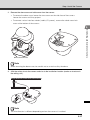
2. Remove the dome case and cable cover from the camera.
• To remove the dome case, loosen the two screws on the side face of the camera.
Loosen the screws until they project.
• To connect various interface cables (audio, I/O, power), remove the cable cover lock
screw at the bottom of the camera.
Initial Setting and Installation of Camera
Dome case lock screw
Note
When removing the dome case, be careful not to scratch or dirty the dome.
3. Affix the safety wire to the camera and also to the installation location (anchor or structure in
the ceiling, etc.).
Note
The wire direction is different depending on how the camera is installed.
2-17
Step 4 Install the Camera
4. Connect each interface cable.
• This process is not required if you don't use any microphone, sensor, AC adapter or
external power supply.
• Select an appropriate interface cable according to the external device used, and
connect the cable to the camera.
• The interface cables and camera have dedicated connectors and connection
terminals, respectively.
• You can select a desired direction from which to take out the interface cables and
other wirings.
Concealing the Wiring in a Ceiling
I/O interface cable
Audio interface cable
Power interface
cable
The cable cover has a cutout groove for guiding interface cables.
Cut out the groove, guide the cables through the cutout, and affix the cover to the camera
with screws.
Cut out the groove.
2-18
Step 4 Install the Camera
Note
Observe the following items when connecting the interface cables.
• Firmly insert the dedicated terminals on the audio interface cable into the
audio input/output terminals on the camera.
Affixing groove for cable
Power
Affixing groove for cable
Initial Setting and Installation of Camera
• Affix each interface cable in the specified groove, as shown below.
Affixing groove for cable
Audio
I/O
Interface cable fixing method
If the cable is not properly installed, it may come off and cause the camera to
malfunction.
2-19
Step 4 Install the Camera
Wiring on a Ceiling
Cut out the side
face of the cover.
Power interface
cable
Audio interface cable
I/O interface cable
If the wirings cannot be concealed in the ceiling, cut out the V-groove in the cable cover and
take out the wirings from the side face of the camera, and then affix the cable cover with screws.
Cut out the V-groove.
For the types of interface cables, refer to the page on Optional Items ( P. 1-22).
2-20
Step 4 Install the Camera
Note
Observe the following items when connecting the interface cables.
• Firmly insert the dedicated terminals on the audio interface cable into the
audio input/output terminals on the camera.
Affix the interface cables in the specified grooves, respectively, in the order of
Initial Setting and Installation of Camera
•
power supply, audio and I/O,
as shown below.
At this time, make sure the heat-shrinkable tubes that protect the cables rest
properly in front of the affixing grooves.
Heat-shrinkable tube
for cable protection
Affixing groove for cable
Power
Affixing groove for cable
Audio
Affixing groove for cable
I/O
Interface cable fixing method
If the cable is not properly installed, it may come off and cause the camera to
malfunction.
Note
• When disconnecting/connecting the audio interface cable,
I/O interface cable and power interface cable, always do so by holding the
connector.
• If the audio input/output, external device input/output and external power
supply are used, do not use any cable other than the dedicated interface
cables. Damage may occur.
2-21
Step 4 Install the Camera
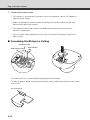
5. Connect the LAN cable, and also connect each external device using a cable.
Connect the LAN cable that has been guided through the wiring hole, to the LAN cable on the
camera side.
If necessary, connect the audio, I/O or power interface cable to each external device.
6. Affix the camera on the ceiling.
Affix the camera by removing the safety sheet from the camera mounting screw holes on the
base of the device (4 locations), and then aligning the screw holes with the camera mounting
screw locations marked in step 1.
Screw holes
(4 locations, Φ4.6 mm(Φ0.18 in), M4.0)
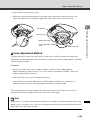
7. Adjust the camera angle and focus.
• Push the inner cover in the direction of the arrow, as shown below, to remove the cover.
• Loosen the pan, tilt and rotation lock screws and adjust the lens in a desired direction,
and then lock the screws.
2-22
Step 4 Install the Camera
• Next, loosen the focus lock screw.
• Adjust the viewing angle and focus using the zoom adjustment knob and focus ring.
When the adjustment is complete, tighten the focus lock screw to lock the focus.
Pan lock screw
Rotation lock screw
Zoom adjustment
knob
Focus lock screw
Focus Adjustment Method
To adjust the focus, press the reset switch to enter the installation mode. Accurate focus
adjustment can be performed in the installation mode. Also note that video output is enabled
in the installation mode.
Procedure
• So you can check the camera image, connect a monitor to the video output or
otherwise display image on the PC via a LAN. (Refer to the page on "Step 3: Check the
video captured by the camera.")
• Next, press the reset switch and adjust the focus.
• Once the focus has been adjusted, turn off the power and then turn it back on, or
reboot the camera from the setting page, to end the installation mode.
Take note that the installation mode ends automatically after 30 minutes. If you want to
continue with the focus adjustment, press the reset switch again.
Note
When the lens is used in the telephoto mode, focus change may become conspicuous if the
dome case is installed. In this case, you can prevent out-of-focus by adjusting the focus to a
point closer than the target subject.
2-23
Initial Setting and Installation of Camera
Tilt lock screw
Step 4 Install the Camera
Tip
Image from the network is disconnected when you switch to the installation mode (when the
reset switch is pressed) or return to a normal mode from the installation mode.
In the installation mode, the camera cannot be controlled.
Only NTSC is supported for video output.
The LED remains lit in the installation mode, and a white square is shown on the bottom left
of the screen.
8. Install the inner cover and dome case.
Finally, place the inner cover and dome case, and tighten the two screws on the side face.
2-24
Step 4 Install the Camera
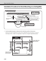
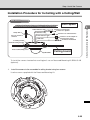
Installation Procedure for In-Ceiling with a Ceiling/Wall
Side View of mounting
Roof space
Fix to an anchor or
structure
Connect to a microphone
Connect to a speaker
I/O interface cable
Initial Setting and Installation of Camera
Audio interface cable
Safety Wire
Connect to an external device
Power interface cable
Connect to an AC adapter or
external power supply
Connect to the network
LAN cable
In-Ceiling bracket
Backside ceiling bracket
Recessed Mounting Cover
VB-C500D
Ceiling board
To install the camera inserted into a ceiling/wall, use an Recessed Mounting Kit SR500-S-VB
(optional).
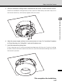
1.
Install the camera to the assembled in-ceiling bracket using four screws.
Use the screws supplied with the Recessed Mounting Kit.
2-25
Step 4 Install the Camera
2. Use the template supplied with the Recessed Mounting Kit to determine the installation
position of the camera.
Confirm the capturing direction of the camera, and then use the supplied template to open
holes for the Backside Ceiling Bracket and in-ceiling bracket.
3. Install the assembled in-ceiling bracket at the back of the ceiling/wall and secure it with screws.
4. Connect the Safety Wire, necessary interface cables and LAN cable, and also connect each
external device with a cable, by following steps 2 to 6 of "Installation Procedure for Direct
Mounting on a Ceiling/Wall."
2-26
Step 4 Install the Camera
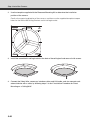
5. Affix the assembled in-ceiling bracket assembled with the camera, on the installation surface.
Hook the assembled in-ceiling bracket on the screws that were loosely secured in step 3, turn
the bracket clockwise, and securely tighten (affix) the screws.
Initial Setting and Installation of Camera
6. Adjust the camera angle and focus in the same manner as in step 7 of "Installation Procedure
for Direct Mounting on a Ceiling/Wall," and install the dome case.
7. Install the recessed mounting cover.
Finally, align the mark (c) on the recessed mounting cover with the mark (I) on the in-ceiling
bracket, and turn the cover clockwise to the mark (I) on the recessed mounting cover to affix
the bracket in position.
This completes the installation.
2-27
Step 4 Install the Camera
2-28
Appendix
This section explains the external dimensions, specifications,
external device input/output terminals, audio input/output
terminals, etc.
External Dimension Drawing
64mm (2.52 in)
136mm (5.35 in)
95mm ( 3.74 in)
VB-C500D
4- 4.6mm
(0.16- 0.18 in)
108mm (4.25 in)
110mm (4.33 in)
148mm (5.83 in)
mm
169
(
utsid
):O
5 in
6.6
27mm
(1.06 in)
63mm
(2.48 in)
Recessed Mounting Kit SR500-S-VB (Option)
n)
4i
r
ete
iam
ed
3- 5.0mm
(0.12- 0.20 in)
m
0°
4m
112mm (4.41 in)
64mm (2.52 in)
19
120°
98mm
(3.86 in)
215mm (8.46 in)
12
8-M4.0mm
(0.31-M0.16 in)
76mm (2.99 in)
110mm (4.33 in)
3-2
(
7.6
Main Specifications
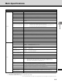
VB-C500D
Image sensor
1/4-inch CCD (primary color filter)
Number of pixels
Effective pixels: 310,000 pixels
Scanning method
Progressive method
Lens
Varifocal lens: Optical 2.4x zoom lens (digital 4x)
Focus length
f=2.6 to 6.2mm
F-value
F1.1 (W end) to F1.4 (T end)
Viewing angle
Horizontal field of view: 82° (W end) to 34° (T end) Vertical viewing angle: 60.5° (W end) to 25.5°
(T end)
Day/night capability
Auto/manual switching
Day mode
: 0.2 lux (F1.1, color, 1/30 second, Smart Shade Control: ON / level 7)
*0.5 lux when the Smart Shade Control is turned off
: 0.1 lux (F1.1, black & white, 1/30 second, Smart Shade Control: ON / level 7)
*0.2 lux when the Smart Shade Control is turned off
Night mode
Camera
Focus
Server
Manual
Focus range
0.7 m (2.3 ft) proximity to ~∞ * Common to Day/Night modes
Shutter speed
1/1 to 1/8000 second
AE
Auto, flickerless, shutter speed (12 levels from 1/8 to 1/8000 seconds)
White balance
Auto/light source/lock (one-shot WB)
Metering mode
Selectable from 3 modes (Center-weighted/Average /Spot)
Exposure compensation
7 levels
Smart Shade Control
7 levels (Function to control dark areas when the video has brightness difference)
Pan angle range
350° (±175°)
Tilt angle range
150° (±75°)
Rotation angle range
350°
Video compression method
JPEG/MPEG-4 Simultaneous data distribution is possible.
Video size
JPEG
MPEG-4
: 640x480/320x240/160x120 (Images of 3 sizes can be distributed simultaneously)
: 640x480/320x240 (Fixed to 1 size)
Video quality
JPEG/MPEG-4: 5 levels (With JPEG, a desired level can be set for each size.)
Frame rate
JPEG
MPEG-4
: 30 to 0.1 fps
: 30/15/10 fps
Maximum frame rate
JPEG
MPEG-4
: Max. 30 fps (640x480)*1
: Max. 30 fps (640x480)*1
Number of clients that can be
connected simultaneously
Up to 30 clients (MPEG-4: Up to 10 clients)
Audio compression method
G.711μ-law (64 kbps)
Audio communication mode
Full duplex (two-way communication)
Audio playback
Protocol
Appendix
Minimum subject illumination
(Audio files can be played on occurrence of events by motion detection or external device input)*2
IPv4 : TCP/IP, UDP, HTTP, FTP, SNMP (MIB2), SMTP (client), DHCP (client), DNS (client), ARP,
ICMP, POP3, NTP, SMTP authentication, WV-HTTP (Canon's original protocol)
IPv6 : TCP/IP, UDP, HTTP, FTP, SMTP (client), DNS (client), ICMPv6, POP3, NDP, SMTP
authentication, WV-HTTP (Canon's original protocol)
IPsec
Camera control
3 types of users (Administrator/Authorized Users/Guest Users) can be controlled/managed separately.
User names and passwords for up to 50 users can be registered.
Connection restriction
Access restriction (user name and password)/IP address restriction (IPv4)/
Restriction on number of clients that can be connected simultaneously
Motion Detection
(Up to four detection areas can be set in the shooting window.)
JPEG image upload
FTP/HTTP/SMTP (e-mail)
Temporary camera memory for upload: Approx. 4 MB max., Frame rate: 10 fps max.
Event notification function
HTTP/SMTP (e-mail)
*1 Note that the frame rate may drop depending on the performance of the viewer PC, number of clients connected at the
same time, network load, etc.
*2 An optional speaker with amplifier is required to play audio.
The specifications are subject to change without notice for purposes of improvement, etc.
3-3
Main Specifications
VB-C500D (Continued)
Network terminal
LAN-1 (RJ45, 100Base-TX (Auto/Full Duplex/Half Duplex))
Audio input terminal
(Used as both LINE IN
and MIC IN)
Φ3.5 monaural mini jack connector
* Connection via an audio interface cable
LINE IN-1 (connected to a microphone with amplifier) or MIC IN-1 (connected to a microphone
without amplifier)
(LINE IN and MIC IN can be switched on the setting page)
Audio output terminal
(LINE OUT)
Φ3.5 monaural mini jack connector
* Connection via an audio interface cable
LINE OUT-1 (connected to a speaker with amplifier)
External device input/output
terminals
Input-2 Output-2
Operating environment
Temperature: -10 to 50°C
Power supply
PoE: Supporting PoE power supply via a LAN connector (conforming to the IEEE 802.3af standard)
Dedicated AC adapter: Supporting optional PA-V17 (100 VAC)
* Connection via a power interface cable (non-polar)
External power supply: Supporting 24 VAC/12 VDC
* Connection via a power interface cable (non-polar)
Power consumption
When PoE is used: approx. 3.3 W max.
Dedicated AC adapter PA-V17 used: approx. 3.6 W max.
Dimensions
136mm x 148mm x 108mm (5.35 in x 5.83 in x 4.25 in) (W x D x H)
Weight
Approx. 640 g (1.411 lb)
Interface
Others
* Connection via an I/O interface cable
Humidity: 20 to 85% RH (non-condensing)
AC adapter (option)
Model
PA-V17
Input
100 VAC, 50/60 Hz
Output
13 VDC, 1.8 A (max.), temperature -10°C to 35°C, humidity 20 to 85% RH (non-condensing)
When combined with the network camera
13 VDC, 1.0A (max.), temperature -10°C to 45°C, humidity 20 to 85% RH (non-condensing)
Polarity
Black line side (-), white line side (+)
Dimensions
58 mm x 118 mm x 25 mm (2.28 in x 4.65 in x 0.98 in) (W x D x H) (excluding projections)
Weight
Approx. 215 g (0.474 lb) (excluding cables)
Model
SR500-S-VB
Recessed Mounting Kit (option)
Type
Silver
Use environment when
combined with the camera
Temperature -10 to 50°C, humidity 20 to 80% RH (non-condensing)
Dimensions
Φ215mm x 63mm (H) (Φ8.46 in x 2.48 in (H)) (including brackets)
Weight
Approx. 395 g (0.871 lb) (including Recessed Mounting Cover and brackets) * Cover only: Approx. 66 g (0.146 lb)
The specifications are subject to change without notice for purposes of improvement, etc.
3-4
Input/Output Terminals
The various input/output terminals of the camera are located inside the cable cover at the bottom
of the camera.
To connect the camera to an audio input/output device, contact input/output device, AC adapter
or external power supply, open the cable cover and connect the device using a dedicated
interface cable. All interface cables come with dedicated terminals for connection with the camera.
Check the shape of each terminal thoroughly and insert the terminal in the correct direction.
Power connection
terminal
Audio input/output
terminals
External Device I/O Terminals
Two external device input terminals and two external device output terminals are available.
VB-C500 Viewer and VK-Lite Viewer can be used to check the conditions of external device
inputs and operate external device outputs. ("Operating the External Device Outputs" and
"Displaying the External Device Input Status" in Operation Guide).
To connect the camera to an external device, use a dedicated I/O interface cable WC500-VB.
(P. 1-23)
The table below lists the colors and functions of spare wires in the I/O interface cable.
Black
Brown
Red
Orange
Yellow
Green
Blue
White
3-5
Appendix
External device
I/O terminals
Input/Output Terminals
Color of spare
wire
Type of corresponding
terminal
Color of spare
wire
Type of corresponding
terminal
1
Black
OUT2_B
5
Yellow
IN2_-
2
Brown
OUT2_A
6
Green
IN2_+
3
Red
OUT1_B
7
Blue
IN1_-
4
Orange
OUT1_A
8
White
IN1_+
External Device Input Terminals (IN1, IN2)
There are two sets of external device input terminals (IN1, IN2), where each set consists of two
terminals. The - terminals are connected to the GND in the camera. Two-wire cables are
connected to the + and - terminals to achieve electrical continuity or insulation between the two
terminals for notification to the viewer.
Note
For the sensors and switches to be connected, connect terminals that are electrically isolated
from each power supply or GND.
External Device Output Terminals (OUT1, OUT2)
There are two sets of external device output terminals (OUT1, OUT2), where each set consists of
two terminals. Each terminal set has no polarity. The condition between the two terminals can be
switched between connected and disconnected by controlling from the viewer. The output
terminals are isolated from the internal circuits of the camera using optical couplers.
The loads connected to the output terminals should be used within the following ratings:
Ratings between output terminals:
Maximum voltage 50 VDC
Continuous load current 100 mA max.
3-6
Input/Output Terminals
Internal Connection Diagram
+3.3V
10kΩ
10kΩ
10kΩ
+
External device
Internal controller
0.1µF
Input terminal:
IN1, IN2
–
Appendix
External
device
Output terminal:
OUT1, OUT2
Tip
Applicable wire for external device cable
Single wire of AWG No. 28 to 22
Conductor size Φ0.32 to 0.65 mm (Φ0.013 to 0.026 in)
Strip the cable by approx. 8 to 9 mm (0.31 to 0.35 in)
Audio Input/Output Terminals
One audio input terminal and one audio output terminal is available.
A microphone, speaker with amplifier or other audio input/output device can be connected to the
camera to send/receive sound via the viewer.
To connect the camera to an audio input/output device, use a dedicated audio interface cable
WA500-VB.(P. 1-22)
Use a Φ3.5 monaural mini jack connector to connect the audio interface cable and audio input/
output device.
Audio Input, Used as Both LINE IN and MIC IN (Monaural Input)
Connects the camera to a microphone. As for audio input of this camera, two types of
microphones, LINE IN and MIC IN types, are supported. Note that the camera only has one audio
3-7
Input/Output Terminals
input. Switch the input mode on the Setting page ("Audio Input" in Operation Guide). The factory
setting is LINE IN.
When LINE IN is selected, a microphone with amplifier can be connected.
When MIC IN is selected, a dynamic microphone or capacitor microphone can be connected.
Input terminal: Φ3.5-mm mini jack (monaural)
• Dynamic MIC IN setting
Input impedance: 1.75 kΩ± 20%
* Supported microphone
Output impedance: 400Ω ~ 600Ω
• Capacitor MIC IN setting
Input impedance (microphone bias resistance): 2.2 kΩ± 20%
Microphone power supply: Plug-in power (voltage: 1.8 V) method
*Supported microphone
Capacitor microphone of plug-in power type
• LINE IN setting
Input level: 1 Vp-p max.
* Use a microphone with amplifier.
Audio Output Terminal LINE OUT (Monaural Output)
Connects the camera to an amplifier with speaker. Audio can be sent from VK-Lite Viewer to a
speaker. Only the administrator can access this terminal.
Output terminal: Φ3.5-mm mini jack (monaural)
• Output level: 1 Vp-p max.
* Use a speaker with amplifier.
3-8
Input/Output Terminals
Note
Switch the LINE IN/MIC IN setting on the Setting page according to the microphone
specification ("Audio Input" in Operation Guide).
If a wrong input is used, the camera or microphone may be damaged. Be sure to set the
correct input.
The volume, sound quality, etc., may change depending on the characteristics of the
microphone used.
To send audio to speaker, use VK-Lite Viewer. Audio cannot be sent from VB-C500 Viewer
Video and audio may sometimes lose synchronism.
Audio may be interrupted depending on the performance of the PC used or the network
environment.
Video and audio can be transmitted to a maximum of 30 clients. If there are too many
clients, audio may be interrupted.
If anti-virus software is used, audio may be interrupted.
Disconnecting/connecting the LAN cable interrupts the audio. Accordingly, reconnect the
LAN connection on the viewer side.
3-9
Appendix
( P. 1-9).
CANON INC.
30-2, Shimomaruko 3-chome, Ohta-ku, Tokyo 1468501, Japan
CANON EUROPA N.V.
Bovenkerkerweg 59-61, P.O. Box 2262, 1185 XB
Amstelveen, The Netherlands
CANON U.S.A.,INC.
One Canon Plaza Lake Success, NY 11042-1198
USA
CANON EUROPE LTD.
6 Roundwood Avenue, Stockley Park, Uxbridge
Middlesex, UB11 1JA, United Kingdom
•
CANON COMMUNICATION & IMAGE FRANCE
12 Rue De L’lndustrie, 92414 Corbevoie, Cedex,
France
If you have any questions, call the CANON
U.S.A. Information Center toll-free at 1-800-8284040 (U.S.A. only)
CANON CANADA INC. NATIONAL
HEADQUARTERS
6390 Dixie Road, Mississauga, Ontario L5T 1P7
CANON (UK) LTD.
Woodhatch, Reigate, Surrey RH2 8BF, United
Kingdom
CANON CANADA INC. CALGARY
2828, 16th Street, N.E, Calgary, Alberta T2E 7K7
CANON DEUTSCHLAND GmbH
Europark Fichtenhain A 10, 47807 Krefeld, Germany
CANON CANADA INC. MONTRÉAL
8801 Trans Canada Hwy, St. Laurent Québec H4S
1Z6
CANON ITALIA S.p.A.
Via Milano, 8 San Donato M. se-20097 (MI), Italy
•
CANON (Schweiz) A.G.
Industriestrasse 12, 8305 Dietlikon, Switzerland
If you have any questions, call the CANON
CANADA Customer Information Centre toll-free
at 1-800-OK-CANON (652-2666) (Canada only)
CANON MEXICANA, S. DE R.L.DE C.V.
Boulevard Manuel Avila Camacho, No. 138 PB, Pisos
15, 16 y 17
Col Lomas de Chapultepec C.P. 11000 México, D.F.
México
CANON SINGAPORE PTE. LTD.
1 HarbourFront Avenue, #04-01, Keppel Bay Tower
Singapore 098632
CANON HONGKONG CO., LTD.
19/F., The Metropolis Tower, 10 Metropolis Drive,
Hunghom, Kowloon, Hong Kong
CANON AUSTRALIA PTY.LTD.
1 Thomas Holt Drive, North Ryde, Sydney, N.S.W.
2113, Australia
CANON BELGIUM N.V./S.A
Berkenlaan 3, 1831 Diegem (Mechelen), Belgium
CANON GmbH
Zetschegasse 11, A-1230 Wien, Austria
CANON ESPAÑA,S.A.
Avda. de Europa, 6 Alcobendas, 28108 Madrid,
Spain
CANON SVENSKA AB
Gustav III:s, Boulevard 26, 169 88 Solna, Sweden
CANON NORGE A/S
Hallagerbakken 110, P.O. Box 33, Holmlia, N-1201
Oslo, Norway
CANON OY
Huopalahdentie 24, P.O. Box 1, FIN-00351 Helsinki,
Finland
CANON DANMARK A/S
Knud Hoejgaards Vej 1, DK-2860, Soeborg, Denmark
PUB.YT1-1403-000
© CANON INC. 2009