1
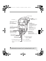
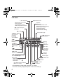
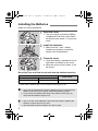
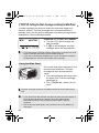
Friday, December 15, 2006 9:28 AM
English
A65_00.fm Page 1
A65_00.fm Page 2
Thursday, November 23, 2006 1:26 PM
Thank you for purchasing a Canon product.
The Canon Speedlite 580EX II is an EOS-dedicated, high-output flash
unit automatically compatible with E-TTL II, E-TTL, and TTL autoflash.
It can serve as an on-camera flash as well as a master unit or a slave
unit in a wireless, multiple-Speedlite system. It has the same dust- and
water-resistance as EOS-1D series cameras.
Read this instruction manual while also referring to your
camera’s instruction manual.
Before using the Speedlite, read this instruction manual and your camera’s
instruction manual to familiarize yourself with the Speedlite operations.
The basic operation is as easy as with normal AE shooting.
When the 580EX II is attached to an EOS camera, almost all automatic
exposure control for flash photography is handled by the camera.
It is almost the same as using the camera’s built-in flash if it has one. You can
think of the 580EX II as a built-in, high-output flash, but attached externally.
It becomes automatically compatible with the camera’s flash
metering mode (E-TTL ll, E-TTL, and TTL).
In accordance with the camera’s flash control system, the Speedlite controls
the flash automatically in the respective flash metering mode:
1. E-TTL II autoflash (evaluative flash metering with preflash reading/lens
distance information)
2. E-TTL autoflash (evaluative flash metering with preflash reading)
3. TTL autoflash (off-the-film metering for real-time flash metering)
Regarding the camera’s available flash metering modes, refer to the
“External Speedlite” specification in the “Specifications” of your
camera’s instruction manual.
The camera instruction manual’s chapter on flash photography will refer
to cameras having flash metering modes 1 or 2 as a Type-A camera
(compatible with E-TTL II or E-TTL). And cameras having flash
metering mode 3 (compatible with only TTL) are called Type-B
cameras.
* This instruction manual assumes that you are using the Speedlite
with a Type-A camera.
For Type-B cameras, see page 55.
2
A65_00.fm Page 3
Thursday, November 23, 2006 1:26 PM
Contents
1
Getting Started and Basic Operation ................................ 7
2 Using Flash ........................................................................ 13
3 Wireless Flash ................................................................... 33
4 Reference ........................................................................... 47
Conventions Used in this Manual
The <9> symbol in the text refers to the Select Dial.
The <8> symbol in the text refers to the Select/Set button.
The
symbol in the text refers to a Custom Function.
The operation procedures in this instruction manual assume that both
the camera and Speedlite’s power switches are ON.
Icons used in the text to indicate the respective buttons, dials, and
settings match the same icons found on the camera and Speedlite.
The (4) / (0) / (3) icons indicate that the respective function
remains in effect for 4 sec., 6 sec., or 16 sec. after you let go of the
button.
Reference page numbers are indicated by (p.**).
This instruction manual uses the following alert symbols:
: The Caution symbol indicates a warning to prevent shooting
problems.
: The Note symbol gives supplemental information.
3
A65_00.fm Page 4
Thursday, November 23, 2006 1:26 PM
Nomenclature
Catchlight panel (retracted) (p.19)
Built-in wide panel
(retracted) (p.20)
Flash head/
Wireless
transmitter
Contact cover
Wireless sensor
External power
source socket
AF-assist beam emitter
(p.49)
External metering
sensor (p.30)
Mounting foot (p.9)
PC terminal
Locking pin (p.9)
Case
Contacts
Bracket mounting
hole
Mini stand
Shoe
Mini stand pocket
4
A65_00.fm Page 5
Thursday, November 23, 2006 1:26 PM
Bounce angle
<z>
Bounce lock release
button (p.18)
LCD panel
< D>
Flash mode/
Slave setting button
(p.11, 22, 24/45, 46)
* <A>
LCD panel illumination/
Custom Function setting
button (p.6/27)
<J>
Pilot lamp/Test firing/
Wireless slave power
ON button (p.10/38)
<E>
High-speed sync
(FP flash)/Shutter curtain
synchronization button
(p.17/26)
Battery compartment
cover (p.8)
Battery compartment
lock lever (p.8)
<G>
Zoom button/
Wireless selector/
Wireless set button
(p.20/36, 39, 40, 41, 42, 45)
Flash exposure
confirmation lamp (p.11)
Mounting foot’s
lock lever (p.9)
Lock-release button (p.9)
Dust- and water-resistant
adapter
Power switch (p.10)
<L> : Power off
<K> : Power on
<9> Select Dial
* <8> Select/Set button
Asterisked buttons have functions which remain active for 8 sec. after you
press and let go of the button. The <B> illumination lasts for 12 sec.
5
A65_00.fm Page 6
Thursday, November 23, 2006 1:26 PM
LCD Panel
<9> ISO speed
Manual flash output level
Flash exposure
compensation amount
FEB compensation amount
<c> High-speed sync
(FP flash)
<d> Manual zoom
Aperture
FEB status
Stroboscopic flash count
Stroboscopic flash frequency
Manual flash 1/3-stop
increment indicator
Custom Function No.
Custom Function setting
<g> FEB
Zoom focal length
<8/a/b>
Auto external
metering/
E-TTL (ll)/
TTL autoflash
<s> Auto zoom
for image size
<8q>
Manual external
metering
Slave ID
<q/p>
Manual flash/Multi
(Stroboscopic)
flash
Slave ID
underscore
<u>
Custom Function
Flash range
scale/Flash
ratio scale
Flash ratio
<f> Flash
exposure compensation
Indicator
(meters)
< r>
Second-curtain sync
Firing mode
Master flash ON : W
Master flash OFF : Y
Slave flash :
X
Indicator (feet)
<y> Flash ratio
<x> Slave
<M> Master
<V> Flash bounce indicator
(Blinks for 7 down)
<w> Channel
To illuminate the LCD panel, press the <B> button.
The items actually displayed depend on the current settings.
6
A65_01.fm Page 7
Monday, January 22, 2007 2:22 PM
Getting Started and
Basic Operation
Installing the Batteries ............................................ 8
Attaching to the Camera......................................... 9
Turning on the Power Switch................................ 10
Fully Automatic Flash Shooting ............................. 11
Using E-TTL II and E-TTL Autoflash in the
Shooting Modes.................................................... 12
Cautions for firing continuous flashes
To avoid overheating and degrading the flash
head, do not fire more than 20 continuous
flashes. After 20 continuous flashes, allow a rest
time of at least 10 min.
If you fire more than 20 continuous flashes and
then fire more flashes in short intervals, the
inner overheating prevention function may be
activated to make the recycling time about 8 to
20 sec. If this occurs, allow a rest time of about
15 min. and the flash will then return to normal.
7
A65_01.fm Page 8
Thursday, November 23, 2006 1:26 PM
Installing the Batteries
Install four size-AA batteries.
1
Open the cover.
Use your thumb to press the battery
compartment lock lever, then slide it
as shown by the arrow c to open the
cover.
the batteries.
2 Install
Make sure the + and – battery
contacts are properly oriented as
shown in the compartment.
the cover.
3 Close
Close the battery compartment cover
and slide it as shown by the arrow.
X When the cover clicks in place, it will
be locked.
Recycling Time and Flash Count (with size-AA alkaline batteries)
Recycling Time
Quick Flash
Normal Flash
Approx. 0.1 - 2.5 sec.
Approx. 0.1 - 5 sec.
Flash Count
Approx. 100 - 700
Based on new size-AA alkaline batteries and Canon’s testing standards.
Quick flash enables a flash to be fired before flash-ready (p.10).
Using size-AA batteries other than the alkaline type may cause improper
battery contact due to the irregular shape of the battery contacts.
If you change the batteries after firing many flashes continuously, be
aware that the batteries might be hot.
Use a new set of four batteries of the same brand. When replacing the
batteries, replace all four at one time.
Size-AA Ni-MH or lithium batteries can also be used.
8
A65_01.fm Page 9
Thursday, November 23, 2006 1:26 PM
Attaching to the Camera
1
Attach the Speedlite.
Slip the Speedlite’s mounting foot into
the camera’s hot shoe all the way.
the Speedlite.
2 Secure
On the mounting foot, slide the lock
lever to the right.
X When the lock lever clicks in place, it
will be locked.
the Speedlite.
3 Detach
While pressing the lock-release
button, slide the lock lever to the left
and detach the Speedlite.
9
A65_01.fm Page 10
Thursday, November 23, 2006 1:26 PM
Turning on the Power Switch
1
Set the power switch to <K>.
X The flash recycling starts.
that the flash is ready.
2 Check
The pilot lamp will first turn green (ready
for quick flash), then red (flash ready).
Pressing the pilot lamp will fire a test
flash.
About Quick Flash
Quick flash enables a flash to be fired before flash-ready, when the pilot
lamp is still green.
Although the Guide No. will be 1/6 to 1/2 that of the full output, quick flash
is effective for near subjects and when you want a shorter recycle time.
Set the drive mode to single shooting. Quick flash cannot be used in the
continuous shooting, FEB, manual flash, and stroboscopic flash modes.
Quick flash can also be used during continuous flash shooting.
(C.Fn-06 → p.27)
About Auto Power Off
To save battery power, the power will turn off automatically after a
certain period (approx. 1.5 min. to 15 min.) of idle use. To turn on the
Speedlite again, press the camera’s shutter button halfway. Or press
the Speedlite’s test firing button.
Auto Power Off can also be disabled. (C.Fn-01 → p.27)
A test flash cannot be fired while the camera’s operation timer 4 or 0
is active.
The Speedlite’s settings will be retained in memory even after the power
is turned off. To retain the Speedlite’s settings after you replace the
batteries, turn off the power and replace the batteries within 1 minute.
10
A65_01.fm Page 11
Thursday, November 23, 2006 1:26 PM
Fully Automatic Flash Shooting
When you set the camera’s shooting mode to <V> (Program AE) or
<U> (Full Auto), E-TTL II/E-TTL fully automatic flash will make it as
easy as normal AE shooting in the <V> and <U> modes.
1
Set the Speedlite to <a>.
Press the <D> button so that
<a> is displayed.
the subject.
2 Focus
Press the shutter button halfway to focus.
X The shutter speed and aperture will
be displayed in the viewfinder.
Check that the <Q> icon is lit in the
viewfinder.
the picture.
3 TakeCheck
that the subject is within the
effective range displayed on the LCD
panel.
X Right before the shot is taken, a preflash
is fired, then the main flash is fired.
X If a standard flash exposure was
obtained, the flash exposure confirmation
lamp will light for about 3 sec.
<a> will be displayed on the LCD panel even if the camera is
compatible with E-TTL II.
If the flash exposure confirmation lamp does not light, move closer to the
subject and take the picture again. With a digital camera, you can also
increase the camera’s ISO speed.
11
A65_01.fm Page 12
Thursday, November 23, 2006 1:26 PM
Using E-TTL II and E-TTL Autoflash in the Shooting Modes
Just set the camera’s shooting mode to <W> (aperture-priority AE),
<X> (shutter-priority AE), or <q> (manual) and you can use E-TTL II/
E-TTL autoflash.
X
Select this mode when you want to set the shutter speed manually.
The camera will then automatically set the aperture matching the shutter
speed to obtain a standard exposure.
If the aperture display blinks, it means that the background exposure will
be underexposed or overexposed. Adjust the shutter speed until the
aperture display stops blinking.
Select this mode when you want to set the aperture manually.
The camera will then automatically set the shutter speed matching the
aperture to obtain a standard exposure.
If the background is dark like a night scene, a slow sync speed will be used
to obtain a standard exposure of both the main subject and background.
Standard exposure of the main subject is obtained with the flash, while a
W standard exposure of the background is obtained with a slow shutter speed.
Since a slow shutter speed will be used for low-light scenes, using a
tripod is recommended.
If the shutter speed display blinks, it means that the background
exposure will be underexposed or overexposed. Adjust the aperture until
the shutter speed display stops blinking.
Select this mode if you want to set both the shutter speed and aperture
manually.
q Standard exposure of the main subject is obtained with the flash. The
exposure of the background is obtained with the shutter speed and aperture
combination you set.
If you use the <Z> or <Y> shooting mode, the result will be the same as
using the <V> (Program AE) mode.
Flash Sync Speeds and Apertures Used
Shutter Speed Setting
Aperture Setting
V
Set automatically (1/60 sec. - 1/X sec.)
Automatic
X
Set manually (30 sec. - 1/X sec.)
Automatic
W
Set automatically (30 sec. - 1/X sec.)
Manual
q
Set manually (buLb, 30 sec. - 1/X sec.)
Manual
1/X sec. is the camera’s maximum flash sync speed.
12
A65_02.fm Page 13
Thursday, November 23, 2006 1:27 PM
Using Flash
f Flash Exposure Compensation ......................
g FEB ................................................................
7: FE Lock ........................................................
c High-speed Sync.............................................
Bounce Flash........................................................
H: Setting the Flash Coverage and Using
the Wide Panel .....................................................
q: Manual Flash .................................................
p: Stroboscopic Flash ..................................
r Second-Curtain Sync ....................................
C: Setting Custom Functions..........................
External Flash Metering........................................
Speedlite Control with the Camera’s Menu
Screen ..................................................................
14
15
16
17
18
20
22
24
26
27
30
32
13
A65_02.fm Page 14
Thursday, November 23, 2006 1:27 PM
f Flash Exposure Compensation
In the same way as normal exposure compensation, you can set
exposure compensation for flash. The flash exposure compensation
amount can be set up to ±3 stops in 1/3-stop increments. (If the
camera’s exposure compensation is in 1/2-stop increments, flash
exposure compensation will be in 1/2-stop increments.)
1
Select <f>.
Press the <8> button so that <f>
is displayed.
X The <f> icon and the flash
exposure compensation amount will
blink.
the flash exposure
2 Set
compensation amount.
Turn the <9> dial to set the amount.
To cancel the flash exposure
compensation, set the amount to
“+0.”
the <8> button.
3 Press
X Flash exposure compensation will be
set.
If flash exposure compensation has been set with both the Speedlite and
camera, the Speedlite’s flash exposure compensation amount will override
the camera’s.
Setting the flash exposure compensation can be limited to only the <9>
dial. (C.Fn-13 → p.27)
14
A65_02.fm Page 15
Thursday, November 23, 2006 1:27 PM
g FEB
You can take three flash shots while automatically changing the flash
output for each shot up to ±3 stops in 1/3-stop increments (1/2-stop
increments if the camera enables only 1/2-stop increments). This is
called FEB (Flash Exposure Bracketing).
1
Select <g>.
Press the <8> button so that <g>
is displayed.
X The <g> icon and bracketing
amount will blink.
the flash exposure bracketing
2 Set
amount.
Turn the <9> dial to set the amount.
the <8> button.
3 Press
X FEB will be set.
After the three shots are taken, FEB will be cancelled automatically.
For FEB, set the camera’s drive mode to single shooting. Be sure the
flash is ready before shooting.
You can also combine FEB with flash exposure compensation and FE
lock.
You can prevent the FEB from being cancelled automatically after the
three shots are taken. (C.Fn-03 → p.27)
The FEB shooting sequence can be changed. (C.Fn-04 → p.27)
15
A65_02.fm Page 16
Thursday, November 23, 2006 1:27 PM
7: FE Lock
FE (flash exposure) lock locks the correct flash exposure setting for any
part of the scene.
With <a> displayed on the LCD panel, you press the camera’s
<7> button. If the camera does not have the <7> button, press the
<P> button.
1 Focus the subject.
the <7> button. (3)
2 Press
Aim the subject at the center of the
viewfinder and press the <7>
button.
X The Speedlite will fire a preflash and
the required flash output for the
subject is retained in memory.
X “FEL” will be displayed in the
viewfinder for 0.5 sec.
Each time you press the <7>
button, a preflash will be fired and a
new flash exposure setting will be
locked.
If the subject is too far away and underexposure will result, the <Q> icon
will blink in the viewfinder. Move closer to the subject and try the FE lock
again.
If <a> is not displayed on the LCD panel, FE lock cannot be set.
If the subject is too small, FE lock might not be very effective.
16
A65_02.fm Page 17
Thursday, November 23, 2006 1:27 PM
c High-speed Sync
With high-speed sync (FP flash), the flash can synchronize with all
shutter speeds. This is convenient when you want to use aperture
priority for fill-flash portraits.
Select <c>.
Press the <E> button so that
<c> is displayed.
In the viewfinder, check that the <F>
icon is displayed.
If you set a shutter speed that is the same or slower than the camera’s
maximum flash sync speed, <F> will not be displayed in the viewfinder.
With high-speed sync, the faster the shutter speed, the shorter the
effective flash range will become. Check the LCD panel for the effective
flash range.
To return to normal flash, press the <E> button again. The <c>
icon will disappear.
Stroboscopic flash cannot be set.
17
A65_02.fm Page 18
Thursday, November 23, 2006 1:27 PM
Bounce Flash
By pointing the flash head toward a wall or ceiling, the flash will bounce
off the surface before illuminating the subject. This can soften shadows
behind the subject for a more natural-looking shot. This is called bounce
flash.
Set the Bounce Direction
Hold down the <z> button and turn the flash head.
If the flash coverage is set automatically, the flash coverage will be fixed
to 50mm.
The LCD panel will also display <O> mm.
You can also set the flash coverage manually.
If the wall or ceiling is too far away, the bounced flash might be too weak
and result in underexposure.
The wall or ceiling should be a plain, white color for high reflectance. If
the bounce surface is not white, a color cast may result in the picture.
After you take the shot, if the flash exposure confirmation lamp does not
light, use a larger aperture opening and try again.
18
A65_02.fm Page 19
Thursday, November 23, 2006 1:27 PM
Creating a Catchlight
With the catchlight panel, you can create a catchlight in the subject’s
eyes to add life to the facial expression.
the flash head upward by
1 Point
90°.
out the wide panel.
2 Pull
X The catchlight panel will come out at
the same time.
the wide panel back in.
3 Push
Push in only the wide panel.
Follow the same procedure as for
bounce flash.
Point the flash head straight ahead and then upward by 90°. The
catchlight will not work if you swing the flash head left or right.
For maximum catchlight effect, stay within 1.5 m/4.9 ft of the subject.
Closeup Flash Shooting
When shooting a subject within about 0.5 - 2 m (1.6 - 6.6 ft) away, hold
down the <z> button and tilt the flash head downward by 7° to
illuminate the lower part of the image.
19
A65_02.fm Page 20
Wednesday, December 6, 2006 1:25 PM
H: Setting the Flash Coverage and Using the Wide Panel
The flash coverage can be set to match the lens focal length from
24mm to 105mm. The flash coverage can be set automatically or
manually. Also, with the built-in wide panel, the flash coverage can be
expanded for 14mm wide-angle lenses.
Press the <G> button.
Turn the <9> dial to change the
flash coverage.
If <d> is not displayed, the flash
coverage will be set automatically.
If you set the flash coverage manually, make sure it covers the lens focal
length so that the picture will not have a dark periphery.
If you use a commercially-available sync cord to connect the camera to
the Speedlite’s PC terminal, set the flash zoom manually.
Using the Wide Panel
Pull out the wide panel and place it over
the flash head as shown. The flash
coverage will then be extended for
14mm.
The catchlight panel will come out at
the same time. Push the catchlight
panel back in.
The <G> button will not
work.
The flash coverage will not be compatible with the EF15mm f/2.8 Fisheye
lens.
If you use bounce flash with the wide panel in place, the entire display on
the LCD panel will blink as a warning. Since the subject will be
illuminated by both the bounce flash and direct flash, it will look
unnatural.
Pull out the wide panel gently. Using excessive force may detach the
wide panel.
20
A65_02.fm Page 21
Thursday, November 23, 2006 1:27 PM
Auto Zoom for Image Size
EOS DIGITAL cameras have one of three image sizes. The lens’
effective focal length will differ depending on the camera’s image size.
The Speedlite automatically recognizes the EOS DIGITAL camera’s
image size and automatically sets the flash coverage for lens focal
lengths from 24mm to 105mm.
When the Speedlite is attached to a compatible camera, <s> will
appear on the Speedlite’s LCD panel.
Auto zoom can be disabled. (C.Fn-09 → p.27)
21
A65_02.fm Page 22
Thursday, November 23, 2006 1:27 PM
q: Manual Flash
You can set the flash output from 1/128 power to 1/1 full power in 1/3stop increments.
Use a hand-held flash meter to determine the required flash output to
obtain a correct flash exposure.
1
Press the <D> button so
that <q> is displayed.
the flash output.
2 SetPress
the <8> button.
X The flash output blinks.
Turn the <9> dial to set the flash
output, then press the <8> button.
Press the shutter button halfway to
see the effective flash range
displayed.
Flash Output Display
When you change the flash output during shooting, the table below
makes it easier to see how the stop changes such as 1/2 -0.3 → 1/2 →
1/2 +0.3. You can see how the stop changes when you increase or
decrease the flash output.
For example, when you decrease the flash output to 1/2, 1/2 -0.3, or 1/2
-0.7, and then increase the flash output to more than 1/2, 1/2 +0.3, 1/2
+0.7, and 1/1 will be displayed.
Figures for decreased flash output →
1/1 -0.3
1/1 -0.7
1/2 -0.3
1/2 -0.7
1/2
1/2 +0.7
1/2 +0.3
1/4 +0.7
1/4 +0.3
← Figures for increased flash output
(Example)
1/1
22
1/4
•••
•••
A65_02.fm Page 23
Thursday, November 23, 2006 1:27 PM
Metered Manual Flash Exposures
When the Speedlite is attached to an EOS-1D series camera, you can
set the flash level manually for closeup subjects.
1 Set the camera and Speedlite.
Set the camera’s shooting mode to <q> or <W>.
Set the Speedlite to manual flash.
2 Focus the subject.
Focus manually.
3 Set up an 18% gray card.
Place the gray card at the subject’s position.
In the viewfinder, the entire spot metering circle at the center
should cover the gray card.
4 Press the <7> button. (3)
X The Speedlite will fire a preflash and the required flash output for
the subject is retained in memory.
X On the right side of the viewfinder, the exposure level indicator
will show the flash exposure level for the correct flash exposure.
5 Set the flash exposure level.
Adjust the Speedlite’s manual flash level and the
camera aperture so that the flash exposure level
aligns with the standard exposure index.
6 Take the picture.
Remove the gray card and take the picture.
This feature works only with EX-series Speedlites with manual flash coupled
with an EOS-1D series camera.
23
A65_02.fm Page 24
Thursday, November 23, 2006 1:27 PM
p: Stroboscopic Flash
With stroboscopic flash, a rapid series of flashes is fired. It can be used
to capture multiple images of a moving subject in a single photograph.
You can set the firing frequency (number of flashes per sec. expressed
as Hz), the number of flashes, and the flash output.
1
Press the <D> button so
that <p> is displayed.
the item to be set.
2 Select
Press the <8> button to select the
item (blinks).
the desired number.
3 SetTurn
the <9> dial to set the number,
then press the <8> button.
X The next item to be set will blink.
After you set the flash output and
press the <8> button, all the
settings will be displayed.
Calculating the Shutter Speed
During stroboscopic flash, the shutter remains open until the firing
stops. Use the formula below to calculate the shutter speed and set it
with the camera.
Number of flashes ÷ Firing frequency = Shutter speed
For example, if the number of flashes is 10 and the firing frequency is
5 Hz, the shutter speed should be at least 2 sec.
24
A65_02.fm Page 25
Thursday, November 23, 2006 1:27 PM
To avoid overheating and deteriorating the flash head, do not use stroboscopic
flash more than 10 times in succession. After 10 times, allow the Speedlite to
rest for at least 15 min. If you try to use the stroboscopic flash more than 10
times in succession, the firing might stop automatically to protect the flash
head. If this happens, allow the Speedlite to rest for at least 15 min.
Stroboscopic flash is most effective with a highly reflective subject
against a dark background.
Using a tripod, a remote switch, and external power source is recommended.
A flash output of 1/1 or 1/2 cannot be set for stroboscopic flash.
Stroboscopic flash can be used with “buLb.”
If the number of flashes is displayed as - -, the firing will continue until the shutter closes or
the battery is exhausted. The number of flashes will be limited as shown by the table below.
Maximum Stroboscopic Flashes
Hz
Flash Output
1/4
1/8
1/16
1/32
1/64
1/128
Hz
Flash Output
1/4
1/8
1/16
1/32
1/64
1/128
1
2
3
4
5
6-7
8-9
7
14
30
60
90
100
6
14
30
60
90
100
5
12
30
60
90
100
4
10
20
50
80
100
4
8
20
50
80
100
3
6
20
40
70
90
3
5
10
30
60
80
10
11
2
4
8
20
50
70
2
4
8
20
40
70
12 - 14 15 - 19 20 - 50 60 - 199
2
4
8
20
40
60
2
4
8
18
35
50
2
4
8
16
30
40
2
4
8
12
20
40
If the number of flashes is displayed as - -, the maximum number of flashes will
be as shown by the table below regardless of the firing frequency.
Flash Output
Flash Count
1/4
2
1/8
4
1/16
8
1/32
12
1/64
20
1/128
40
25
A65_02.fm Page 26
Thursday, November 23, 2006 1:27 PM
r Second-Curtain Sync
With a slow shutter speed, you can create a light trail following the
subject. The flash fires right before the shutter closes.
Press the <E> button so that
<r> is displayed.
Second-curtain sync works well in the camera’s “buLb” mode.
To return to normal flash, press the <E> button again. The <r>
icon will disappear.
With E-TTL II/E-TTL, two flashes will be fired even at slow shutter
speeds. The first flash is only the preflash, and not a malfunction.
Stroboscopic flash cannot be set.
Wireless flash cannot be set.
26
A65_02.fm Page 27
Thursday, November 23, 2006 1:27 PM
C: Setting Custom Functions
You can customize Speedlite features to suit your shooting preferences.
You do this with Custom Functions.
Custom
Function
No.
Function
C.Fn-00 Distance indicator display
C.Fn-01 Auto power off
Setting
No.
0
1
0
1
0
C.Fn-02 Modeling flash
C.Fn-03 FEB auto cancel
C.Fn-04 FEB sequence
C.Fn-05 Flash metering mode
C.Fn-06
Quickflash with continuous
shot
C.Fn-07 Test firing with autoflash
C.Fn-08 AF-assist beam firing
C.Fn-09 Auto zoom for sensor size
C.Fn-10 Slave auto power off timer
C.Fn-11
Slave auto power off cancel
C.Fn-12
Flash recycle with external
power source
Flash exposure metering
C.Fn-13
setting
1
2
3
0
1
0
1
0
1
2
3
0
1
0
1
0
1
0
1
0
1
0
1
0
1
0
1
Settings & Description
Meters (m)
Feet (ft)
Enabled
Disabled
Enabled (Depth-of-field preview
button)
Enabled (Test firing button)
Enabled (with both buttons)
Disabled
Enabled
Disabled
0→−→+
−→0→+
E-TTL II/E-TTL
TTL
External metering : Auto
External metering : Manual
Disabled
Enabled
1/32
Full output
Enabled
Disabled
Enabled
Disabled
60 minutes
10 minutes
Within 8 hours
Within 1 hour
Flash and external power
External power source
Speedlite button and dial
Speedlite dial only
Reference
page
p.10
p.44
p.15
p.12
p.55
p.30
p.30
p.10
p.49
p.21
p.39
p.48
p.14
27
A65_02.fm Page 28
Monday, December 18, 2006 2:52 PM
1
Hold down the <A> button
until <u> is displayed.
the Custom Function No.
2 Select
Turn the <9> dial to set the Custom
Function No.
3
Change the setting.
Press the <8> button.
X The Custom Function No. blinks.
X Turn the <9> dial to set the desired
number, then press the <8> button.
X After you set the Custom Function
and press the <D> button, the
camera will be ready to shoot.
28
A65_02.fm Page 29
Thursday, November 23, 2006 1:27 PM
C.Fn-02-3: Convenient when you want to check the depth of field. (p.44)
C.Fn-12: If an external power source is used, the flash recycling is
powered concurrently by the internal batteries and external
power source. In this case, when the internal batteries
become exhausted first, shooting might not be possible. If 1
is set, the flash recycling will be powered only by the
external power source. The internal batteries will thereby
last longer. Note that even if you set it to 1, the Speedlite will
still require internal batteries for flash control.
C.Fn-05-1 is geared for EOS-series film cameras.
Do not set it if you have a, EOS DIGITAL camera or the EOS REBEL T2/
300X. If C.Fn-05-1 is set for such cameras, the flash control will not work
properly. The flash might not fire or it might fire only at full output.
With Type-A cameras, if C.Fn-05-1 is set, wireless autoflash shooting will
not be possible.
If “AF-assist beam OFF” is set with the Speedlite or camera, the AFassist beam will not be emitted.
With Type-B cameras, even if C.Fn-05-0 is set, E-TTL II/E-TTL autoflash will
not work.
29
A65_02.fm Page 30
Thursday, November 23, 2006 1:27 PM
External Flash Metering
The flash reflected off the subject is metered by an external metering
sensor in real time. When the standard flash exposure is attained, the
flash output is cutoff automatically. Auto external metering compatible
with the EOS-1D Mark III and manual external metering compatible with
all EOS cameras are provided.
8: Auto External Metering
Set auto external metering.
Set the Speedlite Custom Function to
C.Fn-05-2. (p.27)
With auto external metering, the camera’s ISO speed and aperture will
be set automatically in real-time by the Speedlite.
Auto external metering will also work with flash exposure compensation
(p.14) and FEB (p.15).
8q: Manual External Metering
1
Set manual external metering.
Set the Speedlite Custom Function to
C.Fn-05-3. (p.27)
the Speedlite to the camera’s
2 Set
ISO speed.
Press the <8> button so the ISO
speed blinks.
Turn the <9> dial to set the ISO
speed, then press the <8> button.
30
A65_02.fm Page 31
Thursday, November 23, 2006 1:27 PM
the Speedlite to the camera’s
3 Set
aperture setting.
Press the <8> button so the
aperture setting blinks.
Turn the <9> dial to set the
aperture, then press the <8> button.
After completing the settings, press the
shutter button halfway. The effective flash
range will be displayed on the Speedlite’s
LCD panel.
With manual external metering, you can connect the camera to the
Speedlite’s PC terminal with a sync cord and place the Speedlite at a
different position from the camera.
You cannot connect a Speedlite to another Speedlite’s PC terminal with
a sync cord. The second Speedlite will not fire.
31
A65_02.fm Page 32
Monday, December 18, 2006 2:52 PM
Speedlite Control with the Camera’s Menu Screen
If the Speedlite is attached to an EOS camera which has a Speedlite
control function, it can control the Speedlite as shown below. For the
menu operation procedure, refer to your camera’s instruction manual.
Setting Speedlite functions
The settable functions will vary depending on the flash mode.
· Flash mode
· Shutter sync (1st/2nd curtain)
· FEB
· Flash exposure compensation
· Flash metering mode
· Flash firing
· Clear Speedlite settings
Speedlite Custom Functions
· C.Fn-00 - 13, Total 14
Clear All Speedlite Custom Functions
Only C.Fn-00 will not be cleared.
Flash function settings screen*
Flash C.Fn settings screen*
* Screens from the EOS-1D Mark III.
If flash exposure compensation has already been set with the Speedlite,
flash exposure compensation cannot be set with the camera. To set it with
the camera, first set the Speedlite’s flash exposure compensation to zero.
If any Speedlite Custom Functions and flash function settings other than
flash exposure compensation have been set by both the camera and
Speedlite, the latest setting will take effect.
32
A65_03.fm Page 33
Thursday, November 23, 2006 1:27 PM
Wireless Flash
About Wireless Flash............................................
Wireless Settings..................................................
Fully Automatic Wireless Flash ............................
Flash Ratio with E-TTL II ......................................
Setting the Flash Output for Each Slave ..............
Setting Manual Flash and Stroboscopic Flash
with the Slave .......................................................
34
36
37
41
45
46
33
A65_03.fm Page 34
Thursday, November 23, 2006 1:27 PM
About Wireless Flash
With multiple Canon Speedlites having the wireless flash feature, you
can create various lighting effects with the same ease as using normal
E-TTL II autoflash.
The settings you input with the 580EX II (master unit) attached to the
camera are also automatically transmitted to the slave units which are
controlled by the master unit via wireless. Therefore, you need not
operate the slave unit(s) at all during the shoot.
The basic wireless set-up is illustrated below. All you need to do is set
the master unit to <a> enable wireless E-TTL II autoflash (p.37).
Note that with Type-A cameras prior to the EOS-1D Mark ll and EOS
ELAN 7NE/ELAN 7N/30V/33V, E-TTL autoflash will be used instead.
Positioning and Operation Range
Indoors
x
15m
(49.2ft.)
Outdoors
M
10m
(32.8ft.)
80
o
8m (26.2ft.) 12m (39.4ft.)
Any flash exposure compensation, high-speed sync (FP flash), FE lock,
FEB, manual flash, and stroboscopic flash settings set with the master
unit will all be automatically transmitted to the slave units.
Even with multiple slave units, all of them will be controlled in the same
way via wireless.
A 580EX II set as a slave unit can also be controlled by wireless by
Speedlite Transmitter ST-E2 (optional).
Hereinafter, the “master unit” will refer to a 580EX II attached to the
camera, and a “slave unit” will be a wireless 580EX II.
34
A65_03.fm Page 35
Thursday, November 23, 2006 1:27 PM
Multi-Speedlite, Wireless Lighting Configurations
You can create two or three slave groups and set the flash ratio for ETTL II autoflash shooting (p.41 - 45).
Wireless flash with two slave groups (p.41)
Indoors
15m
(49.2ft.)
A
Outdoors
10m
(32.8ft.)
80
B
o
8m (26.2ft.) 12m (39.4ft.)
Wireless flash with three slave groups (p.43)
Indoors
C
15m
(49.2ft.)
A
Outdoors
10m
(32.8ft.)
80
B
o
8m (26.2ft.) 12m (39.4ft.)
35
A65_03.fm Page 36
Thursday, November 23, 2006 1:27 PM
Wireless Settings
You can switch between normal flash and wireless flash. For normal
shooting, be sure to set the wireless setting to OFF.
Master Unit Setting
1
Press the <H> button for 2
sec. or longer until the display
blinks as shown on the left.
it as the master unit.
2 SetTurn
the <9> dial until <M>
blinks, then press the <8> button.
X <M> and <w> will be
displayed, and the Speedlite is set as
the master unit.
Slave Unit Setting
Set it as a slave unit.
Do the “Master Unit Setting”
procedure above. For step 2, turn the
<9> dial until <x> blinks,
then press the <8> button.
X <x> and <w> will be
displayed, and the Speedlite is set as
a slave unit.
36
A65_03.fm Page 37
Thursday, November 23, 2006 1:27 PM
Fully Automatic Wireless Flash
This method has all the Speedlites fire at the same flash output with ETTL II autoflash controlling the total flash output.
1
Set the camera-attached 580EX II
as the master unit.
the other 580EX II
2 Set
Speedlites(s) as the wireless
slave unit(s).
the communication
3 Check
channel.
If the master unit and slave unit(s) are
set to a different channel, set them all
to the same channel (p.40).
the camera and
4 Position
Speedlites.
Position the Speedlites within the
range shown on the next page.
the master unit’s flash mode
5 Set
to <a>.
For shooting, <a> will also be
set automatically for the slave unit(s).
that the flash is ready.
6 Check
When the slave unit(s) is ready to fire,
the AF-assist beam will blink at 1-sec.
intervals.
37
A65_03.fm Page 38
Thursday, November 23, 2006 1:27 PM
the flash operation.
7 Check
Press the master unit’s test firing
button.
X The slave unit will fire. If the flash
does not fire, adjust the slave unit’s
angle toward the master unit and
distance from the master unit.
and shoot.
8 SetSetthethecamera
camera in the same way as
with normal flash shooting.
Indoors
15m (49.2ft.)
Outdoors
10m (32.8ft.)
80
o
8m (26.2ft.)
12m (39.4ft.)
Use the mini stand (tripod socket provided) to prop up the slave unit.
Use the bounce feature to swing the slave unit so that its wireless
sensor faces the master unit.
Indoors, the wireless signal can also bounce off the wall so there is
more leeway in positioning the slave unit(s).
After positioning the slave unit(s), be sure to test the wireless flash
operation before shooting.
Do not place any obstacles between the master unit and slave
unit(s). Obstacles can block the transmission of wireless signals.
38
A65_03.fm Page 39
Thursday, November 23, 2006 1:27 PM
The Speedlite’s zoom setting will be set automatically to 24mm. It is possible to
change the master unit’s zoom setting. However, note that the master unit
transmits wireless signals to the slave unit(s) with the preflash. Therefore, the
flash coverage must cover the slave unit’s position. If you change the master
unit’s zoom setting, be sure to test the wireless flash operation before shooting.
If the slave unit’s auto power off takes effect, press the master unit’s test
firing button to turn on the slave unit.
A test flash cannot be fired while the camera’s operation timer 4 or 0 is active.
The slave unit’s auto power off time can be changed. (C.Fn-10 → p.27)
The time during which the slave unit’s auto power off can be canceled by
the master unit can be changed. (C.Fn-11 → p.27)
Master Unit’s Flash ON/OFF
You can disable the master unit from firing so that only the slave unit(s)
will fire a flash.
1
Press the <G> button
so that the display blinks as
shown on the left.
the master unit’s flash
2 Disable
firing.
Turn the <9> dial to select <Q>,
then press the <8> button.
X The icon will change to <Y>.
Even if you disable the master unit’s flash firing, it will still fire a preflash to
transmit wireless signals.
39
A65_03.fm Page 40
Thursday, November 23, 2006 1:27 PM
Using Fully Automatic Wireless Flash
Flash exposure compensation and other settings set with the master
unit will also be automatically set in the slave units. Thus, you need not
operate the slave unit(s). Wireless flash with the following settings can
be done in the same way as with normal flash shooting.
· Flash exposure compensation
· High-speed sync (FP flash)
· FE lock
· FEB
· Manual flash
· Stroboscopic flash
With FE lock, if even one Speedlite will result in underexposure, the <Q>
icon will blink in the viewfinder. Open the aperture more or move the slave
unit closer to the subject.
Setting the Communication Channel
If there is another Canon wireless flash system nearby, you can change
the channel No. to prevent signal confusion. Both the master and slave
units must be set to the same channel No.
1
Press the <G> button
so that <w> blinks.
the channel No.
2 SetTurn
the <9> dial to select the
channel number, then press the
<8> button.
40
A65_03.fm Page 41
Thursday, November 23, 2006 1:27 PM
Flash Ratio with E-TTL II
With one master unit and one slave unit or two slave groups, you can
set the flash ratio for E-TTL II autoflash shooting.
The example below has two slave units and the master unit disabled
from firing.
15m (49.2ft.)
10m (32.8ft.)
Indoors
A
B
Outdoors
80
o
12m (39.4ft.)
8m (26.2ft.)
Setting the Slave Units
Two slave units can be assigned to different slave groups by setting the
slave ID.
the wireless mode to
1 Set
<x>. (p.36)
the <G> button
2 Press
so that <1> blinks.
41
A65_03.fm Page 42
Thursday, November 23, 2006 1:27 PM
the slave ID.
3 SetPress
the <8> button.
X Slave ID <1> will be set.
For the other slave unit, do steps 1
and 2, turn the <9> dial to select
<2>, then press the <8> button.
Slave ID <2> will be set.
Setting the Master Unit and Shooting
the wireless mode to
1 Set
<M>. (p.36)
the master unit’s flash
2 Disable
firing. (p.39)
the <G> button
3 Press
so that <y> blinks.
the flash ratio.
4 Select
Turn the <9> dial to select <l>,
then press the <8> button.
the flash ratio.
5 SetTurn
the <9> dial to set the flash
ratio.
and shoot.
6 SetSetthethecamera
camera in the same way as
with normal flash shooting.
With the EOS ELAN ll/ELAN ll E/50/50E, EOS REBEL G/500N, EOS IX,
EOS IX Lite/IX7, EOS REBEL 2000/300, and REBEL XS N/ REBEL G ll/
EOS 3000N/66, the flash ratio cannot be set with multiple Speedlites.
42
A65_03.fm Page 43
Thursday, November 23, 2006 1:27 PM
The flash ratio range of 8:1 - 1:1 - 1:8 is equivalent to 3:1 - 1:1 - 1:3 in
stops (1/2-stop increments).
The flash ratio under the Z mark is shown in parentheses below the scale.
(5.6:1) (2.8:1) (1.4:1) (1:1.4) (1:2.8) (1:5.6)
Wireless Flash with Three Slave Groups
15m (49.2ft.)
C
10m (32.8ft.)
Indoors
A
B
Outdoors
80
o
12m (39.4ft.)
8m (26.2ft.)
You can have slave groups A and B and also add slave group C. You can use
slave groups A and B to obtain the standard flash exposure of the subject,
and slave group C to illuminate the background to eliminate shadows.
1
Set the slave units.
See “Setting the Slave Units” on page
41 to set the slave unit’s ID to <1>,
<2>, or <3>.
For slave <3>, also set the flash
exposure compensation as necessary.
43
A65_03.fm Page 44
Thursday, November 23, 2006 1:27 PM
the master unit and shoot.
2 SetFollow
“Setting the Master Unit and
Shooting” on page 42. In step 4,
select <k>.
If <yl> is set, the slave unit in slave group <3> will not fire.
If you point the slave unit in slave group <3> toward the subject, the
subject will be overexposed.
Modeling Flash
If the camera has a depth-of-field preview button, pressing it will fire the
flash continuously for 1 sec. This is called the modeling flash.
It enables you to see the shadow effects on the subject and the lighting
balance. You can fire the modeling flash for both wireless and normal
flash shooting.
Do not fire the modeling flash more than 10 consecutive times. If you
fire the modeling flash 10 consecutive times, allow the Speedlite to
rest for at least 10 min. to avoid overheating and deteriorating the flash
head.
The modeling flash cannot be fired with the EOS REBEL 2000/300 and
Type-B cameras (p.2).
About Slave Group Control
Slave group A
ID = A
44
ID = A
ID = A
For example, if you have the slave ID set
to <1> for three slave units, all three
slave units will be controlled as if they
were one Speedlite in slave group A.
A65_03.fm Page 45
Thursday, November 23, 2006 1:27 PM
Setting the Flash Output for Each Slave
With manual flash and multiple Speedlites, you can set a different flash
output for each slave unit.
All settings are done with the master unit.
1
Press the <D> button so
that <q> is displayed.
the <G> button
2 Press
so that <y> blinks.
the flash ratio.
3 Select
Turn the <9 > dial to select <l>
or <j>, then press the <8>
button.
the flash output.
4 SetPress
the <8> button.
X The slave ID <m> will blink.
Turn the <9> dial to set the flash
output for <m>, then press the <8>
button.
The slave ID <n> will blink. Turn the
<9> dial to set the flash output for
<n>, then press the <8> button.
The slave ID <o> will blink. Turn the
<9> dial to set the flash output for
<o>, then press the <8> button.
X All the slave IDs will light.
45
A65_03.fm Page 46
Thursday, November 23, 2006 1:27 PM
Setting Manual Flash and Stroboscopic Flash with the Slave
Manual flash or stroboscopic flash can be set manually with the slave
unit. As with studio flash units, you can set the flash output individually
with the slave units for wireless or manual flash.
Manual Flash
Hold down the <D> button for 2
sec. or more.
X <q> will blink.
Set the manual flash output (p.22).
Stroboscopic Flash
Hold down the <D> button for
2 sec. or more.
X <q> will blink.
Press the <D> button again
and <p> will blink.
Set the stroboscopic flash (p.24).
46
A65_04.fm Page 47
Thursday, November 23, 2006 1:28 PM
Reference
580EX II System...................................................
Troubleshooting Guide .........................................
Specifications .......................................................
Using a Type-B Camera .......................................
48
50
52
55
47
A65_04.fm Page 48
Thursday, November 23, 2006 1:28 PM
580EX II System
c Speedlite 580EX II (On-camera/Master unit)
d Speedlite Transmitter ST-E2
Dedicated transmitter for wireless control of 580EX II/430EX set as
slave units.
e Compact Battery Pack CP-E4
Compact, lightweight, and portable external power pack. Provides
the same level of dust- and water-resistance as the 580EX II. It uses
eight size-AA alkaline or Ni-MH batteries. It can also use size-AA
lithium batteries.
f EX-series Speedlite with slave function
g Off-Camera Shoe Cord OC-E3
Enables the 580EX II to be connected to the camera up to 60 cm/2 ft
away. Provides the same level of dust- and water-resistance as the
580EX II. All of the EOS camera’s automatic functions can be used.
h Speedlite Bracket SB-E2
For the external power pack, use e above. If a non-Canon, external
power pack is used, it may cause malfunction.
48
A65_04.fm Page 49
Monday, December 18, 2006 2:34 PM
About Color Temperature Information Transmission
When the flash fires, the color temperature information is transmitted to
the EOS DIGITAL camera. This feature optimizes the flash picture’s
white balance. When the camera’s white balance is set to <A> or
<Q>, it will work automatically.
To see if this feature works with your camera, see “White Balance”
under “Specifications” in your camera’s instruction manual.
About the AF-Assist Beam
Under low-light or low-contrast conditions, the built-in AF-assist beam
will be emitted automatically to make it easier to autofocus. The AFassist beam works with all EOS cameras. The AF-assist beam is
compatible with 28mm and longer lenses. The effective range is shown
below.
Position
Effective Range
Center
0.6 - 10 m / 2.0 - 32.8 ft.
Periphery
0.6 - 5 m / 2.0 - 16.4 ft.
49
A65_04.fm Page 50
Thursday, November 23, 2006 1:28 PM
Troubleshooting Guide
If there is a problem, refer to this Troubleshooting Guide.
The Speedlite does not fire.
The batteries are installed in the wrong orientation.
X Install the batteries in the correct orientation. (p.8)
The Speedlite’s internal batteries are exhausted.
X If the flash recycling time takes 30 sec. or longer, replace the
batteries. (p.8)
X Install the Speedlite’s internal batteries even when you use an
external power source. (p.8)
The Speedlite is not attached securely to the camera.
X Attach the Speedlite’s mounting foot securely to the camera. (p.9)
The electrical contacts of the Speedlite and camera are dirty.
X Clean the contacts. (p.9)
The slave unit does not fire.
The slave’s wireless mode is not set to <x>.
X Set it to <x>. (p.36)
The slave unit(s) is not positioned properly.
X Place the slave unit within the master unit’s transmission range.
(p.38)
X Point the slave unit(s)’s sensor toward the master unit. (p.38)
The power turns off by itself.
After 90 sec. of idle operation, auto power off took effect.
X Press the shutter button halfway or press the test firing button.
(p.10)
The entire LCD panel blinks.
The wide panel has been pulled out for bounce flash.
X Retract the wide panel. (p.20)
50
A65_04.fm Page 51
Thursday, November 23, 2006 1:28 PM
Auto zoom does not work.
The Speedlite is not attached securely to the camera.
X Attach the Speedlite’s mounting foot securely to the camera. (p.9)
The flash range scale bars blink.
The flash head has been tilted down by 7°.
X Change the bounce position. (p.19)
The periphery or bottom of the picture looks dark.
When you set the flash coverage manually, the setting was a higher
number than the lens focal length, resulting in a dark periphery.
X Set the flash coverage that is a lower number than the lens focal
length or set it to auto zoom. (p.20)
If only the bottom of the picture looks dark, you were too
close to the subject.
X If the subject is closer than 2 m/6.6 ft, tilt the flash head downward
by 7° (bounce flash). (p.19)
The flash exposure is underexposed or overexposed.
There was a highly reflective object (glass window, etc.) in the picture.
X Use FE lock. (p.16)
The subject looks very dark or very bright.
X Set flash exposure compensation. For a dark subject, set a
decreased flash exposure. And for a bright subject, set an
increased flash exposure. (p.14)
You used high-speed sync.
X With high-speed sync, the effective flash range will be shorter. Make
sure the subject is within the effective flash range displayed. (p.17)
The picture is really blurred.
The shooting mode was set to <W>, and the scene was dark.
X Use a tripod or set the shooting mode to <V>. (p.12)
51
A65_04.fm Page 52
Thursday, November 23, 2006 1:28 PM
Specifications
• Type
Type:
Compatible cameras:
Guide No.:
Flash coverage:
On-camera, E-TTL II/E-TTL/TTL autoflash Speedlite
Type-A EOS cameras (E-TTL II/E-TTL autoflash)
Type-B EOS cameras (TTL autoflash)
58/190 (at 105mm focal length, ISO 100 in meters/feet)
24 - 105mm (14mm with wide panel)
· Auto zoom (Flash coverage set automatically to match the
lens focal length and image size)
· Manual zoom
· Swinging/tilting flash head (bounce flash)
Normal flash: 1.2 ms or shorter, Quick flash: 2.3 ms or shorter
Flash duration:
Color temperature
information transmission: Flash color temperature information transmitted to camera
when flash is fired
• Exposure Control
Exposure control system: E-TTL II/E-TTL/TTL autoflash, auto/manual external
metering, manual flash
Effective flash range:
Normal flash: Approx. 0.5 - 30 m / 1.6 - 98.4 ft.
(With EF50mm f/1.4 lens Quick flash: 0.5 - 7.5 m / 1.6 - 24.6 ft. (min), 0.5 - 21 m / 1.6 at ISO 100)
68.9 ft. (max)
High-speed sync: 0.5 - 15 m / 1.6 - 49.2 ft. (1/250 sec.)
Flash exposure
compensation:
Manual, FEB: ±3 stops in 1/3-stop increments (Manual and
FEB can be combined)
FE lock:
With <7> button or <P> button
High-speed sync:
Provided
Stroboscopic flash:
Provided (1 - 199 Hz)
Flash exposure
confirmation:
Pilot lamp lights
• Flash Recycling (with size-AA alkaline batteries)
Recycling time/
Flash-ready indicator:
52
Normal flash: Approx. 0.1 - 5 sec. / Red pilot lamp lights
Quick flash: Approx. 0.1 - 2.5 sec. / Green pilot lamp lights
A65_04.fm Page 53
Monday, December 18, 2006 2:47 PM
• Wireless Flash
Transmission method:
Channels:
Wireless options:
Transmission range (Approx.):
Optical pulse
4
OFF, Master, and Slave
Indoors: 12 - 15 m / 39.4 - 49.2 ft.,
Outdoors: 8 - 10 m / 26.2 - 32.8 ft.
Master unit reception angle: ±40° horizontal, ±30° vertical
Controllable slave groups: 3 (A, B, and C)
Flash ratio control:
1:8 - 1:1 - 8:1 in 1/2-stop increments
Slave-ready indicator:
AF-assist beam blinks
Modeling flash:
Fired with camera’s depth-of-field preview button
• Custom Functions: 14 (32 settings)
• AF-Assist Beam
Linkable AF points:
1 - 45 AF points (28mm or longer focal length)
Effective range (Approx.): At center: 0.6 - 10 m / 2.0 - 32.8 ft.,
Periphery: 0.6 - 5 m / 2.0 - 16.4 ft.
• Power Source
Internal power:
Battery life
(Approx. flash count):
Wireless transmissions:
Power saving:
External power:
• Dimensions
(W x H x D):
• Weight (Approx.):
Four size-AA alkaline batteries
* Size-AA Ni-MH and lithium batteries also usable
100 - 700 flashes (with size-AA alkaline batteries)
Approx. 1500 transmissions (With master unit firing disabled
and size-AA alkaline batteries)
Power off after certain period of idle operation (Approx. 1.5 min.
to 15 min.) (60 min. if set as slave)
Compact Battery Pack CP-E4
76 x 137 x 117 mm / 3.0 x 5.4 x 4.6 in.
(excluding dust- and water-resistant adapter)
405 g / 14.3 oz. (Speedlite only, excluding batteries)
All specifications above are based on Canon’s testing standards.
Product specifications and external appearance are subject to change without
notice.
53
A65_04.fm Page 54
Thursday, November 23, 2006 1:28 PM
Guide No. (at ISO 100, in meters/feet)
Normal Flash (Full Output) and Quick Flash
Flash Coverage
(mm)
Normal Flash
(Full output)
14
24
15/
49.2
28/
91.9
Quick Flash
28
35
50
30/
36/
42/
98.4 118.1 137.8
70
50/
164
80
105
53/
58/
173.9 190.3
Same as 1/2 to 1/6 manual flash output
Manual Flash
Flash Output
54
Flash Coverage (mm)
14
24
28
1/1
15/
49.2
28/
91.9
30/
98.4
36/
42/
118.1 137.8
35
50
70
1/2
10.6/
34.8
19.8/
65
21.2/
69.6
25.5/
83.7
29.7/ 35.4/ 37.5/ 41/
97.4 116.1 123 134.5
1/4
7.5/
24.6
14/
45.9
15/
49.2
18/
59.1
21/
68.9
25/
82
26.5/
86.9
29/
95.1
1/8
5.3/
17.4
9.9/
32.5
10.6/
34.8
12.7/
41.7
14.8/
48.6
17.7/
58.1
18.7/
61.4
20.5/
67.3
1/16
3.8/
12.5
7/
23
7.5/
24.6
9/
29.5
10.5/
34.4
12.5/
41
13.3/
43.6
14.5/
47.6
1/32
2.7/
8.9
4.9/
16.1
5.3/
17.4
6.4/
21
7.4/
24.3
8.8/
28.9
9.4/
30.8
10.3/
33.8
1/64
1.9/
6.2
3.5/
11.5
3.8/
12.5
4.5/
14.8
5.3/
17.4
6.3/
20.7
6.6/
21.7
7.3/
24
1/128
1.3/
4.3
2.5/
8.2
2.7/
8.9
3.2/
10.5
3.7/
12.1
4.4/
14.4
4.7/
15.4
5.1/
16.7
50/
164
80
105
53/
58/
173.9 190.3
A65_04.fm Page 55
Thursday, November 23, 2006 1:28 PM
Using a Type-B Camera
If you use the 580EX II with a Type-B camera (TTL autoflash camera),
note the available features and restrictions below.
When a Type-B camera is used with the 580EX II set to autoflash,
<b> will be displayed on the Speedlite’s LCD panel. (With a Type-A
camera, <a> will be displayed.)
Features Available with Type-B Cameras
·
·
·
·
·
·
·
·
·
TTL autoflash
Flash exposure compensation
FEB
Manual Flash
Stroboscopic flash
Second-curtain sync
Manual external metering
Wireless slave flash with manual flash
Wireless slave flash with stroboscopic flash
Features not Available with Type-B Cameras
·
·
·
·
·
E-TTL II/E-TTL autoflash
FE lock
High-speed sync (FP flash)
Autoflash with wireless flash
Flash ratio set with wireless slave units
55
A65_04.fm Page 56
Thursday, November 23, 2006 1:28 PM
This device complies with Part 15 of the FCC Rules. Operation is subject to the
following two conditions: (1) This device may not cause harmful interference,
and (2) this device must accept any interference received, including
interference that may cause undesired operation.
Do not make any changes or modifications to the equipment unless otherwise
specified in the instructions. If such changes or modifications should be made,
you could be required to stop operation of the equipment.
This equipment has been tested and found to comply with the limits for a class
B digital device, pursuant to part 15 of the FCC Rules. These limits are
designed to provide reasonable protection against harmful interference in a
residential installation. This equipment generates, uses and can radiate radio
frequency energy and, if not installed and used in accordance with the
instructions, may cause harmful interference to radio communications.
However, there is no guarantee that interference will not occur in a particular
installation. If this equipment does cause harmful interference to radio or
television reception, which can be determined by turning the equipment off and
on, the user is encouraged to try to correct the interference by one or more of
the following measures:
• Reorient or relocate the receiving antenna.
• Increase the separation between the equipment and receiver.
• Consult the dealer or an experienced radio/TV technician for help.
This Class B digital apparatus complies with Canadian ICES-003.
Cet appareil numerique de la classe B est conforme a la norme NMB-003 du
Canada.
56
A65_04.fm Page 57
Thursday, November 23, 2006 1:28 PM
The apparatus shall not be exposed to dripping or splashing.
Batteries shall not be exposed to excessive heat such as sunshine, fire or the
like.
Dry batteries shall not be subjected to charging.
This mark indicates that the product complies with Australia’s EMC
regulations.
European Union (and EEA) only.
This symbol indicates that this product is not to be disposed of with
your household waste, according to the WEEE Directive (2002/96/
EC) and your national law. This product should be handed over to
a designated collection point, e.g., on an authorized one-for-one
basis when you buy a new similar product or to an authorized
collection site for recycling waste electrical and electronic
equipment (EEE). Improper handling of this type of waste could
have a possible negative impact on the environment and human
health due to potentially hazardous substances that are generally
associated with EEE. At the same time, your cooperation in the
correct disposal of this product will contribute to the effective usage
of natural resources. For more information about where you can
drop off your waste equipment for recycling, please contact your
local city office, waste authority, approved WEEE scheme or your
household waste disposal service. For more information regarding
return and recycling of WEEE products, please visit www.canoneurope.com/environment.
(EEA: Norway, Iceland and Liechtenstein)
57
A65_04.fm Page 58
Monday, December 18, 2006 2:47 PM
This Instructions booklet is dated February 2007. For information on the
camera’s compatibility with system accessories marketed after this date, contact
your nearest Canon Service Center.