1
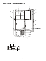
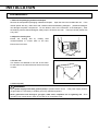
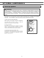
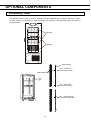
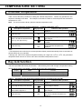
INSTRUCTION MANUAL
Ultra-Low Temperature Freezer
MDF-U32V
Note:
1. No part of this manual may be reproduced in any form without the expressed written
permission of SANYO.
2. The contents of this manual are subject to change without notice.
3. Please contact SANYO if any point in this manual is unclear or if there are any
inaccuracies.
SANYO Electric Biomedical Co., Ltd.
All rights reserved.
Printed in Japan.
CONTENTS
PRECAUTIONS FOR SAFE OPERATION
P. 2
CAUTIONS FOR USAGE
P. 6
ENVIRONMENTAL CONDITIONS
P. 7
FREEZER COMPONENTS
P. 8
Control panel and keypad
P.10
INSTALLATION
Installation site
P.11
Installation
P.12
OPTIONAL COMPONENTS
Temperature recorder
P.13
Back-up system
P.14
Inventory rack
P.15
START-UP OF UNIT
P.16
TEMPERATURE SETTING
Chamber temperature
P.17
Key lock function
P.17
Alarm temperature setting
P.18
ALARMS & SAFETY FUNCTIONS
P.19
SETTING OF ALARM RESUME TIME
P.20
REMOTE ALARM TERMINAL
P.21
MONITOR OF FREEZER STATUS
P.22
CHANGE OF COMPRESSOR DELAY TIME
P.23
ROUTINE MAINTENANCE
Cleaning of cabinet
P.24
Cleaning of condenser filter
P.24
Defrosting of inside wall
P.25
TROUBLESHOOTING
P.26
DISPOSAL OF UNIT
P.26
RECYLCE OF RECHARGEABLE BATTERY
P.27
SPECIFICATIONS
P.28
PERFORMANCE
P.28
SAFETY CHECK SHEET
P.29
1
PRECAUTIONS FOR SAFE OPERATION
It is imperative that the user complies with this manual as it contains
important safety advice.
Items and procedures are described so that you can use this unit correctly and safely.
If the precautions advised are followed, this will prevent possible injury to the user and
any other person.
Precautions are illustrated in the following way:
WARNING
Failure to observe WARNING signs could result in a hazard to personnel
possibly resulting in serious injury or death.
CAUTION
Failure to observe CAUTION signs could result in injury to personnel and
damage to the unit and associated property.
Symbol shows;
this symbol means caution.
this symbol means an action is prohibited.
this symbol means an instruction must be followed.
Be sure to keep this manual in a place accessible to users of this unit.
< Label on the unit >
This mark is labeled on the cover in which the electrical components of high voltage are
enclosed to prevent the electric shock.
The cover should be removed by a qualified engineer or a service personnel only.
WARNING
As with any equipment that uses CO2 gas, there is a likelihood of oxygen depletion in the vicinity of the
equipment. It is important that you assess the work site to ensure there is suitable and sufficient
ventilation. If restricted ventilation is suspected, then other methods of ensuring a safe environment must
be considered. These may include atmosphere monitoring and warning devices.
2
PRECAUTIONS FOR SAFE OPERATION
WARNING
Do not use the unit outdoors. Current leakage or electric shock may result if the unit is exposed to
rain water.
Only qualified engineers or service personnel should install the unit.
unqualified personnel may cause electric shock or fire.
The installation by
Install the unit on a sturdy floor. If the floor is not strong enough or the installation site is not
adequate, this may result in injury from the unit falling or tipping over.
Never install the unit in a humid place or a place where it is likely to be splashed by water.
Deterioration of the insulation may result which could cause current leakage or electric shock.
Never install the unit in a flammable or volatile location. This may cause explosion or fire.
Never install the unit where acid or corrosive gases are present as current leakage or electric
shock may result due to corrosion.
Use a dedicated power source as indicated on the rating label attached to the unit.
Connect the power supply plug to the power source firmly. Improper insertion may cause a heat
or ignition.
Use a power supply outlet with ground (earth) to prevent electric shock. If the power supply
outlet is not grounded, it will be necessary to install a ground by qualified engineers.
Never ground the unit through a gas pipe, water main, telephone line or lightning rod. Such
grounding may cause electric shock in the case of an incomplete circuit.
Never store volatile or flammable substances in this unit if the container cannot be sealed. This
may cause explosion or fire.
Never store corrosive substances in this unit if the container cannot be sealed. This may lead to
damage to the inner components or electric parts.
Do not insert metal objects such as a pin or a wire into any vent, gap or any outlet for inner air
circulation. This may cause electric shock or injury by accidental contact with moving parts.
Use this unit in safe area when treating the poison, harmful or radiate articles. Improper use
may cause bad effect on your health or environment.
Disconnect the power supply to the unit prior to any repair or maintenance of the unit in order to
prevent electric shock or injury.
3
PRECAUTIONS FOR SAFE OPERATION
WARNING
Ensure you do not inhale or consume medication or aerosols from around the unit at the time of
maintenance. These may be harmful to your health.
Never splash water directly onto the unit as this may cause electric shock or short circuit.
Never disassemble, repair, or modify the unit yourself. Any such work carried out by an
unauthorized person may result in fire or injury due to a malfunction.
Disconnect the power supply plug if there is something wrong with the unit.
abnormal operation may cause electric shock or fire.
Continued
If the unit is to be stored unused in an unsupervised area for an extended period, ensure that
children do not have access and that doors cannot be closed completely.
The disposal of the unit should be accomplished by appropriate personnel. Remove doors to
prevent accidents such as suffocation.
Ventilate the room air when using the carbon dioxide gas for the back-up system. The CO2
density level in the air could rise and may be harmful to humans.
Prepare a safety check sheet when you request any repair or maintenance for the safety of service
personnel.
CAUTION
Select a level and sturdy floor for installation. This precaution will prevent the unit from tipping.
Improper installation may result in water spillage or injury from the unit tipping over.
Connect the unit to a power source as indicated on the rating label attached to the unit. Use
of any other voltage or frequency other than that on the rating label may cause fire or electric shock.
Never bind, process, or step on the power supply cord, or never damage or break the power
supply plug. Do not use the supply plug if its cord is loose. This may cause fire or electric
shock.
When removing the plug from the power supply outlet, grip the power supply plug, not the cord.
Pulling the cord may result in electric shock or fire by short circuit.
Do not touch any electrical parts such as the power supply plug or any switches with a wet hand.
This may cause electric shock.
4
PRECAUTIONS FOR SAFE OPERATION
CAUTION
Check the setting when starting up of operation after power failure or turning off of power
switch. The stored items may be damaged due to the change of setting.
Do not put a container with water or heavy articles on the unit. It may cause injury if the articles
fall. Current leakage or electric shock may be resulted form the deterioration of insulation by spilled
water.
Do not climb onto the unit or do not put articles on the unit. This may cause injury by tipping or
damage to the unit.
Always hold the handle when closing the door. This will reduce the likelihood of a trapped finger.
Do not put glass bottles or cans into the compartment since they may be broken by frozen
contents and cause injury.
Do not touch the stored items with bare hand.
naked hand may cause frostbite.
Do not lean on the door.
Handing frozen contents or the inside walls with
This may cause injury if the unit tips over or door is broken.
Put on gloves at the time of maintenance to prevent injury by the edge or corner of the
components.
Check the filter mentioned in this manual and clean it as necessary.
temperature rise or failure.
A dusty filter may cause
Do not touch the condenser directly when the filter is removed for cleaning.
by hot surface.
This may cause injury
Disconnect the power supply plug before moving the unit. Take care not to damage the power
cord. A damaged cord may cause electric shock or fire.
Be careful not to tip over the unit during movement to prevent damage or injury.
Disconnect the power plug when the unit is not used for long periods. Keeping the connection may
cause electric shock, current leakage, or fire due to the deterioration of insulation.
Do not put the packing plastic bag within reach of children as suffocation may result.
5
CAUTIONS FOR USAGE
1. When the first start-up or start-up after no use of long period, the warning device may not operate,
because its Ni-MH battery has completely discharged. This does not denote a malfunction. In this
case, continue to operate the unit for about 3 hours, then push the test switch to check if the warning
device operates. To fully recharge the completely discharged battery, the unit has to be operated for
about 2 days.
2. In the case of high ambient temperature, the cabinet front may heat up after the freezer starts to
operate first. However, this does not denote a malfunction. It is due to the hot gas piped around the
unit frame to prevent condensation around the cabinet.
3. Cool down the freezer chamber sufficiently before storing materials and put the materials in a small
batch to reduce the temperature rise.
4. The digital thermometer of this ultra-low temperature freezer is designed to display the temperature of
the center part of the freezing compartment. The thermometer sometimes displays a temperature a little
bit higher than the actual temperature of the center part depending on the amount or arrangement of
stored items.
5. An access port to take out the measuring cable in the case is provided on the back wall and right
bottom of the freezer. Be sure to replace the cap and thermal insulation after taking out of the cable, or
the chamber temperature cannot complete down, and frost may accumulate outside the port
surroundings.
6. Always open and close the door gently. Rough operation may lead fall down of stocked items,
incomplete closing, or damage of door gasket.
7. Check and rectify the problem as soon as possible when the alarm lamp is light and buzzer is activated.
Refer to table 5 on page 19 for the alarm.
8. Do not use brushes, acids, thinners, powdered soap or hot water for cleaning the freezer. Polishing
powders or hot water can deteriorate the painted surfaces or cause deformation, discoloration or
degeneration of plastic or rubber components. Be especially careful not to wipe plastic or rubber parts
with volatile solvents such as benzine. Wipe off a diluted neutral dishwashing detergent completely with
a wet cloth when it is used.
9. The frost will be built up on the chamber wall and inner door during operation. Use a scraper provided
with the freezer or equivalent tool to remove the frost. The inner door is hard to be opened when a large
amount of frost is built up on it. In this case, remove the frost by detaching the inner door as shown in
page 25.
10. There are pipelines for cooling behind the walls. Do not defrost inside walls using a knife, ice pick,
or screw driver. Be careful not to damage the walls or to make a hole on the walls as this could cause a
failure of the freezer. Also, take care not to drop a heavy item or anything with sharp edge on the
bottom of the chamber.
11. Because of a large freezer, the following facilities are needed; a dedicated power outlet of more than
15A capacity, a motor breaker of more than 15A or a general-purpose breaker of more than 30A. Do not
use a branched socket for power source as it may cause unstable voltage and result in a failure of the
unit. Always use a dedicated power outlet. For details, consult a Sanyo sales representative or an
electrician.
6
ENVIRONMENTAL CONDITIONS
This equipment is designed to be safe at least under the following conditions (based on the IEC-1010-1):
1. Indoor use;
2. Altitude up to 2000 m;
3. Ambient temperature 5oC to 40oC
4. Maximum relative humidity 80% for temperature up to 31oC decreasing linearly to 50% relative
humidity at 40oC;
5. Mains supply voltage fluctuations not to exceed ±10% of the nominal voltage;
6. Other supply voltage fluctuations as stated by the manufacturer;
7. Transient overvoltages according to Installation Categories (Overvoltage Categories) II; For mains
supply the minimum and normal category is II;
8. Pollution degree 2 in accordance with IEC 664.
7
FREEZER COMPONENTS
5
8
1
11
6
3
2
4
5(inside)
12
10
9
7
13
15(inside)
14
17
16
18
8
FREEZER COMPONENTS
1. Outer door:
2. Handle:
To open the door, grip the handle. On closing, lock the door latch completely.
Always grip this handle to open and close the outer door.
3. Door latch:
Always lock the latch when the outer door is closed.
4. Magnetic door gasket:
This provides a tight door seal and prevents cold air leak. Keep clean.
5. Access port (rear and bottom): This is used for leading a cable and sensor of a measuring
equipment, or nozzle of back-up system to chamber.
6. Inner door: The operation of the inner door should be quick to minimize the temperature rise in
chamber. Lock the door latch completely when the door is closed. The door is removable for cleaning
or defrosting. See page 25 “Routine maintenance”.
7. Lock: Turn clockwise to 180o with a key and the outer door is securely locked.
8. Control panel (on the upper front of the door): Used for temperature setting and indication of
operating status is displayed on the panel. See page 10 for details.
9. Caster: 4 casters are provided to facilitate moving of the cabinet. For the installation, adjust the
leveling foot so that the front 2 casters cannot contact with the floor.
10. Leveling foot: The height of the freezer can be adjusted by this screw type foot. Keep the unit in
level at the installation.
11. Fixture (on back side): 2 fixtures serve as spacers between the cabinet and wall and also serve as
hooks to fix the unit. See page 12 “Installation”.
12. Air intake vent (grille): Do not block this vent to keep the proper cooling performance.
13. Power switch: This is for turning ON/OFF the power to the unit. ON – “I” OFF – “○”
14. Space for temperature recorder: An automatic temperature recorder (optional component) can be
attached here. See page 13 “Temperature recorder”.
15. Condenser filter (behind the grille): This filter prevents the dust from accumulating on the
condenser. The dusty filter may cause failure of refrigerating device. Clean the filter once a month.
See page 24 “Routine maintenance” for the cleaning.
16. Battery switch: This is a switch for a battery for power failure alarm. Normally, turn on this switch.
Be sure to turn off this switch if the freezer is not in operating for the long period.
17. Remote alarm terminal: This is used to notice an alarm condition of the unit to remote location.
Refer to page 21 “Remote alarm terminal”.
18. Space for optional component:
9
FREEZER COMPONENTS
Control panel and keypad
5
11
TEMPERATURE
ULTRA
LOW
10
8 6
9
BATTERY
FILTER
STATUS
ALARM
DOOR
BUZZER
ALARM
TEST
STATUS
SET
1
7
12
2
3
4
1. Buzzer stop key (BUZZER): To silence the audible alarm under alarm condition, press this key.
The buzzer during alarm test cannot be silenced by this key.
2. Set key (SET): Temperature setting mode is led by pressing this key and the changeable digit is
flashed. By pressing this key again, the setting is memorized. The set mode returns to the
temperature display mode automatically when 90 seconds has passed without any key operation. Refer
to page 17 for details.
3. Digit shift key (
): Pressing this key in the setting mode causes the changeable digit to shift. Key
lock is available by pressing this key for more than 5 seconds in the temperature display mode. Refer to
page 17 for details.
4. Numerical value shift key (
): Pressing this key in the setting mode causes the numerical value to
shift. “ON-OFF” of key lock can be selected by pressing this key in the key lock mode. By pressing this
key for more than 5 seconds in the temperature display mode leads setting mode for alarm temperature
and alarm resume time. Refer to page 18 and 20 for details respectively.
5. Digital temperature indicator:
temperature.
6. Alarm lamp (ALARM):
This indicator shows the present chamber temperature or set
This lamp is flashed during alarm condition.
7. Alarm test key (ALARM TEST): To check the alarm system. Pressing this key with the battery
switch ON gets the alarm lamp to flash, the remote alarm to operate, and the buzzer to sound.
8. Door check lamp (DOOR):
This lamp lights when the door is open.
9. Filter check lamp (FILTER): This lamp lights when the excessive dust is accumulated on the
condenser filter. When this lamp lights, clean the condenser filter following the procedure on page 24.
10. Battery check lamp (BATTERY): This lamp flickers to recommend the battery replacement. For
the replacement, consult Sanyo sales representative or agent.
11. Status monitor lamp (STATUS): This lamp lights when environmental condition or status gets
worse or the unit is out of normal operation.
12. Status key (STATUS): By pressing this key in the event of the status monitor lamp ON, the status
code is displayed on the temperature indicator. This key is not effective when the freezer is running
normally. See page 22 for details.
10
INSTALLATION
Installation site
To operate this unit properly and to obtain maximum performance, install the unit in a location with the
following conditions:
1. A location not subjected to direct sunlight
Installation in a location subjected to direct sunlight may lead to inadequate cooling.
2. A location with adequate ventilation
Leave at least 10 cm around the unit for ventilation. Poor ventilation will result in a reduction of the
refrigeration capacity.
3. A location away from heat generating sources
Avoid installing the unit near heat-emitting appliances such as gas ranges or stoves. Heat can cause
inefficient refrigeration.
4. A location with a sturdy and level floor
WARNING
Install the unit on a sturdy floor. If the floor is not strong enough or the installation site is not
adequate, this may result in injury from the unit falling or tipping over.
Select a level and sturdy floor for installation. This precaution will prevent the unit from tipping.
Improper installation may result in water spillage or injury from the unit tipping over.
5. A location not prone to high humidity
WARNING
Do not use the unit outdoors. Current leakage or electric shock may result if the unit is exposed to
rain water.
Never install the unit in a humid place or a place where it is likely to be splashed by water.
Deterioration of the insulation may result which could cause current leakage or electric shock.
6. A location without flammable or corrosive gas
WARNING
Never install the unit in a flammable or volatile location. This may cause explosion or fire.
Never install the unit where acid or corrosive gases are present as current leakage or electric shock
may result due to corrosion.
11
INSTALLATION
Installation
1. Remove the packaging materials and tapes
Remove all transportation packaging materials and tapes. Open the doors and ventilate the unit. If the
outside panels are dirty, clean them with a diluted neutral dishwashing detergent. (Undiluted detergent
can damage the plastic components. For the dilution, refer to the instruction of the detergent.) After
the cleaning with the diluted detergent, always wipe it off with a wet cloth. Then wipe off the panels with
a dry cloth.
2. Adjust the leveling foot
Extend the leveling feet by rotating them
counterclockwise to contact them to the floor.
Ensure the unit is level.
Leveling foot
3. Fix the unit
Two fixtures are attached to the rear of the frame.
Fix the frame to the wall with these fixtures and rope
or chain.
Fixture
4. Ground (earth)
WARNING
Use a power supply outlet with ground (earth) to prevent electric shock. If the power supply outlet is
not grounded, it is necessary to install a ground by qualified engineers.
Never ground the unit through a gas pipe, water main, telephone line or lightning rod. Such
grounding may cause electric shock in the case of an incomplete circuit.
12
OPTIONAL COMPONENTS
Temperature recorder
An automatic temperature recorders is available for this freezer as the optional component. The type of
the recorder is MTR-G85.
Following shows the attachment procedure.
1. Remove four screws on the front panel and take it off.
By removing four screws, take off the left side panel.
Then take off the cover for the recorder mounting space
by removing four screws. (Fig. 1)
Fig. 1
2. As shown in the Fig. 2, insert the temperature
recorder to the mounting space and fix it to the back
side of the front panel by using the recorder fixture
enclosed with the recorder.
Fig. 2
3. Take off the recorder sensor cover in the chamber
(bottom left side) by removing two screws. Then
remove the rubber cap and insulation covering the
sensor port. (Fig. 3)
4. As shown in the Fig. 4, pass the recorder sensor
through the sensor guide pipe from the front to the back.
The sensor guide pipe is provided on the upper left side
of the base compartment.
5. Take out the recorder sensor from the guide pipe at
the back side and pass the sensor to the chamber
through the access port. (Fig. 5)
Fig. 4
6. Attach the recorder sensor on the sensor cover with
the enclosed clips. Seal the sensor port with a silicon
and replace the recorder sensor cover. Fix the cover
to the inside wall. (Fig. 6)
7. Remove the connector cover. Connect the recorder
connector at the end of the power cord with the white
connector on the left of the base compartment. Bind
the extra lead wire of the sensor with a nylon clip on the
back of the recorder. (Fig. 7)
Sensor guide pipe
Fig. 3
Fig. 5
Fig. 6
connector
8. Replace the left side panel and front panel and fix
them with screws.
Fig. 7
13
OPTIONAL COMPONENTS
Back-up system
WARNING
As with any equipment that uses CO2 gas, there is a likelihood of oxygen depletion in the vicinity
of the equipment. It is important that you assess the work site to endure there is suitable and
sufficient ventilation. If restricted ventilation is suspected, then other methods of ensuring a
safe environment must be considered. These may include atmosphere monitoring and warning
devices.
This freezer can be provided with a back-up system (CVK-UB2) which is available as an optional
component. For the installation, refer to the instruction manual enclosed with the system.
1. Switch of back-up system (BACKUP)
When turning on the system, the lamp is brightened.
This means that the system is ready. To stop the
operation of the system, turn off this switch.
1
2
2. Test switch (TEST)
This switch is for checking the operation of back-up
system. Pressing this switch is resulted in the release
of liquid carbon dioxide without system operation.
3. Temperature setting knob (TEMP. SET)
With this knob, set the temperature at which the system
is operated. The effective set temperature range is
between -50oC and -70oC.
14
3
OPTIONAL COMPONENTS
Inventory rack
The optional inventory rack is useful to store the precious materials in the chamber effectively. When
the rack is used, it is necessary to adjust the height of the shelves. Set the shelf support as shown in
the figure below.
IR-216U
IR-220U
Shelf support
No. 7 under first
screw from the top
Shelf stopper
No. 1 under forth
screw from the top
No. 1 under second
screw from the bottom
15
START-UP OF UNIT
Follow the procedures for the initial and consequent operations of the unit.
1. Connect the power cord to the dedicated outlet having appropriate rating with the chamber empty, and
turn on the power switch on the freezer.
2. Turn off the switch of the back-up system (optional component) if it is installed.
3. Check that the battery switch is ON.
4. The audible alarm may activated. In this case, press the buzzer stop key (BUZZER) to silence the
alarm.
5. Set the desired chamber temperature.
See page 17 for the temperature setting.
6. Check that the chamber temperature reaches the desired temperature.
7. Turn on the switch of back-up system (optional component) if it is installed.
8. Make sure that the alarm lamp lights and the buzzer sounds by pressing the alarm test key.
9. After confirming the above, you can put articles into the freezer chamber in a small batch to prevent the
temperature rise.
16
TEMPERATURE SETTING
Chamber temperature
Table 1 shows the basic procedure for setting the chamber temperature. Perform key operations in the
sequence indicated in the table. The example in the table is based on the assumption that the desired
temperature is -75oC.
Note: The unit is set at the factory that the chamber temperature -80oC.
Table 1.
1
Chamber temperature -75oC)
Basic operation sequence (Example:
Description of operation
Turn the power switch ON.
2
Press SET key.
3
Set to -75 with the numerical value
shift key and digit shift key.
4
Press SET key.
Key operated
---SET
SET
Indication after operation
The current chamber temperature is
displayed.
The second digit is flashed.
When pressed, the figure of settable
digit changes.
When pressed, the settable digit
is shifted.
Set temperature is memorized and the
current chamber temperature is
displayed.
Note:
• The temperature set mode returns to the temperature display mode automatically when 90 seconds has
passed without any key operation.
• Although the value of the chamber temperature setting can range from -50oC to -90oC, the guaranteed
temperature when there is no load is -85oC when the ambient temperature is 30oC.
Key lock function
This unit is provided with the key lock function. When the key lock is ON, change of temperature setting
through the key pad is not available. The key lock is set in OFF at the factory.
Display
Table 2.
Mode
Function
L 0
Key lock is OFF
Enable to change of temperature setting
L 1
Key lock is ON
Disable to change of temperature setting
Procedure for key lock setting (change from key lock OFF to key lock ON)
Description of operation
1
Key operated
----
Indication after operation
The current chamber temperature is
displayed.
2
Press digit shift key for 5 seconds.
The first digit is flashed.
3
Press numerical value shift key
and scroll the figure to 1.
4
Press SET key.
When pressed, the figure of settable
digit changes.
The key lock is set to ON.
The current chamber temperature is
displayed.
SET
17
TEMPERATURE SETTING
Alarm temperature setting
This unit is provided with the high and low temperature alarm and the temperature at which the alarm is
activated is changeable.
The following procedure shows the setting of alarm temperature according to the condition below:
High temperature alarm: activates at the temperature 5oC higher than the set temperature
Low temperature alarm: activates at the temperature 5oC lower than the set temperature
Note:
The alarm temperature is set at the factory 10oC higher and lower than the set temperature.
The available range of alarm temperature is between 5oC and 20oC higher or lower than the set
temperature.
Table 3.
Procedure for setting high temperature alarm
Description of operation
1
2
3
---Press numerical value shift key for
about 5 seconds.
Press numerical value shift key
and scroll the figure to 1.
4
Press SET key.
5
Scroll the figure to 005 by using
digit shift key and numerical value
shift key
6
Press SET key.
Table 4.
1
3
Indication after operation
The current chamber temperature is
displayed.
The first digit is flashed.
The first digit is flashed.
SET
SET
The first digit is flashed.
When pressed, the figure of settable
digit changes.
When pressed, the changeable digit
moves.
Alarm temperature is memorized and
the current chamber temperature is
displayed.
Procedure for setting low temperature alarm
Description of operation
2
Key operated
Key operated
----
Press numerical value shift key for
about 5 seconds.
Press numerical value shift key
and scroll the figure to 2..
4
Press SET key.
5
Scroll the figure to -05 by using
digit shift key and numerical value
shift key
6
Press SET key.
Indication after operation
The current chamber temperature is
displayed.
The first digit is flashed.
The first digit is flashed.
SET
SET
18
The first digit is flashed.
When pressed, the figure of settable
digit changes.
When pressed, the changeable digit
moves.
Alarm temperature is memorized and
the current chamber temperature is
displayed.
ALARMS & SAFETY FUNCTIONS
This unit has the alarms and safety functions shown in Table 5, and also self diagnostic functions.
Table 5.
Alarms and safety functions
Alarm & Safety
High temperature
alarm
Low temperature
alarm
Power failure alarm
Filter check
Battery check
Auto-return
Key lock
Situation
If the chamber temperature is higher
than the temperature at which the
high temperature alarm is activated.
If the chamber temperature is lower
than the temperature at which the
low temperature alarm is activated.
When the power to the unit is
disconnected.
When the condenser filter is clogged.
When about 2.8 years has passed with
power switch ON.
When there is no key pressing in
each setting mode for 90 seconds.
Indication
Battery switch
check
Safety operation
ALARM lamp is flashed.
Temperature indicator is
flashed.
Intermittent tone with
15 minutes delay.
Remote alarm with 15
minutes delay.
ALARM lamp is flashed.
Intermittent tone
Remote alarm.
Filter check lamp lights.
-----
-----
Battery check lamp lights.
-----
-----
Chamber temperature is
displayed.
-----
When the key lock is “ON”.
-----
ALARM lamp is flashed.
E01 and chamber temp. are
displayed alternately.
ALARM lamp is flashed.
If the thermal sensor is short-circuited. E02 and chamber temp. are
displayed alternately.
ALARM lamp is flashed.
If the cascade sensor is disconnected. E03 and chamber temp. are
displayed alternately.
ALARM lamp is flashed.
If the cascade sensor is short circuited. E04 and chamber temp. are
displayed alternately.
ALARM lamp is flashed.
If the filter sensor is disconnected.
E05 and chamber temp. are
displayed alternately.
ALARM lamp is flashed.
If the filter sensor is short-circuited.
E06 and chamber temp. are
displayed alternately.
ALARM lamp is flashed.
If the ambient temperature sensor is
E07 and chamber temp. are
disconnected.
displayed alternately.
ALARM lamp is flashed.
If the ambient temperature sensor is
E08 and chamber temp. are
short-circuited.
displayed alternately.
When the battery switch is OFF during ALARM lamp is flashed.
alarm test.
E09 is flashed.
If the thermal sensor is disconnected.
Sensor abnormality
Buzzer
----Intermittent tone
Intermittent tone
Finishing of each
setting mode.
Change of setting is
disable.
Remote alarm.
Unit keeps continuous
running.
Remote alarm.
Unit keeps continuous
running.
Intermittent tone
Remote alarm.
Unit keeps running.
Intermittent tone
Remote alarm.
Unit keeps running.
Intermittent tone
Remote alarm.
Intermittent tone
Remote alarm.
Intermittent tone
Remote alarm.
Intermittent tone
Remote alarm.
-----
-----
Note:
• When the operation is started in high ambient temperature, the filter check lamp is sometimes flashed.
In this case, the lamp is off automatically when the chamber temperature is getting lower.
• The freezer resumes the operation after power failure with the temperature setting before power failure
as the chamber temperature setting and alarm temperature setting are memorized in the volatile memory.
• The chamber temperature is displayed for 5 seconds by pressing BUZZER key during power failure
alarm. Then the buzzer is silenced. The ALARM lamp keeps flashing.
19
SETTING OF ALARM RESUME TIME
The alarm buzzer is silenced by pressing BUZZER key on the control panel during alarm condition (The
remote alarm is not silenced).
The buzzer will be activated again after certain suspension if the alarm condition is continued. The
suspension time can be set by following the procedure shown in the Table 6 below.
The example in the table is based on the assumption that the desired duration is 20 minutes.
Note: The duration is set in 30 minutes at the factory.
Table 6.
Setting procedure for alarm resuming time (change from 30 minutes to 20 minutes)
Description of operation
1
Key operated
The current chamber temperature is
displayed.
----
2
Press digit shift key for 5 seconds.
3
Set the figure to F25 with the digit
shift key and numerical value shift
key.
4
Press SET key.
5
Set the figure to 020 with the
numerical value shift key.
6
Press SET key.
Indication after operation
The first digit is flashed.
The settable digit is shifted.
When pressed, the figure of settable
digit changes.
SET
The current reset time is displayed.
The middle digit is flashed.
When pressed, the figure of settable
digit changes.
SET
The setting is memorized and
the current chamber temperature is
displayed.
• The settable alarm resume time is 10, 20, 30, 40, 50, or 60 minutes (The setting is 010, 020, 030, 040,
050, or 060). The buzzer would not reset if the reset time is set in 000.
• It is recommended to set the alarm resume time when the freezer is not under alarm condition. The
setting during alarm condition is effective on the next alarm condition.
• The setting cannot be changed during power failure.
• The remote alarm during power failure or buzzer and remote alarm during alarm test cannot be
silenced.
• The set mode returns to the temperature display mode automatically when 90 seconds has passed
without any key operation. In this case, any setting before pressing SET key is not memorized.
20
REMOTE ALARM TERMINAL
The terminal of the remote alarm is installed at the lower left side of the unit. The alarm is outputted
from this terminal. Contact capacity is DC 30V, 2 A.
Contact output:
between COM. and N.O.
between COM. and N.C.
At normal
Open
Close
At abnormal
Close
Open
Note:
The alarm is actuated when the power cord is disconnected from the outlet or the power switch is OFF.
REMOTE ALARM
N.O. COM N.C.
MAX DC30V 2A
21
MONITOR OF FREEZER STATUS
The freezer has a function to monitor the running status of the unit as shown in table 7 below. This is to
notice the running status getting worse (not failure).
1. The STATUS lamp is lit when one of the running status shown in table 7 is detected.
2. The S code (--X, X: 1 to 3) is displayed on the temperature indicator by pressing STATUS key when
the STATUS lamp is lit.
3. Pressing the STATUS key again causes current chamber temperature display on the temperature
indicator. (The indication returns to the chamber temperature display automatically when no key is
operated for 90 seconds.)
Table 7.
Monitor of running status
Kind of
function
Status
Notice of
abnormal
ambient
temperature
When the ambient
temp. is over about
35oC or lower than
about 0oC.
Notice of low
voltage
When the power
source voltage is
less than about 97V
when the rated
voltage is 115V or
less than about 195V
when the rated
voltage is between
220 and 240V.
Notice of
overload
condition
When the running
rate of refrigerating
Circuit is more than
usual.
Indication
If this status
continues
STATUS lamp
lights.
“--1” is displayed.
Decrease of cooling
performance or
durability of
refrigerating circuit.
Recheck of
air-conditioning of
installed site.
STATUS lamp
lights.
“--2” is displayed.
Abnormal heat at
power supply outlet
or degrade of
starting performance
of refrigerating
circuit
Use of dedicated
power source.
Decrease of cooling
performance or
durability of
refrigerating circuit.
1. This is likely
happened when
large amount of
materials are stored.
2. Check of ambient
temp., voltage, and
sealing of
outer/inner door.
STATUS lamp
lights.
“--3” is displayed.
Remedy
Note:
• The S code displayed on the temperature indicator is changed every a few seconds if two or three
status shown in the above table are detected at the same time. (--1 ⇒ --2 ⇒ --3 ⇒ --1 repeated)
• The monitoring function has no buzzer operation and no safety operation.
• In the case of multiple indication of S code, follow the remedy for each status.
22
CHANGE OF COMPRESSOR DELAY TIME
The delay time of high and low stage side compressor can be changed to reduce the load on the power
line and to facilitate the start-up (reset) of the freezer after power failure.
The example in the table is based on the assumption that the delay time is changed to 4 minutes.
(The delay time is set in 2 minutes at the factory.)
Note:
• The delay time should be same for high stage side and low stage side compressors.
• The setting range for delay time is between 2 and 15 minutes. The cool down of chamber temperature
may be slow when the setting of delay time is over 5 minutes, depending on the installation environment.
There is no need changing the delay time when the capacity of power source is enough.
Table 8.
Changing procedure for delay time (change from 2 minutes to 4 minutes)
Description of operation
1
Key operated
Indication after operation
The current chamber temperature is
displayed.
----
2
Press numerical value shift key for
5 seconds.
The first digit is flashed.
3
Set the figure to F05 with the
numerical value shift key.
When pressed, the figure of settable
digit changes.
4
Press SET key.
5
Set the figure to 004 with the
numerical value shift key.
6
Press SET key.
SET
The current delay time is displayed.
The first digit is flashed.
When pressed, the figure of the first
digit changes.
SET
The delay time is memorized and
the current chamber temperature is
displayed.
• The compressor starts to operate with the delay time set by the above procedure at the time of power
on or after power failure. For the low stage side compressor, however, its start up may be behind the
delay time because the compressor is affected by the chamber temperature and temperature of cascade
condenser installed in the freezer.
23
ROUTINE MAINTENANCE
WARNING
Always disconnect the power supply to the unit prior to any repair or maintenance of the unit in
order to prevent electric shock or injury.
Ensure you do not inhale or consume medication or aerosols from around the unit at the time of
maintenance. These may be harmful to your health.
Cleaning of cabinet
• Clean the unit once a month. Regular cleaning keeps the unit looking new.
• Use a dry cloth to wipe off small amounts of dirt on the outside and inside of the unit and all accessories.
If the outside panels are dirty, clean them with a diluted neutral dishwashing detergent. (Undiluted
detergent can damage the plastic components. For the dilution, refer to the instruction of the detergent.)
After the cleaning with the diluted detergent, always wipe it off with a wet cloth. Then wipe off the
cabinet or accessories with a dry cloth.
• Never pour water onto or into the unit. Doing so can damage the electric insulation and cause failure.
• The compressor and other mechanical parts are completely sealed. This unit requires absolutely no
lubrication.
• Check the back-up system by pressing TEST switch once a month if it is installed.
• Remove the frost or ice on the chamber wall and clean the condenser filter once a month.
Cleaning of condenser filter
This unit is provided with the filter check lamp on the control panel. Clean the filter when this lamp lights.
Clean the filter once a month even if the check lamp is not on since a clogged filter may cause shorter
compressor life as well as the poor cooling.
Clean the filter by the procedure below.
1. Open the grille by pulling it to you as shown in the
figure.
2. Take out the condenser filter.
3. Wash the filter with water.
4. Replace the filter and the grille.
5. Check that the filter check lamp is off in the event the
check lamp was ON.
WARNING
Do not touch the condenser directly when the filter is removed for cleaning.
hot surface.
24
This may cause injury by
ROUTINE MAINTENANCE
Defrosting of inside wall
The frost is built at the upper portion of the chamber and inner door. The excessive frost possibly make
some gap between the cabinet and door gasket, which may cause poor cooling. Remove the frost on
the inner door with a scraper enclosed with the unit. Following shows the procedure for removing the
chamber frost.
Note: For removing the frost, do not use a tool with sharp edge such as a knife or a screw driver.
1. Turn off the back-up system if applicable.
2. Take out and transfer all the contents to another freezer or a container which is refrigerated by liquid
carbon dioxide or dry ice.
3. Turn off the power switch of the freezer.
4. Open the outer door and inner door. Remove the
inner door by lifting up as shown in the figure.
5. Leave the freezer as it is.
6. The water accumulated on the bottom of the
chamber should be wiped up with a dry cloth.
7. After cleaning the chamber and inner door, replace
the inner door and start up the unit according to the
procedure on page 16.
8. Put back the articles into the sufficiently cooled
freezer compartment.
9. Turn on the back-up system if it is provided.
25
TROUBLESHOOTING
If the unit malfunctions, check out the following before calling for service.
The chamber is not cooled at all
1. The circuit breaker of power source is active.
2. The voltage is too low. (The status code “--2” is displayed. See page 22.) In this case, call an
electrician.
3. The power switch is not ON.
4. The large amount of articles (load) is stored in the chamber at one time. (The status code “--3” is
displayed. See page 22.)
The cooling is poor
1. The ambient temperature is too high. (The status code “--1” is displayed. See page 22.)
2. The latch of inner door is not closed completely. The outer door is not closed firmly.
(The frost or ice between the cabinet and door gasket possibly prevents door seal.)
3. The air intake vent is blocked.
4. The condenser filter is clogged. Always clean the filter when the filter check lamp is lit.
5. The set temperature is not inputted properly.
6. The freezer is not away from the direct sunlight.
7. There is any heating source near the freezer.
8. A rubber cap and insulation for the access port are not set correctly.
9. You put too many unfrozen articles into the freezer compartment.
Alarm test key cannot actuate the alarm
The alarm is activated only when the power switch is ON.
1. The nickel-metal-hydride battery has been discharged entirely. In this case, operate the freezer for
about 3 hours and depress the alarm test key again. Entirely discharged cell requires about 2 days’
operation of the freezer.
2. When only the buzzer or only the alarm is actuated by the alarm test key, the unactuated part is out of
order, and must be replaced.
Noise
1. The freezer is not installed on the sturdy floor.
2. The freezer is not leveled with the leveling feet.
3. There is anything touching the frame.
4. The freezer is in the status immediately after start up.
The unit sometimes causes a noise when the chamber temperature is high due to the large load. The
noise gets less and less accompanying with the cooling of the chamber.
Back-up test switch does not operate normally (if the back-up system is provided)
1. The liquid carbon dioxide tank is empty.
2. The valve of the carbon dioxide tank is not opened.
3. The ambient temperature is too high. In this case, move the tank to a cool location.
Inquire at liquid carbon dioxide suppliers about its installation, removal, adjustment, and examination.
DISPOSAL OF UNIT
WARNING
If the unit is to be stored unused in an unsupervised area for an extended period ensure that children
do not have access and doors cannot be closed completely.
The disposal of the unit should be accomplished by appropriate personnel. Always remove
doors to prevent accidents such as suffocation.
26
RECYCLE OF RECHARGEABLE BATTERY
The unit contains a rechargeable battery. The battery is recyclable. At the end
of it’s useful life, check with you local solid officials option or proper disposal.
1. Location of a nickel-metal-hydride battery
This unit is provided a nickel-metal-hydride battery for the power failure warning device. The battery is
located in the electrical box inside the cover on the lower left side. (Fig. 1)
The high voltage components are enclosed in the electrical box. The cover should be removed
by a qualified engineer or a service personnel only to prevent the electric shock..
2. Removal of nickel-metal-hydride battery
1) Turn off the power switch and disconnect the power supply plug.
2) As shown in the Fig. 2, remove 7 screws fixing the side cover with a screw driver and remove the side
cover..
3) Remove 4 screws fixing the electrical box cover with a screw driver. (Fig. 3)
4) Disconnect the battery connector and remove 2 screws fixing the battery mounting plate. (Fig. 4)
5) Take out the battery.
6) Follow the procedure for recycling or proper disposal.
Side cover
Electrical box
Fig. 1
Fig. 2
Electrical box cover
Battery
mounting plate
Fig. 3
27
Fig. 4
SPECIFICATIONS
Name
Ultra-Low Temperature Freezer
Model
MDF-U32V
External dimensions
W670 x D875 x H1860 (mm)
Internal dimensions
W490 x D600 x H1140 (mm)
Effective capacity
333 L
Exterior
Acrylic finish baked on zinc galvanized steel
Interior
Acrylic finish baked on zinc galvanized steel
Outer door
Acrylic finish baked on zinc galvanized steel
Inner door
ABS resin panel with stainless frame, 2 doors
Shelf
Stainless steel, 3 shelves (adjustable)
W464 x D535 (mm), Load; 50 kg/shelf
17 mm diameter, 2 locations (back, bottom left corner)
Access port
Insulation
Vacuum insulation panel + Rigid polyurethane foamed-in place (CFC-FREE)
Compressor
Hermetic type, Output; 400 W (high stage side), 600W (low stage side)
Evaporator
Tube on sheet type
Condenser
Fin and tube type (high stage side), Shell and tube type (low stage side)
Refrigerant
R-407D (high stage side), R-508 (low stage side)
Temperature controller
Microcomputer control system
Temperature display
Digital display
Platinum resistance (Pt 1000Ω)
Thermal sensor
Alarm
High temp. alarm, Low temp. alarm, Power failure alarm
Door alarm, Filter check, Battery alarm
Allowable contact capacity: DC 30V, 2A
Remote alarm contact
Battery
Nickel-metal-hydride battery, DC6V, 1100mAh, Auto-recharge
Accessories
1 set of key, 1 scraper
Weight
258 kg
Optional component
Inventory rack (IR-216U, IR-220U)
3 drawers for lower compartment (MDF-30R)
Automatic temperature recorder (MTR-G85)
Back-up system (CVK-UB2): LCO2
Note:
• Design or specifications will be subject to change without notice.
• The battery for power failure alarm is an article for consumption. It is recommended that the battery will be
replaced about every 3 years. Contact Sanyo sales agency at the time of replacement of the battery for recycling.
PERFORMANCE
Cooling performance
-86oC at the center of the chamber (ambient temperature; 30oC, no load)
-50oC to -86oC (ambient temperature; 30oC, no load)
Temperature control range
Power source
Rated power consumption
Noise level
115V, 60Hz
220V, 50Hz
220V, 60Hz
230V, 50Hz
240V, 50Hz
780 W
680 W
730 W
670 W
705 W
49 dB [A] (background noise; 20 dB)
Maximum pressure
1.9 MPa
Note : The unit with CE mark complies with EC directives 89/336/EEC, 93/68/EEC and 73/23/EEC
28
CAUTION
Please fill in this form before servicing.
Hand over this form to the service engineer to keep for his and your safety.
Safety check sheet
1. Refrigerator contents :
Risk of infection:
Risk of toxicity:
Risk from radioactive sources:
□Yes
□No
□Yes
□Yes
□Yes
□No
□No
□No
(List all potentially hazardous materials that have been stored in this unit.)
Notes :
2. Contamination of the unit
Unit interior
No contamination
Decontaminated
Contaminated
Others:
□Yes
□No
□Yes
□Yes
□Yes
□No
□No
□No
3. Instructions for safe repair/maintenance of the unit
a) The unit is safe to work on
□Yes
□No
b) There is some danger (see below)
□Yes
□No
Procedure to be adhered to in order to reduce safety risk indicated in b) below.
Date :
Signature :
Address, Division :
Telephone :
Product name:
Ultra-low temperature
freezer
Model:
Serial number:
MDF-U32V
Please decontaminate the unit yourself before calling the service engineer.
29
Date of installation:
7FB6P10134200
Recycled paper
SANYO Electric Biomedical Co., Ltd.
5-5, Keihan-Hondori 2-Chome
Moriguchi City, Osaka 570-8677 Japan
Printed in Japan