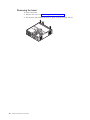
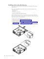
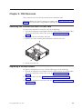
1
IBM
Hardware Maintenance Manual
Types 6826, 8317, 8318, and 8319
IBM
Hardware Maintenance Manual
Types 6826, 8317, 8318, and 8319
Note: Before using this information and the product it supports, be sure to read the
general information under “Notices” on page 143.
Second Edition (December 2002)
INTERNATIONAL BUSINESS MACHINES CORPORATION PROVIDES THIS PUBLICATION ″AS IS″ WITHOUT
ANY WARRANTY OF ANY KIND, EITHER EXPRESS OR IMPLIED, INCLUDING, BUT NOT LIMITED TO, THE
LIMITED WARRANTIES OF MERCHANTABILITY OR FITNESS FOR A PARTICULAR PURPOSE. Some
jurisdictions do not allow disclaimers or express or implied warranties in certain transactions; therefore, this
statement may not apply to you.
This publication could include technical inaccuracies or typographical errors. Changes are periodically made to the
information herein; these changes will be incorporated in new editions of the publication. IBM may make
improvements or changes in the products or the programs described in this publication at any time.
Requests for technical information about IBM products should be made to your IBM Authorized Dealer or your
IBM Marketing Representative.
© Copyright International Business Machines Corporation 2001. All rights reserved.
US Government Users Restricted Rights – Use, duplication or disclosure restricted by GSA ADP Schedule Contract
with IBM Corp.
Contents
Chapter 1. About this manual . . . . . 1
Important Safety Information .
.
.
.
.
.
.
.
Power supply
.
.
.
.
.
.
.
.
.
.
.
.
. 34
. 1
Chapter 7. Symptom-to-FRU Index . . . 37
Chapter 2. General Checkout. . . . . . 3
Chapter 3. General information . . . . . 5
Features . . . .
Specifications . .
Available options .
.
.
.
.
.
.
.
.
.
.
.
.
.
.
.
.
.
.
.
.
.
.
.
.
.
.
.
.
.
.
.
.
.
. 5
. 7
. 8
Chapter 4. Diagnostics . . . . . . . . 9
IBM Setup Utility program . . . . . . .
Product Recovery Program menu . . . . .
Diagnostics . . . . . . . . . . . .
Diagnostics program download. . . . .
Navigating through the diagnostics programs
Running diagnostics tests. . . . . . .
Test selection . . . . . . . . . . .
Test results . . . . . . . . . . .
Fixed disk advanced test (FDAT) . . . .
Quick and Full erase - hard drive . . . .
Viewing the test log . . . . . . . .
.
.
.
.
.
.
.
.
.
.
.
.
.
.
.
.
.
.
.
.
.
. 9
11
12
12
12
12
12
13
13
15
16
Chapter 5. Installing Options . . . . . 17
Installing external options . . . . . . . .
Locating controls and connectors on the front of
the computer . . . . . . . . . . . .
Locating connectors on the rear of the computer
Obtaining device drivers . . . . . . . .
Removing the cover . . . . . . . . .
Removing the bezel . . . . . . . . .
Locating components . . . . . . . . .
Accessing system board components and drives
Identifying parts on the system board . . .
Installing memory . . . . . . . . . .
Installing PCI adapters . . . . . . . .
Installing a drive in the disk drive tray . . .
Installing a cable lock . . . . . . . . .
Changing the battery . . . . . . . . .
Erasing a lost or forgotten password (clearing
CMOS) . . . . . . . . . . . . . .
Replacing the cover and connecting the cables.
. 17
. 17
18
. 18
. 19
. 20
. 21
22
. 23
. 24
. 25
. 26
. 28
. 29
. 30
. 30
Chapter 6. FRU Removals . . . . . . 33
Removing the retention bar and PCI riser card
Replacing a microprocessor . . . . . . .
System board . . . . . . . . . . . .
© Copyright IBM Corp. 2001
.
.
.
. 33
. 33
. 34
Hard disk drive boot error .
Power Supply Errors . . .
Diagnostic error codes . . .
Beep symptoms . . . . .
No-beep symptoms . . . .
POST error codes . . . .
Miscellaneous error messages
Undetermined problems . .
.
.
.
.
.
.
.
.
.
.
.
.
.
.
.
.
.
.
.
.
.
.
.
.
.
.
.
.
.
.
.
.
.
.
.
.
.
.
.
.
.
.
.
.
.
.
.
.
.
.
.
.
.
.
.
.
.
.
.
.
.
.
.
.
37
37
39
57
59
60
75
77
Chapter 8. Parts listing . . . . . . . . 79
Chapter 9. Additional Service
Information . . . . . . . . . . . . 103
Security features . . . . . . . . . . .
Passwords . . . . . . . . . . . .
Vital product data . . . . . . . . . .
Desktop Management Interface (DMI) . . .
Alert on LAN . . . . . . . . . . .
BIOS levels . . . . . . . . . . . . .
Flash (BIOS/VPD) update procedure . . . .
Flash recovery boot block jumper. . . . . .
Power management . . . . . . . . . .
Automatic configuration and power interface
(ACPI) BIOS. . . . . . . . . . . .
Advanced Power Management . . . . .
Automatic Hardware Power Management
features . . . . . . . . . . . . .
Automatic Power-On features . . . . . .
.
.
.
.
.
.
.
.
.
103
103
104
104
104
104
105
105
107
. 107
. 107
. 107
. 107
Chapter 10. Related service
information . . . . . . . . . . . . 109
Safety information. . . . . . . . .
General safety . . . . . . . . .
Electrical safety . . . . . . . . .
Safety inspection guide . . . . . .
Handling electrostatic discharge-sensitive
devices . . . . . . . . . . .
Grounding requirements. . . . . .
Safety notices (multi-lingual translations)
Send us your comments! . . . . . .
Problem determination tips. . . . . .
Notices . . . . . . . . . . . .
Trademarks . . . . . . . . . . .
. . . 109
. . . 109
. . . 110
. . . 111
.
.
.
.
.
.
.
.
.
.
.
.
.
.
.
.
.
.
.
.
.
112
113
113
142
143
143
144
iii
iv
Hardware Maintenance Manual
Chapter 1. About this manual
®
This manual contains service and reference information for IBM computer Types
6826, 8317, 8318, and 8319.
This manual is divided into product service sections and a related service section,
as follows:
v The product service sections include procedures for isolating problems to a FRU,
a Symptom-to-FRU Index, additional service information and an illustrated parts
catalog.
v The related service section includes safety notices and safety information, and
problem determination tips.
Note:
This manual is intended for trained servicers who are familiar with IBM Personal
Computer products. Use this manual along with advanced diagnostic tests to troubleshoot
problems effectively.
Before servicing an IBM product, be sure to review the “Safety information” on page 109.
Important Safety Information
Be sure to read all caution and danger statements in this book before performing
any of the instructions.
Prenez connaissance de toutes les consignes de type Attention et Danger avant de
procéder aux opérations décrites par les instructions.
Lesen Sie alle Sicherheitshinweise, bevor Sie eine Anweisung ausführen.
Accertarsi di leggere tutti gli avvisi di attenzione e di pericolo prima di effettuare
qualsiasi operazione.
© Copyright IBM Corp. 2001
1
Leia todas as instruções de cuidado e perigo antes de executar qualquer operação.
Lea atentamente todas las declaraciones de precaución y peligro ante de llevar a
cabo cualquier operación.
2
Hardware Maintenance Manual
Chapter 2. General Checkout
This general checkout procedure is for Type 6826, 8317, 8318, and 8319 computers.
Attention:
The drives in the computer you are servicing might have been rearranged or the drive
startup sequence changed. Be extremely careful during write operations such as copying,
saving or formatting. Data or programs can be overwritten if you select an incorrect drive.
Diagnostic error messages appear when a test program finds a problem with a
hardware option. For the test programs to properly determine if a test Passed, Failed
or Aborted, the test programs check the error-return code at test completion. See
“Diagnostics” on page 12.
General error messages appear if a problem or conflict is found by an application
program, the operating system, or both. For an explanation of these messages, refer
to the information supplied with that software package.
Notes:
v Type 6826, 8317, 8318, and 8319 computers default to come up quiet (no beep and no
memory count and checkpoint code display) when no errors are detected by POST.
v To enable beep and memory count and checkpoint code display when a successful POST
occurs, do the following:
1. Select Start Options in the Configuration/Setup Utility program (see “IBM Setup
Utility program” on page 9).
2.
Set Power-On Self-Test to Enhanced.
v Before replacing any FRUs, ensure that the latest level of BIOS is installed on the system.
A down-level BIOS might cause false errors and unnecessary replacement of the system
board. For more information on how to determine and obtain the latest level BIOS, see
“BIOS levels” on page 104.
v If multiple error codes are displayed, diagnose the first error code displayed.
v If the computer hangs with a POST error, go to ″Symptom-to-FRU Index″ on page 37.
v If the computer hangs and no error is displayed, go to “Undetermined problems” on
page 77.
v If an installed device is not recognized by the diagnostics program, that device might be
defective.
001
1. Power-off the computer and all external devices.
2. Check all cables and power cords.
3. Make sure the system board is seated properly.
4. Set all display controls to the middle position.
5. Power-on all external devices.
6. Power-on the computer.
7. Check for the following response:
v Readable instructions or the Main Menu.
DID YOU RECEIVE THE CORRECT RESPONSE?
© Copyright IBM Corp. 2001
3
If NO, continue to 002.
If YES, proceed to 003.
002
If the Power Management feature is enabled, do the following:
1. Start the Configuration/Setup Utility program (see “IBM Setup Utility
program” on page 9)
2. Select Power Management from the Configuration/Setup Utility program
menu.
3. Select APM.
4. Be sure APM BIOS Mode is set to Disabled. If it is not, press Left Arrow (}) or
Right Arrow (Æ) to change the setting.
5. Select Automatic Hardware Power Management.
6. Set Automatic Hardware Power Management to Disabled.
7. If the problem persists, continue to 003.
003
Run the Diagnostic programs. If necessary, refer to “Diagnostics” on page 12.
v If you receive an error, replace the part that the diagnostic program calls out or
go to ″Symptom-to-FRU Index″ on page 37.
v If the test stops and you cannot continue, replace the last device tested.
4
Hardware Maintenance Manual
Chapter 3. General information
This IBM® computer incorporates many of the latest advances in computer
technology and can be upgraded as needs change.
Adding hardware options to a computer is an easy way to increase its capabilities.
Instructions for installing external and internal options are included in this
publication. When adding an option, use these instructions along with the
instructions that come with the option.
Features
This section provides an overview of the computer features and preinstalled
software.
Microprocessor
v Intel® Celeron™ with 128 KB of internal L2 cache memory (some models)
v Intel Pentium® 4 with 512 KB of internal L2 cache memory and Intel NetBurst™
micro-architecture (some models)
Memory
Support for two dual inline memory modules (DIMMs)
Internal drives
v 3.5-inch, 1.44 MB diskette drive (some models)
v Hard disk drive
v EIDE CD-ROM, DVD, or CD-RW optical drive (some models)
Video subsystem
An integrated graphics controller for a Video Graphics Array (VGA) monitor
Audio subsystem
Integrated Soundmax with SPX
v Microphone and headphone connectors on the front panel
v Line in, line out, and microphone connectors on the rear panel
Connectivity
v 10/100 Mbps integrated Intel Ethernet controller that supports the Wake on
LAN® feature (some models)
v 10/1000 Mbps integrated Intel Ethernet controller that supports the Wake on
LAN® feature (some models)
v PCI modem (some models)
System management features
v Remote Program Load (RPL) and Dynamic Host Configuration Protocol (DHCP)
v Wake on LAN
v Wake on Ring (in the IBM Setup Utility program, this feature is called Serial Port
Ring Detect for an external modem and Modem Ring Detect for an internal PCI
modem)
© Copyright IBM Corp. 2001
5
v
v
v
v
Remote Administration
Automatic power-on startup
System Management (SM) BIOS and SM software
Ability to store POST hardware test results
Input/output features
v 25-pin, Extended Capabilities Port (ECP)/Extended Parallel Port (EPP)
v Two 9-pin serial connectors
v Six 4-pin, USB connectors (four on front panel and two on rear panel)
v PS/2® mouse connector
v PS/2 keyboard connector
v Ethernet connector
v VGA Monitor connector
v Three audio connectors (line in, line out, and microphone) on rear panel
v Two audio connectors (microphone and headphone) on front panel
Expansion
v Two 32-bit peripheral component interconnect (PCI) adapter slots
v Two DIMM sockets
Power
v 200 W power supply with manual voltage selection switch
v Automatic 50/60 Hz input frequency switching
v Advanced Power Management support
v Advanced Configuration and Power Interface (ACPI) support
Security features
v User and administrator passwords
v Support for the addition of a cable (Kennsington) lock
v Padlock loop for securing the cover
v Startup sequence control
v Startup without diskette drive, keyboard, or mouse
v Unattended start mode
v Diskette and hard disk I/O control
v Serial and parallel port I/O control
v Security profile by device
IBM preinstalled software
Your computer comes with preinstalled software. An operating system, device
drivers to support built-in features, and other support programs are included.
Operating systems (preinstalled) (varies by model)
Note: Not all countries or regions will have these operating systems.
v Microsoft® Windows® XP Home
v Microsoft Windows XP Professional
v Microsoft Windows 2000
6
Hardware Maintenance Manual
Specifications
This section lists the specifications for the computer.
Dimensions
Width: 12.2 inches (309 mm)
Heat output (approximate) in British thermal units (Btu)
per hour:
Height: 3.3 inches (84 mm)
Minimum configuration: 257 Btu/hr (75 watts)
Depth: 13.6 inches (345 mm)
Maximum configuration: 463 Btu/hr (135 watts)
Airflow
Weight
Minimum configuration as shipped: 7.4 kg (16.2 lbs)
Environment
Air temperature:
Operating: 10° to 35°C (50° to 95°F)
Non-operating: 10° to 60°C (50° to 140°F)
Humidity:
Operating: 8% to 80%
Non-operating: 8% to 90%
Transit: 8% to 90%
Electrical input
Input voltage:
Low range:
Minimum: 90 V ac
Approximately 0.23 cubic meters per minute
Acoustical noise-emission values
Note: In this computer, fan speed is controlled by
temperature, configuration, and software. Actual
noise-emission values might be different from the stated
values depending on the speed of the fan.
Average sound-pressure levels:
At operator position - 0.5 meters:
Idle: 33 dBA
Operating: 38 dBA
At bystander position - 1 meter:
Idle: 31 dBA
Operating: 37 dBA
Declared (upper limit) sound-power levels:
Maximum: 137 V ac
Idle: 4.6 bels
Input frequency range: 57–63 Hz
Operating: 5.0 bels
Voltage switch setting: 115 V ac
High range:
Minimum: 180 V ac
Maximum: 265 V ac
Input frequency range: 47–53 Hz
Voltage switch setting: 230 V ac
Input kilovolt-amperes (kVA) (approximate) 0.25 kVA
Note: These levels were measured in controlled
acoustical environments according to the procedures
specified by the American National Standards
Institute (ANSI) S12.10 and ISO 7779 and are reported
in accordance with ISO 9296. Actual sound-pressure
levels in a given location might exceed the average
values stated because of room reflections and other
nearby noise sources. The declared sound-power
levels indicate an upper limit, below which a large
number of computers will operate.
Chapter 3. General information
7
Available options
The following are some available options:
v External options
– Parallel port devices, such as printers and external drives
– Serial port devices, such as external modems and digital cameras
– Audio devices, such as external speakers for the sound system
– USB devices, such as printers, joysticks, and scanners
– Security device, such as a cable lock
– Monitors
v Internal options
– System memory, called dual inline memory modules (DIMMs)
– Peripheral component interconnect (PCI) adapters
– CD-ROM, DVD, or CD-RW drive, hard disk drive, diskette drive, and other
removable media drives
For the latest information about available options, see the following World Wide
Web pages:
v http://www.pc.ibm.com/us/accessories/
v http://www.pc.ibm.com/ww/accessories/
Information may also be obtained by calling the following telephone numbers:
v Within the United States, call 1-800-IBM-2YOU (1-800-426-2968), your IBM
reseller, or IBM marketing representative.
v Within Canada, call 1-800-565-3344 or 1-800-IBM-4YOU.
v Outside the United States and Canada, contact your IBM reseller or IBM
marketing representative.
8
Hardware Maintenance Manual
Chapter 4. Diagnostics
The following tools are available to help identify and resolve hardware-related
problems.
v Setup Utility program
v Power-On Self-Test (POST)
– POST Beep Codes
– Error Code Format
v Diagnostics program
v Recovery utility
– Factory Contents
– Partial recovery
v Repair utility
IBM Setup Utility program
The IBM Setup Utility program is stored in the electrically erasable programmable
read-only memory (EEPROM) of your computer. The IBM Setup Utility program is
used to view and change the configuration settings of your computer, regardless of
which operating system you are using. However, the operating-system settings
might override any similar settings in the IBM Setup Utility program.
To start the IBM Setup Utility program, do the following:
1. If the computer is already on when you start this procedure, shut down the
operating system and turn off the computer.
2. Turn on the computer and look for the following prompt on the logo screen:
(To interrupt normal startup, press Enter)
Press Enter when you see the prompt. The Startup Interrupt Menu is displayed.
3. Press F1 to start the IBM Setup Utility.
Note: If a user password is set, you must type the password to continue. If an
administrator password has been set, you cannot make any changes to
configuration using the IBM Setup Utility program until you type your
administrator password. See “Passwords” on page 103 for more
information.
The IBM Setup Utility might start automatically when POST detects that hardware
has been removed or new hardware has been installed in your computer. A sample
© Copyright IBM Corp. 2001
9
of the first IBM Setup Utility screen is shown here.
831941x
28KT10AUS
2810A
IBM
1234567
02/22/02
[13:34:25]
[02/22/2002]
The IBM Setup Utility program menu lists items that identify system configuration
topics.
When working with the IBM Setup Utility program menu, you must use the
keyboard. The keys used to perform various tasks are displayed at the bottom of
each screen.
When you finish viewing or changing settings, press Esc to return to the IBM
Setup Utility program menu (you might have to press Esc several times). If you
want to save the new settings, select Save Settings before you exit. Otherwise,
your changes will not be saved.
10
Hardware Maintenance Manual
Product Recovery Program menu
Type 6826, 8317, 8318, and 8319 machines have recovery and diagnostics programs
on a separate hard drive partition. The Enhanced Diagnostics diskette is not
shipped with the machine. To download the Diagnostics program, see “Diagnostics
program download” on page 12.
At startup, the machine displays the following prompt:
To start the Product Recovery Program, press F11
Attention: Make sure all data is backed up to avoid loss when the Product
Recovery program is used.
After depressing F11, you are given the following options.
v Factory Contents
This utility reformats the hard drive and restores all original files.
v System utilities
1. Repair (Windows NT 4.0 and 2000 Only)
This runs the Windows NT 4.0 emergency repair utility.
2. Run Diagnostics
3.
4.
5.
6.
Runs the IBM Enhanced Diagnostic Program.
Create a Diagnostics Diskette
Creates a bootable diagnostic diskette.
System Information
Displays information about your computer configuration and allows the user
to gather system information that would be needed during a Help Center
call.
Create Recovery/Repair Diskette (Disk to Disk Solution Only)
Creates a startable diskette to restore access to the IBM Product Recovery
program on the hard disk.
Recovery CD
In the event of a Hard Disk Drive failure, a Recovery CD can be used to
restore the Hard Disk Drive to the original factory preset. Be sure to use the
Recovery CD FRU list to obtain the proper recovery CD for the computer
model you are servicing.
Chapter 4. Diagnostics
11
Diagnostics
The Diagnostics program uses a full range of diagnostic utilities to determine the
operating condition of the computer’s hardware components.
For a complete list of error codes and messages, see ″Symptom-to-FRU Index″ on
page 37.
Diagnostics program download
To download the Diagnostics program, do the following:
v Go to http://www.pc.ibm.com/support/us/.
v Search for the machine Type and model in the ″Quick path to a product″ box on
the left.
v Select Downloadable Files from the optoins on the left.
v Select Diagnostic from the ″Downloadable files by category″ pull down menu.
Navigating through the diagnostics programs
Use the cursor movement keys to navigate within the menus.
v The Enter key is used to select a menu item.
v The Esc key is used to back up to the previous menu.
v For online help select F1.
Running diagnostics tests
There are four ways to run the diagnostic tests.
1. Using the cursor movement keys, highlight Run Normal Test or Run Quick
Test from the Diagnostics menu and then press Enter.
This will automatically run a pre-defined group of tests from each test category.
Run Normal Test runs a more extensive set of tests than does Run Quick Test
and takes longer to execute.
2. Press F5 to automatically run all selected tests in all categories. See ″Test
Selection″.
3. From within a test category, press Ctrl-Enter to automatically run only the
selected tests in that category. See ″Test Selection″.
4. Using the cursor movement keys, highlight a single test within a test category,
then press Enter. This will run only that test.
Press Esc at any time to stop the testing process.
Test results, (N/A, PASSED, FAILED, ABORTED), are displayed in the field beside
the test description and in the test log. See “Viewing the test log” on page 16.
Test selection
To select one or more tests, use the following procedure.
1. Open the corresponding test category.
2. Using the cursor movement keys, highlight the desired test.
3. Press the space bar.
A selected test is marked by >>. Pressing the space bar again de-selects a test
and removes the chevron.
4. Repeat steps 2 and 3 above to select all desired tests.
12
Hardware Maintenance Manual
Test results
Diagnostics test results will produce the following error code format:
Function
Code
Failure Type
DeviceID
Date
ChkDigits
Text
v Function Code:
Represents the feature or function within the PC.
v Failure Type:
Represents the type of error encountered.
v DeviceID:
Contains the component’s unit-ID which corresponds to either a fixed disk
drive, removable media drive, serial or parallel port, processor, specific RIMM,
or a device on the PCI bus.
v Date:
Contains the date on which the diagnostic test was run. The date is retrieved
from CMOS and displayed using the YYYYMMDD format.
v ChkDigits:
Contains a 2-digit check-digit value to ensure the following:
– Diagnostics were run on the specified date.
– Diagnostics were run on the specified IBM computer.
– The diagnostic error code is recorded correctly.
v Text:
Description of the error.
Note: See “Diagnostic error codes” on page 39 for error code listings.
Fixed disk advanced test (FDAT)
PC-Doctor’s (PCDR) Fixed-Disk Advanced Test module (FDAT) is a full-featured
highly configurable fixed-disk test suite. The configurable capabilities of FDAT
allow users to enable or disable specific tests, enable or disable testing features,
control the test log detail, alter testing parameters, etc. FDAT will test for and
report most commonly found errors on a fixed-disk drive and is able to test up to
128 SCSI and 4 IDE drives (up to 132 total drives). Drive information is gathered
through FDAT’s enumeration of available devices and user specific configuration
parameters located in the FDAT.INI. FDAT uses information supplied by these
features to indicate specifically what devices are available for test, what tests are
available for the device, device properties, etc. Modify the FDAT.INI file in PC
Doctor for DOS to change testing parameters
FDAT consists of the following subtests and features.
Fixed-Disk Tests:
v Seek Tests: - checks the physical operation of the drive head.
– Linear Seek
– Random Seek
– Min-Max Seek
– Butterfly Seek
v Verify Tests: - checks the integrity of the data present on the media.
– Linear Verify
Chapter 4. Diagnostics
13
– Random Verify
v Surface Scan Tests: - checks the drive media for defects.
– Surface Scan (Linear)
– Surface Scan (Aggressive) - this is disabled for normal customer use.
– Surface Scan (Random)
v SMART: - checks the SMART functionality for drives that support SMART.
– Start SMART Self-Test
– Get SMART test results
Other Test Features:
v Write-Splice Repair - detects and corrects Error Correction Code errors during
Verify tests.
v Auto Spin Down - a gradual spin down of the drive platters to avoid damaging
the media.
v Manufacturer Log - an in-depth manufacturer supported log of errors on the
drive.
Multitasking:
To allow simultaneous testing of multiple hard drives whenever possible, the
FDAT module is written as a set of multitasking functions. Each drive under test
can run the same test or run a different test at the same time. Each subtest is
written to handle a single test pass and all test variables are kept track of in a
structure unique for each drive . However, when testing IDE drives, FDAT will not
perform simultaneous testing of IDE drives that are attached to the same IDE
cable. For example, if FDAT is testing four IDE drives on a PC, it will perform
simultaneous testing on drives 1 and 3 first (master drives), then perform tests on
2 and 4 (slave drives). FDAT will also perform simultaneous testing on a master
and slave that are on separate IDE cables, but will not perform simultaneous tests
on a master and slave on the same IDE cable. This generally increases the amount
of time needed to test multiple IDE drives. Another limitation of FDAT’S
multitasking capability is the use of Ultra DMA (UDMA). Only one drive at a time
can access the UDMA channel and the UDMA channel buffer must be kept high in
order to maintain a speed advantage over other data transfer modes. In order to
use the UDMA channel during testing, users must disable the multitasking feature.
Destructive vs non-destructive testing:
Most of the tests found in FDAT are non-destructive. This means that PCDR will
preserve any data that is present on the tested media prior to beginning any
destructive operations (i.e. write operations). However, users can run certain tests
in destructive mode (i.e. surface scan tests). Destructive tests will speed up testing
because FDAT does not preserve the data on the media prior to the test beginning.
Unlike non-destructive tests, any data present on the media prior to the test
beginning is lost. FDAT allows for enabling or disabling destructive tests, as well
as specifying a range of destructive and non-destructive sectors on the tested drive.
This is done through the configuration of the FDAT.INI .If destructive and
non-destructive ranges somehow overlap, then the overlapped area is considered
non-destructive. For example, if users specify both destructive and non-destructive
ranges as the same, then the entire drive is tested as non-destructive.
14
Hardware Maintenance Manual
Quick and Full erase - hard drive
The Diagnostics program offers two hard drive format utilities:
v Quick Erase Hard Drive
v Full Erase Hard Drive
The Quick Erase Hard Drive provides a DOS utility that performs the following
steps.
v Destroys the Master Boot Record (MBR) on the hard drive.
v Destroys all copies of the FAT Table on all partitions (both the master and
backup).
v Destroys the partition table.
v Provides messages that warn the user that this is a non-recoverable process.
Chapter 4. Diagnostics
15
The Full Erase Hard Drive provides a DOS utility that performs the following
steps.
v Performs all the steps in Quick Erase.
v Provides a DOS utility that writes random data to all sectors of the hard drive.
v Provide an estimate of time to completion along with a visual representation of
completion status.
v Provides messages that warn the user about non-recoverable process.
Important: Make sure that all data is backed up before using the Quick or Full Erase
functions.
To select the Quick Erase or Full Erase Hard Drive utility, use the following
procedure.
1. Select the UTILITY option on the toolbar and press Enter.
2. Select either the QUICK ERASE or FULL ERASE HARD DISK option and
follow the instructions.
Viewing the test log
Errors reported by the diagnostic test will be displayed by the program as a failed
test.
To view details of a failure or to view a list of test results, use the following
procedure from any test category screen.
v Press F3 to activate the log file.
v Press F3 again to save the file to diskette or F2 to print the file.
16
Hardware Maintenance Manual
Chapter 5. Installing Options
This section contains information on adding or replacing customer options.
Installing external options
This section shows the various external connectors on the computer to which
external options may be attached. When adding an external option, use the
information in this section to identify the required connector, and then use the
instructions that come with the option to make the connection and install any
software or device drivers that are required for the option.
Locating controls and connectors on the front of the
computer
The following illustration shows locations of the controls and connectors on the
front of the computer.
1
2
3
4
© Copyright IBM Corp. 2001
Diskette drive
Headphone connector
Microphone connector
USB connectors (4)
5
6
7
8
Hard disk drive activity indicator
Power-on indicator
Power button
CD or DVD drive
17
Locating connectors on the rear of the computer
The following illustration shows locations of connectors on the rear of the
computer.
1
2
3
4
5
6
7
Serial connector
PCI adapter slots
Ethernet connector
Parallel connector
Serial connector
Microphone connector
Audio line-in connector
8
9
10
11
12
13
Audio line-out connector
VGA monitor connector
USB connectors (2)
PS/2 keyboard connector
PS/2 mouse connector
Power cord connector
Note: Some connectors on the rear of your computer are color-coded to help
determine where to connect the cables.
Obtaining device drivers
Device drivers for operating systems that are not preinstalled may be obtained at
http://www.ibm.com/pc/support/ on the World Wide Web. Installation
instructions are provided in README files with the device-driver files.
18
Hardware Maintenance Manual
Removing the cover
To remove the cover:
1. Shut down the operating system, remove any media (diskettes, CDs, or tapes)
from the drives, and turn off all attached devices and the computer.
2. Unplug all power cords from electrical outlets.
3. Disconnect all cables attached to the computer. This includes power cords,
input/output (I/O) cables, and any other cables that are connected to the
computer.
4. Remove the floor stand, if attached.
5. Remove the padlock or cable lock if installed.
6. Remove the two thumbscrews that secure the cover at the rear of the system
unit.
7. Using the handle provided at the rear, pull the cover to the rear and lift it off.
Chapter 5. Installing Options
19
Removing the bezel
To remove the bezel:
1. Remove the cover. See “Removing the cover” on page 19.
2. Lift the three tabs holding the bezel in place and pull forward and off.
20
Hardware Maintenance Manual
Locating components
The following illustration will help you locate the various components in the
computer.
1
2
3
4
5
Diskette drive
System board
DIMM connectors
PCI riser
Power supply
6
7
8
9
Hard disk drive
CD or DVD drive
Battery
Disk drive tray
Chapter 5. Installing Options
21
Accessing system board components and drives
To access some components on the system board such as memory, the battery, and
the Clear CMOS/BIOS recovery jumper, it may be necessary to slide the diskette
and CD drive tray outward to the front of the computer.
To
1.
2.
3.
access system board components or drives:
Turn off the computer.
Remove the cover. See “Removing the cover” on page 19.
Remove the screw securing the drive tray to the riser card support.
4. Press in on the drive tray buttons at each side as shown, and slide tray forward
to access drives.
Notes:
a. It may be necessary to disconnect some cables attached to the drives to
allow the drive tray to slide out far enough to access some system board
components. To remove the drive tray completely, disconnect all the cables
attached to the diskette and CD drives.
b. Make sure you note the location of any cables that you disconnect from the
drives.
5. Slide the drive tray to the front just far enough to access the necessary system
board component.
6. If any PCI adapters are installed, remove the PCI riser and adapter cards. Do
not remove any adapters from the riser card.
22
Hardware Maintenance Manual
Identifying parts on the system board
The system board (sometimes called the planar or motherboard) is the main circuit
board in the computer. It provides basic computer functions and supports a variety
of devices that are IBM-installed or that can be installed later.
The following illustration shows the locations of parts on the system board.
1
2
3
4
5
6
7
Microprocessor
DIMM connectors
Front panel connector
CD audio connector
PCI riser connector
Secondary IDE connector
Primary IDE connector
8
9
10
11
12
13
14
Battery
Diskette drive connector
Clear CMOS/BIOS recovery jumper
System fan connector
Microprocessor fan connector
Main power
Microprocessor power connector
Chapter 5. Installing Options
23
Installing memory
Type 6826, 8317, 8318, and 8319 computers have two connectors for installing dual
inline memory modules (DIMMs) that provide up to a maximum of 2 GB of
system memory.
When installing memory, the following rules apply:
v Use 2.5 V, 184-pin, double data rate synchronous dynamic random access
memory (DDR SDRAM), non-ECC DIMMs.
v Use 128 MB, 256 MB, 512 MB, or 1 GB DIMMs in any combination.
Note: Only DDR SDRAM DIMMs can be used.
To install DIMMs:
1. Access the system board. See “Accessing system board components and drives”
on page 22.
2. Locate the DIMM connectors. See “Identifying parts on the system board” on
page 23.
3. Open the retaining clips.
4. Make sure the notch in the DIMM aligns with the tab on the connector. Push or
insert the memory module straight down into the connector until the retaining
clips close.
5. Slide the CD and diskette drive tray back into position and reconnect any
cables that were disconnected. Insert the holding screw.
Note: Be sure to align the drive tray properly on the drive tray tracks,
otherwise the drive tray will not sit properly, nor will the cover attach
properly.
6. Replace the PCI riser and adapters if it was removed.
24
Hardware Maintenance Manual
7. Replace the cover. See “Replacing the cover and connecting the cables” on
page 30.
Installing PCI adapters
This section provides information and instructions for installing and removing PCI
adapters. The computer has a riser card with two PCI expansion slots.
To install a PCI adapter:
1. Remove the cover. See “Removing the cover” on page 19.
2. Remove the PCI riser and adapters that are already installed.
3. Remove the adapter-slot-cover latch and the slot cover for the appropriate
expansion slot.
4. Remove the adapter from its static-protective package
5. Install the adapter into the appropriate slot on the PCI riser.
6. Replace the adapter-slot-cover latch.
7. Install the PCI riser and adapters.
8. Replace the cover. See “Replacing the cover and connecting the cables” on
page 30.
What to do next:
v To work with another option, go to the appropriate section.
v To complete the installation, go to “Replacing the cover and connecting the
cables” on page 30.
Chapter 5. Installing Options
25
Installing a drive in the disk drive tray
This section provides information and instructions for installing and removing
internal drives.
Drives that are available for Type 6826, 8317, 8318, and 8319 computers are:
v Hard disk drives
v Tape drives
v CD drives or DVD drives
v Diskette and other removable media drives
When installing an internal drive, it is important to note what type and size of
drive that you can install in each bay. Also, it is important to correctly connect the
internal drive cables to the installed drive.
To
1.
2.
3.
install a drive in the disk drive tray, follow these steps.
Remove the cover. See “Removing the cover” on page 19.
Remove the bezel. See “Removing the bezel” on page 20.
Remove the disk drive tray. See “Accessing system board components and
drives” on page 22 and “Locating components” on page 21.
4. Install the drive into the bay. Align the screw holes, and insert the four screws.
26
Hardware Maintenance Manual
5. Reinstall the disk drive tray. Go to “Connecting a diskette drive” on page 28 or
“Connecting an IDE CD drive”.
Note: Be sure to connect the system fan cable before sliding the disk drive tray
back in.
6. Replace the bezel and cover.
Replacing the hard disk drive
To replace the hard disk drive, follow these steps.
1. Remove the cover. See “Removing the cover” on page 19.
2. Remove the disk drive tray. See “Accessing system board components and
drives” on page 22.
3. Disconnect the signal and power cables from the existing hard disk drive and
remove the drive. Do not disconnect the signal cable from the system board.
4. Insert the hard drive into the hard disk cage and secure with 4 screws.
5. Slide the hard disk cage into its slot and make sure the plastic retaining clip is
secure. Connect the signal and power cables to the drive.
6. Reinstall the disk drive tray and connect the signal and power cables for the
diskette and CD drives.
What to do next:
v To work with another option, go to the appropriate section.
v To complete the installation, go to “Replacing the cover and connecting the
cables” on page 30.
Connecting an IDE CD drive
1. Locate the signal cable that came with your computer or with the new drive.
2. Locate the secondary IDE connector on the system board. See “Identifying parts
on the system board” on page 23.
3. Connect one end of the signal cable to the drive and the other to the secondary
IDE connector on the system board.
4. If you have a CD-ROM drive audio cable, connect it to the drive and the
system board. For the location of the CD audio connector, see “Identifying
parts on the system board” on page 23.
Chapter 5. Installing Options
27
What to do next:
v To work with another option, go to the appropriate section.
v To complete the installation, go to “Replacing the cover and connecting the
cables” on page 30.
Connecting a diskette drive
1. Locate the cable that came with your computer or with the new drive.
2. Locate the diskette drive connector on the system board. See “Identifying parts
on the system board” on page 23.
3. Connect one end of the signal cable to the drive and the other to the diskette
drive connector on the system board.
Note: Make sure the twisted end of the cable is plugged into the drive.
What to do next:
v To work with another option, go to the appropriate section.
v To complete the installation, go to “Replacing the cover and connecting the
cables” on page 30.
Installing a cable lock
To help to protect against theft, an optional cable lock can be installed to secure the
computer to a desk, table, or other fixture. This type of cable lock also
automatically locks the computer cover to the chassis. The cable-lock latch on the
computer accommodates the same type of cable lock used with many laptop
computers. Cable Locks can be ordered directly from IBM. For more information,
see Finding options from IBM in Access IBM.
28
Hardware Maintenance Manual
See the following illustration for cable lock installation.
®
Changing the battery
Type 6826, 8317, 8318, 8319 computers have a special type of memory that
maintains the date, time, and settings for built-in features, such as parallel-port
assignments (configuration). A battery keeps this information active when the
computer is turned off.
The battery normally requires no charging or maintenance throughout its life;
however, no battery lasts forever. If the battery fails, the date, time, and
configuration information (including passwords) are lost. An error message is
displayed when you turn on the computer.
Refer to “Safety information” on page 109 for information about replacing and
disposing of the battery.
To change the battery:
1. Refer to “Identifying parts on the system board” on page 23 and locate the
battery.
2. Remove the PCI riser and any cables that impede access to the battery.
3. Remove the old battery.
Chapter 5. Installing Options
29
4. Install the new battery.
5. Reconnect any cables that were disconnected. Slide the drive tray back into the
computer, making sure both side tabs lock.
6. Install the PCI riser and adapters if removed.
7. Replace the cover, and connect the cables. See “Replacing the cover and
connecting the cables”.
Note: When the computer is turned on for the first time after battery
replacement, an error message might be displayed. This is normal after
replacing the battery.
8. Turn on the computer and all attached devices.
9. Use the IBM Setup Utility program to set the date and time and any
passwords.
Erasing a lost or forgotten password (clearing CMOS)
This section applies to lost or forgotten passwords. For more information about
lost or forgotten passwords, go to Access IBM.
To erase a forgotten password:
1. Refer to “Accessing system board components and drives” on page 22.
2. Locate the Clear CMOS/BIOS recovery jumper on the system board. See
“Identifying parts on the system board” on page 23.
3. Move the jumper from the standard position (pins 1 and 2, closest to the
battery) to the maintenance or configure position (pins 2 and 3, farthest from
the battery).
4. Slide both drive trays back into the computer and secure with the holding
screws. Reconnect any cables that were disconnected.
5. Install the PCI riser and adapters.
6. Replace the cover, and connect the power cable. See “Replacing the cover and
connecting the cables”.
7. Restart the computer, leave it on for approximately 10 seconds, and then turn
off the computer.
8. Repeat step 1.
9. Move the jumper back to the standard (pins 1 and 2).
10. Reassemble the computer and replace the cover. See “Replacing the cover and
connecting the cables”.
Replacing the cover and connecting the cables
After working with options, reinstall any removed parts, replace the cover, and
reconnect cables, including telephone lines and power cords. Also, depending on
the option that is installed, you might need to confirm the updated information in
the IBM Setup Utility program.
To replace the cover and connect cables to your computer:
30
Hardware Maintenance Manual
1. Ensure that all components have been reassembled correctly and that no tools
or loose screws are left inside your computer.
2. Clear any cables that might impede the replacement of the cover.
3. Place the cover over the computer and slide it to the rear until it is fully closed.
Secure the cover with the two thumbscrews.
4. If your computer is being placed in the vertical position, attach the floor stand.
Attention: To prevent overheating and possible component damage, always
attach the floor stand when placing the computer in the vertical position.
5. Reconnect the external cables and power cords to the computer. See “Locating
connectors on the rear of the computer” on page 18.
6. To update the configuration, see “IBM Setup Utility program” on page 9.
Chapter 5. Installing Options
31
32
Hardware Maintenance Manual
Chapter 6. FRU Removals
These removals are to be done by trained service technicians only.
Important: Before you install or remove any option, read “Safety information” on
page 109. These precautions and guidelines will help you work safely.
Removing the retention bar and PCI riser card
To remove the retention bar and riser card, do the following:
1. Turn off the computer and peripheral devices and disconnect all external cables
and power cords; then, remove the cover. See “Removing the cover” on
page 19.
2. Disconnect all riser card cables and wires.
3. Remove the screws securing the retention bar and PCI riser card.
4. Lift the riser card out.
Replacing a microprocessor
To replace a microprocessor in any of the machine types, do the following:
1. Turn off the computer and peripheral devices and disconnect all external cables
and power cords; then, remove the cover. See “Removing the cover” on
page 19.
2. Remove the drive tray. See “Installing a drive in the disk drive tray” on
page 26.
3. Remove the retention bar and riser card. See “Removing the retention bar and
PCI riser card”.
© Copyright IBM Corp. 2001
33
4. Unscrew the fansink from the system board and carefully lift it off. The
processor will come with it, attached to the bottom by thermal grease.
5. To remove the fansink from the processor, remove the assembly from the
system board, and twist the processor to break the seal formed by the thermal
grease and remove.
System board
To remove the system board, do the following:
1. Turn off the computer and peripheral devices and disconnect all external cables
and power cords; then, remove the cover. See “Removing the cover” on
page 19.
2. Remove the retention bar and riser card. See “Removing the retention bar and
PCI riser card” on page 33.
3. Remove the drive tray. See “Installing a drive in the disk drive tray” on
page 26.
4. Disconnect all wires connected to the system board.
5. Remove the fansink and processor. See “Replacing a microprocessor” on
page 33.
6. Remove the 4 screws that attach the system board to the chassis.
7. Lift out the system board.
Power supply
To remove the power supply, do the following:
1. Turn off the computer and peripheral devices and disconnect all external cables
and power cords; then, remove the cover. See “Removing the cover” on
page 19.
34
Hardware Maintenance Manual
2. Remove the drive tray. See “Installing a drive in the disk drive tray” on
page 26.
3. Remove the hard disk drive. See “Replacing the hard disk drive” on page 27.
4. Disconnect all power supply wires.
5. Remove the system board. See“System board” on page 34.
6. Remove the screws holding the power supply.
7. Lift out the power supply.
Chapter 6. FRU Removals
35
36
Hardware Maintenance Manual
Chapter 7. Symptom-to-FRU Index
The Symptom-to-FRU index lists error symptoms and possible causes. The most
likely cause is listed first. Always begin with ″General Checkout″ on page 3. This
index can also be used to help you decide which FRUs to have available when
servicing a computer. If you are unable to correct the problem using this index, go
to “Undetermined problems” on page 77.
Notes:
v If you have both an error message and an incorrect audio response, diagnose the error
message first.
v If you cannot run the diagnostic tests or you get a diagnostic error code when running a
test, but did receive a POST error message, diagnose the POST error message first.
v If you did not receive any error message, look for a description of your error symptoms
in the first part of this index.
v Check the hard disk drive jumper settings before you replace a hard disk drive.
Hard disk drive boot error
A hard disk drive boot error (error codes 1962 and I999030X) can have the
following causes.
Error
FRU/Action
The start-up drive is not in the boot
sequence in configuration.
Check the configuration and ensure the
start-up drive is in the boot sequence.
No operating system installed on the boot
drive.
Install an operating system on the boot
drive.
The boot sector on the start-up drive is
corrupted.
The drive must be formatted, do the
following:
1. Attempt to access and recover (back-up)
the failing hard disk drive.
2. Using the operating systems programs,
format the hard disk drive.
The drive is defective.
Replace the hard disk drive.
Power Supply Errors
If the power-on indicator is not on, the power supply fan is not running, or the
computer will not power-off, use the following procedures.
Check/Verify
FRU/Action
Check the following for proper installation.
Reseat
v Power Cord
v On/Off Switch connector
v On/Off Switch Power Supply connector
v System Board Power Supply connectors
v Microprocessor(s) connection
Check the power-on switch for continuity.
© Copyright IBM Corp. 2001
Power Cord
37
38
Check/Verify
FRU/Action
Check the power-on switch for continuity.
Power-on Switch
Hardware Maintenance Manual
Diagnostic error codes
Refer to the following diagnostic error codes when using the diagnostic tests. See
″Diagnostics″ on page 9 for the specific type for information about the Diagnostic
programs.
In the following index, X can represent any number.
Diagnostic Error Code
FRU/Action
000-000-XXX
BIOS Test Passed
1. No action
000-002-XXX
BIOS Timeout
1. Flash the system
000-024-XXX
BIOS Addressing test failure
1. Flash the system
000-025-XXX
BIOS Checksum Value error
1. Flash the system
2. System board
2. System board
2. Boot block
3. System board
000-026-XXX
FLASH data error
1. Flash the system
2. Boot block
3. System board
000-027-XXX
BIOS Configuration/Setup error
1. Run Setup
2. Flash the system
3. Boot block
4. System board
000-034-XXX
BIOS Buffer Allocation failure
1. Reboot the system
2. Flash the system
3. Run memory test
4. System board
000-035-XXX
BIOS Reset Condition detected
1. Flash the system
000-036-XXX
BIOS Register error
1. Flash the system
2. System board
2. Boot block
3. System board
000-038-XXX
BIOS Extension failure
1. Flash the system
2. Adapter card
3. System board
000-039-XXX
BIOS DMI data error
1. Flash the system
000-195-XXX
BIOS Test aborted by user
1. Information
000-196-XXX
BIOS test halt, error threshold exceeded
1. Press F3 to review the log file
2. System board
2. Re-start the test, if necessary
2. Re-start the test to reset the log file
Chapter 7. Symptom-to-FRU Index
39
Diagnostic Error Code
FRU/Action
000-197-XXX
BIOS test warning
1. Make sure the component that is called
out is connected and/or enabled
2. Re-run test
3. Component that is called out in warning
statement
4. Component under test
000-198-XXX
BIOS test aborted
1. If a component is called out, make sure
it is connected and/or enabled
2. Flash the system and re-test
3. Go to the ″Undetermined problems″
section
000-199-XXX
BIOS test failed, cause unknown
1. Go to the ″Undetermined problems″
section
2. Flash the system and re-test
3. Replace component under function test
000-250-XXX
BIOS APM failure
1. Flash the system
000-270-XXX
BIOS ACPI failure
1. Flash the system
001-000-XXX
System Test Passed
1. No action
001-00X-XXX
System Error
1. System board
001-01X-XXX
System Error
1. System board
001-024-XXX
System Addressing test failure
1. System board
001-025-XXX
System Checksum Value error
1. Flash the system
001-026-XXX
System FLASH data error
1. Flash the system
001-027-XXX
System Configuration/Setup error
1. Run Setup
2. System board
2. System board
2. System board
2. System board
2. Flash the system
3. System board
001-032-XXX
System Device Controller failure
1. System board
001-034-XXX
System Device Buffer Allocation failure
1. Reboot the system
2. Flash the system
3. Run memory test
4. System board
40
001-035-XXX
System Device Reset condition detected
1. System board
001-036-XXX
System Register error
1. System board
Hardware Maintenance Manual
Diagnostic Error Code
FRU/Action
001-038-XXX
System Extension failure
1. Adapter card
001-039-XXX
System DMI data structure error
1. Flash the system
001-040-XXX
System IRQ failure
1. Power-off/on system and re-test
001-041-XXX
System DMA failure
1. Power-off/on system and re-test
001-195-XXX
System Test aborted by user
1. Information
001-196-XXX
System test halt, error threshold exceeded
1. Press F3 to review the log file
001-197-XXX
System test warning
1. Make sure the component that is called
out is connected and/or enabled
2. System board
2. System board
2. System board
2. System board
2. Re-start the test, if necessary
2. Re-start the test to reset the log file
2. Re-run test
3. Component that is called out in warning
statement
4. Component under test
001-198-XXX
System test aborted
1. If a component is called out, make sure
it is connected and/or enabled
2. Flash the system and re-test
3. Go to the ″Undetermined problems″
section
001-199-XXX
System test failed, cause unknown
1. Go to the ″Undetermined problems″
section
2. Flash the system and re-test
3. Replace component under function test
001-250-XXX
System ECC error
1. System board
001-254-XXX
001-255-XXX
001-256-XXX
001-257-XXX
System DMA error
1. System board
001-260-XXX
001-264-XXX
System IRQ error
1. System board
001-268-XXX
System IRQ1 failure
1. Device on IRQ1
001-269-XXX
System IRQ2 failure
1. Device on IRQ2
001-270-XXX
System IRQ3 failure
1. Device on IRQ3
2. System board
2. System board
2. System board
Chapter 7. Symptom-to-FRU Index
41
42
Diagnostic Error Code
FRU/Action
001-271-XXX
System IRQ4 failure
1. Device on IRQ4
001-272-XXX
System IRQ5 failure
1. Device on IRQ5
001-273-XXX
System IRQ6
(diskette drive) failure
1. Diskette Cable
001-274-XXX
System IRQ7 failure
1. Device on IRQ7
001-275-XXX
System IRQ8 failure
1. Device on IRQ8
001-276-XXX
System IRQ9 failure
1. Device on IRQ9
001-277-XXX
System IRQ10 failure
1. Device on IRQ10
001-278-XXX
System IRQ11 failure
1. Device on IRQ11
001-279-XXX
System IRQ12 failure
1. Device on IRQ12
001-280-XXX
System IRQ13 failure
1. Device on IRQ13
001-281-XXX
System IRQ14
(hard disk drive) failure
1. Hard disk drive cable
001-282-XXX
System IRQ15 failure
1. Device on IRQ15
001-286-XXX
001-287-XXX
001-288-XXX
System Timer failure
1. System board
001-292-XXX
System CMOS
RAM error
1. Run Setup and re-test
001-293-XXX
System CMOS Battery
1. Battery
001-298-XXX
System RTC date/time update failure
1. Flash the system
001-299-XXX
System RTC periodic interrupt failure
1. System board
001-300-XXX
System RTC Alarm failure
1. System board
Hardware Maintenance Manual
2. System board
2. System board
2. Diskette drive
3. System board
2. System board
2. System board
2. System board
2. System board
2. System board
2. System board
2. System board
2. Hard disk drive
3. System board
2. System board
2. System board
2. System board
2. System board
Diagnostic Error Code
FRU/Action
001-301-XXX
System RTC Century byte error
1. Flash the system
005-000-XXX
Video Test Passed
1. No action
005-00X-XXX
Video error
1. Video card, if installed
005-010-XXX
005-011-XXX
005-012-XXX
005-013-XXX
Video Signal failure
1. Video card, if installed
005-016-XXX
Video Simple Pattern
test failure
1. Video Ram
005-024-XXX
Video Addressing test failure
1. Video card, if installed
005-025-XXX
Video Checksum Value error
1. Video card, if installed
005-027-XXX
Video Configuration/Setup error
1. Run Setup
2. System board
2. System board
2. System board
2. Video card, if installed
3. System board
2. System board
2. System board
2. Video drivers update
3. Video card, if installed
4. System board
005-031-XXX
Video Device Cable failure
1. Video cable
2. Monitor
3. Video card, if installed
4. System board
005-032-XXX
Video Device Controller failure
1. Video card, if installed
005-036-XXX
Video Register error
1. Video card, if installed
005-038-XXX
System BIOS extension failure
1. Video card, if installed
005-040-XXX
Video IRQ failure
1. Video card, if installed
005-195-XXX
Video Test aborted by user
1. Information
005-196-XXX
Video test halt, error threshold exceeded
1. Press F3 to review the log file
2. System board
2. System board
2. System board
2. System board
2. Re-start the test, if necessary
2. Re-start the test to reset the log file
Chapter 7. Symptom-to-FRU Index
43
Diagnostic Error Code
FRU/Action
005-197-XXX
Video test warning
1. Make sure the component that is called
out is connected and/or enabled
2. Re-run test
3. Component that is called out in warning
statement
4. Component under test
005-198-XXX
Video test aborted
1. If a component is called out, make sure
it is connected and/or enabled
2. Flash the system and re-test
3. Go to the ″Undetermined problems″
section
005-199-XXX
Video test failed, cause unknown
1. Go to the ″Undetermined problems″
section
2. Flash the system and re-test
3. Replace component under function test
005-2XX-XXX
005-3XX-XXX
Video subsystem error
1. Video card, if installed
006-000-XXX
Diskette interface Test Passed
1. No action
006-0XX-XXX
Diskette interface error
1. Diskette drive Cable
2. System board
2. Diskette drive
3. System board
006-195-XXX
Diskette interface Test aborted by user
1. Information
006-196-XXX
Diskette interface test halt, error threshold
exceeded
1. Press F3 to review the log file
006-197-XXX
Diskette interface test warning
1. If a component is called out, make sure
it is connected and/or enabled
2. Re-start the test, if necessary
2. Re-start the test to reset the log file
2. Re-run test
3. Component that is called out in warning
statement
4. Component under test
006-198-XXX
Diskette interface test aborted
1. If a component is called out, make sure
it is connected and/or enabled
2. Flash the system and re-test
3. Go to the ″Undetermined problems″
section
006-199-XXX
1. Go to the ″Undetermined problems″
Diskette interface test failed, cause unknown
section
2. Flash the system and re-test
3. Replace component under function test
006-25X-XXX
Diskette interface Error
1. Diskette drive cable
2. Diskette drive
3. System board
44
Hardware Maintenance Manual
Diagnostic Error Code
FRU/Action
011-000-XXX
Serial port Interface Test Passed
1. No action
011-001-XXX
Serial port Presence
1. Remove external serial device, if
present
2. Run setup, enable port
3. System board
011-002-XXX
011-003-XXX
Serial port Timeout/Parity error
1. System board
011-013-XXX
011-014-XXX
Serial port Control Signal/Loopback test
failure
1. System board
011-015-XXX
Serial port External Loopback failure
1. Wrap plug
Note: Ensure the wrap plug is removed
after testing is completed. Otherwise, the
system may not shut down properly.
2. System board
011-027-XXX
Serial port Configuration/Setup error
1. Run Setup, enable port
2. Flash the system
3. System board
011-03X-XXX
011-04X-XXX
Serial port failure
1. System board
011-195-XXX
Serial port Test aborted by user
1. Information
2. Re-start the test, if necessary
011-196-XXX
1. Press F3 to review the log file
Serial port test halt, error threshold exceeded
2. Re-start the test to reset the log file
011-197-XXX
Serial port test warning
1. Make sure the component that is called
out is connected and/or enabled
2. Re-run test
3. Component that is called out in warning
statement
4. Component under test
011-198-XXX
Serial port test aborted
1. If a component is called out, make sure
it is connected and/or enabled
2. Flash the system and re-test
3. Go to the ″Undetermined problems″
section
011-199-XXX
Serial port test failed, cause unknown
1. Go to the ″Undetermined problems″
section
2. Flash the system and re-test
3. Replace component under function test
011-2XX-XXX
Serial port signal failure
1. External serial device
2. System board
Chapter 7. Symptom-to-FRU Index
45
Diagnostic Error Code
FRU/Action
014-000-XXX
Parallel port Interface Test Passed
1. No action
014-001-XXX
Parallel port Presence
1. Remove external parallel device, if
present
2. Run setup, enable port
3. System board
014-002-XXX
014-003-XXX
Parallel port Timeout/Parity error
1. System board
014-013-XXX
014-014-XXX
Parallel port Control Signal/Loopback test
failure
1. System board
014-015-XXX
Parallel port External Loopback failure
1. Wrap plug
014-027-XXX
Parallel port Configuration/Setup error
1. Run Setup, enable port
2. System board
2. Flash the system
3. System board
014-03X-XXX
014-04X-XXX
Parallel port failure
1. System board
014-195-XXX
Parallel port Test aborted by user
1. Information
014-196-XXX
Parallel port test halt, error threshold
exceeded
1. Press F3 to review the log file
014-197-XXX
Parallel port test warning
1. Make sure the component that is called
out is connected and/or enabled
2. Re-start the test, if necessary
2. Re-start the test to reset the log file
2. Re-run test
3. Component that is called out in warning
statement
4. Component under test
014-198-XXX
Parallel port test aborted
1. If a component is called out, make sure
it is connected and/or enabled
2. Flash the system and re-test
3. Go to the ″Undetermined problems″
section
014-199-XXX
Parallel port test failed, cause unknown
1. Go to the ″Undetermined problems″
section
2. Flash the system and re-test
3. Replace component under function test
46
014-2XX-XXX
014-3XX-XXX
Parallel port failure
1. External parallel device
015-000-XXX
USB port Interface Test Passed
1. No action
Hardware Maintenance Manual
2. System board
Diagnostic Error Code
FRU/Action
015-001-XXX
USB port Presence
1. Remove USB device(s) and re-test
015-002-XXX
USB port Timeout
1. Remove USB device(s) and re-test
015-015-XXX
USB port External Loopback failure
1. Remove USB device(s) and re-test
015-027-XXX
USB port Configuration/Setup error
1. Flash the system
015-032-XXX
USB port Device Controller failure
1. System board
015-034-XXX
USB port buffer
allocation failure
1. Reboot the system
2. System board
2. System board
2. System board
2. System board
2. Flash the system
3. Run memory test
4. System board
015-035-XXX
USB port Reset condition detected
1. Remove USB device(s) and re-test
015-036-XXX
USB port Register error
1. System board
015-040-XXX
USB port IRQ failure
1. Run setup and check for conflicts
2. System board
2. Flash the system
3. System board
015-195-XXX
USB port Test aborted by user
1. Information
015-196-XXX
USB port test halt, error threshold exceeded
1. Press F3 to review the log file
015-197-XXX
USB port test warning
1. Make sure the component that is called
out is connected and/or enabled
2. Re-start the test, if necessary
2. Re-start the test to reset the log file
2. Re-run test
3. Component that is called out in warning
statement
4. Component under test
015-198-XXX
USB port test aborted
1. If a component is called out, make sure
it is connected and/or enabled
2. Flash the system and re-test
3. Go to the ″Undetermined problems″
section
015-199-XXX
USB port test failed, cause unknown
1. Go to the ″Undetermined problems″
section
2. Flash the system and re-test
3. Replace component under function test
018-000-XXX
PCI Card Test Passed
1. No action
Chapter 7. Symptom-to-FRU Index
47
Diagnostic Error Code
FRU/Action
018-0XX-XXX
PCI Card Failure
1. Riser card, if installed
018-195-XXX
PCI Card Test aborted by user
1. PCI card
2. System board
2. Information
3. Re-start the test, if necessary
018-196-XXX
PCI Card test halt, error threshold exceeded
1. Press F3 to review the log file
018-197-XXX
PCI Card test warning
1. Make sure the component that is called
out is connected and/or enabled
2. Re-start the test to reset the log file
2. Re-run test
3. Component that is called out in warning
statement
4. Component under test
018-198-XXX
PCI Card test aborted
1. Make sure the component that is called
out is connected and/or enabled
2. Flash the system and re-test
3. Go to the ″Undetermined problems″
section
018-199-XXX
PCI Card test failed, cause unknown
1. Go to the ″Undetermined problems″
section
2. Flash the system and re-test
3. Replace component under function test
018-250-XXX
PCI Card Services error
1. PCI card
2. Riser card, if installed
3. System board
020-000-XXX
PCI Interface Test Passed
1. No action
020-0XX-XXX
PCI Interface error
1. PCI card
2. Riser card, if installed
3. System board
020-195-XXX
PCI Test aborted by user
1. Information
020-196-XXX
PCI test halt, error threshold exceeded
1. Press F3 to review the log file
020-197-XXX
PCI test warning
1. Make sure the component that is called
out is connected and/or enabled
2. Re-start the test, if necessary
2. Re-start the test to reset the log file
2. Re-run test
3. Component that is called out in warning
statement
4. Component under test
48
Hardware Maintenance Manual
Diagnostic Error Code
FRU/Action
020-198-XXX
PCI test aborted
1. If a component is called out, make sure
it is connected and/or enabled
2. Flash the system and re-test
3. Go to the ″Undetermined problems″
section
020-199-XXX
PCI test failed, cause unknown
1. Go to the ″Undetermined problems″
section
2. Flash the system and re-test
3. Replace component under function test
020-262-XXX
PCI system error
1. PCI card
2. Riser card, if installed
3. System board
025-000-XXX
IDE interface Test Passed
1. No action
025-00X-XXX
025-01X-XXX
IDE interface failure
1. IDE signal cable
2. Check power supply
3. IDE device
4. System board
025-027-XXX
IDE interface Configuration/Setup error
1. IDE signal cable
2. Flash the system
3. IDE device
4. System board
025-02X-XXX
025-03X-XXX
025-04X-XXX
IDE Interface failure
1. IDE signal cable
2. Check power supply
3. IDE device
4. System board
025-195-XXX
IDE interface Test aborted by user
1. Information
025-196-XXX
IDE interface test halt, error threshold
exceeded
1. Press F3 to review the log file
025-197-XXX
IDE interface test warning
1. Make sure the component that is called
out is connected and/or enabled
2. Re-start the test, if necessary
2. Re-start the test to reset the log file
2. Re-run test
3. Component that is called out in warning
statement
4. Component under test
025-198-XXX
IDE interface test aborted
1. If a component is called out, make sure
it is connected and/or enabled
2. Flash the system and re-test
3. Go to the ″Undetermined problems″
section
Chapter 7. Symptom-to-FRU Index
49
Diagnostic Error Code
FRU/Action
025-199-XXX
IDE interface test failed, cause unknown
1. Go to the ″Undetermined problems″
section
2. Flash the system and re-test
3. Replace component under function test
030-000-XXX
SCSI interface Test Passed
1. No action
030-00X-XXX
030-01X-XXX
SCSI interface failure
1. SCSI signal cable
2. Check power supply
3. SCSI device
4. SCSI adapter card, if installed
5. System board
030-027-XXX
SCSI interface Configuration/Setup error
1. SCSI signal cable
2. Flash the system
3. SCSI device
4. SCSI adapter card, if installed
5. System board
030-03X-XXX
030-04X-XXX
SCSI interface error
1. SCSI signal cable
2. Check power supply
3. SCSI device
4. SCSI adapter card, if installed
5. installed System board
030-195-XXX
SCSI interface Test aborted by user
1. Information
030-196-XXX
SCSI interface test halt, error threshold
exceeded
1. Press F3 to review the log file
030-197-XXX
SCSI interface test warning
1. Make sure the component that is called
out is connected and/or enabled
2. Re-start the test, if necessary
2. Re-start the test to reset the log file
2. Re-run test
3. Component that is called out in warning
statement
4. Component under test
030-198-XXX
SCSI interface test aborted
1. If a component is called out, make sure
it is connected and/or enabled
2. Flash the system and re-test
3. Go to the ″Undetermined problems″
section
030-199-XXX
SCSI interface test failed, cause unknown
1. Go to the ″Undetermined problems″
section
2. Flash the system and re-test
3. Replace component under function test
035-000-XXX
RAID interface Test Passed
50
Hardware Maintenance Manual
1. No action
Diagnostic Error Code
FRU/Action
035-0XX-XXX
RAID interface Failure
1. RAID signal cable
2. RAID device
3. RAID adapter card, if installed
4. System board
035-195-XXX
RAID interface Test aborted by user
1. Information
035-196-XXX
RAID interface test halt, error threshold
exceeded
1. Press F3 to review the log file
035-197-XXX
RAID interface test warning
1. Make sure the component that is called
out is connected and/or enabled
2. Re-start the test, if necessary
2. Re-start the test to reset the log file
2. Re-run test
3. Component that is called out in warning
statement
4. Component under test
035-198-XXX
RAID interface test aborted
1. If a component is called out, make sure
it is connected and/or enabled
2. Flash the system and re-test
3. Go to the ″Undetermined problems″
section
035-199-XXX
RAID interface test failed, cause unknown
1. Go to the ″Undetermined problems″
section
2. Flash the system and re-test
3. Replace component under function test
071-000-XXX
Audio port Interface Test Passed
1. No action
071-00X-XXX
071-01X-XXX
071-02X-XXX
Audio port error
1. Run Setup
071-03X-XXX
Audio port failure
1. Speakers
2. Flash the system
3. System board
2. Microphone
3. Audio card, if installed
4. System board
071-04X-XXX
Audio port failure
1. Run Setup
2. Audio card, if installed
3. System board
071-195-XXX
Audio port Test aborted by user
1. Information
071-196-XXX
Audio port test halt, error threshold
exceeded
1. Press F3 to review the log file
2. Re-start the test, if necessary
2. Re-start the test to reset the log file
Chapter 7. Symptom-to-FRU Index
51
Diagnostic Error Code
FRU/Action
071-197-XXX
Audio port test warning
1. Make sure the component that is called
out is connected and/or enabled
2. Re-run test
3. Component that is called out in warning
statement
4. Component under test
071-198-XXX
Audio port test aborted
1. If a component is called out, make sure
it is connected and/or enabled
2. Flash the system and re-test
3. Go to the ″Undetermined problems″
section
071-199-XXX
Audio port test failed, cause unknown
1. Go to the ″Undetermined problems″
section
2. Flash the system and re-test
3. Replace component under function test
071-25X-XXX
Audio port failure
1. Speakers
2. Audio card, if installed
3. System board
080-000-XXX
Game Port interface Test Passed
1. No action
080-XXX-XXX
Game Port interface Error
1. Remove the game port device and
re-test the system
080-195-XXX
Game Port interface Test aborted by user
1. Information
2. Re-start the test, if necessary
080-196-XXX
1. Press F3 to review the log file
Game Port interface test halt, error threshold
2. Re-start the test to reset the log file
exceeded
080-197-XXX
Game Port interface test warning
1. Make sure the component that is called
out is connected and/or enabled
2. Re-run test
3. Component that is called out in warning
statement
4. Component under test
080-198-XXX
Game Port interface test aborted
1. If a component is called out, make sure
it is connected and/or enabled
2. Flash the system and re-test
3. Go to the ″Undetermined problems″
section
080-199-XXX
Game Port interface test failed, cause
unknown
1. Go to the ″Undetermined problems″
section
2. Flash the system and re-test
3. Replace component under function test
52
086-000-XXX
Mouse Port interface Test Passed
1. No action
086-001-XXX
Mouse Port interface Presence
1. Mouse
Hardware Maintenance Manual
2. System board
Diagnostic Error Code
FRU/Action
086-032-XXX
Mouse Port interface Device controller
failure
1. Mouse
086-035-XXX
Mouse Port interface Reset
1. Mouse
086-040-XXX
Mouse Port interface IRQ failure
1. Run Setup
2. System board
2. System board
2. Mouse
3. System board
086-195-XXX
Mouse Port interface Test aborted by user
1. Information
086-196-XXX
Mouse Port interface test halt, error
threshold exceeded
1. Press F3 to review the log file
086-197-XXX
Mouse Port interface test warning
1. Make sure the component that is called
out is connected and/or enabled
2. Re-start the test, if necessary
2. Re-start the test to reset the log file
2. Re-run test
3. Component that is called out in warning
statement
4. Component under test
086-198-XXX
Mouse Port interface test aborted
1. If a component is called out, make sure it
is connected and/or enabled
2. Flash the system and re-test
3. Go to the ″Undetermined problems″
section
086-199-XXX
Mouse Port interface test failed, cause
unknown
1. Go to the ″Undetermined problems″
section
2. Flash the system and re-test
3. Replace component under function test
089-000-XXX
Microprocessor Test Passed
1. No action
089-XXX-XXX
Microprocessor failure
1. Microprocessor(s)
089-195-XXX
Microprocessor Test aborted by user
1. Information
089-196-XXX
Microprocessor test halt, error threshold
exceeded
1. Press F3 to review the log file
089-197-XXX
Microprocessor test warning
1. Make sure the component that is called
out is connected and/or enabled
2. System board
2. Re-start the test, if necessary
2. Re-start the test to reset the log file
2. Re-run test
3. Component that is called out in warning
statement
4. Component under test
089-198-XXX
Microprocessor test aborted
1. Flash the system and re-test
2. Go to the ″Undetermined problems″
section
Chapter 7. Symptom-to-FRU Index
53
Diagnostic Error Code
FRU/Action
089-199-XXX
Microprocessor test failed, cause unknown
1. If a component is called out, make sure
it is connected and/or enabled
2. Go to the ″Undetermined problems″
section
3. Flash the system and re-test
4. Replace component under function test
170-000-XXX
Voltage Sensor(s) Test Passed
1. No action
170-0XX-XXX
Voltage Sensor(s) failure
1. Flash system
170-195-XXX
Voltage Sensor(s) Test aborted by user
1. Information
170-196-XXX
Voltage Sensor(s) test halt, error threshold
exceeded
1. Press F3 to review the log file
170-197-XXX
Voltage Sensor(s) test warning
1. Make sure the component that is called
out is connected and/or enabled
2. System board
2. Re-start the test, if necessary
2. Re-start the test to reset the log file
2. Re-run test
3. Component that is called out in warning
statement
4. Component under test
170-198-XXX
Voltage Sensor(s) test aborted
1. If a component is called out, make sure
it is connected and/or enabled
2. Flash the system and re-test
3. Go to the ″Undetermined problems″
section
170-199-XXX
1. Go to the ″Undetermined problems″
Voltage Sensor(s) test failed, cause unknown
section
2. Flash the system and re-test
3. Replace component under function test
54
170-250-XXX
170-251-XXX
Voltage Sensor(s) Voltage limit error
1. Power supply
170-254-XXX
Voltage Sensor(s) Voltage Regulator Module
error
1. Voltage Regulator Module (VRM)
175-000-XXX
Thermal Sensor(s) Test Passed
1. No action
175-0XX-XXX
Thermal Sensor(s) failure
1. Flash system
175-195-XXX
Thermal Sensor(s) Test aborted by user
1. Information
175-196-XXX
Thermal Sensor(s) test halt, error threshold
exceeded
1. Press F3 to review the log file
Hardware Maintenance Manual
2. System board
2. Microprocessor
3. System board
2. System board
2. Re-start the test, if necessary
2. Re-start the test to reset the log file
Diagnostic Error Code
FRU/Action
175-197-XXX
Thermal Sensor(s) test warning
1. Make sure the component that is called
out is connected and/or enabled
2. Re-run test
3. Component that is called out in warning
statement
4. Component under test
175-198-XXX
Thermal Sensor(s) test aborted
1. If a component is called out, make sure
it is connected and/or enabled
2. Flash the system and re-test
3. Go to ″Undetermined problems″ section
175-199-XXX
Thermal Sensor(s) test failed, cause
unknown
1. Go to the ″Undetermined problems″
section
2. Flash the system and re-test
3. Replace component under function test
175-250-XXX
175-251-XXX
Thermal Sensor(s) limit error
1. Check fans
2. Check Power supply
3. Microprocessor
4. System board
185-000-XXX
Asset Security Test Passed
1. No action
185-XXX-XXX
Asset Security failure
1. Flash system
185-278-XXX
Asset Security Chassis Intrusion
1. Assure Asset Security Enabled
2. System board
2. C2 Cover Switch
3. System board
201-000-XXX
System Memory Test Passed
1. No action
201-XXX-XXX
System Memory error
1. Replace the memory module called out
by the test
2. System board
202-000-XXX
System Cache Test Passed
1. No action
202-XXX-XXX
System Cache error
1. Cache, if removable
2. System board
3. Microprocessor
206-000-XXX
Diskette Drive Test Passed
1. No action
206-XXX-XXX
Diskette Drive error
1. Diskette Drive Cable
2. Check power supply voltages
3. Diskette drive
4. System board
215-000-XXX
CD-ROM Drive Test Passed
1. No action
Chapter 7. Symptom-to-FRU Index
55
Diagnostic Error Code
FRU/Action
215-XXX-XXX
CD-ROM Drive error
1. CD-ROM Drive Cable
2. Check power supply voltages
3. CD-ROM drive
4. System board
217-000-XXX
Hard Disk Drive Test Passed
1. No action
217-25X-XXX
217-26X-XXX
Hard Disk Drive (IDE) error
1. Hard Disk Drive Cable
2. Check power supply voltages
3. Hard Disk drive (IDE)
4. System board
217-28X-XXX
217-29X-XXX
Hard Disk Drive (SCSI) error
1. Hard Disk Drive Cable
2. Check power supply voltages
3. Hard Disk drive (SCSI)
4. SCSI adapter card
5. System board
220-000-XXX
Hi-Capacity Cartridge Drive Test Passed
1. No action
220-XXX-XXX
Hi-Capacity Cartridge Drive error
1. Remove the Hi-Capacity Cartridge
Drive and re-test the system
301-XXX-XXX
Keyboard error
1. Keyboard
2. Check and test mouse
3. System board
301-000-XXX
Keyboard Test Passed
1. No action
302-000-XXX
Mouse Test Passed
1. No action
302-XXX-XXX
Mouse error
1. Mouse
2. Check and test Keyboard
3. System board
303-000-XXX
Joystick Test Passed
1. No action
303-XXX-XXX
Joystick error
1. Remove the Joystick and re-test the
system
305-000-XXX
Monitor DDC Test Passed
1. No action
305-250-XXX
Monitor DDC self test failure
1. Run Setup to enable DDC
2. Cable
3. Monitor
4. Video card
5. System board
56
415-000-XXX
Modem Test Passed
1. No action
415-XXX-XXX
Modem error
1. Remove the Modem and re-test the
system
Hardware Maintenance Manual
Beep symptoms
Beep symptoms are short tones or a series of short tones separated by pauses
(intervals without sound). See the following examples.
Beeps
Description
1-2-X
v One beep
v A pause (or break)
v Two beeps
v A pause (or break)
v Any number of breaks
4
Four continuous beeps
Use the following table to diagnose beep symptoms.
Beep Symptom
FRU/Action
1-1-3
CMOS read-write error
1. Run Setup
1-2-2-3
ROM BIOS check error
1. System Board
1-2-1
Programmable Interval Timer failed
1. System Board
1-2-2 DMA Initialization failed
1. System Board
1-2-3 DMA page register write/read failed
1. System Board
1-2-4 RAM refresh verification failed
1. DIMM
2. System Board
2. System Board
1-3-3-1 1st 64K RAM test failed
1. DIMM
2. System Board
1-3-2 1st 64K RAM parity test failed
1. DIMM
2. Processor
3. System Board
2-2-3-1
Interrupt vector loading test failed
1. System Board
2-1-1 Secondary DMA register failed
1. System Board
2-1-2
Primary DMA register failed
1. System Board
2-1-3 Primary interrupt mask register failed
1. System Board
2-1-4 Secondary interrupt mask register
failed
1. System Board
2-2-1 Interrupt vector loading failed
1. System Board
1-3-1-3 Keyboard controller failed
1. System Board
2. Keyboard
2-2-3
CMOS power failure and checksum checks
failed
1. Battery
2. System Board
Chapter 7. Symptom-to-FRU Index
57
Beep Symptom
FRU/Action
2-2-4 CMOS configuration info validation
failed
1. Battery
2-3-1 Screen initialization failed
1. Jumper on J28
2. System Board
2. System Board
2-3-2 Screen memory failed
1. System Board
2-3-3 Screen retrace failed
1. System Board
1-2 Search for video ROM failed
1. System Board
All other beep code sequences
1. System Board
Continuous beep
1. System Board
Repeating short beeps
1. Keyboard stuck key
2. Keyboard Cable
3. System Board
58
Hardware Maintenance Manual
No-beep symptoms
Symptom/Error
FRU/Action
No beep during POST but computer works
correctly.
1. System Board
No beep during POST.
1. See “Undetermined problems” on page
77.
2. System Board
3. Memory Module
4. Any Adapter or Device
5. Riser Card
6. Power Cord
7. Power Supply
Chapter 7. Symptom-to-FRU Index
59
POST error codes
Each time you power-on the system, it performs a series of tests that check the
operation of the system and some options. This series of tests is called the
Power-On Self-Test, or POST. POST does the following operations.
v
v
v
v
v
Checks some basic system-board operations
Checks the memory operation
Starts the video operation
Verifies that the diskette drive is working
Verifies that the hard disk drive is working
If the POST finishes without detecting any problems, a single beep sounds and the
first screen of the operating system or application program appears.
Note:
Type 6826, 8317, 8318, and 8319 computers default to come up quiet (no beep and no
memory count and checkpoint code display) when no errors are detected by POST.
To enable beep and memory count and checkpoint code display when a successful POST
occurs, do the following:
1. Select Start Options in the Configuration/Setup Utility program (see “IBM Setup
Utility program” on page 9).
2. Set Power-On Self-Test to Enhanced.
If the POST detects a problem, an error message appears on the screen. A single
problem can cause several error messages to appear. When you correct the cause of
the first error message, the other error messages probably will not appear on the
screen the next time you turn on the system.
In the following index, X can represent any number.
POST Error Code
FRU/Action
000
SCSI Adapter not enabled
1. Verify adapter device and Bus Master
fields are enabled in PCI configuration
program. See documentation shipped
with computer.
02X
1. SCSI Adapter
08X
Check SCSI terminator installation.
1. SCSI Cable
2. SCSI Terminator
3. SCSI Device
4. SCSI Adapter
60
101
System board interrupt failure
1. System Board
102
System board timer error
1. System Board
106
1. System Board
110
System board memory parity error
1. Memory Module
Hardware Maintenance Manual
2. System Board
POST Error Code
FRU/Action
111
I/O channel parity error
1. Reseat adapters
2. Any adapter
3. Riser card
4. System Board
114
Adapter ROM error
1. Adapter Memory
2. System Board
3. Riser card
129
Internal cache test error
1. Processor
2. L2 Cache Memory
3. System Board
135 Fan failure
1. Fan
2. System board
151
System board failure
1. System Board
161
Bad CMOS battery
1. Run Setup
2. CMOS Backup Battery (see “Safety
information” on page 109)
3. System Board
162
Configuration mismatch
1. Run Setup and verify Configuration
2. Had a device been added, removed,
changed location? If not, suspect that
device.
3. Power-on external devices first, then
power-on computer
4. CMOS Backup Battery (see “Safety
information” on page 109)
System Board
5. System Board
163
Date and Time Incorrect
1. Time and Date Set
2. CMOS Backup Battery (see “Safety
information” on page 109)
3. System Board
164
Memory Size Error
1. Run Setup. Check System Summary
menu for memory size change. (See
“IBM Setup Utility program” on
page 9.)
2. Run the Extended Memory Diagnostic
tests
166
Boot Block Check Sum Error
1. Run Flash Recovery using Boot Block.
See “Flash recovery boot block jumper”
on page 105.
2. System Board
167
No Processor BIOS Update Found
1. Run Setup. Check Stepping level for
the BIOS level needed, then perform
the flash update.
2. Processor
Chapter 7. Symptom-to-FRU Index
61
POST Error Code
FRU/Action
168
Alert on LAN error
1. Run Setup. Check to see that Ethernet
and Alert on LAN are enabled.
2. System Board
17X, 18X
1. C2 Security
175 Primary Copy of Secure Data is
damaged
1. Run Configuration. See “IBM Setup
Utility program” on page 9.
2. System Board
176 The System has been tampered with
1. Covers were removed from the
computer
177
Corrupted Administrator Password
1. System Board
178
1. System Board
179 Boot Integrity Services Segment Error
1. System Board
183
1. Enter the administrator password
184
Asset Control Antenna not detected
1. Make sure Asset Care and Asset ID are
enabled in Configuration/Setup
2. RFID Antenna
3. System Board
185
Corrupted boot sequence
1. Set configuration and reinstall the boot
sequence
186 Security Hardware Control Logic Error
1. System Board
187
1. Clear Administration password
2. System Board
189
1. More than three password attempts
were made to access the computer
1XX
Not listed above
1. System Board
201, 20X
Memory data error
1. Run Enhanced Diagnostics Memory
Test
2. Memory Module
3. System Board
225
1. Unsupported Memory
229
External cache test error
1. L2 Cache Memory
262
POST detected a base memory or extended
memory type error
1. Run Setup. Check System Summary
menu for memory. (See “IBM Setup
Utility program” on page 9.)
2. System Board
2. Run the Extended Memory Diagnostic
tests.
301 Keyboard Error
1. Keyboard
2. Keyboard Cable
3. System Board
62
Hardware Maintenance Manual
POST Error Code
FRU/Action
303
With an 8603 error
1. Mouse
2. Keyboard
3. Keyboard Cable
4. System Board
303
With no 8603 error
1. Keyboard
2. Keyboard Cable
3. System Board
3XX
Not listed above
1. Keyboard
2. Keyboard Cable
3. System Board
5XX
1. Video Adapter (if installed)
2. System Board
601
1. Diskette Drive A
2. Diskette Drive Cable
3. System Board
4. Riser card
602
1. Bad Diskette?
2. Verify Diskette and retry
604
And able to run diagnostics
1. Run Setup and verify diskette
configuration settings
2. Diskette Drive A/B
3. Diskette Drive Cable
4. System Board
5. Riser card
605
POST cannot unlock the diskette drive
1. Diskette Drive
2. Diskette Drive Cable
3. System Board
4. Riser card
662 Configuration Change has occured
1. Diskette drive configuration error or
wrong diskette drive type; run Setup
Configuration
6XX
Not listed above
1. Diskette Drive
2. System Board
3. Riser card
4. External Drive Adapter
5. Diskette Drive Cable
6. Power Supply
762
Math coprocessor configuration error
1. Run Setup
2. Processor
3. System Board
7XX
Not listed above
1. Processor
2. System Board
Chapter 7. Symptom-to-FRU Index
63
POST Error Code
FRU/Action
962
Parallel port configuration error
1. Run Configuration
2. Parallel Adapter (if installed)
3. System Board
9XX
1. Printer
2. System Board
1047
1. 16-Bit AT™ Fast SCSI Adapter
107X
Check SCSI terminator installation
1. Check SCSI terminator installation
2. SCSI Cable
3. SCSI Terminator
4. SCSI Device
5. SCSI Adapter
1101
1. Run Enhanced Diagnostics
Serial connector error, possible system board
failure
1101, 1102, 1106, 1108, 1109
1. System Board
2. Any Serial Device
1107
1. Communications Cable
2. System Board
1102
Card selected feedback error
1. Run Enhanced Diagnostics
1103
Port fails register check
1. Run Enhanced Diagnostics
1106
Serial option cannot be turned off
1. Run Enhanced Diagnostics
1107
1. Serial Device Cable
2. System Board
2. System Board
2. System Board
1110
Register test failed
1. Run Enhanced Diagnostics
1116
Interrupt error
1. Run Enhanced Diagnostics
1117
Failed baud rate test
1. Run Enhanced Diagnostics
1162
Serial port configuration error
1. Run Configuration
2. System Board
2. Serial Adapter
(if installed)
3. System Board
11XX
Not listed above
1. System Board
1201
1. System Board
2. Any Serial Device
1202, 1206, 1208, 1209, 12XX
1. Dual Async Adapter/A
2. System Board
3. Any Serial Device
64
Hardware Maintenance Manual
POST Error Code
FRU/Action
1207
1. Communications Cable
2. Dual Async Adapter/A
13XX
1. Game Adapter
1402
Printer not ready
Information only
1403
No paper error, or interrupt failure
Information only
1404
System board timeout failure
1. Run Enhanced Diagnostics
1405
Parallel adapter error
1. Run Enhanced Diagnostics
1406
Presence test error
1. Run Enhanced Diagnostics
14XX
Not listed above. Check printer before
replacing system board
1. Printer
15XX
1. SDLC Adapter
1692
Boot sequence error
1. Run FDISK to ensure at least one active
partition is set active
16XX
1. 36/38 Workstation Adapter
1762
Hard disk drive configuration error
1. Run Configuration. (See “IBM Setup
Utility program” on page 9.)
1780
1781
1782
1783
(Disk
(Disk
(Disk
(Disk
Drive
Drive
Drive
Drive
0)
1)
2)
3)
2. System Board
1. Hard Disk Drive
2. System Board
3. Riser card
4. Hard Disk Cable
5. Power Supply
1800 PCI/PnP Error! No Hardware Interrupt 1. Run Setup and verify PCI/ISA
Available
configuration settings.
2. If necessary, set ISA adapters to Not
available to allow PCI adapters to
properly configure.
3. Remove any suspect ISA adapters.
4. Rerun diagnostics.
5. PCI Adapter
1801 PCI/PnP Error! No Space Available to
Shadow ROM
1. Run Setup and verify PCI/ISA
configuration settings.
2. If necessary, set ISA adapters to Not
available to allow PCI adapters to
properly configure.
3. Remove any suspect ISA adapters.
4. Rerun diagnostics.
5. PCI Adapter
Chapter 7. Symptom-to-FRU Index
65
POST Error Code
FRU/Action
1802 PCI/PnP Error! Not Enough I/O Space 1. Run Setup and verify PCI/ISA
Available
configuration settings.
2. If necessary, set ISA adapters to Not
available to allow PCI adapters to
properly configure.
3. Remove any suspect ISA adapters.
4. Rerun diagnostics.
5. PCI Adapter
1803 PCI/PnP Error! Not Enough Memory
Space Available
1. Run Setup and verify PCI/ISA
configuration settings.
2. If necessary, set ISA adapters to Not
available to allow PCI adapters to
properly configure.
3. Remove any suspect ISA adapters.
4. Rerun diagnostics.
5. PCI Adapter
1804 PCI/PnP Error! Not Enough Real
Memory Space Available
1. Run Setup and verify PCI/ISA
configuration settings.
2. If necessary, set ISA adapters to Not
available to allow PCI adapters to
properly configure.
3. Remove any suspect ISA adapters.
4. Rerun diagnostics.
5. PCI Adapter
1805 PCI/PnP Error! Adapter ROM
Checksum Error
1. Run Setup and verify PCI/ISA
configuration settings.
2. If necessary, set ISA adapters to Not
available to allow PCI adapters to
properly configure.
3. Remove any suspect ISA adapters.
4. Rerun diagnostics.
5. PCI Adapter
180X, 188X
PCI configuration or resource error
1. Run Setup and verify PCI/ISA
configuration settings.
2. If necessary, set ISA adapters to Not
available to allow PCI adapters to
properly configure.
3. Remove any suspect ISA adapters.
4. Rerun diagnostics.
5. PCI Adapter
1962
No operating system found
1. Press F1 to repeat boot sequence.
209X
1. Diskette Drive
2. Diskette Cable
20XX
Not listed above
66
Hardware Maintenance Manual
1. BSC Adapter
POST Error Code
FRU/Action
21XX
1. SCSI Device
2. 16-bit AT Fast SCSU adapter
3. Alternate BSC adapter
2401, 2402
If screen colors change
1. Display
2401, 2402
If screen colors are OK
1. System Board
2409
1. Display
2410
1. System Board
2. Display
2. Display
2462
Video memory configuration error
1. Check cable connections
2. Run Setup and verify video
configuration settings
3. Video Memory Modules
4. Video Adapter (if installed)
5. System Board
4611, 4630
1. Multiport/2 Interface Board
2. Multiport/2 Adapter
4612, 4613, 4640, 4641
1. Memory Module Package
2. Multiport/2 Adapter
4650
1. Multiport/2 Interface Cable
46XX
Not listed above
1. Multiport/2 Adapter
2. Multiport/2 Interface
Board
3. Memory Module
5600
1. Financial System Controller Adapter
5962
An IDE device (other than hard drive)
configuration error
1. Run Configuration
2. CD-ROM Drive
3. CD-ROM Adapter
4. Zip or other ATAPI device
5. System Board
6. Riser card
62XX
1. 1st Store Loop Adapter
2. Adapter Cable
63XX
1. 2nd Store Loop Adapter
2. Adapter Cable
64XX
1. Network Adapter
71XX
1. Voice Adapter
74XX
1. Video Adapter
(if installed)
76XX
1. Page Printer Adapter
Chapter 7. Symptom-to-FRU Index
67
POST Error Code
FRU/Action
78XX
1. High Speed Adapter
79XX
1. 3117 Adapter
80XX
1. PCMCIA Adapter
84XX
1. Speech Adapter
2. Speech Control Assembly.
8601, 8602
1. Pointing Device (Mouse)
2. System Board
8603, 8604 Pointing Device Error
1. System Board
2. Pointing Device
(Mouse)
86XX
Not listed above
1. Mouse
89XX
1. PC Music Adapter
2. System Board
2. MIDI Adapter Unit
91XX
1. Optical Drive
2. Adapter
96XX
1. SCSI Adapter
2. Any SCSI Device
3. System Board
4. Riser card
10101, 10102, 10104, 10105, 10106, 10107,
10108, 10109, 10111,
10112, 10113, 10114,
10115, 10116
1. Have customer verify correct operating
system device drivers are installed and
operational.
10103, 10110, 101171
1. System Board
2. Modem
2. Data/Fax Modem
3. Riser card
10117
Not listed above
1. Check system speaker
2. Check PSTN cable
3. External DAA
(if installed)
4. Modem
10118
1. Run Diagnostics and verify the correct
operation of the modem slot
2. Modem
10119
1. Diagnostics detected a non-IBM modem
2. Modem
10120
1. Check PSTN Cable
2. External DAA
(if installed)
3. Modem
68
Hardware Maintenance Manual
POST Error Code
FRU/Action
10132,
10135,
10138,
10141,
10144,
10147,
10150,
1. Modem
10133,
10136,
10139,
10142,
10145,
10148,
10151,
10134,
10137,
10140,
10143,
10146,
10149,
10152
10153
1. Data/Fax Modem
2. System Board
3. Riser card
101XX
Not listed above
1. Modem Adapter/A
2. Data/Fax Modem
3. System Board
4. Riser card
10450, 10451, 10490,
10491, 10492, 10499
Read/write error
1. Run Enhanced Diagnostics
2. Hard Disk Drive
3. System Board
4. Riser card
10452
Seek test error
1. Run Enhanced Diagnostics
10453
Wrong drive type?
Information only
10454
Sector buffer test error
1. Run Enhanced Diagnostics
10455, 10456
Controller error
1. Run Enhanced Diagnostics
10459
Drive diagnostic command error
Information only
10461
Drive format error
1. Run Enhanced Diagnostics
10462
Controller seek error
1. Run Enhanced Diagnostics
10464
Hard Drive read error
1. Run Enhanced Diagnostics
10467
Drive non-fatal seek error
1. Run Enhanced Diagnostics
10468
Drive fatal seek error
1. Run Enhanced Diagnostics
10469
Drive soft error count exceeded
1. Run Enhanced Diagnostics
10470, 10471, 10472
Controller wrap error
1. Run Enhanced Diagnostics
10473
Corrupt data. Low level format might be
required
Information only
Chapter 7. Symptom-to-FRU Index
69
POST Error Code
FRU/Action
10480
1. Hard Disk Drive (ESDI)
2. Drive Cable
3. System Board
10481
ESDI drive D seek error
1. Run Enhanced Diagnostics
10482
Drive select acknowledgement bad
1. Run Enhanced Diagnostics
106X1
1. Check Configuration
2. Ethernet Adapter
10635
1. Power-off computer, wait ten seconds
then power-on the computer
2. Ethernet Adapter
10651, 10660
1. Check Cables
2. Ethernet Adapter
106XX
Not listed above
1. Ethernet Adapter
107XX
1. 5.25-inch External
Diskette Drive
2. 5.25-inch Diskette
Drive Adapter/A
109XX
Check the adapter cables
1. ActionMedia
Adapter/A
2. System Board
3. Riser card
112XX
This adapter does not have cache
1. SCSI Adapter
2. Any SCSI Device
3. System Board
4. Riser card
119XX
1. 3119 Adapter
121XX
1. Modem Adapter
2. Any Serial Device
3. System Board
4. Riser card
136XX
1. ISDN Primary Rate Adapter
2. System Board
3. Riser card
70
137XX
1. System Board
141XX
1. Realtime Interface Coprocessor
Portmaster
Adapter/A
Hardware Maintenance Manual
POST Error Code
FRU/Action
143XX
1. Japanese Display Adapter
2. System Board
3. Riser card
14710, 14711
1. System Board Video Adapter
2. Adapter Video Memory
148XX
1. Video Adapter
14901, 14902,
1491X, 14922
1. Video Adapter
(if installed)
2. System Board
3. Riser card
4. Display (any type)
14932
1. External Display
2. Video Adapter
161XX
1. FaxConcentrator Adapter
164XX
1. 120 MB Internal Tape Drive
2. Diskette Cable
3. System Board
4. Riser card
16500
1. 6157 Tape Attachment
2. Adapter
16520, 16540
1. 6157 Streaming Tape Drive
2. 6157 Tape Attachment Adapter
166XX, 167XX
1. Token Ring Adapter
2. System Board
3. Riser card
18001 to 18029
1. Wizard Adapter
2. Wizard Adapter Memory
18031 to 18039
1. Wizard Adapter Cable
185XXXX
1. DBCS Japanese Display Adapter/A
2. System Board
3. Riser card
20001 to 20003
1. Image Adapter/A
Image-I Adapter/A
2. Memory Module DRAM, VRAM
20004
1. Memory Module DRAM, VRAM
2. Image Adapter/A
Image-I Adapter/A
20005 to 20010
1. Image Adapter/A
Image-I Adapter/A
2. Memory Module DRAM, VRAM
Chapter 7. Symptom-to-FRU Index
71
POST Error Code
FRU/Action
200XX
Not listed above
1. Image Adapter/A
2. Image-I Adapter/A
3. Memory Module DRAM, VRAM
4. System Board
5. Riser card
20101 to 20103
1. Printer/Scanner Option
2. Image Adapter/A
3. Memory Module DRAM, VRAM
20104
1. Memory Module DRAM, VRAM
2. Printer/Scanner Option
3. Image Adapter/A
20105 to 20110
1. Printer/Scanner Option
2. Image Adapter/A
3. Memory Module DRAM, VRAM
Image Adapter/A
Memory Test failure indicated by graphic of
adapter
1. Replace memory module (shown in
graphic)
206XX
1. SCSI-2 Adapter
2. Any SCSI Device
3. System Board
4. Riser card
208XX
Verify there are no duplicate SCSI ID
settings on the same bus.
1. Any SCSI Device
210XXXX
Internal bus, size unknown
210XXX1
External bus, size unknown
1. SCSI Hard Disk Drive
2. SCSI Adapter or System Board
3. SCSI Cable
4. SCSI ID Switch (on some models)
Tape Drive amber LED remains on
1. Tape Drive
2. SCSI Cable (internal)
3. SCSI Adapter or System Board
Tape Drive green ″in use″ LED fails to come
on
1. Tape Drive
2. SCSI Adapter or System Board
3. SCSI Cable (internal)
4. SCSI Cable (external)
72
Tape automatically ejected from drive
1. Tape Cassette
Drive
SCSI ID on rotary switch does not match
SCSI ID set in configuration. Verify drive
switches inside cover are set to zero
1. Rotary Switch Circuit Board
Tape sticks or breaks in drive.
Verify that the tapes used meet ANSI
standard X3B5
1. Tape Cassette
Hardware Maintenance Manual
2. Circuit Board Cable
3. Tape Drive
POST Error Code
FRU/Action
212XX
1. SCSI Printer
2. Printer Cable
213XX
1. SCSI Processor
214XX
1. WORM Drive
215XXXC, 215XXXD, 215XXXE, 215XXXU
If an external device, and power-on LED is
off, check external voltages
1. CD-ROM Drive I
2. CD-ROM Drive II
Enhanced CD-ROM Drive II
Any CD-ROM Drive
3. SCSI Cable
4. SCSI Adapter or System Board
216XX
1. Scanner
217XX
If an external device, and power-on LED is
off, check external voltages
1. Rewritable Optical Drive
218XX
Check for multi CD tray or jukebox
1. Changer
219XX
1. SCSI Communications Device
24201Y0, 24210Y0
Be sure wrap plug is attached
1. ISDN/2 Adapter
2. SCSI Adapter or System Board
3. SCSI Cable
2. ISDN/2 Wrap Plug
3. ISDN/2 Communications Cable
273XX
1. 1 Mbps Micro Channel
2.
27501, 27503, 27506, 27507
Infrared LAN Adapter
1. ServerGuard Adapter
2. System Board
3. Riser card
27502, 27504, 27510, 27511, 27533, 27534,
27536, 27537
1. ServerGuard Adapter
27509
1. Remove redundant adapters, run Auto
Configuration program, then retest.
27512
1. WMSELF.DGS diagnostics file is
missing
2. WMSELF.DGS diagnostics file is incorrect
27535
1. 3V Lithium Backup Battery
2. ServerGuard Adapter
27554
1. Internal Temperature out of range
2. ServerGuard Adapter
27555, 27556
1. ServerGuard Adapter
2. Power Supply
27557
1. 7.2V NiCad Main Battery Pack
2. ServerGuard Adapter
Chapter 7. Symptom-to-FRU Index
73
POST Error Code
FRU/Action
27558, 27559, 27560, 27561
1. PCMCIA Type II Modem
2. ServerGuard Adapter
27562
1. External Power Control not connected
2. External Power Control
3. ServerGuard Adapter
27563, 27564
1. External Power Control
2. ServerGuard Adapter
275XX
1. Update Diagnostic Software
27801 to 27879
1. Personal Dictation System
2.
Adapter
3. System Board
74
27880 to 27889
1. External FRU
(Speaker, Microphone)
999030X
Hard disk reset failure
1. Possible hard disk drive problem; see
“Hard disk drive boot error” on page
37.
Hardware Maintenance Manual
Miscellaneous error messages
Message/Symptom
FRU/Action
CMOS Backup Battery inaccurate
1. CMOS Backup Battery (see “Safety
information” on page 109)
2. System Board
Changing colors
1. Display
Computer will not power-off. See “Power
Supply Errors” on page 37.
1. Power Switch
2. System Board
3. Riser card
Computer will not RPL from server
1. Ensure that network is in startup
sequence as first device or first device
after diskette
2. Ensure that network adapter is enabled
for RPL
3. Network adapter (Advise network
administrator of new MAC address)
Computer will not Wake On LAN (if
applicable)
1. Check power supply and signal cable
connections to network adapter
2. Ensure that the operating system settings
are set to enable Wake on LAN
3. Ensure Wake On LAN feature is enabled
in Setup/Configuration (see “IBM Setup
Utility program” on page 9)
4. Ensure network administrator is using
correct MAC address
5. Ensure no interrupt or I/O address
conflicts
6. Network adapter (advise network
administrator of new MAC address)
Dead computer. See “Power Supply Errors”
on page 37.
1. Power Supply
2. System Board
3. Riser card
Diskette drive in-use light remains on or
does not light when drive is active.
1. Diskette Drive
2. System Board
3. Diskette Drive Cable
4. Riser card
Flashing cursor with an otherwise blank
display.
1. System Board
2. Primary Hard Disk Drive
3. Hard Disk Drive Cable
4. Riser card
Incorrect memory size during POST
1. Run the Memory tests
2. Memory Module
3. System Board
Chapter 7. Symptom-to-FRU Index
75
Message/Symptom
″Insert a Diskette″ icon appears with a
known-good diagnostics diskette in the first
3.5-inch diskette drive.
FRU/Action
1. System Board
2. Diskette Drive Cable
3. Riser card
4. Network Adapter
Intensity or color varies from left to right of
characters and color bars
1. Display
No power or fan not running
1. See “Power Supply Errors” on page 37.
Non-system disk or disk error-type message
with a known-good diagnostic diskette.
1. Diskette Drive
2. System Board
2. System Board
3. Diskette Drive Cable
4. Riser card
Other display symptoms not listed above
(including blank or illegible display)
1. Display
2. System Board
Power-on indicator or hard disk drive in-use 1. Power Supply
light not on, but computer works correctly
2. System Board
3. LED Cables
Printer problems
1. Printer
Program loads from the hard disk with a
known-good diagnostics diskette in the first
3.5-inch diskette drive
1. Run Setup
2. Diskette Drive
3. Diskette Drive Cable
4. System Board
5. Riser card
6. Power Supply
RPL computer cannot access programs from
its own hard disk.
1. Hard disk drive
RPL computer does not RPL from server
1. Check startup sequence
2. Check the network adapter LED status
Serial or parallel port device failure (system
board port)
1. External Device Self-Test OK?
2. External Device
3. Cable
4. System Board
Serial or parallel port device failure (adapter 1. External Device Self-Test OK?
port)
2. External Device
3. Cable
4. Alternate Adapter
5. System Board
Some or all keys on the keyboard do not
work
1. Keyboard
2. Keyboard Cable
3. System Board
76
Hardware Maintenance Manual
Undetermined problems
Check the power supply voltages (see “Power Supply Errors” on page 37). If the
voltages are correct, return here and continue with the following steps.
1. Power-off the computer.
2. Remove or disconnect the following components (if installed) one at a time.
a. Non-IBM devices
b. External devices (modem, printer, or mouse)
c. Any adapters
d. Riser card
e. Memory modules
f. Extended video memory
g. External Cache
h. External Cache RAM
i. Hard disk drive
j. Diskette drive
3. Power-on the computer to re-test the system.
4. Repeat steps 1 through 3 until you find the failing device or adapter.
If all devices and adapters have been removed, and the problem continues, replace
the system board (see “System board” on page 34).
Chapter 7. Symptom-to-FRU Index
77
78
Hardware Maintenance Manual
Chapter 8. Parts listing
This section lists the replaceable FRUs for Machine Types 6826, 8317, 8318, and
8319.
1
12
11
2
10
3
9
4
8
5
6
7
Item #
© Copyright IBM Corp. 2001
Machine Type 6826
FRU#
CRU?
1
Top cover, black (all models)
49P3692
Y
2
Front bezel, black (all models)
49P3693
Y
3
CD-ROM Drive 48X - Black (models 11M 11J 12J 13J 14J
22M 31M 31J 32J 33J 34M 34J 39B 41M 42M 41J 42J 23J
24J 25J 26M A1E A1J A2J A3J A4J A5M 51J 52J 53J 54J
55M 43J 44J 45B 46M 61M 22E 22J)
33P3203
Y
3
CD-ROM Drive 48X - Black (models 11M 11J 12J 13J 14J
22M 31M 31J 32J 33J 34M 34J 39B 41M 42M 41J 42J 23J
24J 25J 26M A1E A1J A2J A3J A4J A5M 51J 52J 53J 54J
55M 43J 44J 45B 46M 61M 22E 22J)
33P3207
Y
79
Item #
80
Machine Type 6826
FRU#
CRU?
3
CD-ROM Drive 48X - Black (models 11M 11J 12J 13J 14J
22M 31M 31J 32J 33J 34M 34J 39B 41M 42M 41J 42J 23J
24J 25J 26M A1E A1J A2J A3J A4J A5M 51J 52J 53J 54J
55M 43J 44J 45B 46M 61M 22E 22J)
33P3211
Y
3
CD-ROM Drive 48X - Black (models 11M 11J 12J 13J 14J
22M 31M 31J 32J 33J 34M 34J 39B 41M 42M 41J 42J 23J
24J 25J 26M A1E A1J A2J A3J A4J A5M 51J 52J 53J 54J
55M 43J 44J 45B 46M 61M 22E 22J)
33P3215
Y
3
DVD-ROM 16X/48X - Black
33P3259
Y
3
DVD-ROM 16X/48X - Black
33P3281
Y
3
DVD-ROM 16X/48X - Black
33P3277
Y
3
40X12X40X CD-RW - Black (models 15J 16J 35J 36J 37J
38J 17J)
33P3269
Y
3
40X12X40X CD-RW - Black (models 15J 16J 35J 36J 37J
38J 17J)
33P3273
Y
3
48X24X48X CD-RW - Black (models 27J 28J 29J 2AJ 2BJ
A6J A7J A8J A9J AAJ 56E 56J 57J 58J 59J 47E 47J 48J 49J
4AJ)
33P3293
Y
3
48X24X48X CD-RW - Black (models 27J 28J 29J 2AJ 2BJ
A6J A7J A8J A9J AAJ 56E 56J 57J 58J 59J 47E 47J 48J 49J
4AJ)
33P3289
Y
4
FDD 3.5″ 1.44 MB (models 111M 22M 31M 34M 39B
41M 42M 26M A5M 55M 45B 46M 61M)
76H4091
Y
4
FDD 3.5″ 1.44 MB (models 11J 12J 13J 14J 15J 16J 31J
32J 33J 34J 35J 36J 37J 38J 17J CAJ CBJ CCJ CDJ CEJ
CFJ CGJ 41J 42J 23J 24J 25J 27J 28J 29J 2AJ 2BJ A1E A1J
A2J A3J A4J A6J A7J A8J A9J AAJ 51J 52J 53J 54J 56E
56J 57J 58J 59J 43J 44J 47E 47J 48J 49J 4AJ CHJ CJJ CKJ
CLJ 22E 22J)
06P5291
Y
5
HDD 40 GB EIDE (models 11M 11J 12J 13J 14J 15J 16J
22M 31M 31J 32J 33J 34M 34J 35J 36J 37J 38J 39B 17J
41M 42M 41J 42J 23J 24J 25J 26M 27J 28J 29J 2AJ 2BJ
A1E A1J A2J A3J A4J A5M A6J A7J A8J A9J AAJ 51J 52J
53J 54J 55M 56E 56J 57J 58J 59J 43J 44J 45B 46M 47E 47J
48J 49J 4AJ 61M 22E 22J)
19K1568
Y
6
Chassis (all models)
49P3697
Y
7
200W Power Supply (all models)
49P3689
N
8
Riser card assembly (all models)
49P3699
Y
9
Memory 128MB SDRAM (models 11M 11J 12J 13J 14J
15J 22M 31M 31J 32J 33J 34M 34J 35J 36J 37J 38J 39B
41M 42M 17J CAJ CBJ CCJ CDJ CEJ CFJ CGJ 41J 42J
23J 24J 25J 27J 28J 29J 2AJ A1E A1J A2J A3J A4J A6J A7J
A8J A9J 51J 52J 53J 54J 56E 56J 57J 58J 59J 43J 44J 45B
47E 47J 48J 49J 4AJ 22E 22J)
33L3303
Y
9
Memory 256MB SDRAM (model 16J 26M 2BJ A5M AAJ
55M 46M 61M CHJ CJJ CKJ CLJ)
33L3305
Y
Hardware Maintenance Manual
Item #
Machine Type 6826
FRU#
CRU?
10
Planar w/10/100 E-net (models 11M 11J 12J 13J 14J 15J
16J 22M 31M 31J 32J 33J 34M 34J 35J 36J 37J 38J 39B 17J
41M 42M CAJ CBJ CCJ CDJ CEJ CFJ CGJ 41J 42J 23J
24J 25J 26M 27J 28J 29J 2AJ 2BJ A1E A1J A2J A3J A4J
A5M A6J A7J A8J A9J AAJ 51J 52J 53J 54J 55M 56E 56J
57J 58J 59J 43J 44J 45B 46M 47E 47J 48J 49J 4AJ 61M
CHJ CJJ CKJ CLJ 22E 22J)
03R0329
N
10
Planar, w/gigabit E-net
03R0331
N
11
Processor P4 1.7 GHz (models 11M 11J 12J 13J 14J 15J
16J 17J CAJ)
49P3677
N
11
Processor P4 1.8 GHz (models 22M CBJ 23J 24J 25J 26M
27J 28J 29J 2AJ 2BJ 22E 22J)
49P3679
N
11
Processor P4 1.8 GHz (models 31M 31J 32J 33J 34M 34J
35J 36J 37J 38J 39B CCJ)
49P3683
N
11
Processor P4 2.0 GHz (models CDJ 51J 52J 53J 54J 55M
56E 56J 57J 58J 59J)
49P3684
N
11
Processor P4 2.0 GHz (models A1E A1J A2J A3J A4J
A5M A6J A7J A8J A9J AAJ CHJ)
74P1605
N
11
Processor P4 2.1 GHz
74P1607
N
11
Processor P4 2.2 GHz
74P1609
N
11
Processor P4 2.26 GHz (models CEJ CKJ)
49P3685
N
11
Processor P4 2.4 GHz (models 41M 42M CFJ 41J 42J 43J
44J 45B 46M 47E 47J 48J 49J 4AJ)
49P3686
N
11
Processor P4 2.53 GHz (models CGJ 61M)
49P3775
N
11
Processor P4 2.66 GHz
74P1611
N
11
Processor P4 2.8 GHz (model CLJ)
74P1613
N
12
Fan sink (all models)
49P3687
N
Cable, HDD, ATA100 (all models)
49P3703
Y
Cable, CD-ROM (all models)
49P3704
Y
Cable, FDD (all models)
49P3705
Y
Cable, serial assembly (all models)
49P3707
Y
Cable, power/LED (all models)
49P3708
Y
Fan duct (all models)
49P3700
Y
Feet (all models)
49P3702
Y
Front bay assembly (all models)
49P3695
Y
HDD tray (all models)
49P3698
Y
Mouse, PS/2 2-button (black) (models 11M 11J 12J 13J
14J 15J 16J 22M 31M 31J 32J 33J 34M 34J 35J 36J 37J 38J
17J 41M 42M CAJ CBJ CCJ CDJ CEJ CFJ CGJ 41J 42J
23J 24J 25J 26M 27J 28J 29J 2AJ 2BJ A1E A1J A2J A3J
A4J A5M A6J A7J A8J A9J AAJ 51J 52J 53J 54J 55M 56E
56J 57J 58J 59J 43J 44J 46M 47E 47J 48J 49J 4AJ 61M
CHJ CJJ CKJ CLJ 22E 22J)
24P0383
Y
Mouse, scrollpoint III (black) (model 39B 45B)
24P0485
Y
PCI modem card (soft) (models 16J 39B)
22P7943
Y
Speakers, infinity active T1 (black) (model 16J 2BJ AAJ)
25P4726
Y
Chapter 8. Parts listing
81
Item #
Machine Type 6826
FRU#
CRU?
Speaker Power brick - US, CE, CF, LA, Taiwan
10K2587
Y
Speaker Power brick - Japan (models 16J 2BJ AAJ)
10K2593
Y
System fan (all models)
49P3694
Y
System screw kit (all models)
49P3696
Y
Vertical stand (all models)
49P3701
Y
Recovery CDs Win2K
FRU#
CRU?
US/UK/AP/TH Win2000 Recovery CD (models 34M
42M)
71P6405
Y
FR/CF Win2000 Recovery CD
71P6425
Y
GR Win2000 Recovery CD
71P6413
Y
IT Win2000 Recovery CD
71P6433
Y
BR Win2000 Recovery CD
71P6445
Y
SP/LA Win2000 Recovery CD
71P6421
Y
DK Win2000 Recovery CD
71P6417
Y
NL Win2000 Recovery CD
71P6441
Y
AE Win2000 Recovery CD
71P6465
Y
SV Win2000 Recovery CD
71P6409
Y
HE Win2000 Recovery CD
71P6453
Y
FI Win2000 Recovery CD
71P6429
Y
NO Win2000 Recovery CD
71P6437
Y
PL Win2000 Recovery CD
71P6457
Y
PO Win2000 Recovery CD
71P6449
Y
RU Win2000 Recovery CD
71P6477
Y
HU Win2000 Recovery CD
71P6473
Y
CZ Win2000 Recovery CD
71P6461
Y
TR Win2000 Recovery CD
71P6469
Y
GK Win2000 Recovery CD
71P6481
Y
Japanese Win2000 Recovery CD (models 14J 15J 34J 38J
42J 25J 2AJ A4J A9J 54J 59J 4AJ)
71P5962
Y
Simplified Chinese Win2000 Recovery CD
62P8983
Y
Taiwan Traditional Chinese Win2000 Recovery CD
62P8984
Y
Hong Kong traditional Chinese Win2000 Recovery CD
62P8985
Y
FRU#
CRU?
US/UK/AP/TH Win XP-Home Recovery CD
71P6565
Y
FR/CF Win XP-Home Recovery CD
71P6585
Y
GR Win XP-Home Recovery CD
71P6573
Y
IT Win XP-Home Recovery CD
71P6593
Y
BR Win XP-Home Recovery CD
71P6605
Y
SP/LA Win XP-Home Recovery CD
71P6581
Y
Recovery CDs Win XP- Home
82
Hardware Maintenance Manual
Recovery CDs Win XP- Home
FRU#
CRU?
DK Win XP-Home Recovery CD
71P6577
Y
NL Win XP-Home Recovery CD
71P6601
Y
AE Win XP-Home Recovery CD
71P6625
Y
SV Win XP-Home Recovery CD
71P6569
Y
HE Win XP-Home Recovery CD
71P6613
Y
FI Win XP-Home Recovery CD
71P6589
Y
NO Win XP-Home Recovery CD
71P6597
Y
PL Win XP-Home Recovery CD
71P6617
Y
PO Win XP-Home Recovery CD
71P6609
Y
RU Win XP-Home Recovery CD
71P6637
Y
HU Win XP-Home Recovery CD
71P6633
Y
CZ Win XP-Home Recovery CD
71P6621
Y
TR Win XP-Home Recovery CD
71P6629
Y
GK Win XP-Home Recovery CD
71P6641
Y
Japanese Win XP-Home Recovery CD (models 12J 13J
16J 32J 33J 36J 37J 23J 24J 28J 29J 2BJ A2J A3J A7J A8J
AAJ 52J 53J 57J 58J 43J 44J 48J 49J)
71P6066
Y
Simplified Chinese Win XP-Home Recovery CD
71P6084
Y
Taiwan TC WinXP-Home Recovery CD
71P6087
Y
Hong Kong TC Win XP-Home Recovery CD (model
39B 45B)
71P6090
Y
FRU#
CRU?
US/UK/AP/TH Win XP-Pro Recovery CD (models
11M 22M 31M 41M 26M A1E A5M 55M 56E 46M 47E
61M 22E)
71P6485
Y
FR/CF Win XP-Pro Recovery CD
71P6505
Y
GR Win XP-Pro Recovery CD
71P6493
Y
IT Win XP-Pro Recovery CD
71P6513
Y
BR Win XP-Pro Recovery CD
71P6525
Y
SP/LA Win XP-Pro Recovery CD
71P6501
Y
DK Win XP-Pro Recovery CD
71P6497
Y
NL Win XP-Pro Recovery CD
71P6521
Y
AE Win XP-Pro Recovery CD
71P6545
Y
SV Win XP-Pro Recovery CD
71P6489
Y
HE Win XP-Pro Recovery CD
71P6533
Y
FI Win XP-Pro Recovery CD
71P6509
Y
NO Win XP-Pro Recovery CD
71P6517
Y
PL Win XP-Pro Recovery CD
71P6537
Y
PO Win XP-Pro Recovery CD
71P6529
Y
RU Win XP-Pro Recovery CD
71P6557
Y
HU Win XP-Pro Recovery CD
71P6553
Y
Recovery CDs Win XP- Pro
Chapter 8. Parts listing
83
Recovery CDs Win XP- Pro
84
Hardware Maintenance Manual
FRU#
CRU?
CZ Win XP-Pro Recovery CD
71P6541
Y
TR Win XP-Pro Recovery CD
71P6549
Y
GK Win XP-Pro Recovery CD
71P6561
Y
Japanese Win XP-Pro Recovery CD (models 11J 31J 35J
17J 41J 27J A1J A6J 51J 56J 47J 22J)
71P5958
Y
Simplified Chinese Win XP-Pro Recovery CD
71P6093
Y
Taiwan TC Win Xp-Pro Recovery CD
71P6096
Y
Hong Kong TC Win XP-Pro Recovery CD
71P6099
Y
Keyboards (Standard PS/2 Black)
FRU#
CRU?
US English (models 11M 22M 31M 34M 41M 42M
26M A1E A5M 55M 56E 46M 47E 61M 22E)
32P5100
Y
Arabic
32P5101
Y
Belgian/French
32P5102
Y
Belgian/UK
32P5103
Y
Bulgarian
32P5104
Y
Chinese/US
32P5105
Y
Czech
32P5106
Y
Danish
32P5107
Y
Dutch
32P5108
Y
French
32P5109
Y
French Canadian
32P5110
Y
French Canadian
32P5111
Y
German
32P5112
Y
Greek
32P5113
Y
Hebrew
32P5114
Y
Hungarian
32P5115
Y
Iceland
32P5116
Y
Italian
32P5117
Y
Japanese (models 11J 12J 13J 14J 15J 16J 31J 32J 33J
34J 35J 36J 37J 38J 17J CAJ CBJ CCJ CDJ CEJ CFJ CGJ
41J 42J 23J 24J 25J 27J 28J 29J 2AJ 2BJ A1J A2J A3J
A4J A6J A7J A8J A9J AAJ 51J 52J 53J 54J 56J 57J 58J
59J 43J 44J 47J 48J 49J 4AJ CHJ CJJ CKJ CLJ 22J)
32P5118
Y
Korean
32P5119
Y
LA Spanish
32P5120
Y
Norwegian
32P5121
Y
Polish
32P5122
Y
Portuguese
32P5123
Y
Romanian
32P5124
Y
Russian
32P5125
Y
Russian/Cy
32P5126
Y
Keyboards (Standard PS/2 Black)
FRU#
CRU?
Serbian/Cyrillic
32P5127
Y
Slovak
32P5128
Y
Spanish
32P5129
Y
Swedish/Finn
32P5130
Y
Swiss F/G
32P5131
Y
Thailand
32P5132
Y
Turkish
32P5133
Y
Turkish
32P5134
Y
UK English
32P5135
Y
US International
32P5136
Y
Yugoslav/Latin
32P5137
Y
Brazil/Portuguese
32P5138
Y
Keyboards RAK III Lite
FRU#
CRU?
US English
19K1910
Y
Arabic
19K1911
Y
Belgian/French
19K1912
Y
Belgian/UK
19K1913
Y
Brazil/Portuguese
19K1948
Y
Bulgarian
19K1914
Y
Chinese/US (model 39B 45B)
19K1915
Y
Czech
19K1916
Y
Danish
19K1917
Y
Dutch
19K1918
Y
French
19K1919
Y
French Canadian
19K1920
Y
French Canadian
19K1921
Y
German
19K1922
Y
Greek
19K1923
Y
Hebrew
19K1924
Y
Hungarian
19K1925
Y
Iceland
19K1926
Y
Italian
19K1927
Y
Japanese
19K1928
Y
LA Spanish
19K1930
Y
Norwegian
19K1931
Y
Polish
19K1932
Y
Portuguese
19K1933
Y
Romanian
19K1934
Y
Russian
19K1935
Y
Russian/Cy
19K1936
Y
Chapter 8. Parts listing
85
Keyboards RAK III Lite
Item #
86
FRU#
CRU?
Serbian/Cyrillic
19K1937
Y
Slovak
19K1938
Y
Spanish
19K1939
Y
Swedish/Finn
19K1940
Y
Swiss F/G
19K1941
Y
Thailand
19K1942
Y
Turkish
19K1943
Y
Turkish
19K1944
Y
UK English
19K1945
Y
US International
19K1946
Y
Yugoslav/Latin
19K1947
Y
Japanese
19K1908
Y
Power Cords
FRU#
CRU?
Line Cord (models 11M 22M 31M 34M 41M 42M 26M
A5M 55M 46M 61M)
6952301
Y
Line Cord
13F9939
Y
Line Cord
13F9978
Y
Line Cord
14F0032
Y
Line Cord
13F9996
Y
Line Cord
14F0068
Y
Line Cord
36L8879
Y
Line Cord (models 11J 12J 13J 14J 15J 16J 31J 32J 33J
34J 35J 36J 37J 38J 17J CAJ CBJ CCJ CDJ CEJ CFJ CGJ
41J 42J 23J 24J 25J 27J 28J 29J 2AJ 2BJ A1E A1J A2J
A3J A4J A6J A7J A8J A9J AAJ 51J 52J 53J 54J 56E 56J
57J 58J 59J 43J 44J 47E 47J 48J 49J 4AJ CHJ CJJ CKJ
CLJ 22E 22J)
1838576
Y
Line Cord (model 39B 45B)
02K0545
Y
Line Cord
14F0086
Y
Line Cord
14F0014
Y
Line Cord
14F0050
Y
Machine Type 8317
FRU#
CRU?
1
Top cover, black (all models)
49P3692
Y
2
Front bezel, black (all models)
49P3693
Y
3
CD-ROM Drive 48X - Black (models 22G 23U 23S 23P
23Y 24U 24S 24P 24Y 71G 31U 31S 31P 31Y 32G)
33P3203
Y
3
CD-ROM Drive 48X - Black (models 22G 23U 23S 23P
23Y 24U 24S 24P 24Y 71G 31U 31S 31P 31Y 32G)
33P3207
Y
3
CD-ROM Drive 48X - Black (models 22G 23U 23S 23P
23Y 24U 24S 24P 24Y 71G 31U 31S 31P 31Y 32G)
33P3211
Y
3
CD-ROM Drive 48X - Black (models 22G 23U 23S 23P
23Y 24U 24S 24P 24Y 71G 31U 31S 31P 31Y 32G)
33P3215
Y
Hardware Maintenance Manual
Item #
Machine Type 8317
FRU#
CRU?
3
DVD-ROM 16X/48X - Black
33P3259
Y
3
DVD-ROM 16X/48X - Black
33P3281
Y
3
DVD-ROM 16X/48X - Black
33P3277
Y
3
40X12X40X CD-RW - Black
33P3269
Y
3
40X12X40X CD-RW - Black
33P3273
Y
3
48X24X48X CD-RW - Black
33P3293
Y
3
48X24X48X CD-RW - Black
33P3289
Y
4
FDD 3.5″ 1.44 MB (model 22G 23U 23S 23P 23Y 71G
31U 31S 31P 31Y 32G)
76H4091
Y
4
FDD 3.5″ 1.44 MB
06P5291
Y
5
HDD 40 GB EIDE (models 22G 23U 23S 23P 23Y 24U
24S 24P 24Y 71G 31U 31S 31P 31Y 32G)
19K1568
Y
6
Chassis (all models)
49P3697
Y
7
200W Power Supply (all models)
49P3689
N
8
Riser card assembly (all models)
49P3699
Y
9
Memory 128MB SDRAM (models 22G 24U 24S 24P 24Y
71G 32G)
33L3303
Y
9
Memory 256MB SDRAM (models 23U 23S 23P 23Y 31U
31S 31P 31Y)
33L3305
Y
10
Planar w/ 10/100 ethernet (models 11M 11J 12J 13J 14J
15J 16J 22M 31M 31J 32J 33J 34M 34J 35J 36J 37J 38J 39B
17J 41M 42M)
03R0329
N
10
Planar w/ gigabit ethernet
03R0331
N
11
Processor P4 1.7 GHz
49P3677
N
11
Processor P4 1.8 GHz (models 22G 23U 23S 23P 23Y
24U 24S 24P 24Y 71G)
49P3679
N
11
Processor P4 1.8 GHz
49P3683
N
11
Processor P4 2.0 GHz (models 31U 31S 31P 31Y 32G)
49P3684
N
11
Processor P4 2.0GHz
74P1605
N
11
Processor P4 2.1 GHz
74P1607
N
11
Processor P4 2.2 GHz
74P1609
N
11
Processor P4 2.26 GHz
49P3685
N
11
Processor P4 2.4 GHz
49P3686
N
11
Processor P4 2.53 GHz
49P3775
N
11
Processor P4 2.66 GHz
74P1611
N
11
Processor P4 2.8 GHz
74P1613
N
12
Fan sink (all models)
49P3687
N
System fan (all models)
49P3694
Y
Front bay assembly (all models)
49P3695
Y
System screw kit (all models)
49P3696
Y
HDD tray (all models)
49P3698
Y
Fan duct (all models)
49P3700
Y
Vertical stand (all models)
49P3701
Y
Chapter 8. Parts listing
87
Item #
88
Hardware Maintenance Manual
Machine Type 8317
FRU#
CRU?
Feet (all models)
49P3702
Y
Cable, HDD, ATA100 (all models)
49P3703
Y
Cable, CD-ROM (all models)
49P3704
Y
Cable, FDD (all models)
49P3705
Y
Cable, serial assembly (all models)
49P3707
Y
Cable, power/LED (all models)
49P3708
Y
Mouse, PS/2 2-button (black) (models 22G 23U 23S 23P
23Y 24U 24S 24P 24Y 71G 31U 31S 31P 31Y 32G)
24P0383
Y
Mouse, scrollpoint III (black)
24P0485
Y
Recovery CDs Win XP- Pro
FRU#
CRU?
US/UK/AP/TH Win XP-Pro Recovery CD (models
22G 23U 24U 71G 31U 32G)
71P6485
Y
FR/CF Win XP-Pro Recovery CD (models 22G 71G
32G)
71P6505
Y
GR Win XP-Pro Recovery CD (models 22G 71G 32G)
71P6493
Y
IT Win XP-Pro Recovery CD (models 22G 71G 32G)
71P6513
Y
BR Win XP-Pro Recovery CD (models 23P 24P 31P)
71P6525
Y
SP/LA Win XP-Pro Recovery CD (models 22G 23S 23Y
24S 24Y 71G 31S 31Y 32G)
71P6501
Y
DK Win XP-Pro Recovery CD (models 22G 71G 32G)
71P6497
Y
NL Win XP-Pro Recovery CD (models 22G 71G 32G)
71P6521
Y
AE Win XP-Pro Recovery CD (models 22G 71G 32G)
71P6545
Y
SV Win XP-Pro Recovery CD (models 22G 71G 32G)
71P6489
Y
HE Win XP-Pro Recovery CD (models 22G 71G 32G)
71P6533
Y
FI Win XP-Pro Recovery CD (models 22G 71G 32G)
71P6509
Y
NO Win XP-Pro Recovery CD (models 22G 71G 32G)
71P6517
Y
PL Win XP-Pro Recovery CD (models 22G 71G 32G)
71P6537
Y
PO Win XP-Pro Recovery CD (models 22G 71G 32G)
71P6529
Y
RU Win XP-Pro Recovery CD (models 22G 71G 32G)
71P6557
Y
HU Win XP-Pro Recovery CD (models 22G 71G 32G)
71P6553
Y
CZ Win XP-Pro Recovery CD (models 22G 71G 32G)
71P6541
Y
TR Win XP-Pro Recovery CD (models 22G 71G 32G)
71P6549
Y
GK Win XP-Pro Recovery CD (models 22G 71G 32G)
71P6561
Y
Japanese Win XP-Pro Recovery CD
71P5958
Y
Simplified Chinese Win XP-Pro Recovery CD
71P6093
Y
Taiwan TC Win Xp-Pro Recovery CD
71P6096
Y
Hong Kong TC Win XP-Pro Recovery CD
71P6099
Y
Keyboards (PS/2 Fullwidth ID Black)
FRU#
CRU?
US English (models 22G 23U 24U 71G 31U 32G)
32P5100
Y
Arabic (model 22G 71G 32G)
32P5101
Y
Keyboards (PS/2 Fullwidth ID Black)
FRU#
CRU?
Belgian/French (model 22G 71G 32G)
32P5102
Y
Belgian/UK (model 22G 71G 32G)
32P5103
Y
Bulgarian (model 22G 71G 32G)
32P5104
Y
Chinese/US
32P5105
Y
Czech (model 22G 71G 32G)
32P5106
Y
Danish (model 22G 71G 32G)
32P5107
Y
Dutch (model 22G 71G 32G)
32P5108
Y
French (model 22G 71G 32G)
32P5109
Y
French Canadian
32P5110
Y
French Canadian
32P5111
Y
German (model 22G 71G 32G)
32P5112
Y
Greek (model 22G 71G 32G)
32P5113
Y
Hebrew (model 22G 71G 32G)
32P5114
Y
Hungarian (model 22G 71G 32G)
32P5115
Y
Iceland (model 22G 71G 32G)
32P5116
Y
Italian (model 22G 71G 32G)
32P5117
Y
Japanese
32P5118
Y
Korean
32P5119
Y
LA Spanish (models 23S 23Y 24S 24Y 31S 31Y)
32P5120
Y
Norwegian (model 22G 71G 32G)
32P5121
Y
Polish (model 22G 71G 32G)
32P5122
Y
Portuguese (model 22G 71G 32G)
32P5123
Y
Romanian (model 22G 71G 32G)
32P5124
Y
Russian (model 22G 71G 32G)
32P5125
Y
Russian/Cy (model 22G 71G 32G)
32P5126
Y
Serbian/Cyrillic (model 22G 71G 32G)
32P5127
Y
Slovak (model 22G 71G 32G)
32P5128
Y
Spanish (model 22G 71G 32G)
32P5129
Y
Swedish/Finn (model 22G 71G 32G)
32P5130
Y
Swiss F/G (model 22G 71G 32G)
32P5131
Y
Thailand
32P5132
Y
Turkish (model 22G 71G 32G)
32P5133
Y
Turkish (model 22G 71G 32G)
32P5134
Y
UK English (model 22G 71G 32G)
32P5135
Y
US International (model 22G 71G 32G)
32P5136
Y
Yugoslav/Latin (model 22G 71G 32G)
32P5137
Y
Brazil/Portuguese (models 23P 24P 31P)
32P5138
Y
FRU#
CRU?
6952301
Y
Power Cords
Line Cord (models 22G 23U 23S 23P 24U 24S 24P 71G
31U 31S 31P 32G)
Chapter 8. Parts listing
89
Power Cords
Item #
90
FRU#
CRU?
Line Cord
13F9939
Y
Line Cord (model 22G 71G 32G)
13F9978
Y
Line Cord (model 22G 71G 32G)
14F0032
Y
Line Cord (model 22G 71G 32G)
13F9996
Y
Line Cord (model 22G 23S 23P 23Y 24S 24P 24Y 71G
31S 31P 31Y 32G)
14F0068
Y
Line Cord (models 23Y 24Y 31Y)
36L8879
Y
Line Cord
1838576
Y
Line Cord
02K0545
Y
Line Cord (model 22G 71G 32G)
14F0086
Y
Line Cord (model 22G 71G 32G)
14F0014
Y
Line Cord (model 22G 71G 32G)
14F0050
Y
Machine Type 8318
FRU#
CRU?
1
Top cover, black (all models)
49P3692
Y
2
Front bezel, black (all models)
49P3693
Y
3
CD-ROM Drive 48X - Black (models 31U 31F 31S 31P
31D 31Y 31G 31A 31T 31C 31B 31V 31H 31J 31M)
33P3203
Y
3
CD-ROM Drive 48X - Black (models 31U 31F 31S 31P
31D 31Y 31G 31A 31T 31C 31B 31V 31H 31J 31M)
33P3207
Y
3
CD-ROM Drive 48X - Black (models 31U 31F 31S 31P
31D 31Y 31G 31A 31T 31C 31B 31V 31H 31J 31M)
33P3211
Y
3
CD-ROM Drive 48X - Black (models 31U 31F 31S 31P
31D 31Y 31G 31A 31T 31C 31B 31V 31H 31J 31M)
33P3215
Y
3
DVD-ROM 16X/48X - Black
33P3259
Y
3
DVD-ROM 16X/48X - Black
33P3281
Y
3
DVD-ROM 16X/48X - Black
33P3277
Y
3
40X12X40X CD-RW - Black
33P3269
Y
3
40X12X40X CD-RW - Black
33P3273
Y
4
FDD 3.5″ 1.44 MB (models 31U 31F 31S 31P 31D 31Y
31G 31A 31T 31C 31B 31V 31H 31M)
76H4091
Y
4
FDD 3.5″ 1.44 MB (model 31J)
06P5291
Y
5
HDD 40 GB EIDE (models 31U 31F 31S 31P 31D 31Y
31G 31A 31T 31C 31B 31V 31H 31J 31M)
19K1568
Y
6
Chassis (all models)
49P3697
Y
7
200W Power Supply (all models)
49P3689
N
8
Riser card assembly (all models)
49P3699
Y
9
Memory 128MB SDRAM
33L3303
Y
9
Memory 256MB SDRAM (models 31U 31F 31S 31P 31D
31Y 31G 31A 31T 31C 31B 31V 31H 31J 31M)
33L3305
Y
10
Planar w/ 10/100 ethernet
03R0329
N
10
Planar w/ gigabit ethernet (models 31U 31F 31S 31P
31D 31Y 31G 31A 31T 31C 31B 31V 31H 31J 31M)
03R0331
N
Hardware Maintenance Manual
Item #
Machine Type 8318
FRU#
CRU?
11
Processor P4 1.7 GHz
49P3677
N
11
Processor P4 1.8 GHz
49P3679
N
11
Processor P4 1.8 GHz
49P3683
N
11
Processor P4 2.0 GHz
49P3684
N
11
Processor P4 2.0GHz
74P1605
N
11
Processor P4 2.1 GHz
74P1607
N
11
Processor P4 2.2 GHz
74P1609
N
11
Processor P4 2.26 GHz
49P3685
N
11
Processor P4 2.4 GHz (models 31U 31F 31S 31P 31D
31Y 31G 31A 31T 31C 31B 31V 31H 31J 31M)
49P3686
N
11
Processor P4 2.53 GHz
49P3775
N
11
Processor P4 2.66 GHz
74P1611
N
11
Processor P4 2.8 GHz
74P1613
N
12
Fan sink (all models)
49P3687
N
System fan (all models)
49P3694
Y
Front bay assembly (all models)
49P3695
Y
System screw kit (all models)
49P3696
Y
HDD tray (all models)
49P3698
Y
Fan duct (all models)
49P3700
Y
Vertical stand (all models)
49P3701
Y
Feet (all models)
49P3702
Y
Cable, HDD, ATA100 (all models)
49P3703
Y
Cable, CD-ROM (all models)
49P3704
Y
Cable, FDD (all models)
49P3705
Y
Cable, serial assembly (all models)
49P3707
Y
Cable, power/LED (all models)
49P3708
Y
Mouse, PS/2 2-button (black) (models 31U 31F 31S 31P
31D 31Y 31G 31A 31T 31C 31B 31V 31H 31J 31M)
24P0383
Y
Mouse, scrollpoint III (black)
24P0485
Y
Recovery CDs Win XP- Pro
FRU#
CRU?
US/UK/AP/TH Win XP-Pro Recovery CD (models
31U 31G 31A 31T 31H 31M 31M)
71P6485
Y
FR/CF Win XP-Pro Recovery CD (models 31F 31G)
71P6505
Y
GR Win XP-Pro Recovery CD (model 31G)
71P6493
Y
IT Win XP-Pro Recovery CD (model 31G)
71P6513
Y
BR Win XP-Pro Recovery CD (model 31P)
71P6525
Y
SP/LA Win XP-Pro Recovery CD (models 31S 31D 31Y
31G)
71P6501
Y
DK Win XP-Pro Recovery CD (model 31G)
71P6497
Y
NL Win XP-Pro Recovery CD (model 31G)
71P6521
Y
AE Win XP-Pro Recovery CD (model 31G)
71P6545
Y
Chapter 8. Parts listing
91
Recovery CDs Win XP- Pro
92
Hardware Maintenance Manual
FRU#
CRU?
SV Win XP-Pro Recovery CD (model 31G)
71P6489
Y
HE Win XP-Pro Recovery CD (model 31G)
71P6533
Y
FI Win XP-Pro Recovery CD (model 31G)
71P6509
Y
NO Win XP-Pro Recovery CD (model 31G)
71P6517
Y
PL Win XP-Pro Recovery CD (model 31G)
71P6537
Y
PO Win XP-Pro Recovery CD (model 31G)
71P6529
Y
RU Win XP-Pro Recovery CD (model 31G)
71P6557
Y
HU Win XP-Pro Recovery CD (model 31G)
71P6553
Y
CZ Win XP-Pro Recovery CD (model 31G)
71P6541
Y
TR Win XP-Pro Recovery CD (model 31G)
71P6549
Y
GK Win XP-Pro Recovery CD (model 31G)
71P6561
Y
Japanese Win XP-Pro Recovery CD (model 31J)
71P5958
Y
Simplified Chinese Win XP-Pro Recovery CD (model
31C)
71P6093
Y
Taiwan TC Win Xp-Pro Recovery CD (model 31V)
71P6096
Y
Hong Kong TC Win XP-Pro Recovery CD (model 31B)
71P6099
Y
Keyboards (PS/2 Fullwidth ID Black)
FRU#
CRU?
US English (models 31U 31G 31A 31C 31H 31M)
32P5100
Y
Arabic (model 31G)
32P5101
Y
Belgian/French (model 31G)
32P5102
Y
Belgian/UK (model 31G)
32P5103
Y
Bulgarian (model 31G)
32P5104
Y
Chinese/US (models 31B 31V)
32P5105
Y
Czech (model 31G)
32P5106
Y
Danish (model 31G)
32P5107
Y
Dutch (model 31G)
32P5108
Y
French (model 31G)
32P5109
Y
French Canadian (model 31F)
32P5110
Y
French Canadian (model 31F)
32P5111
Y
German (model 31G)
32P5112
Y
Greek (model 31G)
32P5113
Y
Hebrew (model 31G)
32P5114
Y
Hungarian (model 31G)
32P5115
Y
Iceland (model 31G)
32P5116
Y
Italian (model 31G)
32P5117
Y
Japanese (model 31J)
32P5118
Y
Korean
32P5119
Y
LA Spanish (models 31S 31D 31Y)
32P5120
Y
Norwegian (model 31G)
32P5121
Y
Polish (model 31G)
32P5122
Y
Keyboards (PS/2 Fullwidth ID Black)
FRU#
CRU?
Portuguese (model 31G)
32P5123
Y
Romanian (model 31G)
32P5124
Y
Russian (model 31G)
32P5125
Y
Russian/Cy (model 31G)
32P5126
Y
Serbian/Cyrillic (model 31G)
32P5127
Y
Slovak (model 31G)
32P5128
Y
Spanish (model 31G)
32P5129
Y
Swedish/Finn (model 31G)
32P5130
Y
Swiss F/G (model 31G)
32P5131
Y
Thailand (model 31T)
32P5132
Y
Turkish (model 31G)
32P5133
Y
Turkish (model 31G)
32P5134
Y
UK English (model 31G)
32P5135
Y
US International (model 31G)
32P5136
Y
Yugoslav/Latin (model 31G)
32P5137
Y
Brazil/Portuguese (model 31P)
32P5138
Y
FRU#
CRU?
Line Cord (models 31U 31F 31S 31P 31D 31G 31A 31T
31V 31M 31M)
6952301
Y
Line Cord (model 31A 31M)
13F9939
Y
Line Cord (model 31G 31A 31M)
13F9978
Y
Line Cord (model 31G 31A 31H 31M)
14F0032
Y
Line Cord (model 31G)
13F9996
Y
Line Cord (model 31S 31P 31D 31Y 31G)
14F0068
Y
Line Cord (model 31Y)
36L8879
Y
Line Cord (model 31J)
1838576
Y
Line Cord (models 31C 31B 31H)
02K0545
Y
Line Cord (model 31G)
14F0086
Y
Line Cord (model 31G 31A 31M)
14F0014
Y
Line Cord (model 31G)
14F0050
Y
Power Cords
Item #
Machine Type 8319
FRU#
CRU?
1
Top cover, black (all models)
49P3692
Y
2
Front bezel, black (all models)
49P3693
Y
3
CD-ROM Drive 48X - Black (models 11U 11F 11G 11M
12U 12F 13C 21U 21F 21G 21M 22U 22F 23A 23C 23B
23V 23H 24C 24B 24H 31U 31F 31M 41U 41F 41G 71G
72G 74G 32M 41S 41P 41D 41Y 41M 41A 41C 41B 41V
41H 41J 44G 51U 51F 51G 75G 25G 45G 51C 1AA 1AT
46U 46S 46P 46Y 47A 47T 47B 47H 53B 53H 54M 61U
61S 61P 61Y 62U 62F 62S 62P 62Y 62C 63M 64A 64T
81U 81F 81S 81P 81Y 81G 81V 82C 82V 78G 79G)
33P3203
Y
Chapter 8. Parts listing
93
Item #
94
Machine Type 8319
FRU#
CRU?
3
CD-ROM Drive 48X - Black (models 11U 11F 11G 11M
12U 12F 13C 21U 21F 21G 21M 22U 22F 23A 23C 23B
23V 23H 24C 24B 24H 31U 31F 31M 41U 41F 41G 71G
72G 74G 32M 41S 41P 41D 41Y 41M 41A 41C 41B 41V
41H 41J 44G 51U 51F 51G 75G 25G 45G 51C 1AA 1AT
46U 46S 46P 46Y 47A 47T 47B 47H 53B 53H 54M 61U
61S 61P 61Y 62U 62F 62S 62P 62Y 62C 63M 64A 64T
81U 81F 81S 81P 81Y 81G 81V 82C 82V 78G 79G)
33P3207
Y
3
CD-ROM Drive 48X - Black (models 11U 11F 11G 11M
12U 12F 13C 21U 21F 21G 21M 22U 22F 23A 23C 23B
23V 23H 24C 24B 24H 31U 31F 31M 41U 41F 41G 71G
72G 74G 32M 41S 41P 41D 41Y 41M 41A 41C 41B 41V
41H 41J 44G 51U 51F 51G 75G 25G 45G 51C 1AA 1AT
46U 46S 46P 46Y 47A 47T 47B 47H 53B 53H 54M 61U
61S 61P 61Y 62U 62F 62S 62P 62Y 62C 63M 64A 64T
81U 81F 81S 81P 81Y 81G 81V 82C 82V 78G 79G)
33P3211
Y
3
CD-ROM Drive 48X - Black (models 11U 11F 11G 11M
12U 12F 13C 21U 21F 21G 21M 22U 22F 23A 23C 23B
23V 23H 24C 24B 24H 31U 31F 31M 41U 41F 41G 71G
72G 74G 32M 41S 41P 41D 41Y 41M 41A 41C 41B 41V
41H 41J 44G 51U 51F 51G 75G 25G 45G 51C 1AA 1AT
46U 46S 46P 46Y 47A 47T 47B 47H 53B 53H 54M 61U
61S 61P 61Y 62U 62F 62S 62P 62Y 62C 63M 64A 64T
81U 81F 81S 81P 81Y 81G 81V 82C 82V 78G 79G)
33P3215
Y
3
DVD-ROM 16X/48X - Black (models 43U 43F 52U 52F
65U 65F 65S 65P 65Y 83U 83F 83S 83P 83Y 84C)
33P3259
Y
3
DVD-ROM 16X/48X - Black (models 43U 43F 52U 52F
65U 65F 65S 65P 65Y 83U 83F 83S 83P 83Y 84C)
33P3281
Y
3
DVD-ROM 16X/48X - Black (models 43U 43F 52U 52F
65U 65F 65S 65P 65Y 83U 83F 83S 83P 83Y 84C)
33P3277
Y
3
40X12X40X CD-RW - Black
33P3269
Y
3
40X12X40X CD-RW - Black
33P3273
Y
3
48X24X48X CD-RW - Black
33P3293
Y
3
48X24X48X CD-RW - Black
33P3289
Y
3
32x10x40x16x Combo Drive - Black (models 48U 48S
48P 48Y)
33P3251
Y
4
FDD 3.5″ 1.44 MB (models 11U 11F 11G 11M 12U 12F
13C 21U 21F 21G 21M 22U 22F 23A 23C 23B 23V 23H
24C 24B 24H 31U 31F 31M 41U 41F 41G 43U 43F 71G
72G 74G CTO CAU CBU CCU CDU 32M 41S 41P 41D
41Y 41M 41A 41C 41B 41V 41H 44G 51U 51F 51G 52U
52F 75G CEU 25G 45G 51C 1AA 1AT 46U 46S 46P 46Y
47A 47T 47B 47H 48U 48S 48P 48Y 53B 53H 54M 61U
61S 61P 61Y 62U 62F 62S 62P 62Y 62C 63M 64A 64T
65U 65F 65S 65P 65Y 81U 81F 81S 81P 81Y 81G 81V
82C 82V 83U 83F 83S 83P 83Y 84C 78G 79G CFU CGU)
76H4091
Y
4
FDD 3.5″ 1.44 MB (model 41J)
06P5291
Y
Hardware Maintenance Manual
Item #
Machine Type 8319
FRU#
CRU?
5
HDD 40 GB EIDE (models 111U 11F 11G 11M 12U 12F
13C 21U 21F 21G 21M 22U 22F 23A 23C 23B 23V 23H
24C 24B 24H 31U 31F 31M 41U 41F 41G 42U 42F 43U
43F 71G 72G 74G 14U 14F 32M 41S 41P 41D 41Y 41M
41A 41C 41B 41V 41H 41J 44G 51U 51F 51G 52U 52F
75G 25G 45G 51C 1AA 1AT 46U 46S 46P 46Y 47A 47T
47B 47H 48U 48S 48P 48Y 53B 53H 54M 61U 61S 61P
61Y 62U 62F 62S 62P 62Y 62C 63M 64A 64T 65U 65F
65S 65P 65Y 81U 81F 81S 81P 81Y 81G 81V 83U 83F 83S
83P 83Y 78G)
19K1568
Y
5
HDD 80 GB EIDE (models 82C 82V 84C 79G)
24P3665
Y
6
Chassis (all models)
49P3697
Y
7
200W Power Supply (all models)
49P3689
N
8
Riser card assembly (all models)
49P3699
Y
9
Memory 128MB SDRAM (models 13C 23A 23C 23B
23V 23H 24C 24B 24H CTO CAU CBU CCU CDU CEU
1AA 1AT 47A 47T 47B 47H 53B 53H 64A 64T CFU
CGU)
33L3303
Y
9
Memory 256MB SDRAM (models 11U 11F 11G 11M
12U 12F 21U 21F 21G 21M 22U 22F 31U 31F 31M 41U
41F 41G 42U 42F 43U 43F 71G 72G 74G 14U 14F 32M
41S 41P 41D 41Y 41M 41A 41C 41B 41V 41H 41J 44G
51U 51F 51G 52U 52F 75G 25G 45G 51C 46U 46S 46P
46Y 48U 48S 48P 48Y 54M 61U 61S 61P 61Y 62U 62F
62S 62P 62Y 62C 63M 65U 65F 65S 65P 65Y 81U 81F
81S 81P 81Y 81G 81V 82C 82V 83U 83F 83S 83P 83Y
84C 78G 79G)
33L3305
Y
10
Planar w/ 10/100 ethernet (models 51C 1AA 1AT 46U
46S 46P 46Y 47A 47T 47B 47H 48U 48S 48P 48Y 53B
53H 61U 61S 61P 61Y 62U 62F 62S 62P 62Y 62C 64A
64T 81U 81F 81S 81P 81Y 81G 81V 82C 82V 78G 79G
CFU CGU 11U 11F 11G 11M 13C 21U 21F 21G 21M
23A 23C 23B 23V 23H 24C 24B 24H 31U 31F 31M 41U
41F 41G 42U 42F 71G 72G 74G CTO CAU CBU CCU
CDU 14U 14F 41S 41P 41D 41Y 41M 41A 41C 41B 41V
41H 41J 51U 51F 51G 75G CEU 25G 45G 51C)
03R0329
N
10
Planar w/ gigabit ethernet (models 54M 63M 65U 65F
65S 65P 65Y 83U 83F 83S 83P 83Y 84C12U 12F 22U 22F
43U 43F 32M 44G 52U 52F)
03R0331
N
11
Processor P4 1.7 GHz
49P3677
N
11
Processor P4 1.8 GHz (models 1AA 1AT)
49P3679
N
11
Processor P4 1.8 GHz (models 11U 11F 11G 11M 12U
12F 13C 71G CAU 14U 14F)
49P3683
N
11
Processor P4 2.0 GHz (models 21U 21F 21G 21M 22U
22F 23A 23C 23B 23V 23H 24C 24B 24H 72G CBU 25G)
49P3684
N
11
Processor P4 2.0GHz
74P1605
N
11
Processor P4 2.1 GHz
74P1607
N
11
Processor P4 2.2 GHz
74P1609
N
11
Processor P4 2.26 GHz (models 31U 31F 31M CCU
32M)
49P3685
N
Chapter 8. Parts listing
95
Item #
96
Machine Type 8319
FRU#
CRU?
11
Processor P4 2.4 GHz (models 41U 41F 41G 42U 42F
43U 43F 74G CDU 41S 41P 41D 41Y 41M 41A 41C 41B
41V 41H 41J 44G 45G 46U 46S 46P 46Y 47A 47T 47B
47H 48U 48S 48P 48Y)
49P3686
N
11
Processor P4 2.53 GHz (models 51U 51F 51G 52U 52F
75G CEU 51C 53B 53H 54M)
49P3775
N
11
Processor P4 2.66 GHz (models 61U 61S 61P 61Y 62U
62F 62S 62P 62Y 62C 63M 64A 64T 65U 65F 65S 65P
65Y 79G CFU)
74P1611
N
11
Processor P4 2.8 GHz (models 81U 81F 81S 81P 81Y
81G 81V 82C 82V 83U 83F 83S 83P 83Y 84C 78G CGU)
74P1613
N
12
Fan sink (all models)
49P3687
N
System fan (all models)
49P3694
Y
Front bay assembly (all models)
49P3695
Y
System screw kit (all models)
49P3696
Y
HDD tray (all models)
49P3698
Y
Fan duct (all models)
49P3700
Y
Vertical stand (all models)
49P3701
Y
Feet (all models)
49P3702
Y
Cable, HDD, ATA100 (all models)
49P3703
Y
Cable, CD-ROM (all models)
49P3704
Y
Cable, FDD (all models)
49P3705
Y
Cable, serial assembly (all models)
49P3707
Y
Cable, power/LED (all models)
49P3708
Y
Mouse, PS/2 2-button (black) (models 11U 11F 11G
11M 12U 12F 13C 21U 21F 21G 21M 22U 22F 23A 23C
23B 23V 23H 24C 24B 24H 31U 31F 31M 41U 41F 41G
42U 42F 43U 43F 71G 72G 74G CAU CBU CCU CDU
14U 14F 32M 41S 41P 41D 41Y 41M 41A 41C 41B 41V
41H 41J 44G 51U 51F 51G 52U 52F 75G CEU 25G 45G
51C 1AA 1AT 46U 46S 46P 46Y 47A 47T 47B 47H 48U
48S 48P 48Y 53B 53H 54M 61U 61S 61P 61Y 62U 62F
62S 62P 62Y 62C 63M 64A 64T 65U 65F 65S 65P 65Y
81U 81F 81S 81P 81Y 81G 81V 82C 82V 83U 83F 83S
83P 83Y 84C 78G 79G CFU CGU)
24P0383
Y
Mouse, scrollpoint III (black)
24P0485
Y
Recovery CDs Win2K
FRU#
CRU?
US/UK/AP/TH Win2000 Recovery CD (models 25G
45G 46U 61U)
71P6405
Y
FR/CF Win2000 Recovery CD (models 25G 45G)
71P6425
Y
GR Win2000 Recovery CD (models 25G 45G)
71P6413
Y
IT Win2000 Recovery CD (models 25G 45G)
71P6433
Y
BR Win2000 Recovery CD (models 46P 61P)
71P6445
Y
SP/LA Win2000 Recovery CD (models 25G 45G 46S
46Y 61S 61Y)
71P6421
Y
DK Win2000 Recovery CD (models 25G 45G)
71P6417
Y
Hardware Maintenance Manual
Recovery CDs Win2K
FRU#
CRU?
NL Win2000 Recovery CD (models 25G 45G)
71P6441
Y
AE Win2000 Recovery CD (models 25G 45G)
71P6465
Y
SV Win2000 Recovery CD (models 25G 45G)
71P6409
Y
HE Win2000 Recovery CD (models 25G 45G)
71P6453
Y
FI Win2000 Recovery CD (models 25G 45G)
71P6429
Y
NO Win2000 Recovery CD (models 25G 45G)
71P6437
Y
PL Win2000 Recovery CD (models 25G 45G)
71P6457
Y
PO Win2000 Recovery CD (models 25G 45G)
71P6449
Y
RU Win2000 Recovery CD (models 25G 45G)
71P6477
Y
HU Win2000 Recovery CD (models 25G 45G)
71P6473
Y
CZ Win2000 Recovery CD (models 25G 45G)
71P6461
Y
TR Win2000 Recovery CD (models 25G 45G)
71P6469
Y
GK Win2000 Recovery CD (models 25G 45G)
71P6481
Y
Japanese Win2000 Recovery CD
71P5962
Y
Simplified Chinese Win2000 Recovery CD
62P8983
Y
Taiwan Traditional Chinese Win2000 Recovery CD
62P8984
Y
Hong Kong traditional Chinese Win2000 Recovery CD
62P8985
Y
FRU#
CRU?
US/UK/AP/TH Win XP-Home Recovery CD (model
24H)
71P6565
Y
FR/CF Win XP-Home Recovery CD
71P6585
Y
GR Win XP-Home Recovery CD
71P6573
Y
IT Win XP-Home Recovery CD
71P6593
Y
BR Win XP-Home Recovery CD
71P6605
Y
SP/LA Win XP-Home Recovery CD
71P6581
Y
DK Win XP-Home Recovery CD
71P6577
Y
NL Win XP-Home Recovery CD
71P6601
Y
AE Win XP-Home Recovery CD
71P6625
Y
SV Win XP-Home Recovery CD
71P6569
Y
HE Win XP-Home Recovery CD
71P6613
Y
FI Win XP-Home Recovery CD
71P6589
Y
NO Win XP-Home Recovery CD
71P6597
Y
PL Win XP-Home Recovery CD
71P6617
Y
PO Win XP-Home Recovery CD
71P6609
Y
RU Win XP-Home Recovery CD
71P6637
Y
HU Win XP-Home Recovery CD
71P6633
Y
CZ Win XP-Home Recovery CD
71P6621
Y
TR Win XP-Home Recovery CD
71P6629
Y
GK Win XP-Home Recovery CD
71P6641
Y
Japanese Win XP-Home Recovery CD
71P6066
Y
Recovery CDs Win XP- Home
Chapter 8. Parts listing
97
Recovery CDs Win XP- Home
FRU#
CRU?
Simplified Chinese Win XP-Home Recovery CD
(model 24C)
71P6084
Y
Taiwan TC WinXP-Home Recovery CD
71P6087
Y
Hong Kong TC Win XP-Home Recovery CD (model
24B)
71P6090
Y
FRU#
CRU?
US/UK/AP/TH Win XP-Pro Recovery CD (models
11U 11G 11M 12U 21U 21G 21M 22U 23A 23H 24H
31U 31M 41U 41G 42U 43U 71G 72G 74G 14U 32M
41M 41A 41H 44G 51U 51G 52U 75G 1AA 1AT 47A
47T 47H 48U 53H 54M 62U 63M 64A 64T 65U 81U
81G 83U 78G 79G)
71P6485
Y
FR/CF Win XP-Pro Recovery CD (models 11F 11G 12F
21F 21G 22F 31F 41F 41G 42F 43F 71G 72G 74G 14F
44G 51F 51G 52F 75G 62F 65F 81F 81G 83F 78G 79G)
71P6505
Y
GR Win XP-Pro Recovery CD (models 11G 21G 41G
71G 72G 74G 44G 51G 75G 81G 78G 79G)
71P6493
Y
IT Win XP-Pro Recovery CD (models 11G 21G 41G
71G 72G 74G 44G 51G 75G 81G 78G 79G)
71P6513
Y
BR Win XP-Pro Recovery CD (models 41P 48P 62P 65P
81P 83P)
71P6525
Y
SP/LA Win XP-Pro Recovery CD (models 11G 21G
41G 71G 72G 74G 41S 41D 41Y 44G 51G 75G 48S 48Y
62S 62Y 65S 65Y 81S 81Y 81G 83S 83Y 78G 79G)
71P6501
Y
DK Win XP-Pro Recovery CD (models 11G 21G 41G
71G 72G 74G 44G 51G 75G 81G 78G 79G)
71P6497
Y
NL Win XP-Pro Recovery CD (models 11G 21G 41G
71G 72G 74G 44G 51G 75G 81G 78G 79G)
71P6521
Y
AE Win XP-Pro Recovery CD (models 11G 21G 41G
71G 72G 74G 44G 51G 75G 81G 78G 79G)
71P6545
Y
SV Win XP-Pro Recovery CD (models 11G 21G 41G
71G 72G 74G 44G 51G 75G 81G 78G 79G)
71P6489
Y
HE Win XP-Pro Recovery CD (models 11G 21G 41G
71G 72G 74G 44G 51G 75G 81G 78G 79G)
71P6533
Y
FI Win XP-Pro Recovery CD (models 11G 21G 41G
71G 72G 74G 44G 51G 75G 81G 78G 79G)
71P6509
Y
NO Win XP-Pro Recovery CD (models 11G 21G 41G
71G 72G 74G 44G 51G 75G 81G 78G 79G)
71P6517
Y
PL Win XP-Pro Recovery CD (models 11G 21G 41G
71G 72G 74G 44G 51G 75G 81G 78G 79G)
71P6537
Y
PO Win XP-Pro Recovery CD (models 11G 21G 41G
71G 72G 74G 44G 51G 75G 81G 78G 79G)
71P6529
Y
RU Win XP-Pro Recovery CD (models 11G 21G 41G
71G 72G 74G 44G 51G 75G 81G 78G 79G)
71P6557
Y
HU Win XP-Pro Recovery CD (models 11G 21G 41G
71G 72G 74G 44G 51G 75G 81G 78G 79G)
71P6553
Y
CZ Win XP-Pro Recovery CD (models 11G 21G 41G
71G 72G 74G 44G 51G 75G 81G 78G 79G)
71P6541
Y
Recovery CDs Win XP- Pro
98
Hardware Maintenance Manual
Recovery CDs Win XP- Pro
FRU#
CRU?
TR Win XP-Pro Recovery CD (models 11G 21G 41G
71G 72G 74G 44G 51G 75G 81G 78G 79G)
71P6549
Y
GK Win XP-Pro Recovery CD (models 11G 21G 41G
71G 72G 74G 44G 51G 75G 81G 78G 79G)
71P6561
Y
Japanese Win XP-Pro Recovery CD (model 41J)
71P5958
Y
Simplified Chinese Win XP-Pro Recovery CD (models
13C 23C 41C 51C 62C 82C 84C)
71P6093
Y
Taiwan TC Win Xp-Pro Recovery CD (models 23V 41V
81V 82V)
71P6096
Y
Hong Kong TC Win XP-Pro Recovery CD (models 23B
41B)
71P6099
Y
Keyboards (PS/2 Fullwidth ID Black)
FRU#
CRU?
US English (models 11U 11G 11M 12U 13C 21U 21G
21M 22U 23A 23C 23H 24C 24H 31U 31M 41U 41G
42U 43U 71G 72G 74G CAU CBU CCU CDU 14U
32M 41M 41A 41C 41H 44G 51U 51G 52U 75G CEU
25G 45G 51C 1AA 46U 47A 47H 48U 53H 54M 61U
62U 62C 63M 64A 65U 81U 81G 82C 83U 84C 78G
79G CFU CGU)
32P5100
Y
Arabic (models 11G 22G 42G 71G 72G 74G 44G 51G
75G 25G 45G 81G 78G 79G)
32P5101
Y
Belgian/French (models 11G 22G 42G 71G 72G 74G
44G 51G 75G 25G 45G 81G 78G 79G)
32P5102
Y
Belgian/UK (models 11G 22G 42G 71G 72G 74G 44G
51G 75G 25G 45G 81G 78G 79G)
32P5103
Y
Bulgarian (models 11G 22G 42G 71G 72G 74G 44G
51G 75G 25G 45G 81G 78G 79G)
32P5104
Y
Chinese/US (models 23B 23V 24B 41B 41V 47B 53B
81V 82V)
32P5105
Y
Czech (models 11G 22G 42G 71G 72G 74G 44G 51G
75G 25G 45G 81G 78G 79G)
32P5106
Y
Danish (models 11G 22G 42G 71G 72G 74G 44G 51G
75G 25G 45G 81G 78G 79G)
32P5107
Y
Dutch (models 11G 22G 42G 71G 72G 74G 44G 51G
75G 25G 45G 81G 78G 79G)
32P5108
Y
French (models 11G 22G 42G 71G 72G 74G 44G 51G
75G 25G 45G 81G 78G 79G)
32P5109
Y
French Canadian (model 11F 12F 21F 22F 31F 41F 42F
43F 14F 51F 52F 62F 65F 81F 83F)
32P5110
Y
French Canadian (model 11F 12F 21F 22F 31F 41F 42F
43F 14F 51F 52F 62F 65F 81F 83F)
32P5111
Y
German (models 11G 22G 42G 71G 72G 74G 44G 51G
75G 25G 45G 81G 78G 79G)
32P5112
Y
Greek (models 11G 22G 42G 71G 72G 74G 44G 51G
75G 25G 45G 81G 78G 79G)
32P5113
Y
Hebrew (models 11G 22G 42G 71G 72G 74G 44G 51G
75G 25G 45G 81G 78G 79G)
32P5114
Y
Chapter 8. Parts listing
99
Keyboards (PS/2 Fullwidth ID Black)
100
Hardware Maintenance Manual
FRU#
CRU?
Hungarian (models 11G 22G 42G 71G 72G 74G 44G
51G 75G 25G 45G 81G 78G 79G)
32P5115
Y
Iceland (models 11G 22G 42G 71G 72G 74G 44G 51G
75G 25G 45G 81G 78G 79G)
32P5116
Y
Italian (models 11G 22G 42G 71G 72G 74G 44G 51G
75G 25G 45G 81G 78G 79G)
32P5117
Y
Japanese (model 41J)
32P5118
Y
Korean
32P5119
Y
LA Spanish (models 41S 41D 41Y 46S 46Y 48S 48Y
61S 61Y 62S 62Y 65S 65Y 81S 81Y 83S 83Y)
32P5120
Y
Norwegian (models 11G 22G 42G 71G 72G 74G 44G
51G 75G 25G 45G 81G 78G 79G)
32P5121
Y
Polish (models 11G 22G 42G 71G 72G 74G 44G 51G
75G 25G 45G 81G 78G 79G)
32P5122
Y
Portuguese (models 11G 22G 42G 71G 72G 74G 44G
51G 75G 25G 45G 81G 78G 79G)
32P5123
Y
Romanian (models 11G 22G 42G 71G 72G 74G 44G
51G 75G 25G 45G 81G 78G 79G)
32P5124
Y
Russian (models 11G 22G 42G 71G 72G 74G 44G 51G
75G 25G 45G 81G 78G 79G)
32P5125
Y
Russian/Cy (models 11G 22G 42G 71G 72G 74G 44G
51G 75G 25G 45G 81G 78G 79G)
32P5126
Y
Serbian/Cyrillic (models 11G 22G 42G 71G 72G 74G
44G 51G 75G 25G 45G 81G 78G 79G)
32P5127
Y
Slovak (models 11G 22G 42G 71G 72G 74G 44G 51G
75G 25G 45G 81G 78G 79G)
32P5128
Y
Spanish (models 11G 22G 42G 71G 72G 74G 44G 51G
75G 25G 45G 81G 78G 79G)
32P5129
Y
Swedish/Finn (models 11G 22G 42G 71G 72G 74G
44G 51G 75G 25G 45G 81G 78G 79G)
32P5130
Y
Swiss F/G (models 11G 22G 42G 71G 72G 74G 44G
51G 75G 25G 45G 81G 78G 79G)
32P5131
Y
Thailand (model 1AT 47T 64T)
32P5132
Y
Turkish (models 11G 22G 42G 71G 72G 74G 44G 51G
75G 25G 45G 81G 78G 79G)
32P5133
Y
Turkish (models 11G 22G 42G 71G 72G 74G 44G 51G
75G 25G 45G 81G 78G 79G)
32P5134
Y
UK English (models 11G 22G 42G 71G 72G 74G 44G
51G 75G 25G 45G 81G 78G 79G)
32P5135
Y
US International (models 11G 22G 42G 71G 72G 74G
44G 51G 75G 25G 45G 81G 78G 79G)
32P5136
Y
Yugoslav/Latin (models 11G 22G 42G 71G 72G 74G
44G 51G 75G 25G 45G 81G 78G 79G)
32P5137
Y
Brazil/Portuguese (model 41P 46P 48P 61P 62P 65P
81P 83P)
32P5138
Y
Power Cords
FRU#
CRU?
Line Cord (models 11U 11F 11G 11M 12U 12F 21U
21F 21G 21M 22U 22F 23A 23V 31U 31F 31M 41U 41F
41G 42U 42F 43U 43F 71G 72G 74G CTO CAU CBU
CCU CDU 14U 14F 32M 41S 41P 41D 41M 41A 41V
44G 51U 51F 51G 52U 52F 75G CEU 25G 45G 1AA
1AT 46U 46S 46P 47A 47T 48U 48S 48P 54M 61U 61S
61P 62U 62F 62S 62P 63M 64A 64T 65U 65F 65S 65P
81U 81F 81S 81P 81G 81V 82V 83U 83F 83S 83P 78G
79G CFU CGU)
6952301
Y
Line Cord (model 23A 41A 1AA 47A 64A)
13F9939
Y
Line Cord (model 11G 21G 23A 41G 71G 72G 74G
41A 44G 51G 75G 25G 45G 1AA 47A 64A 81G 78G
79G)
13F9978
Y
Line Cord (model 11G 21G 23A 23V 41G 71G 72G
74G 41A 41H 44G 51G 75G 25G 45G 1AA 47A 47H
53H 64A 81G 78G 79G)
14F0032
Y
Line Cord (model 11G 21G 41G 71G 72G 74G 44G
51G 75G 25G 45G 81G 78G 79G)
13F9996
Y
Line Cord (model 11G 21G 41G 71G 72G 74G 41S 41P
41D 41Y 44G 51G 75G 25G 45G 46S 46P 46Y 48S 48P
48Y 61S 61P 61Y 62S 62P 62Y 65S 65P 65Y 81S 81P
81Y 81G 83S 83P 83Y 78G 79G)
14F0068
Y
Line Cord (model 41Y 46Y 48Y 61Y 62Y 65Y 81Y 83Y)
36L8879
Y
Line Cord (model 41J)
1838576
Y
Line Cord (models 13C 23C 23B 23H 24C 24B 24H
41C 41B 41H 51C 47B 47H 53B 53H 62C 82C 84C)
02K0545
Y
Line Cord (model 11G 21G 41G 71G 72G 74G 44G
51G 75G 25G 45G 81G 78G 79G)
14F0086
Y
Line Cord (model 11G 21G 23A 41G 71G 72G 74G
41A 44G 51G 75G 25G 45G 1AA 47A 64A 81G 78G
79G)
14F0014
Y
Line Cord (model 11G 21G 41G 71G 72G 74G 44G
51G 75G 25G 45G 81G 78G 79G)
14F0050
Y
Chapter 8. Parts listing
101
102
Hardware Maintenance Manual
Chapter 9. Additional Service Information
Security features
Security features in this section include the following:
v Passwords
v Vital Product Data
v Management Information Format (MIF)
v Alert on LAN
Passwords
The following section provides information about computer hardware and
software-related passwords.
v Power-on Password
v Administrator Password
v Operating System Password
Power-on and Administrator passwords are set in the Setup Utility program. See
“IBM Setup Utility program” on page 9 for information about running the Setup
Utility.
Power-on password
A power-on password denies access to the computer by an unauthorized user
when the computer is powered on. When a power-on password is active, the
password prompt appears on the screen each time the computer is powered on.
The computer starts after the proper password is entered.
Removing a power-on password
To service a computer with an active and unknown power-on password, power-off
the computer and use the following procedure.
Note: On some models, this procedure will also remove the administrator password.
1. Unplug the power cord and remove the top cover.
2. Refer to “Identifying parts on the system board” on page 23 to find the
recovery jumper.
3. Move the clear CMOS/BIOS recovery jumper from normal to recovery.
4. Power-on the computer. The system senses the change in the position and
erases the password. Wait for the beeps. Power the system off and move the
jumper back to its original position.
5. Remind the user to enter a new password when service is complete.
Administrator password
The administrator password is used to restrict access to the Configuration/Setup
Utility program. If the administrator password is activated, and you do not enter
the administrator password, the configuration can be viewed but not changed.
Administrator password control
The Administrator password is set in the Setup Configuration. Refer to “IBM Setup
Utility program” on page 9.
© Copyright IBM Corp. 2001
103
Operating system password
An operating system password is very similar to a power-on password and denies
access to the computer by an unauthorized user when the password is activated.
The computer is unusable until the password is entered and recognized by the
computer.
Vital product data
Each computer has a unique Vital Product Data (VPD) code stored in the
nonvolatile memory on the system board. After you replace the system board, the
VPD must be updated. To update the VPD, see “Flash (BIOS/VPD) update
procedure” on page 105.
Desktop Management Interface (DMI)
Desktop Management Interface (DMI) is data containing a list of the system unit
serial number along with all serialized components (for example, system board,
riser card, memory, and processor). This can be viewed with a DMI (SM BIOS)
browser.
Alert on LAN
Alert on LAN provides notification of changes in the computer, even when the
®
computer power is turned off. Working with DMI and Wake on LAN
technologies, Alert on LAN helps to manage and monitor the hardware and
software features of the computer. Alert on LAN generates notifications to the
server of these occurrences:
v Computer disconnected from the network
v Computer unplugged from the power outlet
v All POST errors
v Operating system or POST hang condition
Alert on LAN events are configured to be Enabled or Disabled from the LAN
server only, and not from the computer. See the LAN administrator for
configuration status information.
BIOS levels
An incorrect level of BIOS can cause false errors and unnecessary FRU
replacement. Use the following information to determine the current level of BIOS
installed in the computer, the latest BIOS available for the computer, and where to
obtain the latest level of BIOS.
v Current Level BIOS information
– Run the Configuration Utility to determine the level of BIOS installed.
v Sources for determining the latest level BIOS available
1. IBM Home Page
http://www.ibm.com/pc/us/
2. PC PartnerInfo-Technical Database (CTSTIPS.NSF)
®
3. HelpCenter
4. Levels 1 and 2 Support
®
5. RETAIN
v Sources for obtaining the latest level BIOS available
1. IBM Home Page
104
Hardware Maintenance Manual
http://www.ibm.com/pc/us/
2. PC PartnerInfo-Technical Database (CTSTIPS.NSF)
3. HelpCenter
4. Levels 1 and 2 Support
To update (flash) the BIOS, see “Flash (BIOS/VPD) update procedure” on page
105.
Flash (BIOS/VPD) update procedure
Attention:
Refer to the information label located inside the system unit cover for any model-specific
information.
1. Power-off the computer.
2. Insert the flash update diskette into drive A.
3. Power-on the computer.
4. When the Update Utility appears; select the country/keyboard, then press
Enter.
5. If the computer serial number was previously recorded, the number is
displayed with an option to update it. Press Y to update the serial number, or
N to skip.
6. Type the 7-digit serial number of the computer you are servicing, then press
Enter.
7. Follow the instructions on the screen to complete the flash (BIOS/VPD) update
procedure.
Flash recovery boot block jumper
Attention:
If an interruption occurs during a Flash/BIOS upgrade, the BIOS might be left in an
unusable state. The Boot Block jumper enables you to restart the system and recover the
BIOS.
To perform a Flash/BIOS recovery using the recovery jumper, use the following
procedure.
1. Power-off the computer and remove the cover.
2. Move the system board recovery jumper to the clear position. Refer to
“Identifying parts on the system board” on page 23 or the label inside the
computer for more information.
3. Place the cover back on the system.
4. Place the BIOS flash recovery diskette in the floppy disk drive.
5. Restore power to the system by plugging in the power cord.
6. During the recovery process, there will be a sequence of short beeps. This
sequence of beeps will be followed by a single long beep and then silence
from the system speaker. During this process there will be no video. After the
last long beep, hold the power button in for approximately ten seconds to
turn the system off.
7. Remove the power cord and cover.
Chapter 9. Additional Service Information
105
8. Return the boot block recovery jumper to its original position and replace the
cover.
9. Connect the power cord back to the system and power the system on. When
the system POST tests, it will report several POST errors. These errors can be
ignored. The standard POST/BIOS Update Utility screen will appear after a
pause.
10. Select the desired language from the list and press Enter.
11. Enter the serial number of the system and press Enter.
12. Enter the Machine Type and model number of the system and press Enter.
13. If a prompt appears stating that the BIOS ROM is older than (or the same as)
the BIOS ROM image, press Y to continue.
14. When the flash programming is complete, remove the diskette from the drive
and press any key to restart the system.
106
Hardware Maintenance Manual
Power management
Power management reduces the power consumption of certain components of the
computer such as the system power supply, processor, hard disk drives, and some
monitors. Advanced Power Management and Rapid Resume™ Manager are
features of some personal computers.
Automatic configuration and power interface (ACPI) BIOS
Being an ACPI BIOS system, the operating system is allowed to control the power
management features of the computer and the setting for Advanced Power
Management (APM) BIOS mode are ignored. Not all operating systems support
ACPI BIOS mode.
Advanced Power Management
Energy-saving settings can be viewed and changed by using the Advanced Power
Management menu in the Configuration/Setup Utility program.
Attention:
If a device, such as a monitor, does not have power-management capabilities, it can be
damaged when exposed to a reduced-power state. Before making energy-saving selections
for the monitor, check the documentation supplied with the monitor to see if it supports
Display Power Management Signaling (DPMS).
Automatic Hardware Power Management features
Automatic Hardware Power Management can reduce the power states of the
computer, processor, and monitor (if the monitor supports DPMS) if they are
inactive for a predetermined length of time.
Set the time for the system to enter a low-power state.
You can define the amount of energy savings by specifying values for the
following options.
v
System Power
– Select On for the computer to remain on.
– Select Off for the computer to shut down.
Automatic Power-On features
The Automatic Power-On features within the Power Management menu allow you
to enable and disable features that turn on the computer automatically.
v Serial Port A Ring Detect: With this feature set to Enabled and an external
modem connected to serial port (COM1), the computer will turn on
automatically when a ring is detected on the modem.
v PCI Modem Ring Detect: With this feature set to Enabled , the computer will
turn on automatically when a ring is detected on the internal modem.
v PCI Wake Up: This feature allow PCI cards that support this capability to wake
the system.
v Wake Up on Alarm: You can specify a date and time at which the computer will
be turned on automatically. This can be either a single event or a daily event.
v Wake on LAN: If the computer has a properly configured token-ring or Ethernet
LAN adapter card that is Wake on LAN-enabled and there is remote network
Chapter 9. Additional Service Information
107
management software, you can use the IBM-developed Wake on LAN feature.
When you set Wake on LAN to Enabled, the computer will turn on when it
receives a specific signal from another computer on the local area network
(LAN). For further information, see “Alert on LAN” on page 104.
108
Hardware Maintenance Manual
Chapter 10. Related service information
Note: The service procedures are designed to help you isolate problems. They are
written with the assumption that you have model-specific training on all
computers, or that are familiar with the computers, functions, terminology,
and service information provided in this manual.
Safety information
The following section contains the safety information that you need to be familiar
with before servicing an IBM computer.
General safety
Follow these rules to ensure general safety:
v Observe good housekeeping in the area of the machines during and after
maintenance.
v When lifting any heavy object:
1. Ensure you can stand safely without slipping.
2. Distribute the weight of the object equally between your feet.
3. Use a slow lifting force. Never move suddenly or twist when you attempt to
lift.
4. Lift by standing or by pushing up with your leg muscles; this action removes
the strain from the muscles in your back. Do not attempt to lift any objects that
weigh more than 16 kg (35 lb) or objects that you think are too heavy for you.
v Do not perform any action that causes hazards to the customer, or that makes
the equipment unsafe.
v Before you start the machine, ensure that other service representatives and the
customer’s personnel are not in a hazardous position.
v Place removed covers and other parts in a safe place, away from all personnel,
while you are servicing the machine.
v Keep your tool case away from walk areas so that other people will not trip over
it.
v Do not wear loose clothing that can be trapped in the moving parts of a
machine. Ensure that your sleeves are fastened or rolled up above your elbows.
If your hair is long, fasten it.
v Insert the ends of your necktie or scarf inside clothing or fasten it with a
nonconductive clip, approximately 8 centimeters (3 inches) from the end.
v Do not wear jewelry, chains, metal-frame eyeglasses, or metal fasteners for your
clothing.
Remember: Metal objects are good electrical conductors.
v Wear safety glasses when you are: hammering, drilling soldering, cutting wire,
attaching springs, using solvents, or working in any other conditions that might
be hazardous to your eyes.
v After service, reinstall all safety shields, guards, labels, and ground wires.
Replace any safety device that is worn or defective.
v Reinstall all covers correctly before returning the machine to the customer.
© Copyright IBM Corp. 2001
109
Electrical safety
CAUTION:
Electrical current from power, telephone, and communication cables can be
hazardous. To avoid personal injury or equipment damage, disconnect the
attached power cords, telecommunication systems, networks, and modems before
you open the server/workstation covers, unless instructed otherwise in the
installation and configuration procedures.
Observe the following rules when working on electrical equipment.
Important: Use only approved tools and test equipment. Some hand tools have
handles covered with a soft material that does not insulate you when
working with live electrical currents.
Many customers have, near their equipment, rubber floor mats that
contain small conductive fibers to decrease electrostatic discharges. Do
not use this type of mat to protect yourself from electrical shock.
v Find the room emergency power-off (EPO) switch, disconnecting switch, or
electrical outlet. If an electrical accident occurs, you can then operate the switch
or unplug the power cord quickly.
v Do not work alone under hazardous conditions or near equipment that has
hazardous voltages.
v Disconnect all power before:
– Performing a mechanical inspection
– Working near power supplies
– Removing or installing main units
v Before you start to work on the machine, unplug the power cord. If you cannot
unplug it, ask the customer to power-off the wall box that supplies power to the
machine and to lock the wall box in the off position.
v If you need to work on a machine that has exposed electrical circuits, observe
the following precautions:
– Ensure that another person, familiar with the power-off controls, is near you.
Remember: Another person must be there to switch off the power, if
necessary.
– Use only one hand when working with powered-on electrical equipment;
keep the other hand in your pocket or behind your back.
Remember: There must be a complete circuit to cause electrical shock. By
observing the above rule, you may prevent a current from passing through
your body.
– When using testers, set the controls correctly and use the approved probe
leads and accessories for that tester.
– Stand on suitable rubber mats (obtained locally, if necessary) to insulate you
from grounds such as metal floor strips and machine frames.
110
Hardware Maintenance Manual
Observe the special safety precautions when you work with very high voltages;
these instructions are in the safety sections of maintenance information. Use
extreme care when measuring high voltages.
v Regularly inspect and maintain your electrical hand tools for safe operational
condition.
v Do not use worn or broken tools and testers.
v Never assume that power has been disconnected from a circuit. First, check that it
has been powered-off.
v Always look carefully for possible hazards in your work area. Examples of these
hazards are moist floors, nongrounded power extension cables, power surges,
and missing safety grounds.
v Do not touch live electrical circuits with the reflective surface of a plastic dental
mirror. The surface is conductive; such touching can cause personal injury and
machine damage.
v Do not service the following parts with the power on when they are removed
from their normal operating places in a machine:
– Power supply units
– Pumps
– Blowers and fans
– Motor generators
and similar units. (This practice ensures correct grounding of the units.)
v If an electrical accident occurs:
– Use caution; do not become a victim yourself.
– Switch off power.
– Send another person to get medical aid.
Safety inspection guide
The intent of this inspection guide is to assist you in identifying potentially unsafe
conditions on these products. Each machine, as it was designed and built, had
required safety items installed to protect users and service personnel from injury.
This guide addresses only those items. However, good judgment should be used to
identify potential safety hazards due to attachment of non-IBM features or options
not covered by this inspection guide.
If any unsafe conditions are present, you must determine how serious the apparent
hazard could be and whether you can continue without first correcting the
problem.
Consider these conditions and the safety hazards they present:
v Electrical hazards, especially primary power (primary voltage on the frame can
cause serious or fatal electrical shock).
v Explosive hazards, such as a damaged CRT face or bulging capacitor
v Mechanical hazards, such as loose or missing hardware
The guide consists of a series of steps presented in a checklist. Begin the checks
with the power off, and the power cord disconnected.
Checklist:
1. Check exterior covers for damage (loose, broken, or sharp edges).
2. Power-off the computer. Disconnect the power cord.
Chapter 10. Related service information
111
3. Check the power cord for:
a. A third-wire ground connector in good condition. Use a meter to measure
third-wire ground continuity for 0.1 ohm or less between the external
ground pin and frame ground.
b. The power cord should be the appropriate type as specified in the parts
listings.
c. Insulation must not be frayed or worn.
4. Remove the cover.
5. Check for any obvious non-IBM alterations. Use good judgment as to the safety
of any non-IBM alterations.
6. Check inside the unit for any obvious unsafe conditions, such as metal filings,
contamination, water or other liquids, or signs of fire or smoke damage.
7. Check for worn, frayed, or pinched cables.
8. Check that the power-supply cover fasteners (screws or rivets) have not been
removed or tampered with.
Handling electrostatic discharge-sensitive devices
Any computer part containing transistors or integrated circuits (ICs) should be
considered sensitive to electrostatic discharge (ESD). ESD damage can occur when
there is a difference in charge between objects. Protect against ESD damage by
equalizing the charge so that the machine, the part, the work mat, and the person
handling the part are all at the same charge.
Notes:
1. Use product-specific ESD procedures when they exceed the requirements noted
here.
2. Make sure that the ESD protective devices you use have been certified (ISO
9000) as fully effective.
When handling ESD-sensitive parts:
v Keep the parts in protective packages until they are inserted into the product.
v Avoid contact with other people.
v Wear a grounded wrist strap against your skin to eliminate static on your body.
v Prevent the part from touching your clothing. Most clothing is insulative and
retains a charge even when you are wearing a wrist strap.
v Use the black side of a grounded work mat to provide a static-free work surface.
The mat is especially useful when handling ESD-sensitive devices.
v Select a grounding system, such as those listed below, to provide protection that
meets the specific service requirement.
Note: The use of a grounding system is desirable but not required to protect
against ESD damage.
– Attach the ESD ground clip to any frame ground, ground braid, or green-wire
ground.
– Use an ESD common ground or reference point when working on a
double-insulated or battery-operated system. You can use coax or
connector-outside shells on these systems.
– Use the round ground-prong of the ac plug on ac-operated computers.
112
Hardware Maintenance Manual
Grounding requirements
Electrical grounding of the computer is required for operator safety and correct
system function. Proper grounding of the electrical outlet can be verified by a
certified electrician.
Safety notices (multi-lingual translations)
The caution and danger safety notices in this section are provided in the following
languages:
v English
v Brazilian/Portuguese
v Chinese
v French
v German
v Italian
v Korean
v Spanish
DANGER
Electrical current from power, telephone and communication cables is hazardous.
To avoid a shock hazard:
v Do not connect or disconnect any cables or perform installation, maintenance,
or reconfiguration of this product during an electrical storm.
v Connect all power cords to a properly wired and grounded electrical outlet.
v Connect to properly wired outlets any equipment that will be attached to this
product.
v When possible, use one hand only to connect or disconnect signal cables.
v Never turn on any equipment when there is evidence of fire, water, or
structural damage.
v Disconnect the attached power cords, telecommunications systems, networks,
and modems before you open the device covers, unless instructed otherwise
in the installation and configuration procedures.
v Connect and disconnect cables as described in the following table when
installing, moving, or opening covers on this product or attached devices.
To Connect
To Disconnect
1. Turn everything OFF.
1. Turn everything OFF.
2. First, attach all cables to devices.
2. First, remove power cords from outlet.
3. Attach signal cables to connectors.
3. Remove signal cables from connectors.
4. Attach power cords to outlet.
4. Remove all cables from devices.
5. Turn device ON.
Chapter 10. Related service information
113
CAUTION:
When replacing the lithium battery, use only IBM Part Number 33F8354 or an
equivalent type battery recommended by the manufacturer. If your system has a
module containing a lithium battery, replace it only with the same module type
made by the same manufacturer. The battery contains lithium and can explode if
not properly used, handled, or disposed of.
Do not:
v Throw or immerse into water
v Heat to more than 100°C (212°F)
v Repair or disassemble
Dispose of the battery as required by local ordinances or regulations.
CAUTION:
When laser products (such as CD-ROMs, DVD-ROM drives, fiber optic devices,
or transmitters) are installed, note the following:
v Do not remove the covers. Removing the covers of the laser product could
result in exposure to hazardous laser radiation. There are no serviceable parts
inside the device.
v Use of controls or adjustments or performance of procedures other than those
specified herein might result in hazardous radiation exposure.
DANGER: Some laser products contain an embedded Class 3A or Class 3B laser
diode. Note the following:
Laser radiation when open. Do not stare into the beam, do not view
directly with optical instruments, and avoid direct exposure to the
beam.
≥18 kg (37 lbs)
≥32 kg (70.5 lbs)
CAUTION:
Use safe practices when lifting.
114
Hardware Maintenance Manual
≥55 kg (121.2 lbs)
CAUTION:
The power control button on the device and the power switch on the power
supply do not turn off the electrical current supplied to the device. The device
also might have more than one power cord. To remove all electrical current from
the device, ensure that all power cords are disconnected from the power source.
2
1
CAUTION:
Do not place any object weighing more than 82 kg (180 lbs.) on top of
rack-mounted devices.
Chapter 10. Related service information
115
PERIGO
A corrente elétrica proveniente de cabos de alimentação, de telefone e de
comunicações é perigosa.
Para evitar risco de choque:
v Não conecte ou desconecte cabos e não realize instalação, manutenção ou
reconfiguração deste produto durante uma tempestade com raios.
v Conecte todos os cabos de alimentação a tomadas elétricas corretamente
instaladas e aterradas.
v Conecte todos os equipamentos ao qual esse produto será conectado a tomadas
corretamente instaladas.
v Sempre que possível, utilize apenas uma das mãos para conectar ou desconectar
cabos de sinal.
v Nunca ligue qualquer equipamento quando existir evidência de danos por fogo,
água ou na estrutura.
v Desconecte cabos de alimentação, sistemas de telecomunicação, redes e modems
antes de abrir as tampas dos dispositivos, a menos que especificado de maneira
diferente nos procedimentos de instalação e configuração.
v Conecte e desconecte cabos conforme descrito na seguinte tabela, ao instalar ou
movimentar este produto ou os dispositivos conectados, ou ao abrir suas
tampas.
Para Conectar:
Para Desconectar:
1. DESLIGUE Tudo.
1. DESLIGUE Tudo.
2. Primeiramente, conecte todos os cabos
aos dispositivos.
2. Primeiramente, remova os cabos de
alimentação das tomadas.
3. Conecte os cabos de sinal aos
conectores.
3. Remova os cabos de sinal dos conectores.
4. Remova todos os cabos dos dispositivos.
4. Conecte os cabos de alimentação às
tomadas.
5. LIGUE os dispositivos.
CUIDADO:
Ao substituir a bateria de lítio, utilize apenas uma bateria IBM, Número de Peça
33F8354 ou uma bateria de tipo equivalente, recomendada pelo fabricante. Se o seu
sistema possui um móídulo com uma bateria de lítio, substitua-o apenas pelo
mesmo tipo de mídulo, do mesmo fabricante. A bateria contém lítio e pode
explodir se não for utilizada, manuseada e descartada de maneira correta.
Não:
v Jogue ou coloque na água
v Aqueça a mais de 100C (212F)
v Conserte nem desmonte
116
Hardware Maintenance Manual
Para descartar a bateria, entre em contato com a área de atendimento a clientes
IBM, pelo telefone (011) 889-8986, para obter informações sobre como enviar a
bateria pelo correio para a IBM.
PRECAUCIÓN:
Quando produtos a laser (unidades de CD-ROM, unidades de DVD, dispositivos
de fibra ítica, transmissores, etc.) estiverem instalados, observe o seguinte:
v Não remova as tampas. A remoção das tampas de um produto a laser pode
resultar em exposição prejudicial à radiação de laser. Nenhuma peça localizada
no interior do dispositivo pode ser consertada.
v A utilização de controles ou ajustes ou a execução de procedimentos diferentes
dos especificados aqui pode resultar em exposição prejudicial à radiação.
PERIGO
Alguns produtos a laser contêm um diodo laser da Classe 3A ou Classe 3B
embutido. Observe o seguinte:
Radiação de laser quando aberto. Não olhe diretamente para o raio a olho nu ou
com instrumentos íticos, e evite exposição direta ao raio.
≥18 kg (37 lbs)
≥32 kg (70.5 lbs)
≥55 kg (121.2 lbs)
CUIDADO:
Ao levantar a máquina, faça-o com segurança.
CUIDADO:
Os botões Liga/Desliga localizados no dispositivo e na fonte de alimentação não
desligam a corrente elétrica fornecida ao dispositivo. O dispositivo também pode
ter mais de um cabo de alimentação. Para remover toda a corrente elétrica do
dispositivo, assegure que todos os cabos de alimentação estejam desconectados da
Chapter 10. Related service information
117
fonte de energia elétrica.
2
1
CUIDADO:
CUIDADO:
Não coloque nenhum objeto com peso superior a 82 kg (180 lbs.) sobre dispositivos
montados em rack.
118
Hardware Maintenance Manual
Chapter 10. Related service information
119
120
Hardware Maintenance Manual
Chapter 10. Related service information
121
122
Hardware Maintenance Manual
Chapter 10. Related service information
123
124
Hardware Maintenance Manual
Chapter 10. Related service information
125
126
Hardware Maintenance Manual
DANGER
Le courant électrique passant dans les câbles de communication, ou les cordons
téléphoniques et d’alimentation peut être dangereux.
Pour éviter tout risque de choc électrique:
v Ne manipulez aucun câble et n’effectuez aucune opération d’installation,
d’entretien ou de reconfiguration de ce produit au cours d’un orage.
v Branchez tous les cordons d’alimentation sur un socle de prise de courant
correctement câblé et mis à la terre.
v Branchez sur des socles de prise de courant correctement câblés tout équipement
connecté à ce produit.
v Lorsque cela est possible, n’utilisez qu’une seule main pour connecter ou
déconnecter les câbles d’interface.
v Ne mettez jamais un équipement sous tension en cas d’incendie ou d’inondation,
ou en présence de dommages matériels.
v Avant de retirer les carters de l’unité, mettez celle-ci hors tension et déconnectez
ses cordons d’alimentation, ainsi que les câbles qui la relient aux réseaux, aux
systèmes de télécommunication et aux modems (sauf instruction contraire
mentionnée dans les procédures d’installation et de configuration).
v Lorsque vous installez ou que vous déplacez le présent produit ou des
périphériques qui lui sont raccordés, reportez-vous aux instructions ci-dessous
pour connecter et déconnecter les différents cordons.
Connexion
Déconnexion
1. Mettez les unités hors tension.
1. Mettez les unités hors tension.
2. Commencez par brancher tous les
cordons sur les unités.
2. Débranchez les cordons d’alimentation
des prises.
3. Branchez les câbles d’interface sur des
connecteurs.
3. Débranchez les câbles d’interface des
connecteurs.
4. Branchez les cordons d’alimentation sur 4. Débranchez tous les câbles des unités.
des prises.
5. Mettez les unités sous tension.
ATTENTION:
Remplacez la pile au lithium usagée par une pile de référence identique
exclusivement - voir la référence IBM - ou par une pile équivalente
recommandée par le fabricant. Si votre système est doté d’un module contenant
une pile au lithium, vous devez le remplacer uniquement par un module
identique, produit par le même fabricant. La pile contient du lithium et présente
donc un risque d’explosion en cas de mauvaise manipulation ou utilisation.
v Ne la jetez pas à l’eau.
v Ne l’exposez pas à une température supérieure à 100 °C.
v Ne cherchez pas à la réparer ou à la démonter.
Chapter 10. Related service information
127
Pour la mise au rebut, reportez-vous à la réglementation en vigueur.
ATTENTION:
Si des produits laser sont installés (tels que des unités de CD-ROM ou de DVD,
des périphériques contenant des fibres optiques ou des émetteurs-récepteurs),
prenez connaissance des informations suivantes:
v N’ouvrez pas ces produits pour éviter une exposition directe au rayon laser.
Vous ne pouvez effectuer aucune opération de maintenance à l’intérieur.
v Pour éviter tout risque d’exposition au rayon laser, respectez les consignes de
réglage et d’utilisation des commandes, ainsi que les procédures décrites dans
le présent document.
DANGER
Certains produits laser contiennent une diode laser de classe 3A ou 3B. Prenez
connaissance des informations suivantes:
Rayonnement laser lorsque le carter est ouvert. évitez de regarder fixement le
faisceau ou de l’observer à l’aide d’instruments optiques. évitez une exposition
directe au rayon.
≥18 kg (37 lbs)
≥32 kg (70.5 lbs)
≥55 kg (121.2 lbs)
ATTENTION:
Faites-vous aider pour soulever ce produit.
ATTENTION:
Le bouton de mise sous tension/hors tension de l’unité et l’interrupteur
d’alimentation du bloc d’alimentation ne coupent pas l’arrivée de courant
électrique à l’intérieur de la machine. Il se peut que votre unité dispose de
plusieurs cordons d’alimentation. Pour isoler totalement l’unité du réseau
électrique, débranchez tous les cordons d’alimentation des socles de prise de
128
Hardware Maintenance Manual
courant.
2
1
ATTENTION:
Ne posez pas d’objet dont le poids dépasse 82 kg sur les unités montées en
armoire.
Chapter 10. Related service information
129
VORSICHT
Elektrische Spannungen von Netz-, Telefon- und Datenübertragungsleitungen sind
gefährlich.
Aus Sicherheitsgründen:
v Bei Gewitter an diesem Gerät keine Kabel anschließen oder lösen. Ferner keine
Installations-, Wartungs- oder Rekonfigurationsarbeiten durchführen.
v Gerät nur an eine Schutzkontaktsteckdose mit ordnungsgemäß geerdetem
Schutzkontakt anschließen.
v Alle angeschlossenen Geräte ebenfalls an Schutzkontaktsteckdosen mit
ordnungsgemäß geerdetem Schutzkontakt anschließen.
v Signalkabel möglichst einhändig anschließen oder lösen.
v Keine Geräte einschalten, wenn die Gefahr einer Beschädigung durch Feuer,
Wasser oder andere Einflüsse besteht.
v Die Verbindung zu den angeschlossenen Netzkabeln,
Telekommunikationssystemen, Netzwerken und Modems ist vor dem öffnen des
Gehäuses zu unterbrechen. Es sei denn, dies ist in den zugehörigen Installationsund Konfigurationsprozeduren anders angegeben.
v Nur nach den nachfolgend aufgeführten Anweisungen arbeiten, die für
Installation, Transport oder öffnen von Gehäusen von Personal Computern oder
angeschlossenen Einheiten gelten.
Kabel anschlieβen:
Kabel lösen:
1. Alle Geräte ausschalten und Netzstecker 1.
ziehen.
2.
2. Zuerst alle Kabel an Einheiten
3.
anschließen.
4.
3. Signalkabel an Anschlußbuchsen
anschließen.
Alle Geräte ausschalten.
Zuerst Netzstecker von Steckdose lösen.
Signalkabel von Anschlußbuchsen lösen.
Alle Kabel von Einheiten lösen.
4. Netzstecker an Steckdose anschließen.
5. Gerät einschalten.
ACHTUNG:
Eine verbrauchte Batterie nur durch eine Batterie mit der IBM Teilenummer
33F8354 oder durch eine vom Hersteller empfohlene Batterie ersetzen. Wenn Ihr
System ein Modul mit einer Lithium-Batterie enthält, ersetzen Sie es immer mit
dem selben Modultyp vom selben Hersteller. Die Batterie enthält Lithium und
kann bei unsachgemäßer Verwendung, Handhabung oder Entsorgung explodieren.
Die Batterie nicht:
v mit Wasser in Berührung bringen.
v über 100 C erhitzen.
v reparieren oder zerlegen.
130
Hardware Maintenance Manual
Die örtlichen Bestimmungen für die Entsorgung von Sondermüll beachten.
ACHTUNG:
Wenn ein Laserprodukt (z. B. CD-ROM-Laufwerke, DVD-Laufwerke, Einheiten mit
Glasfaserkabeln oder Transmitter) installiert ist, beachten Sie folgendes.
v Das Entfernen der Abdeckungen des CD-ROM-Laufwerks kann zu gefährlicher
Laserstrahlung führen. Es befinden sich keine Teile innerhalb des
CD-ROM-Laufwerks, die vom Benutzer gewartet werden müssen. Die
Verkleidung des CD-ROM-Laufwerks nicht öffnen.
v Steuer- und Einstellelemente sowie Verfahren nur entsprechend den
Anweisungen im vorliegenden Handbuch einsetzen. Andernfalls kann
gefährliche Laserstrahlung auftreten.
VORSICHT
Manche CD-ROM-Laufwerke enthalten eine eingebaute Laserdiode der Klasse 3A
oder 3B. Die nachfolgend aufgeführten Punkte beachten.
Laserstrahlung bei geöffneter Tür. Niemals direkt in den Laserstrahl sehen, nicht
direkt mit optischen Instrumenten betrachten und den Strahlungsbereich meiden.
≥18 kg
≥32 kg
≥55 kg
ACHTUNG:
Beim Anheben der Maschine die vorgeschriebenen Sicherheitsbestimmungen
beachten.
ACHTUNG:
Mit dem Betriebsspannungsschalter an der Vorderseite des Servers und dem
Betriebsspannungsschalter am Netzteil wird die Stromversorgung für den Server
nicht unterbrochen. Der Server könnte auch mehr als ein Netzkabel aufweisen. Um
die gesamte Stromversorgung des Servers auszuschalten, muß sichergestellt
Chapter 10. Related service information
131
werden, daß alle Netzkabel aus den Netzsteckdosen herausgezogen wurden.
2
1
ACHTUNG:
Keine Gegenstände, die mehr als 82 kg wiegen, auf Rack-Einheiten ablegen.
132
Hardware Maintenance Manual
PERICOLO
La corrente elettrica circolante nei cavi di alimentazione, del telefono e di segnale è
pericolosa.
Per evitare il pericolo di scosse elettriche:
v Non collegare o scollegare i cavi, non effettuare l’installazione, la manutenzione
o la riconfigurazione di questo prodotto durante i temporali.
v Collegare tutti i cavi di alimentazione ad una presa elettrica correttamente
cablata e munita di terra di sicurezza.
v Collegare qualsiasi apparecchiatura collegata a questo prodotto ad una presa
elettrica correttamente cablata e munita di terra di sicurezza.
v Quando possibile, collegare o scollegare i cavi di segnale con una sola mano.
v Non accendere qualsiasi apparecchiatura in presenza di fuoco, acqua o se sono
presenti danni all’apparecchiatura stessa.
v Scollegare i cavi di alimentazione, i sistemi di telecomunicazioni, le reti e i
modem prima di aprire i coperchi delle unità, se non diversamente indicato nelle
procedure di installazione e configurazione.
v Collegare e scollegare i cavi come descritto nella seguente tabella quando si
effettuano l’installazione, la rimozione o l’apertura dei coperchi di questo
prodotto o delle unità collegate.
Per collegare:
Per scollegare:
1. SPEGNERE tutti i dispositivi.
1. SPEGNERE tutti i dispositivi.
2. Collegare prima tutti i cavi alle unità.
2. Rimuovere prima i cavi di alimentazione
dalle prese elettriche.
3. Collegare i cavi di segnale ai connettori.
3. Rimuovere i cavi di segnale dai
4. Collegare i cavi di alimentazione alle
connettori.
prese elettriche.
4. Rimuovere tutti i cavi dalle unità.
5. ACCENDERE le unità.
ATTENZIONE:
Quando si sostituisce la batteria al litio, utilizzare solo una batteria IBM con
numero parte 33F8354 o batterie dello stesso tipo o di tipo equivalente consigliate
dal produttore. Se il sistema di cui si dispone è provvisto di un modulo contenente
una batteria al litio, sostituire tale batteria solo con un tipo di modulo uguale a
quello fornito dal produttore. La batteria contiene litio e può esplodere se
utilizzata, maneggiata o smaltita impropriamente.
Evitare di:
v Gettarla o immergerla in acqua
v Riscaldarla ad una temperatura superiore ai 100C
v Cercare di ripararla o smontarla
Chapter 10. Related service information
133
Smaltire secondo la normativa in vigore (D.Lgs 22 del 5/2/9) e successive
disposizioni nazionali e locali.
ATTENZIONE:
Quando si installano prodotti laser come, ad esempio, le unità DVD, CD-ROM, a
fibre ottiche o trasmettitori, prestare attenzione a quanto segue:
v Non rimuovere i coperchi. L’apertura dei coperchi di prodotti laser può
determinare l’esposizione a radiazioni laser pericolose. All’interno delle unità
non vi sono parti su cui effettuare l’assistenza tecnica.
v L’utilizzo di controlli, regolazioni o l’esecuzione di procedure non descritti nel
presente manuale possono provocare l’esposizione a radiazioni pericolose.
PERICOLO
Alcuni prodotti laser contengono all’interno un diodo laser di Classe 3A o Classe
3B. Prestare attenzione a quanto segue:
Aprendo l’unità vengono emesse radiazioni laser. Non fissare il fascio, non
guardarlo direttamente con strumenti ottici ed evitare l’esposizione diretta al fascio.
≥18 kg
≥32 kg
≥55 kg
ATTENZIONE:
Durante il sollevamento della macchina seguire delle norme di sicurezza.
ATTENZIONE:
Il pulsante del controllo dell’alimentazione situato sull’unità e l’interruttore di
alimentazione posto sull’alimentatore non disattiva la corrente elettrica fornita
all’unità. L’unità potrebbe disporre di più di un cavo di alimentazione. Per
disattivare la corrente elettrica dall’unità, accertarsi che tutti i cavi di alimentazione
134
Hardware Maintenance Manual
siano scollegati dalla sorgente di alimentazione.
2
1
ATTENZIONE:
Non poggiare oggetti che pesano più di 82 kg sulla parte superiore delle unità
montate in rack.
Chapter 10. Related service information
135
136
Hardware Maintenance Manual
Chapter 10. Related service information
137
138
Hardware Maintenance Manual
PELIGRO
La corriente eléctrica de los cables telefínicos, de alimentaciín y de comunicaciones
es perjudicial.
Para evitar una descarga eléctrica:
v No conecte ni desconecte ningún cable ni realice las operaciones de instalaciín,
mantenimiento o reconfiguraciín de este producto durante una tormenta.
v Conecte cada cable de alimentaciín a una toma de alimentaciín eléctrica con
conexiín a tierra y cableado correctos.
v Conecte a tomas de alimentaciín con un cableado correcto cualquier equipo que
vaya a estar conectado a este producto.
v Si es posible, utilice una sola mano cuando conecte o desconecte los cables de
sent.al.
v No encienda nunca un equipo cuando haya riesgos de incendio, de inundaciín o
de daños estructurales.
v Desconecte los cables de alimentaciín, sistemas de telecomunicaciones, redes y
mídems conectados antes de abrir las cubiertas del dispositivo a menos que se
indique lo contrario en los procedimientos de instalaciín y configuraciín.
v Conecte y desconecte los cables tal como se describe en la tabla siguiente cuando
desee realizar una operaciín de instalaciín, de traslado o de apertura de las
cubiertas para este producto o para los dispositivos conectados.
Para la conexin
Para la desconexiín
1. APÁGUELO todo.
1. APÁGUELO todo.
2. En primer lugar, conecte los cables a los 2. En primer lugar, retire cada cable de
dispositivos.
alimentaciín de la toma de alimentaciín.
3. Conecte los cables de señal a los
conectores.
3. Retire los cables de señal de los
conectores.
4. Conecte cada cable de alimentaciín a la
toma de alimentaciín.
4. Retire los cables de los dispositivos.
5. ENCIENDA el dispositivo.
PRECAUCIÓN:
Cuando desee sustituir la batería de litio, utilice únicamente el número de pieza
33F8354 de IBM o cualquier tipo de batería equivalente que recomiende el
fabricante. Si el sistema tiene un mídulo que contiene una batería de litio,
sustitúyalo únicamente por el mismo tipo de mídulo, que ha de estar creado por el
mismo fabricante. La batería contiene litio y puede explotar si el usuario no la
utiliza ni la maneja de forma adecuada o si no se desprende de la misma como
corresponde.
No realice las acciones siguientes:
v Arrojarla al agua o sumergirla
Chapter 10. Related service information
139
v Calentarla a una temperatura que supere los 100C (212F)
v Repararla o desmontarla
Despréndase de la batería siguiendo los requisitos que exija el reglamento o la
legislaciín local.
PRECAUCIÓN:
Cuando instale productos láser (como, por ejemplo, CD-ROM, unidades DVD,
dispositivos de fibra íptica o transmisores), tenga en cuenta las advertencias
siguientes:
v No retire las cubiertas. Si retira las cubiertas del producto láser, puede quedar
expuesto a radiaciín láser perjudicial. Dentro del dispositivo no existe ninguna
pieza que requiera mantenimiento.
v El uso de controles o ajustes o la realizaciín de procedimientos que no sean los
que se han especificado aquí pueden dar como resultado una exposiciín
perjudicial a las radiaciones.
PELIGRO
Algunos productos láser contienen un diodo de láser incorporado de Clase 3A o de
Clase 3B. Tenga en cuenta la advertencia siguiente.
Cuando se abre, hay radiaciín láser. No mire fijamente el rayo ni lleve a cabo
ningún examen directamente con instrumentos ípticos; evite la exposiciín directa al
rayo.
≥18 kg
≥32 kg
≥55 kg
PRECAUCIÓN:
Tome medidas de seguridad al levantar el producto.
PRECAUCIÓN:
140
Hardware Maintenance Manual
El botín de control de alimentaciín del dispositivo y el interruptor de alimentaciín
de la fuente de alimentaciín no apagan la corriente eléctrica suministrada al
dispositivo. Es posible también que el dispositivo tenga más de un cable de
alimentaciín. Para eliminar la corriente eléctrica del dispositivo, asegúrese de
desconectar todos los cables de alimentaciín de la fuente de alimentaciín.
2
1
PRECAUCIÓN:
No coloque ningún objeto que pese más de 82 kg (180 libras) encima de los
dispositivos montados en bastidor.
Chapter 10. Related service information
141
Send us your comments!
We want to know your opinion about this manual (part number 24P2934). Your
input will help us to improve our publications.
Please photocopy this survey, complete it, and then fax it to IBM HMM Survey at
919-543-8167 (USA).
Name: _________________________________________
Phone number: __________________________________
1.
Do you like this manual?
h Yes h No
________________________________________________________________
________________________________________________________________
2.
What would you like to see added, changed, or deleted in this manual?
________________________________________________________________
________________________________________________________________
3.
What is your service experience level?
h Less than five years
4.
h More than five years
Which computers do you service most?
________________________________________________________________
________________________________________________________________
________________________________________________________________
________________________________________________________________
Thank you for your response!
142
Hardware Maintenance Manual
Problem determination tips
Due to the variety of hardware and software combinations that can be
encountered, use the following information to assist you in problem determination.
If possible, have this information available when requesting assistance from Service
Support and Engineering functions.
v Machine type and model
v Processor or hard disk upgrades
v Failure symptom
– Do diagnostics fail?
– What, when, where, single, or multiple systems?
– Is the failure repeatable?
– Has this configuration ever worked?
– If it has been working, what changes were made prior to it failing?
– Is this the original reported failure?
v Reference/Diagnostics version
– Type and version level
v Hardware configuration
– Print (print screen) configuration currently in use
– BIOS level
v Operating system software
– Type and version level
Note: To eliminate confusion, identical systems are considered identical only if
they:
1. Are the exact machine type and models
2. Have the same BIOS level
3. Have the same adapters/attachments in the same locations
4. Have the same address jumpers/terminators/cabling
5.
6.
7.
8.
Have
Have
Have
Have
the
the
the
the
same
same
same
same
software versions and levels
Reference/Diagnostics Diskette (version)
configuration options set in the system
setup for the operation system control files
Comparing the configuration and software set-up between ″working and
non-working″ systems will often lead to problem resolution.
Notices
References in this publication to IBM products, programs, or services do not imply
that IBM intends to make these available in all countries in which IBM operates.
Any reference to an IBM product, program, or service is not intended to state or
imply that only that IBM product, program, or service may be used. Subject to
IBM’s valid intellectual property or other legally protectable rights, any
functionally equivalent product, program, or service may be used instead of the
IBM product, program, or service. The evaluation and verification of operation in
conjunction with other products, except those expressly designated by IBM, are the
responsibility of the user.
Chapter 10. Related service information
143
Trademarks
The following terms are trademarks of the IBM Corporation in the United States,
other countries, or both:
Alert on LAN
EtherJet
e-business logo
HelpCenter
HelpWare
IBM
OS/2
NetView
NetVista
OS/2 Warp
ServeRAID
ServerGuide
ServerProven
TechConnect
Tivoli
Update Connector
Wake on LAN
Lotus and Domino are trademarks of Lotus Development Corporation in the
United States, other countries, or both.
Intel and Celeron are registered trademarks of Intel Corporation.
Microsoft, Windows, and Windows NT are trademarks of Microsoft Corporation in
the United States, other countries, or both.
UNIX is a registered trademark of The Open Group in the United States and other
countries.
Java and all Java-based trademarks and logos are trademarks or registered
trademarks of Sun Microsystems, Inc. in the United States, other countries, or both.
Other company, product, and service names may be trademarks or service marks
of others.
144
Hardware Maintenance Manual
Part Number: 59P7580
Printed in U.S.A.
(1P) P/N: 59P7580