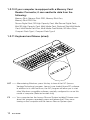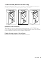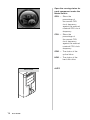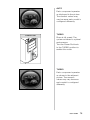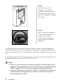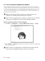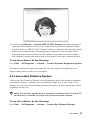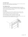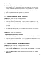
1
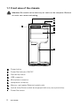
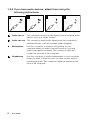
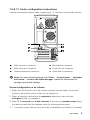
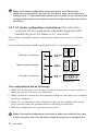
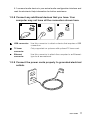
Machine type: 10062/7727 10073/1169 10066/7747 10067/7748 IdeaCentre K3 Series User Guide Version 5.0 2011.01 31048499 Important Safety Information Before using this manual, it is important that you read and understand all of the related safety information for this product. Refer to the Safety and Warranty Guide that you received with this product for the latest safety information. Reading and understanding this safety information reduces the risk of personal injury or damage to your product. Danger: Be aware of extremely hazardous or lethal situations. Attention: Be aware of possible damage to programs, devices, or data. Note: Pay attention to this important information. © Copyright Lenovo 2007, 2011. Contents Important Safety Information Chapter 1 Using the Computer Hardware............................... 1 1.1Front view of the chassis..........................................................2 1.2Rear view of the chassis...........................................................3 1.3Connecting your computer.......................................................6 1.4Power Dial (Selected models only)..........................................13 Chapter 2 Using the Rescue System..................................... 17 2.1OneKey Recovery...................................................................18 2.2Driver and Application Installation...........................................18 2.3System Setup.........................................................................19 2.4System Backup......................................................................20 2.5System Recovery...................................................................20 2.6Create Recovery Disc.............................................................20 Chapter 3 Using the Computer Software.............................. 21 3.1Lenovo Dynamic Brightness System.......................................22 3.2Lenovo Eye Distance System.................................................23 3.3BackOn Track.........................................................................24 Chapter 4 Troubleshooting and Confirming Setup............... 27 4.1Troubleshooting Display Problems..........................................28 4.2Troubleshooting Audio Problems............................................29 4.3Troubleshooting Software Problems.......................................29 4.4Troubleshooting Problems with Optical Drives and Hard Disks..............................................................................30 4.5Special considerations for troubleshooting Windows..............31 4.6Performing Daily Maintenance Tasks.......................................32 Contents 1 Chapter Using the Computer Hardware This chapter contains the following topics: 1 Computer hardware introduction Information on computer connections 2 Note: The descriptions in this chapter might be different from what you see on your computer, depending on the computer models and configurations. 3 4 User Guide 1 1.1Front view of the chassis Attention: Be careful not to block any air vents on the computer. Blocked air vents can cause overheating. 1 2 3 7 4 5 6 8 9 Power button Power Dial indicator ON/OFF File backup button USB connector Microphone connector Headphone connector Memory card reader (Selected models only) Optical drive (Some models are equipped with only one optical drive) Power Dial switch 2 User Guide 1.2Rear view of the chassis IdeaCentre K330 Voltage selection switch (Selected models only) Power connector PS/2 keyboard connector PS/2 mouse connector USB connectors (6) eSATA connector Ethernet connector Audio connectors (6) Standalone graphic card Expansion card slots (Access connectors for any installed PCI express cards) User Guide 3 IdeaCentre K330A/IedaCentre K330B Voltage selection switch (Selected models only) Power connector PS/2 keyboard connector PS/2 mouse connector HDMI connector USB connectors (4) On-board VGA connector Ethernet connector Audio connectors (3) Standalone graphic card (Selected models only) Expansion card slots (Access connectors for any installed PCI express cards) 4 User Guide IdeaCentre K335 Voltage selection switch (Selected models only) Power connector PS/2 keyboard connector PS/2 mouse connector eSATA connector USB connectors (6) HDMI connector On-board VGA connector Ethernet connector Audio connectors (6) Standalone graphic card (Selected models only) Expansion card slots (Access connectors for any installed PCI express cards) User Guide 5 1.3Connecting your computer Use the following information when connecting your computer. • Look for the small connector icons on the back of your computer. Match the connectors to the icons. • If your computer cables and connector panel have color-coded connectors, match the color of the cable end with the color of the connector. Note: Your computer may not have all of the connectors described in this section. 1.3.1Check the position of the voltage-selection switch on the rear of the computer. Use a ballpoint pen to slide the switch if necessary. Note: Some computers do not have a voltage switch. These computers control voltage automatically. • If the voltage supply range is 100-127 V AC, set the switch to 115 V. • If the voltage supply range is 200-240 V AC, set the switch to 230 V. 230 115 1.3.2Connect the keyboard cable to the appropriate keyboard connector (PS/2 connector or USB connector). 6 User Guide 1.3.3Connect the mouse cable to the appropriate mouse connector (PS/2 connector or USB connector). Note: If your computer is equipped with a wireless keyboard or mouse, follow the installation instructions for those devices. 1.3.4Connect the monitor cable to the monitor connector on the computer. • If you have a Video Graphics Array (VGA) Standard monitor, connect the cable to the connector as shown. Note: If your model has two monitor connectors, be sure to use the connector on the graphics adapter. • If you have an HDMI monitor, your computer must have an adapter that supports the HDMI monitor installed. Connect the cable to the port as shown. User Guide 7 1.3.5If you have audio devices, attach them using the following instructions. Audio line-in This connector receives audio signals from an external audio device, such as a stereo system. Audio line-out This connector sends audio signals from the computer to external devices, such as powered stereo speakers. 8 Microphone Use this connector to attach a microphone to your computer when you want to record sound or if you use speech-recognition software. This connector might be located on the front of the computer. Headphone Use this connector to attach headphones to your computer when you want to listen to music or other sounds without disturbing anyone. This connector might be located on the front of the computer. User Guide 1.3.67.1 Audio configuration instructions Use the following illustration when connecting a 7.1 surround sound audio system: Side surround connector Microphone connector Rear surround connector Front line-out connector Center/subwoofer connector Audio line-in connector Note: For more detailed settings, click Start → Control panel → Hardware and Sound → Lenovo HD Audio Manager. Follow the instructions to configure advanced settings. Sound configuration is as follows: 1. Right click the Sound icon in the system property bar and select the sounds option to setup the sounds in the pop-up dialog box. 2. Select a playback device from the playback dialog box, then click the configure button to configure it. 3. Select 7.1 surround from audio channels in the pop-up speaker setup dialog box and proceed with the speaker setup by following the prompts. 4. 7.1 surround sound can be used once this configuration procedure is complete. User Guide 9 Note: If the audio configuration interfaces above are different from those on your computer, you may use the above steps as a reference to configure the 7.1 surround sound audio device system in your actual audio configuration interface and read the electronic Help information for further assistance. 1.3.75.1 Audio configuration instructions: (This instruction is only for the pc model which mainboard supports audio transforming from 2.0 stereo to 5.1 surround.) This model of computer supports transforming stereo sound into 5.1 surround sound. Use the following guides when connecting to the 5.1 surround audio device: Blue line-in connector Surround Green line-out connector Front channel Pink Mic-in connector Center-LEF The configurations are as followings: 1. Right click the Sound icon in system property bar and select sounds option to setup the sounds in the pop-up dialog box. 2. Select a playback device from the playback dialog box, and then click configure button to configure it. 3. Select 5.1 surround from audio channels in the pop-up speaker setup dialog box to proceed with the speaker setup by following as prompted. 4. After the configuration, 5.1 surround can be used. Note: If the audio configuration interfaces in above are different from your actual computer, you may use above steps as reference to configure the 10 User Guide 5.1 surround audio device in your actual audio configuration interface and read the electronic Help information for further assistance. 1.3.8Connect any additional devices that you have. Your computer may not have all the connectors shown here. USB connector Use this connector to attach a device that requires a USB connection. TV tuner connector Only supported on systems with optional TV tuner card. Ethernet connector Use this connector to attach the computer to an Ethernettype local area network. 1.3.9Connect the power cords properly to grounded electrical outlets. User Guide 11 1.3.10If your computer is equipped with a Memory Card Reader Connector, it can read/write data from the following: Memory Stick, Memory Stick PRO, Memory Stick Duo, Memory Stick PRO Duo. Secure Digital Card, SD High Capacity Card, Mini Secure Digital Card, Mini SD High Capacity Card, Multi Media Card, Reduced Size Multi Media Card, Multi Media Card Plus, Multi Media Card Mobile, XD Micro Drive, Compact Flash Type I, Compact Flash Type II 1.3.11Keyboard and Mouse (wired) LV T LV T LVT ——After entering Windows, press this key to launch the LVT (Lenovo Vantage Technology) program, Lenovo’s pre-loaded Home PC software. In addition to its own functions, the LVT program will allow you to start other Windows compatible software, specially configured to run on this model of computer. (Selected models only) F2 ——Your computer has the Lenovo Rescue System installed.To learn more about this program, repeatedly press and release the F2 key once turning on the computer until the Lenovo Rescue System open. 12 User Guide 1.4Power Dial (Selected models only) The Power Dial feature allows your computer to switch to different modes, thus providing you with customized experiences during operations. TURBO mode COOL mode AUTO mode O RB TU TO AU L O CO Operation of the Power Dial The Power Dial function supports three operating modes: AUTO TURBO and COOL. System resources are optimized by toggling between those three different modes. Different modes are used for different applications. Display the main screen of the software Double click the Power Dial icon in the Quick Launch bar. User Guide 13 Open the running status for each component under the Mode Switch: GPU — Show the percentage of the current GPU clock frequency against the nominal maximal GPU clock frequency. CPU — Show the percentage of the current CPU clock frequency against the nominal maximal CPU clock frequency. ODD — The status of the optical drive. HDD — The status of the hard disk drive. AUTO mode TO AU 14 User Guide AUTO AUTO Each component operates as displayed in the picture. The numeric values may vary because each model is configured differently. TURBO mode TURBO Runs at full speed. The system achieves its optimal performance. Turn the Power Dial knob to the TURBO position to enable this mode. O RB TU TURBO Each component operates as shown in the adjacent picture. The numeric values may vary because each model is configured differently. User Guide 15 COOL COOL mode The CPU runs at low frequency. The system consumes minimum power. Turn the Power Dial knob to the COOL position to enable this mode. L O CO COOL Each component operates as shown in the adjacent picture. The numeric values may vary because each model is configured differently. If other applications such as the burner program or game software change the parameter settings for COOL mode when it is launched, a prompt dialog box will pop up indicating that your “COOL settings” have been changed. In this case, click OK. To restore the previous COOL mode settings, exit other applications then turn the Power Dial knob mounted on the chassis to COOL. Notes: • When you are running system-intensive games or other programs that consume a high proportion of the system resources, you should choose TURBO mode. This will allow you to achieve optimal performance. • When the ODD status is shown as “QUIET”, it indicates that the current maximal data CD reading speed is lower than the nominal maximal reading speed of the ODD. 16 User Guide Chapter Using the Rescue System This chapter contains the following topics: 1 OneKey Recovery Driver and Application Installation System Setup System Backup System Recovery Create Recovery Disc 2 Attention: Using this program will result in loss of data. • You can restore the C: drive of the computer to factory default settings or to the last system backup status using OneKey Recovery. If you do this, all of the existing data on drive C: will be lost, but the content and format of the other partitions of the hard disk drive will remain unchanged. • If you want to install an operating system and back it up with OneKey Recovery, you must format the C: partition in NTFS format and install the operating system on the C: partition. Otherwise, the OneKey Recovery system cannot run. 3 4 User Guide 17 Note about the service partition: The files and relevant data used by the rescue system are saved in the service partition. Deleting this partition will make the rescue system unusable. For more detailed information, see the following instructions: By selecting Control Panel → Administrative Tools → Computer Management → Disk Management, you can see the service partition, which must not be deleted. Note: The recovery files and relevant data used by the rescue system are saved in the service partition. If the service partition is deleted or damaged by someone other than authorized Lenovo service personnel, Lenovo will not be liable for any losses arising therefrom in any way. 2.1OneKey Recovery OneKey Recovery is an easy-to-use application. You can use it to restore your computer to the system default or to a previously backed up state. Detailed Operation Procedure 1. Repeatedly press and release the F2 key once turning on the computer until the Lenovo Rescue System open, then select OneKey Recovery. Note: System Recovery will overwrite all of the data on the C: drive. To prevent loss of data, be sure to back up relevant data before performing system recovery. 2. Follow the on-screen instructions to select the backup task you want to restore from and the disk where you want to install the operating system, then press Next to start the restore. 3. Please wait during the process of system recovery. Do not interrupt the operation during the recovery process. 4. After the system is recovered successfully, the software will prompt you to restart the computer. Restart the computer and start the operating system. 2.2Driver and Application Installation The Driver and Application Installation function in the rescue system provides a way for the user to conveniently reinstall all of the Lenovo applications and drivers that were shipped with your Lenovo hardware. 18 User Guide Method 1: Automatic Installation Repeatedly press and release the F2 key once turning on the computer until the Lenovo Rescue System open, then select Drivers and Application Installation. Follow the on-screen prompts to install the Lenovo drivers and applications. Click Install to start installing the Lenovo Drivers and Application Installation software. The system will restart. After the system has restarted, the installation process will continue until it has completed. Method 2: Manual Installation In the Windows system, Click Start → All Programs → Lenovo → Lenovo Drivers and Application Installation. After starting the procedure, install all the drivers and software manually by following the prompts. Notes: 1. Do not install software which is already installed on the computer. 2. Make sure that the Drivers and Application Installation software has been automatically installed before starting the operating system. The manual installation function can only be used after the software has been installed. 2.3System Setup System Setup configures the network configuration for the Lenovo Rescue System to ensure your Rescue System can connect to internet. In addition, System Setup sets and manages all passwords for the Lenovo Rescue system. 2.3.1Launch Repeatedly press and release the F2 key once turning on the computer until the Lenovo Rescue System open, then select System Setup. 2.3.2Network Settings Depending on the network access mode of the computer, select “ADSL” or “LAN Connection” in the network connection modes. 1. If you select “ADSL” input the username and password of the ADSL connection. User Guide 19 2. If you select “LAN connection” configure the IP address and proxy server of the LAN. 2.3.3Password Management Password Management allows you to set and manage the password for Lenovo Rescue System. The default password is blank. Set a password when you access Password Management for the first time. If you don’t want to set a password, access the system directly and operate it accordingly. 2.4System Backup This backs up your system partition to an image file. In case of a system failure, you can restore your system from this image file. In the Windows system, click Start → All Programs → Lenovo → Lenovo Rescue System. After starting Rescue System, click System Backup to back up your system partition by following the prompts. 2.5System Recovery Reboot your computer into the system recovery environment. You can choose to restore to a system backup point or the initial state (factory default settings). 2.6Create Recovery Disc Create a bootable recovery disc from the current system. These recovery discs are used to boot your computer and will guide you through the entire restoration process. In the Windows system, click Start → All Programs → Lenovo → Lenovo Rescue System. After starting Rescue System, click Create Recovery Disc to create a bootable recovery disc from the current system. Follow the on-screen prompts to create recovery discs. 20 User Guide Chapter Using the Computer Software This chapter contains the following topics: 1 Computer software instructions Note: The interface and function of each of these features are subject to the actual software that was shipped with the computer model that you purchased. 2 3 4 User Guide 21 3.1Lenovo Dynamic Brightness System Lenovo Dynamic Brightness System can automatically detects the surrounding ambient brightness and adjusts the display brightness accordingly. This allows you to set the screen brightness to a comfortable level for different environments. You can also set the display delay time to automatically turn off the display when you are away from the computer. Note: The Auto Switch Display function can not be used when your computer is in standby mode, sleep mode or turned off. Note: This function applies only to computers equipped with a Lenovo PC camera and is available only after the camera has been installed. Before using this software, do the following: 1) Click Start → All Programs → Lenovo USB2.0 UVC Camera → vmcap. 2) Select Options → Preview from the pop-up window to display the image in the video capture window. Note: If there is no image display in the AMCAP video capture window, please confirm that preview has been selected in the options. 22 User Guide 3) Confirm that Devices → Lenovo USB 2.0 UVC Camera has been selected. If there are other devices in this option, make sure they are not selected. When only the “Lenovo USB 2.0 UVC Camera” device is selected, the window should display the camera image. The image being captured by the camera will be displayed in the video capture window. Adjust the position and pitch angle of the camera to ensure the whole face is displayed in the video capture window. To use this software, do the following: Click Start → All Programs → Lenovo → Lenovo Dynamic Brightness System. The default setting has been pre-selected. You can adjust the brightness and display delay time according to your needs. 3.2Lenovo Eye Distance System The Lenovo Eye Distance System can automatically detect the distance between you and the display. It will alert you automatically when you sit too close to the display. You can also set the viewing distance as well as a time interval after which a warning will pop up. Note: This function applies only to computers equipped with a Lenovo PC camera and is available only after the camera has been installed. To use this software, do the following: Click Start → All Programs → Lenovo → Lenovo Eye Distance System. User Guide 23 The default setting has been pre-selected. You can adjust the viewing distance according to your needs. Note: 1. Ensure the lens of the camera is clearly visible and not covered. 2. Ensure your eyes are clearly visible and not covered. (The function that detects the distance between the user and monitor is based on the position of the user’s eyes. Therefore, if the eyes are covered or there is a strong reflection, distance detection may be affected.) Wearing glasses may affect the accuracy of the face image verification. 3. The limits for distance detection by the camera: Minimum distance: approx. 20 centimters (7.90 inches) Maximum distance: approx. 70 centimeters (27.55 inches) Pitch angle (angle of rotation of the face in the vertical plane): Elevation: 20 degrees Depression: 30 degrees Horizontal angle of rotation (angle of rotation of the face in the horizontal plane): between -20 and +20 degrees 3.3BackOn Track BackOn Track lets you easily back up important files to a disc, hard drive, or other storage device. A Back Up Files project can be scheduled to run daily, weekly, or monthly. Large backups are automatically spread across as many discs as you need. 3.3.1Using BackOn Track Choose All Programs → Lenovo → FileBackup from the Start menu to launch the BackOn Track software. 3.3.2Back up files Begin by selecting the drive, drive partition, or folder containing the files you want to back up. You can choose to archive all the files in the selected path or just certain types of files. You can back up any files that have changed since a specified date, or create a custom backup based on certain file extensions. Finally, schedule the project to run on a regular basis, or begin backing up right away. 24 User Guide 3.3.3My Project My projects is used to manage your saved backup projects. Any backup projects that you have saved will be listed under My Projects. 3.3.4Restore Files The Restore Files project restores individual files and folders that you have protected using a Back Up Files project. With Restore Files, you select a backup, search for the file or folder you would like to restore, and then click Next. The files will be restored to the location you choose. 3.3.5Help For more information on the operation of BackOn Track, see Product Help Information in the Help option. You can learn more about the operation and settings of BackOn Track software in the Help document. 3.3.6File Backup button (selected models only) After starting the Windows operating system, press the File Backup button on the top of the chassis to launch the BackOn Track software. User Guide 25 26 User Guide Chapter Troubleshooting and Confirming Setup This chapter contains the following topics: 1 Troubleshooting and Problem Resolution Note: The description of the TV tuner card in this manual is only used for the machines which have the TV tuner card. It does not apply to those machines that do not have a TV tuner card. 2 3 4 User Guide 27 Solving Problems Follow these tips when troubleshooting your computer: • If you added or removed a part before the problem started, review the installation procedures to ensure that the part is correctly installed. • If a peripheral device does not work, ensure that the device is properly connected. • If an error message appears on the screen, write down the exact message. This message may help support personnel diagnose and fix the problem(s). • If an error message occurs in a program, see the program’s documentation. Note: The procedures in this document were written for the Windows default view, so they may not apply if you set your Lenovo® computer to the Windows Classic view. 4.1Troubleshooting Display Problems Problem: Blank screen or no image is displayed on the monitor. Troubleshooting and problem resolution: 1. Check to see if the monitor has been turned on; if not, press the Power button. 2. Check to see if the monitor power cord is loose; if so, plug the power cord securely into the monitor. 3. Check to see if the signal cable to the monitor is securely connected to the connector on the computer graphics card; if not, shut down the computer then connect the signal cable of the monitor securely to the connector on the computer graphics card. Problem: You need to change the display property settings. Setting display background and icon properties: 1. Right-click the desktop anywhere except over an icon, then select Personalize from the pop-up menu. 2. From here, select the appropriate options to: • Change the desktop background • Select a screen saver • Select colors and appearance options for icons and text • Set resolution and colors in the Display Settings options 28 User Guide Problem: Ripple on screen. Troubleshooting and problem resolution: 1. Check to see if any of the following devices are located less than one meter from the computer: refrigerators, electric fans, electric dryers, UPS systems, regulators, fluorescent lamps or other computers that may be generating magnetic interference. 2. Move any interfering devices away from the computer. 3. If the problem persists, contact Lenovo Service. 4.2Troubleshooting Audio Problems Problem: No sound from the integrated speakers. Troubleshooting and problem resolution: • Adjust the Windows volume control — double-click the speaker icon in the lower-right corner of your screen. Ensure that the volume is turned up and the sound is not muted. Adjust the volume, bass, or treble controls to eliminate distortion. • Reinstall the audio driver. • Disconnect any headphones from the headphone connector — sound from the speakers is automatically disabled when headphones are connected to the computer’s side-panel headphone connector. Problem: No sound from headphones. Troubleshooting and problem resolution: • Check the headphone cable connection — ensure that the headphone cable is securely inserted into the headphone connector. • Adjust the Windows volume control — click or double-click the speaker icon in the lower-right corner of your screen. Ensure that the volume is turned up and the sound is not muted. 4.3Troubleshooting Software Problems Problem: You are unable exit a running program normally. Troubleshooting and problem resolution: 1. Open the Task Manager window by pressing Ctrl, Alt and Delete at the same time. 2. Select the Application tab, select the problem program, then click the End Task button. User Guide 29 Problem: You need to install or uninstall a program. Problem resolution: During installation never abort the install process by powering the system off or through other drastic means. This can cause system program disorder or even failure during system initialization. During the uninstall process, never directly delete the files or folders. This is harmful to the system, and might cause a system-wide malfunction. Use the following procedure to properly uninstall programs: 1. Back up all documents and system settings related to the program before removing it. 2. If the program has its own uninstaller, run it directly to uninstall the program. 3. If the program does not have its own uninstaller, then select Control Panel from the Start menu. 4. From the Control Panel, choose Programs and Functions. 5. Find the applicable program from the Programs and Functions dialog box and then select Uninstall/Modify. 6. Perform the instructions displayed to uninstall the software. 4.4Troubleshooting Problems with Optical Drives and Hard Disks Problem: The Optical drive is unable to read a CD/DVD. Troubleshooting and problem resolution: 1. Check to determine if there is an optical drive icon in the resource manager of the operating system. If not, restart your computer. If there is still no icon, contact Lenovo Service. Otherwise, continue with the next step of this procedure. 2. Confirm that the CD/DVD has been properly placed in the drive. If not, reload the CD or DVD. Otherwise, continue with the next step of this procedure. 3. Check the specifications that came with your computer to confirm that this optical drive is capable of reading this type of CD or DVD. 4. If the CD/DVD cannot be read, replace it with a known good CD/DVD such as one that was shipped with the computer. 5. If the known good CD cannot be read, visually check the operating side of the CD/DVD for defects. 30 User Guide Problem: The capacity of the hard disk, as indicated by the system, is less than the nominal capacity. Troubleshooting and problem resolution: For computers equipped with the OneKey Recovery feature, the system recovery feature needs to occupy some hard disk space. This may account for the apparent hard disk capacity deficit. Further Technical Explanation: The nominal capacity of the hard disk is expressed in the decimal system, 1000 bytes. But the actual hard disk capacity is expressed in the binary system as 1024 bytes (For example, the nominal capacity 1G is 1000M, while the actual capacity 1G is 1024M). The capacity of the hard disk shown in Windows can be calculated according to the calculations in the following example: The nominal capacity of the hard disk is 40G, while its actual capacity should be: 40 x 1000 x 1000 x 1000/(1024 x 1024 x 1024) = 37G. If the Service partition of 3G - 3 x 1000 x 1000 x 1000/(1024 x 1024 x 1024) = 2.79G is subtracted, the capacity of the hard disk shown in the system can be obtained. The capacity of the hard disk as calculated using this method may be slightly different from the actual capacity due to the rounding of totals. 4.5Special considerations for troubleshooting Windows Record the following information as it may be useful later when troubleshooting system problems: 1. The serial number of the software. The serial number was shipped with the computer and provided separately by the manufacturer. The Help Center is unable to retrieve this number. 2. The drivers for this computer model only support the Windows 7 system. 3. When you use the Windows Media Center to watch TV, be particularly attentive to the following: • In the following two situations, you must re-save a channel list: a. When you change your TV signal from digital to analog, your saved channel list for digital TV is deleted. When you want to watch digital TV again, you must create and save a new channel list. b. When you change your TV signal from analog to digital, your saved channel list for analog TV is deleted. When you want to watch analog TV again, you must create and save a new channel list. User Guide 31 • You must set the TV tuner input signal to analog before you can watch Teletext programming. 4.6Performing Daily Maintenance Tasks Cleaning the computer components Because many of the computer components consist of sophisticated integrated circuit boards, it is very important to periodically clean the computer to prevent dust buildup. The cleaning supplies you need to clean the components include: a vacuum cleaner, a soft cotton cloth, clear water (preferably purified or distilled water) and cotton swabs. Attention: Before you clean your computer, disconnect the computer from the electrical outlet. Clean your computer with a soft cloth dampened with water. Do not use liquid or aerosol cleaners, which may contain flammable substances. Note: To avoid damaging the computer or display, do not spray cleaning solution directly onto the display. Only use products specifically designed for cleaning displays, and follow the instructions included with the product. The following are general methods for cleaning the components: • You can use a soft cloth to remove dust on the surface of the computer, the monitor, the printer, the speakers and the mouse. • You can use a vacuum cleaner to clean in otherwise inaccessible corners. • To clean the keyboard thoroughly, shut down the computer and scrub it gently with a wet cloth. Do not use the keyboard until it is dry. Do not do any of the following: • Allow water to enter the computer. • Use a heavily dampened cloth. • Spray water directly onto the surface of the monitor or inside the computer. LCD monitors should be cleaned daily. Use a dry cloth to brush dust from the monitor and keyboard every day. Keep all surfaces clean and free of grease stains. 32 User Guide