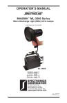
1
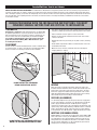
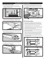
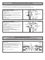
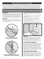
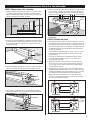
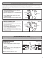
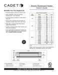
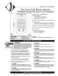
The Cadet
Electric Baseboard
OWNER’S GUIDE
240/208 VOLT MODELS
2F350
6F1500
2F500
8F2000
3F750
8F2500
4F1000
8F2025
5F1250
10F2500
Features & Benefits
•
•
•
•
•
Oversized high temperature limit switch with full
length sensor for added safety
Durable steel sheathed element with a limited
lifetime warranty
Easy installation with pre-punched case at 1” intervals
Rugged steel construction
Thermostat not included
208 VOLT MODELS
2F500-8
3F750-8
5F1250-8
6F1500-8
8F2500-8
4F1000-8
8F2000-8
120 VOLT MODELS
2F500-1
3F750-1
6F1500-1
4F1000-1
TOOLS REQUIRED
• #2 Phillips
Screwdriver
• Straight
Screwdriver
• Wire Strippers
• Drill or Hammer
Drill Bits
(4) Wood Screws
• Wire Connectors
• (1) Strain Relief
Connector
•
•
IMPORTANT INSTRUCTIONS
1.
2.
3.
4.
5.
6.
7.
8.
WARNING!
9.
WARNING
Overheating or fire may occur. Do not install the heater behind doors.
Turn the electrical power off at the electrical
panel board (circuit breaker or fuse box) and 10.
WARNING
lock or tag the panel board door to prevent
Fire or explosion may occur. Heater has hot and arcing or sparking
someone from turning on power while you are
parts inside. Do not install heater in any area where combustible
working on the heater. Failure to do so could
vapors, gases, liquids, or excessive lint or dust are present.
result in serious electrical shock, burns, or
11.
WARNING
possible death.
Burn Hazard. This heater is hot when in use. To avoid burns, do
not let bare skin touch hot surfaces. Use extreme caution when
Read all instructions before using this heater.
any heater is used by or near children or invalids and whenever
Read all information labels. Verify that the electrical supply
the heater is left operating unattended.
wires are the same voltage as the heater.
All electrical work and materials must comply with the 12.
WARNING
Risk of electrical shock. Keep all foreign objects out of heater.
National Electric Code (NEC), the Occupational Safety and
Do not operate after heater malfunctions or has been dropped
Health Act (OSHA), and all state and local codes.
or damaged in any manner.
The heater must be grounded to the grounding pigtail (copper
wire) provided.
13.
WARNING
If you need to install a new circuit or need additional wiring
Risk of Fire. Do not block heater. Heater must be kept clear of
information, consult a qualified electrician.
all obstructions: minimum of 12 inches in front and above,
Protect electrical supply from kinks, sharp objects, oil, grease,
6 inches on both sides. Heaters must be kept clean of excessive
hot surfaces or chemicals.
lint, dirt and debris. (See Maintenance Instructions)
Do not place heater against paperboard or low-density 14.Use this heater only as described in this manual. Any other use
cellulose fiberboard surfaces.
not recommended by the manufacturer may cause fire, electrical
Do not place heater below an electrical convenience receptacle.
shock, or injury to persons.
SAVE THESE INSTRUCTIONS
www.cadetco.com
Tel: 360-693-2505
P.O. Box 1675
Vancouver, WA
98668-1675
Installation Instructions
ABOUT THE CADET ELECTRIC BASEBOARD: The Cadet Electric Baseboard is designed to provide zonal heat to a room by using convection to
naturally circulate warm air. Safety is Cadet’s first priority. All F-Series electric baseboards feature an oversized high temperature limit switch
with a full length capillary sensor tube that temporarily shuts the heater off when excessive operating temperatures are detected. For effective
and safe operation, and to prolong the life of the heater, read all instructions and safety information, and follow the maintenance instructions
in this Owner’s Guide.
BEFORE PROCEEDING WITH THE INSTALLATION INSTRUCTIONS, YOU MUST
CONSIDER SEVERAL FACTORS THAT ARE CRITICAL TO INSTALLATION
THERMOSTAT
A thermostat is required. A Cadet wall thermostat is recommended
for optimum performance, or you may prefer the convenience of a
built-in thermostat kit. For instructions on wiring a thermostat, see
the instructions that were included with your thermostat. If you
are installing a wall thermostat, refer to the section later in this
guide titled “Baseboard Wiring With a Wall Thermostat” prior
to installing the baseboard.
PLACEMENT
For best results, install the baseboard heater under a window, along
an outside wall, or as close as possible to an outside door. Follow
these instructions for selecting an ideal area of installation:
DO NOT INSTALL ANY BASEBOARD
BELOW AN ELECTRICAL OUTLET
•
The seam at the junction of the wall and floor behind the heater may
need to be caulked to prevent dust from being drawn into the room.
•
Heater should be set flush against surface of the wall.
•
Remove any obstructions between the back of the unit and the
surface of the wall.
•
Baseboard heater may sit directly on any floor surface, including
carpet.
•
Do not allow carpet to block lower air intake located 1 inch from
the bottom of the heater.
•
Maintain at least 12 inches minimum clearance from objects
hanging above (i.e. drapes).
WIRING
Wire connection is possible from either right or left side of the
baseboard heater. Determine which side of the baseboard you are
making wire connections by locating the supply wires. You must
locate the supply wires before mounting the heater. See section
titled “Baseboard Wiring With a Wall Thermostat” prior to wiring
the baseboard if you are installing a wall thermostat.
VOLTAGE (ALL MODELS)
It is extremely important that you verify the electrical supply wires
are the same voltage as the heater (i.e. 120 volt heater to 120 volt
power supply and 240 volt heater to 240 volt power supply). If
replacing an existing heater check the labels of the old heater and
replace using same voltage. Hooking a 240 volt heater to a 120 volt
power supply will drastically reduce the heater’s output. Hooking
a 120 volt heater to a 240 volt power supply will destroy the heater.
WATTAGE (FOR MODEL 8F2025)
DO NOT INSTALL ANY BASEBOARD VERTICALLY.
MOUNT THE BASEBOARD HORIZONTALLY ONLY
2
Model 8F2025 is a multi-watt unit configured for either 2500 or 2000
watts. The heater is factory set for 2500 watts, but the instructions
vary depending on your desired wattage and which side you are
wiring. Make sure you follow the directions in the Owner’s Guide
for your specific application. It is best to decide on your desired
wattage prior to installing the baseboard.
Installation Instructions
STEP 1: Mount Heater to Wall
1. Locate wall studs closest to supply wires and position heater
(See Figure 1). NOTE: Wire connection is possible from either right
or left side of the baseboard heater.
5. Mount the heater securely to the wall with nails or screws going
into at least two wall studs (See Figure 5). The back of the heater
has “star punch” dimples that allow nails or screws to easily pierce
the sheet metal.
Figure 5
Figure 1
SUPPLY
STUDS
FINISHED
WALL
MOUNT
SECURELY
TO WALL
STUDS
WIRING
COMPARTMENT COVER
FLOOR
2. Remove the wiring compartment cover by removing the screw
(See Figure 2). The wiring compartment is an approved junction
box for the baseboard only. No additional junction box is required.
Figure 2
WIRING
COMPARTMENT
COVER
3. Remove the slotted knockout closest to the supply wires and install
a strain relief connector (See Figure 3).
Figure 3
NOTE: You do not need to disassemble any additional parts to mount
the heater.
STEP 2: Baseboard Wiring
1. Verify the electrical supply wires are the same voltage as the
heater. Check heater specifications to ensure correct wiring.
Failure to do so may destroy the heater and void your warranty.
Both 120 volt and 240 volt baseboard wiring utilize 3 supply wires.
120 volt baseboard wiring: 1 hot, 1 neutral and 1 ground
240 volt baseboard wiring: 2 hot and 1 ground. No neutral needed.
For all baseboard wiring applications, both supply wires must be
connected to at least one (1) heater wire.
2. Connect the grounding lead to the grounding pigtail (copper wire)
with a connector (See Figure 4). It may be necessary to move ground
lead to the side you are wiring.
3. Disconnect one factory connector (See Figure 6. Model 8F2025 see
Figure 7). If wiring on the left side, disconnect factory connector
A. If wiring on the right side, disconnect factory connector B.
NOTE: There are no loose wires provided with the baseboard.
This is due to the ability to wire the baseboard on either the right
or left side of the heater.
A
B
Figure 6
4. Pull supply wires through the connector and secure leaving 6 inch
wire leads for later use (See Figure 4).
Figure 4
DO NOT DISCONNECT
GROUND
JUNCTION BOX
A
B
SUPPLY
WIRES
GROUND
WIRE
Figure 7
Model
8F2025
Only
GROUNDING PIGTAIL
WIRE CONNECTOR
DO NOT DISCONNECT
GROUND
4. Proceed to the next step.
3
Installation Instructions
STEP 2: Baseboard Wiring (continued)
Refer to the wiring diagram below that corresponds to your heater application.
For single wattage baseboards, refer to “Standard Baseboards.”
For model 8F2025, refer to “Multi-Watt Baseboards.”
STANDARD BASEBOARD WIRING ON RIGHT SIDE
Baseboard Heater
120V OR 240V SUPPLY (See Figure 8)
1. Connect one supply wire to one heater wire.
2. Connect remaining supply wire to remaining heater wire.
3. Replace wiring compartment cover and secure with screw
previously removed.
4. Turn power back on at the electrical panel board.
Figure 8
Right Side
Wiring Shown
To Supply
Supply Wires
Side ‘B’ Shown
Ground
To Supply
STANDARD BASEBOARD WIRING ON LEFT SIDE
120V OR 240V SUPPLY (See Figure 9)
1. Connect one supply wire to one heater wire.
2. Connect remaining supply wire to remaining heater wire.
3. Replace wiring compartment cover and secure with screw
previously removed.
4. Turn power back on at the electrical panel board.
Supply Wires
Figure 9
Left Side
Wiring Shown
Baseboard Heater
Side ‘A’ Shown
Ground
Figure 10
Right Side
Wiring Shown
MULTI-WATT BASEBOARDS: WIRING ON RIGHT SIDE
MODEL 8F2025 (See Figure 10)
1. Connect one supply wire to one heater wire.
2. Connect remaining supply wire to remaining heater wire.
3. Replace wiring compartment cover and secure with screw
previously removed.
4. Selecting desired wattage
a. For 2500 watt applications: No action is required.
Heater is factory set for 2500 watts.
b. For 2000 watt applications: Remove left wiring compartment
cover. Cut red wire and cap both loose ends with
approved wire connectors, or wrap both loose ends with
electrical tape. Replace wiring compartment cover and
secure with screw previously removed.
5. Turn power back on at the electrical panel board.
MULTI-WATT BASEBOARDS: WIRING ON LEFT SIDE
MODEL 8F2025 (See Figure 11)
1. Connect one supply wire to one heater wire.
2. Connect remaining supply wire to remaining heater wire.
3. Selecting desired wattage
a. For 2500 watt applications: No action is required.
Heater is factory set for 2500 watts.
b. For 2000 watt applications: Cut red wire and cap both loose
ends with approved wire connectors, or wrap both loose
ends with electrical tape.
4. Replace wiring compartment cover and secure with screw
previously removed.
5. Turn power back on at the electrical panel board.
Red
Wire
Red Wire
Baseboard Heater
To Supply
Supply Wires
Side ‘B’ Shown
Ground
2000 Watt Configuration
Left Side of Baseboard Shown
To Supply
Supply Wires
Red Wire
Side ‘A’ Shown
Ground
Baseboard Heater
Model 8F2025 Factory set for
2500 watts
Red
Wire
Figure 11
Left Side
Wiring Shown
Red
Wire
2000 Watt Configuration
Left Side of Baseboard Shown
4
Baseboard wiring with a wall thermostat - Optional
Refer to the wiring diagram below that corresponds to your thermostat application. Note: Wiring diagrams are for reference only.
See wall thermostat instructions included with your thermostat for your specific application.
For instructions on wiring using an in-built thermostat, see Cadet BTF1, BTF2 and SBFT2 Installation Instructions
SINGLE POLE WALL THERMOSTAT
1. Route supply wires to the thermostat wiring box (if not
already present).
2. Connect one supply wire to one thermostat wire (typically
marked L1).
3. Route remaining thermostat wire (typically marked T1)
to the baseboard heater.
4. Route remaining supply and ground wire to the baseboard
heater.
5. Follow installation instructions for mounting and wiring
baseboard heater.
DOUBLE POLE WALL THERMOSTAT
1. Route supply wires to the thermostat wiring box (if not
already present).
2. Connect one supply wire to one thermostat wire (typically
marked L1).
3. Connect remaining supply wire to other thermostat wire
(typically marked L2).
4. Route remaining thermostat wires (typically marked T1
and T2) to the baseboard heater.
5. Route ground wire to the baseboard heater.
6. Follow installation instructions for mounting and wiring
baseboard heater.
To Supply
Figure 12
L1
Thermostat
wiring box
Ground
Single Pole
Thermostat
LOW
T1
To Heater
To Supply
Figure 13
Thermostat
wiring box
L2
L1
Ground
Double Pole
Thermostat
OFF
T1
To Heater
T2
Multiple Baseboard Wiring - Optional
Follow the instructions below if you are wiring more than one heater in parallel on same circuit.
If you are wiring multiple baseboards to one control, it is recommended that you use one control per room.
MULTIPLE BASEBOARD WIRING. 240V SUPPLY ONLY
(See Figure 14)
1. Left side wiring: disconnect factory connector A. Right
side wiring: disconnect factory connector B.
2. Connect one wire from each heater to one supplyBwire.
3. Connect remaining wire from each heater to the
remaining supply wire.
4. Connect supply ground wire to both ground leads.
Figure 14
STANDARD
BASEBOARDS
SHOWN
To Wall Thermostat
Baseboard Heater
Right Side
A
Baseboard Heater
Left Side
B
Note: Field wiring is not provided
A
Heater Wires
Field Wiring
Ground
Do not disconnect
5
Operation & Maintenance
How To Operate Your Heater
Maintenance
1. Switch the power on at the electrical panel board. PLEASE NOTE:
Upon initial start-up, the heater may emit a burning odor. This
is not dangerous, and is due to a protective lubricant used
during the manufacturing process. It typically dissipates within
several hours.
2. Turn the thermostat fully clockwise.
3. When the room reaches your comfort level, turn the thermostat
knob counterclockwise until a clicking sound is heard (if using
a digital thermostat, set at desired room temperature). The
baseboard will automatically cycle around this preset temperature.
Cadet electric baseboards are virtually maintenance-free. However,
a certain amount of lint and dust will accumulate inside the unit
and should be periodically cleaned:
1. Turn the electrical power off at the electrical panel board (circuit
breaker or fuse box) and lock or tag the panel board door to
prevent someone from turning on power while you are working
on the heater. Failure to do so could result in serious electrical
shock, burns, or possible death.
2. Vacuum inside the unit, being careful not to damage the aluminum
fins on the heat exchanger.
Troubleshooting Chart
CONSULT LOCAL ELECTRICAL CODES TO DETERMINE WHAT WORK MUST BE PERFORMED BY QUALIFIED ELECTRICAL SERVICE PERSONNEL
Symptom
Problem
Solution
1. Unit may have a loose end plate
2. Heater may not be mounted properly
1. Loosen end plate screws ¼ turn after allowing heater to warm, move end
plate back and forth, then tighten
2. Loosen heater from wall by turning mounting screws ¼ turn
Heater not working
1. Heater does not have proper voltage
to function correctly
2. Loose wire connections
3. Incorrect circuit breaker
4. Defective limit
1. Check voltage at the heater between supply wires and make sure it
matches required heater voltage
2. Tighten any loose wire connections
3. Circuit breaker positioned incorrectly - relocate breaker
4. Replace limit
Heater will not shut off
1. Heat loss from room is greater than
heater capacity
2. Defective thermostat
1. Close doors and windows. Provide additional insulation, install a higherwattage heater or multiple heaters if necessary
2. Adjust thermostat to its lowest setting. If heater continues to run
(allow two minutes for the thermostat to respond), replace thermostat
3. Refer to thermostat documentation and correct wiring
4. Change thermostat to double pole model with positive off (single pole
thermostats have a minimum temperature setting with no “off” position).
Snapping noise
3. Thermostat wired incorrectly to heater
4. Temperature in room lower than
thermostat’s lowest setting
Black streaks (sooting)
depositing on baseboard,
walls, and drapes
1. Excessive hydrocarbons present in
home environment*
2. Not enough fresh air flowing through
baseboard
3. Streaking being allowed to build up
on room surfaces
1. Remove/reduce use of items emitting hydrocarbons. (Common sources:
insect foggers, aerosol sprays, carpet cleaning chemicals, candles, plants,
dust, cigarette smoke and fireplaces)
2. Increase amount of fresh air available in room. Do not use heater during
any chemical usage (insect fogging, carpet cleaning, etc.) and allow for
outside air exchange before re-use of heater(s)
3. More frequent cleaning of streaking to reduce amount of build-up
* Black soot and residue is formed by the combustion of hydrocarbons. Existing hydrocarbons in environment pass through heater element and scorch,
exit the heater and deposit on walls and room surfaces. Note: The heater itself does not produce/release any hydrocarbons.
WARRANTY
Maintenance: For more effective and safer operation and to prolong
the life of the heater, read the Owner’s Guide and follow the maintenance instructions included with each heater. Failure to properly
maintain the heater will void any warranty and may cause the
heater to function improperly. Warranties are non transferable and
apply to original consumer only. Warranty terms are set out below.
LIMITED LIFETIME WARRANTY: Cadet will repair or replace any
Cadet baseboard (F) element found to be defective at any time.
THESE WARRANTIES DO NOT APPLY:
1. Damage occurs to the product through improper installation or
incorrect supply voltage;
2. Damage occurs to the product through improper maintenance,
misuse, abuse, accident, or alteration;
3. The product is serviced by anyone other than Cadet;
4. If the date of manufacture of the product cannot be determined;
5. If the product is damaged during shipping through no fault
of Cadet.
6. CADET’S WARRANTY IS LIMITED TO REPAIR OR REPLACEMENT
AS SET OUT HEREIN. CADET SHALL NOT BE LIABLE FOR DAMAGES SUCH AS PROPERTY DAMAGE OR FOR CONSEQUENTIAL
DAMAGES AND/OR INCIDENTAL EXPENSES RESULTING FROM
BREACH OF THESE WRITTEN WARRANTIES OR ANY EXPRESS
OR IMPLIED WARRANTY.
7. IN THE EVENT CADET ELECTS TO REPLACE ANY PART OF YOUR
CADET PRODUCT, THE REPLACEMENT PARTS ARE SUBJECT TO THE
6
SAME WARRANTIES AS THE PRODUCT. THE INSTALLATION OF
REPLACEMENT PARTS DOES NOT MODIFY OR EXTEND THE UNDERLYING WARRANTIES. REPLACEMENT OR REPAIR OF ANY CADET
PRODUCT OR PART DOES NOT CREATE ANY NEW WARRANTIES.
8. These warranties give you specific legal rights, and you may also
have other rights which vary from state to state. Cadet neither
assumes, nor authorizes anyone to assume for it, any other obligation or liability in connection with its products other than as set
out herein.
If you believe your Cadet product is defective, please, contact
Cadet Manufacturing Co. at 360-693-2505, during the warranty period,
for instructions on how to have the repair or replacement
processed. Warranty claims made after the warranty period has
expired will be denied. Products returned without authorization
will be refused.
Parts and Services
Visit http://support.cadetco.com for information on where to obtain
parts and service.
Reduce-Reuse-Recycle
This product is made primarily of recyclable materials.
You can reduce your carbon footprint by recycling this
product at the end of its useful life. Contact your local
recycling support center for further recycling instructions.
©2008 Cadet Manufacturing Co.
Printed in U.S.A. 08/08 #720001
Calentador Eléctrico
de Plinto Radiante Cadet
GUÍA PARA EL PROPIETARIO
MODELOS DE 240/208 VOLTIOS
2F350
6F1500
2F500
8F2000
3F750
8F2500
4F1000
8F2025
5F1250
10F2500
Características y Beneficios
•
•
•
•
•
Interruptor de límite de alta temperatura de gran tamaño
con sensor de plena longitud para mayor seguridad
Durable elemento envainado de acero con garantía
vitalicia limitada
Fácil instalación con caja perforada a intervalos de 1”
Construcción de acero reforzado
No se incluye el termostato
MODELOS DE 208 VOLTIOS
2F500-8
3F750-8
5F1250-8
6F1500-8
8F2500-8
4F1000-8
8F2000-8
MODELOS DE 120 VOLTIOS
2F500-1
3F750-1
6F1500-1
4F1000-1
HERRAMIENTAS REQUERIDAS
•
•
•
•
•
#2 Destornillador
Phillips
Destornillador
Plano
Pelacables
Taladro o Martillo
Brocas
•
•
•
(4) Tornillos
Para Madera
Conectores
de alambres
(1) Conector de
Alivio de Tensión
INFORMACIÓN IMPORTANTE
1.
2.
3.
4.
5.
6.
7.
8.
¡ADVERTENCIA!
Desconecte la electricidad en el tablero del
panel eléctrico (caja de cortacircuitos o fusibles)
y trabe o coloque un cartel en la puerta del
tablero del panel para evitar que alguien vuelva
a conectar la energía mientras se esté trabajando
en el calentador. De lo contrario podrían producirse graves golpes eléctricos, quemaduras e
incluso la muerte.
Lea todas las instrucciones antes de usar este calentador.
Lea todas las etiquetas que contengan información. Verifique
que todos los cables de suministro eléctrico sean del mismo
voltaje que el calentador.
Todo trabajo y materiales eléctricos deben cumplir con el Código
Eléctrico Nacional (“NEC”, por su sigla en inglés), con la Ley de
Seguridad y Salud Ocupacional (“OSHA”, por su sigla en inglés)
y con todos los códigos estatales y locales.
El calentador debe estar conectado al cable en espiral (hecho de
cobre) de puesta a tierra suministrado.
Si se debe instalar un nuevo circuito o se necesita información
adicional sobre el cableado, consulte a un electricista calificado.
Evite que los cables de suministro eléctrico se retuerzan
o entren en contacto con objetos afilados, aceite, grasa,
superficies calientes o sustancias químicas.
No coloque el calentador apegado a superficies de cartulina
o de fibra de celulosa de baja densidad.
No coloque el calentador bajo un tomacorriente eléctrico.
9.
ADVERTENCIA
Podría producirse recalentamiento o un incendio. No instale el
calentador detrás de alguna puerta.
10.
ADVERTENCIA
Podrían producirse explosiones o incendios. El calentador está
caliente y contiene piezas que producen arcos voltaicos o chispas.
No instale el calentador en áreas donde exista la presencia de
vapores, gases o líquidos combustibles o exceso de pelusas o polvo.
11.
ADVERTENCIA
Riesgo de quemaduras. Este calentador se calienta mucho cuando está en uso. Para evitar quemaduras, no lo toque con su piel
descubierta. Tenga mucho cuidado cuando use el calentador en o
cerca de niños o de personas inválidas, y cada vez que deje el
calentador funcionando sin vigilancia.
12.
ADVERTENCIA
Riesgo de electrocución. Evite que entren objetos extraños al
calentador. No lo opere después de alguna avería, o si se ha caído
o sufrido algún tipo de daño.
13.
ADVERTENCIA
Riesgo de incendio. No bloquee el calentador. El calentador debe
mantenerse sin obstrucciones: un mínimo de 23 pulgadas pies por
delante y por encima, y 6 pulgadas en cada costado. Los calentadores deben mantenerse sin pelusas, suciedad ni residuos excesivos. (Consulte las instrucciones de mantenimiento)
14. Use este calentador sólo como se describe en este manual. Todo
otro uso no recomendado por el fabricante puede causar incendios, descargas eléctricas o lesiones personales.
CONSERVE ESTAS INSTRUCCIÓNES
www.cadetco.com
Tel: 360-693-2505
P.O. Box 1675
Vancouver, WA
98668-1675
Instrucciones Para La Instalación
ACERCA DEL ZÓCALO ELÉCTRICO CADET: El zócalo eléctrico Cadet está diseñado para brindar calor zonal a una habitación usando convección a fin
de hacer circular el aire caliente en forma natural. La seguridad es la principal prioridad de Cadet. Todos los zócalos eléctricos de la serie F cuentan
tanto con un interruptor límite de alta temperatura y gran tamaño como con un tubo sensor capilar de plena longitud que apaga provisoriamente
el calentador cuando se detectan temperaturas de funcionamiento excesivas. Para una operación eficaz y segura, y para prolongar la vida útil del
calentador, lea todas las instrucciones e información de seguridad y acate las instrucciones de mantenimiento de la presente Guía del propietario.
ANTES DE PROCEDER CON LAS INSTRUCCIONES DE INSTALACIÓN, DEBE
CONSIDERAR VARIOS FACTORES QUE SON FUNDAMENTALES PARA LA MISMA
TERMOSTATO
Se requiere un termostato. Se recomienda un termostato mural Cadet
para un óptimo rendimiento, o bien puede optar por la comodidad de un
juego de termostato incorporado. En las instrucciones incluidas con el
termostato encontrará información sobre el cableado del mismo. Si va
a instalar un termostato mural, antes de instalar el zócalo consulte la
sección “Cableado del zócalo con un termostato mural” en esta guía.
•
Puede que sea necesario calafatear la unión donde confluyen la
pared y el piso detrás del calentador para evitar el ingreso de polvo
a la habitación.
•
El calentador se debe instalar a ras de la superficie de la muralla.
•
Retire toda obstrucción entre la parte trasera de la unidad y la
superficie de la pared.
•
El calentador de zócalo puede instalarse directamente en la
superficie de cualquier tipo de piso, incluyendo alfombra.
•
No deje que la alfombra obstruya la toma de aire inferior situada
a 1 pulgada debajo del calentador.
•
Mantenga por lo menos un espaciado mínimo de 12 pulgadas respecto
de los objetos que cuelguen por encima (por ejemplo, cortinas).
UBICACIÓN
PARED ADYACENTE
Para mejores resultados, instale el calentador de zócalo bajo una
ventana, junto a una pared exterior o lo más cerca posible de una
puerta que dé al exterior. Siga estas instrucciones para seleccionar
un área de instalación ideal:
Espa
c
iado
míni
mo
de 1
2”
CABLEADO
NO INSTALE NINGÚN ZÓCALO DEBAJO
DE UN TOMACORRIENTE ELÉCTRICO
La conexión de los alambres se puede hacer ya sea por el lado
derecho o izquierdo del calentador de zócalo. Determine el lado
por el cual hará las conexiones ubicando los cables de suministro.
Debe ubicar los cables antes de montar el calentador. Si va
a instalar un termostato mural, antes de cablear el zócalo consulte
la sección “Cableado del zócalo con un termostato mural”.
VOLTAJE (TODOS LOS MODELOS)
Es extremadamente importante verificar que los cables de suministro
eléctrico sean del mismo voltaje que el calentador (es decir, un calentador de 120 voltios con un suministro de energía del mismo voltaje,
y un calentador de 240 voltios con un suministro de energía de ese
mismo valor). Si va a reemplazar un calentador existente, revise las
etiquetas del calentador antiguo y sustitúyalo por otro del mismo
voltaje. Si se conecta un calentador de 240 voltios a un suministro de
energía de 120 voltios, se reducirá drásticamente el rendimiento del
calentador. Si se conecta un calentador de 120 voltios a un suministro
de energía de 240 voltios, se destruirá el calentador.
VATIAJE (PARA EL MODELO 8F2025)
NO INSTALE NINGÚN ZÓCALO EN FORMA VERTICAL.
MÓNTELO EN FORMA HORIZONTAL SOLAMENTE
8
El modelo 8F2025 es una unidad de vatiaje múltiple configurada para
2500 ó 2000 vatios. El calentador viene fijado de fábrica en 2500
vatios, sin embargo las instrucciones pueden variar dependiendo del
vatiaje deseado y el lado en que se cablee. Cerciórese de acatar las
indicaciones de la Guía del propietario para su aplicación específica.
Antes de instalar el zócalo decida primero el vatiaje deseado.
Instrucciones Para La Instalación
PASO 1: Montaje mural del calentador
1. Ubique los puntales de la pared que estén más cerca de los cables
de suministro y luego coloque el calentador (consulte la figura 1).
NOTA: La conexión de los cables se puede hacer ya sea por el lado
derecho o izquierdo del calentador de zócalo.
5. Monte el calentador de manera firme en la pared con clavos o tornillos
que se inserten en al menos dos puntales (consulte la figura 5). La
parte trasera del calentador tiene orificios con forma de estrella que
permiten penetrar fácilmente la placa metálica con clavos o tornillos.
Figura 5
PUNTALES
MONTAJE
MURAL
SEGURO
Figura 1
PARED
TERMINADA
PUNTALES
SUMINISTRO
TAPA DEL
COMPARTIMIENTO
DE CABLEADO
PISO
NOTA: No es necesario desarmar ninguna pieza adicional para montar
el calentador.
2. Retire la tapa del compartimiento de cableado quitando el tornillo
(consulte la figura 2). Dicho compartimiento es una caja de conexiones aprobada sólo para el zócalo. No se requiere una caja de
empalmes adicional.
Figura 2
TAPA DEL
COMPARTIMIENTO
DE CABLEADO
3. Retire el destapadero ranurado más cercano a los cables de suministro
e instale un conector con alivio de la tensión (consulte la figura 3).
Figura 3
DESTAPADERO
(GIRE PARA RETIRAR)
CONECTOR DE ALIVIO
DE TENSIÓN
PASO 2: Cableado del zócalo
1. Verifique que todos los cables de suministro eléctrico sean del
mismo voltaje que el calentador. Revise las especificaciones del
calentador para cerciorarse de realizar el cableado correcto. En
caso contrario, podría destruir el calentador e invalidar la garantía.
El cableado del zócalo tanto de 120 voltios como el de 240 usa
3 cables de suministro.
Cableado del zócalo de 120 voltios: 1 activo, 1 neutro y 1 a tierra
Cableado del zócalo de 240 voltios: 2 activos y 1 a tierra. No
requiere neutro.
Para todas las aplicaciones de cableado de zócalos, ambos
cables de suministro deben conectarse a por lo menos un
(1) alambre del calentador.
2. Empalme el conductor a tierra al cable en espiral (de cobre) de
puesta a tierra con un conector (consulte la figura 4). Puede que
sea necesario mover el conductor de tierra hacia el lado donde
está realizando el cableado.
3. Desempalme un conector de fábrica (consulte la figura 6; para
el modelo 8F2025 consulte la figura 7). Si va a cablear en el lado
izquierdo, desempalme el conector de fábrica A. Si va a cablear
en el lado derecho, desempalme el conector de fábrica B.
NOTA: El zócalo no se proporciona con cables sueltos. Ello
se debe a la capacidad de cablear el zócalo ya sea en el lado
derecho o izquierdo del calentador.
A
B
Figura 6
4. Tire los cables de suministro por el conector y fíjelos dejando que
sobresalgan 6 pulgadas para su uso posterior (consulte la figura 4).
Figura 4
CAJA DE EMPALMES
NO DESCONECTE
A
TIERRA
B
Figura 7
Modelo
8F2025
solamente
CABLES DE
SUMINISTRO
CABLE DE PUESTA
A TIERRA
CABLE ESPIRAL DE PUESTA A TIERRA
CONECTOR DE ALAMBRE
NO DESCONECTE
TIERRA
4. Prosiga con el paso siguiente.
9
Instrucciones Para La Instalación
PASO 2: Cableado del zócalo (continuación)
Consulte el siguiente diagrama de cableado que corresponda a su calentador.
Para zócalos de vatiaje único consulte la sección “Zócalos estándar”.
Para el modelo 8F2025, consulte la sección “Zócalos de vatiaje múltiple”.
Al suministro
ZÓCALOS ESTÁNDAR: CABLEADO EN EL LADO DERECHO
Calentador de zócalo
SUMINISTRO DE 120V Ó 240V (Consulte la figura 8)
1. Conecte un cable de suministro a un alambre del calentador.
2. Conecte el cable de suministro restante al otro alambre
del calentador.
3. Tape el compartimiento de cableado y afiáncelo con el tornillo
que retiró anteriormente.
4. Vuelva a conectar la alimentación en el tablero del panel eléctrico.
Cables de suministro
Aparece el lado ‘B’
Tierra
Al suministro
ZÓCALOS ESTÁNDAR: CABLEADO EN EL LADO IZQUIERDO
SUMINISTRO DE 120V Ó 240V (Consulte la figura 9)
1. Conecte un cable de suministro a un alambre del calentador.
2. Conecte el cable de suministro restante al otro alambre del
calentador.
3. Tape el compartimiento de cableado y afiáncelo con el tornillo
que retiró anteriormente.
4. Vuelva a conectar la alimentación en el tablero del panel eléctrico.
ZÓCALOS DE VATIAJE MÚLTIPLE: CABLEADO EN EL LADO
IZQUIERDO
MODELO 8F2025 (Consulte la figura 11)
1. Conecte un cable de suministro a un alambre del calentador.
2. Conecte el cable de suministro restante al otro alambre
del calentador.
3. Selección del vatiaje deseado
a. Para aplicaciones de 2500 vatios: No se requiere ninguna
acción. El calentador viene fijado de fábrica en 2500 vatios.
b. Para aplicaciones de 2000 vatios: Corte el alambre rojo
y cubra los extremos sueltos con conectores de alambres
aprobados o envuelva dichos extremos con cinta para
uso eléctrico.
4. Tape el compartimiento de cableado y afiáncelo con el tornillo
que retiró anteriormente.
5. Vuelva a conectar la alimentación en el tablero del panel eléctrico.
10
Figura 9
Aparece el
cableado del
lado izquierdo
Calentador de zócalo
Cables de
suministro
Aparece el lado ‘A’
Tierra
Figura 10
Aparece el cableado
del lado derecho
ZÓCALOS DE VATIAJE MÚLTIPLE: CABLEADO EN EL LADO
DERECHO
MODELO 8F2025 (Consulte la figura 10)
1. Conecte un cable de suministro a un alambre del calentador.
2. Conecte el cable de suministro restante al otro alambre del
calentador.
3. Tape el compartimiento de cableado y afiáncelo con el tornillo
que retiró anteriormente.
4. Selección del vatiaje deseado
a. Para aplicaciones de 2500 vatios: No se requiere ninguna
acción. El calentador viene fijado de fábrica en 2500 vatios.
b. Para aplicaciones de 2000 vatios: Retire la tapa del compartimiento de cableado izquierdo. Corte el alambre rojo y
cubra los extremos sueltos con conectores de alambres
aprobados o envuelva dichos extremos con cinta para uso
eléctrico. Tape el compartimiento de cableado y afiáncelo
con el tornillo que retiró anteriormente.
Figura 8
Aparece el cableado
del lado derecho
Al suministro
Calentador de zócalo
Alambre
rojo
Cables
de suministro
Alambre rojo
Aparece el lado ‘B’
Tierra
Configuración de 2000 vatios
Aparece el lado izquierdo
del zócalo
Al suministro
Calentador de zócalo
Cables de
suministro
Aparece el lado ‘A’
Tierra
Figura 11
Aparece el
cableado del
lado izquierdo
Alambre rojo
Modelo 8F2025 –
Fijado de fábrica
en 2500 vatios
Alambre
rojo
Alambre
rojo
Alambre
rojo
Configuración de 2000 vatios
Aparece el lado izquierdo
del zócalo
Cableado del zócalo con un termostato mural – Opcional
Consulte el siguiente diagrama de cableado que corresponda a su termostato. Nota: Los diagramas de cableado son sólo de
referencia. Consulte las instrucciones del termostato mural incluidas para su aplicación específica.
Si desea información sobre el cableado usando un termostato incorporado, consulte las instrucciones de instalación de BTF1,
BTF2 y SBFT2 de Cadet
TERMOSTATO MURAL DE UN SOLO POLO
1. Tienda los cables de suministro a la caja de cableado del
termostato (si no están presentes).
2. Conecte un cable de suministro a un alambre del termostato
(marcado comúnmente L1).
3. Tienda el alambre restante del termostato (comúnmente
marcado T1) al calentador de zócalo.
4. Tienda el cable de suministro y puesta a tierra restante
al calentador de zócalo.
5. Siga las instrucciones de instalación para montar y cablear
el calentador de zócalo.
TERMOSTATO MURAL DE DOS POLOS
1. Tienda los cables de suministro a la caja de cableado del
termostato (si no están presentes).
2. Conecte un cable de suministro a un alambre del termostato
(marcado comúnmente L1).
3. Conecte el cable de suministro restante al otro alambre
del termostato (marcado comúnmente L2).
4. Tienda los alambres restantes del termostato (comúnmente
marcados T1 y T2) al calentador de zócalo.
5. Tienda el cable de puesta a tierra al calentador de zócalo.
6. Siga las instrucciones de instalación para montar y cablear
el calentador de zócalo.
Al suministro
L1
Caja de
cableado del
termostato
Tierra
LOW
BAJO
Figura 12
Termostato
de un solo polo
T1
Al calentador
Al suministro
Figura 13
Caja de
cableado del
termostato
L2
L1
Tierra
Termostato
de dos polos
OFF
APAGADO
T1
Al calentador
T2
Cableado de múltiples zócalos - Opcional
Siga las instrucciones que se indican a continuación si va a cablear más de un calentador en paralelo en el mismo circuito.
Si va a cablear múltiples zócalos a un solo control, se recomienda usar un control por habitación.
CABLEADO DE MÚLTIPLES ZÓCALOS.
SUMINISTRO DE 240V SOLAMENTE
(Consulte la figura 14)
1. Cableado del lado izquierdo: desempalme el conector
B
de fábrica A. Cableado del lado derecho: desempalme
el conector de fábrica B.
2. Conecte un alambre de cada calentador a un cable de
suministro.
3. Conecte el alambre restante de cada calentador al otro
cable de suministro.
4. Conecte el cable de puesta a tierra del suministro
a ambos conductores de tierra.
A
Al termostato
mural
Figura 14
APARECEN ZÓCALOS
ESTÁNDAR
A
Lado derecho del
calentador de zócalo
Lado izquierdo
del calentador
de zócalo
B
Alambres del
calentador
Cableado
de campo
Tierra No desconecte
Nota: No se proporciona cableado de campo
11
Funcionamiento y Mantenimiento
Cómo hacer funcionar el calentador
Mantenimiento
1. Encienda la alimentación en el tablero del panel eléctrico.
OBSERVE QUE: En el arranque inicial, el calentador puede expeler
un olor a quemado. Esto no es peligroso, se debe al lubricante
protector que se usa durante el proceso de fabricación. Suele
disiparse al cabo de algunas horas.
2. Gire el termostato completamente en el sentido de las manecillas
del reloj.
3. Cuando la habitación haya alcanzado un nivel cómodo, gire la
perilla del termostato en sentido contrario a las manecillas del reloj
hasta que escuche un chasquido (si utiliza un termostato digital,
fije la temperatura ambiente que desee). El zócalo se encenderá y
apagará automáticamente según esta temperatura preestablecida.
Los zócalos eléctricos Cadet prácticamente no requieren mantenimiento. Sin embargo, se acumulará una cierta cantidad de pelusa y polvo
dentro de la unidad, por lo que hay que limpiarla periódicamente:
1. Apague la electricidad en el tablero del panel eléctrico (caja de
cortacircuitos o fusibles) y trabe o coloque un cartel en la puerta
del tablero del panel para evitar que alguien vuelva a encender la
energía mientras se esté trabajando en el calentador. De lo contrario podrían producirse graves golpes eléctricos, quemaduras
e incluso la muerte.
2. Aspire el interior de la unidad, con cuidado de no dañar la aletas
de aluminio en el permutador térmico.
Tabla de Resolución de Problemas
CONSULTE LOS CÓDIGOS ELÉCTRICOS LOCALES PARA DETERMINAR QUÉ TRABAJOS DEBEN
SER REALIZADOS POR PERSONAL DE SERVICIO ELÉCTRICO CALIFICADO
Síntoma
Ruido de castañeteo
El calentador no funciona
El calentador no se apaga
Problema
Solución
1. Puede que haya una placa extrema
suelta en la unidad
2. Puede que el calentador no esté
montado correctamente
1. El calentador no recibe el voltaje
para funcionar correctamente
2. Conexiones de alambres sueltas
3. Cortacircuito incorrecto
4. Interruptor de límite defectuoso
1. La pérdida de calor en la habitación
supera la capacidad del calentador
2. Termostato defectuoso
3. El termostato está cableado al
calentador de forma incorrecta
4. Temperatura en la habitación inferior
al ajuste más bajo del termostato
Manchas negras (hollín) que
se depositan en el zócalo,
paredes y cortinas
1. Hay exceso de hidrocarburos en el
ambiente de la casa*
2. No hay aire fresco suficiente fluyendo
por el zócalo
3. Se permite la acumulación de manchas
en las superficies de la habitación
1. Afloje ¼ de vuelta los tornillos de la placa extrema tras haber dejado que
se entibie el calentador, mueva la placa extrema hacia delante y hacia
atrás, y luego apriétela nuevamente
2. Afloje el calentador del muro soltando en ¼ de vuelta los tornillos de montaje
1. Revise el voltaje en el calentador entre los alambres eléctricos
y cerciórese de que coincida con el voltaje que requiere el calentador
2. Apriete las conexiones de alambres sueltos
3. El cortacircuito está dispuesto incorrectamente - reubíquelo
4. Reemplace el interruptor de límite
1. Cierre puertas y ventanas. Coloque aislamiento adicional, instale un
calentador de mayor vatiaje o múltiples calentadores si fuera necesario
2. Ajuste el termostato a la graduación más baja. Si el calentador continúa
funcionando (espere un poco para que el termostato tenga tiempo
de responder al ajuste), reemplace el termostato
3. Consulte la documentación del termostato y cableado correcto
4. Cambie el termostato a un modelo de doble polo con el positivo apagado
(los termostatos de un solo polo tienen un ajuste de temperatura mínimo
sin posición de apagado (off)).
1. Elimine/reduzca el uso de productos que emiten hidrocarburos. (Fuentes
comunes: insecticidas, aerosoles, sustancias químicas para limpiar
alfombras, velas, plantas, polvo, humo de cigarrillos y chimeneas)
2. Aumente la cantidad de aire fresco en la habitación. No utilice el calentador
cuando use sustancias químicas (insecticidas, limpiadores de alfombras,
etc.) y permita la renovación del aire antes de volver a usar los calentadores
3. Limpieza más frecuente de las manchas para evitar su acumulación
* El hollín y los residuos se forman por la combustión de los hidrocarburos. Los hidrocarburos existentes en el entorno pasan por el elemento calentador y se
calcinan, salen del calentador y se depositan en paredes y superficies de la habitación. Nota: El calentador por sí solo no produce ni libera hidrocarburos.
GARANTÍA
Mantenimiento: Para lograr una operación más eficaz y segura y prolongar la
vida útil del calentador, lea la Guía del propietario y siga las instrucciones de
mantenimiento incluidas con cada unidad. Si no le da el mantenimiento adecuado al calentador invalidará la garantía y puede hacer que el aparato funcione incorrectamente. Las garantías no son transferibles y rigen sólo para el
comprador original. Los términos de la garantía se indican a continuación.
GARANTÍA VITALICIA LIMITADA: Cadet reparará todo elemento de un
calentador de zócalo Cadet (F) en el momento que sea, tras comprobarse
que haya sufrido una avería.
ESTAS GARANTÍAS NO SON PERTINENTES PARA:
1. Daños que sufra el producto por instalación o voltaje de suministro
incorrectos;
2. Daños que sufra el producto por mantenimiento incorrecto, uso indebido,
abuso, accidente o alteraciones;
3. Servicio que se le haya dado al producto por parte de personas o entidades ajenas a Cadet.
4. Casos en que no se pueda determinar la fecha de fabricación del producto;
5. Casos en que el producto resulte dañado durante el embarque por
causas ajenas a Cadet.
6. LA GARANTÍA DE CADET SE LIMITA A LA REPARACIÓN O REEMPLAZO,
TAL COMO SE ESTABLECE EN ESTE DOCUMENTO. CADET NO SE HARÁ
RESPONSABLE POR DAÑOS A LA PROPIEDAD O DAÑOS CONSECUENTES, COMO TAMPOCO POR GASTOS ACCIDENTALES DEBIDO AL
INCUMPLIMIENTO DE ESTAS GARANTÍAS ESCRITAS O DE CUALQUIER
GARANTÍA EXPRESA O IMPLÍCITA.
12
7. EN CASO DE QUE CADET DECIDA REEMPLAZAR ALGUNA PIEZA DEL
PRODUCTO CADET, LOS REPUESTOS SE REGIRÁN POR LAS MISMAS
GARANTÍAS DEL PRODUCTO. LA INSTALACIÓN DE LOS REPUESTOS NO
MODIFICA NI PROLONGA LAS GARANTÍAS VIGENTES. EL REEMPLAZO O
REPARACIÓN DE TODO PRODUCTO O PIEZA CADET NO ORIGINA
NINGÚN TIPO DE NUEVA GARANTÍA.
8. Estas garantías le otorgan derechos legales específicos y es posible que
usted tenga otros derechos que varíen de un estado a otro. Cadet no
asume ni autoriza a nadie que lo haga en su nombre, ninguna otra
obligación o responsabilidad en relación con sus productos que no sean
las que se establecen en este documento.
Si considera que el producto Cadet tiene defectos, comuníquese con Cadet
Manufacturing Co. llamando al 360-693-2505, durante el período de garantía, para obtener instrucciones sobre cómo tramitar la reparación o el
reemplazo del producto. Los reclamos de garantía presentados después de
la finalización del período de validez no serán acogidos. Los productos que
se devuelvan sin autorización serán rechazados.
Repuestos y Servicios
En http://support.cadetco.com encontrará información sobre dónde obtener
repuestos y servicio.
Reduzca-Reutilice-Recicle
Este producto está hecho mayoritariamente de materiales reciclables. Usted puede reducir la cantidad de carbono que
contribuye al medio ambiente reciclando este producto al
término de su vida útil. Comuníquese con su centro local de
reciclaje para obtener mayores instrucciones al respecto.
©2008 Cadet Manufacturing Co.
Impreso en EE.UU. 08/08 #720001