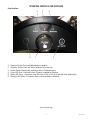
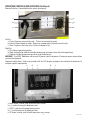
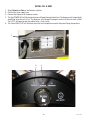
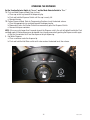
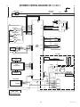
1
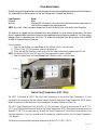
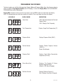
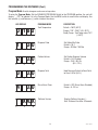
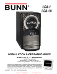
LCR-1
LCA-1
INSTALLATION & OPERATING GUIDE
BUNN-O-MATIC CORPORATION
POST OFFICE BOX 3227
SPRINGFIELD, ILLINOIS 62708-3227
PHONE: (217) 529-6601 FAX: (217) 529-6644
To ensure you have the latest revision of the Operating Manual, or to view the Illustrated Parts
Catalog, Programming Manual, or Service Manual, please visit the Bunn-O-Matic website, at
www.bunn.com. This is absolutely FREE, and the quickest way to obtain the latest catalog and
manual updates. For Technical Service, contact Bunn-O-Matic Corporation at 1-800-286-6070.
44806.0001A
08/11 ©2011 Bunn-O-Matic Corporation
BUNN-O-MATIC COMMERCIAL PRODUCT WARRANTY
Bunn-O-Matic Corp. (“BUNN”) warrants equipment manufactured by it as follows:
1) All equipment other than as specified below: 2 years parts and 1 year labor.
2) Electronic circuit and/or control boards: parts and labor for 3 years.
3) Compressors on refrigeration equipment: 5 years parts and 1 year labor.
4) Grinding burrs on coffee grinding equipment to grind coffee to meet original factory screen sieve analysis:
parts and labor for 3 years or 30,000 pounds of coffee, whichever comes first.
These warranty periods run from the date of installation BUNN warrants that the equipment manufactured by
it will be commercially free of defects in material and workmanship existing at the time of manufacture and
appearing within the applicable warranty period. This warranty does not apply to any equipment, component or
part that was not manufactured by BUNN or that, in BUNN’s judgment, has been affected by misuse, neglect,
alteration, improper installation or operation, improper maintenance or repair, damage or casualty. This warranty is
conditioned on the Buyer 1) giving BUNN prompt notice of any claim to be made under this warranty by telephone
at (217) 529-6601 or by writing to Post Office Box 3227, Springfield, Illinois 62708-3227; 2) if requested by
BUNN, shipping the defective equipment prepaid to an authorized BUNN service location; and 3) receiving prior
authorization from BUNN that the defective equipment is under warranty.
THE FOREGOING WARRANTY IS EXCLUSIVE AND IS IN LIEU OF ANY OTHER WARRANTY, WRITTEN OR
ORAL, EXPRESS OR IMPLIED, INCLUDING, BUT NOT LIMITED TO, ANY IMPLIED WARRANTY OF EITHER
MERCHANTABILITY OR FITNESS FOR A PARTICULAR PURPOSE. The agents, dealers or employees of BUNN
are not authorized to make modifications to this warranty or to make additional warranties that are binding on
BUNN. Accordingly, statements by such individuals, whether oral or written, do not constitute warranties and
should not be relied upon.
If BUNN determines in its sole discretion that the equipment does not conform to the warranty, BUNN, at its
exclusive option while the equipment is under warranty, shall either 1) provide at no charge replacement parts
and/or labor (during the applicable parts and labor warranty periods specified above) to repair the defective
components, provided that this repair is done by a BUNN Authorized Service Representative; or 2) shall replace
the equipment or refund the purchase price for the equipment.
THE BUYER’S REMEDY AGAINST BUNN FOR THE BREACH OF ANY OBLIGATION ARISING OUT OF THE SALE OF
THIS EQUIPMENT, WHETHER DERIVED FROM WARRANTY OR OTHERWISE, SHALL BE LIMITED, AT BUNN’S
SOLE OPTION AS SPECIFIED HEREIN, TO REPAIR, REPLACEMENT OR REFUND.
In no event shall BUNN be liable for any other damage or loss, including, but not limited to, lost profits, lost sales,
loss of use of equipment, claims of Buyer’s customers, cost of capital, cost of down time, cost of substitute
equipment, facilities or services, or any other special, incidental or consequential damages.
392, AutoPOD, AXIOM, BrewLOGIC, BrewMETER, Brew Better Not Bitter, BrewWISE, BrewWIZARD, BUNN Espress, BUNN
Family Gourmet, BUNN Gourmet, BUNN Pour-O-Matic, BUNN, BUNN with the stylized red line, BUNNlink, Bunn-OMatic,
Bunn-O-Matic, BUNNserve, BUNNSERVE with the stylized wrench design, Cool Froth, DBC, Dr. Brew stylized Dr. design,
Dual, Easy Pour, EasyClear, EasyGard, FlavorGard, Gourmet Ice, Gourmet Juice, High Intensity, iMIX, Infusion Series,
Intellisteam, My Café, PowerLogic, Quality Beverage Equipment Worldwide, Respect Earth, Respect Earth with the stylized leaf and coffee cherry design, Safety-Fresh, savemycoffee.com, Scale-Pro, Silver Series, Single, Smart Funnel, Smart
Hopper, SmartWAVE, Soft Heat, SplashGard, The Mark of Quality in Beverage Equipment Worldwide, ThermoFresh, Titan,
A Partner You Can Count On, Air Brew, Air Infusion, Beverage Bar Creator, Beverage Profit Calculator, Brew better, not
bitter., BUNNSource, Coffee At Its Best, Cyclonic Heating System, Digital Brewer Control, Nothing Brews Like a BUNN,
Pouring Profits, Signature Series, Tea At Its Best, Phase Brew, The Horizontal Red Line, trifecta, Ultra, Velocity Brew are
either trademarks or registered trademarks of Bunn-O-Matic Corporation.
2
44806.1 050511
CONTENTS
Warranty..................................................................................................................................................2
User Notices............................................................................................................................................4
Introduction.............................................................................................................................................5
Electrical Requirements...........................................................................................................................5
Plumbing Requirements..........................................................................................................................5
Initial Set-up............................................................................................................................................6
Locating the Dispenser............................................................................................................................6
Electrical Hook-up....................................................................................................................................6
Plumbing Hook-up...................................................................................................................................6
Operating Controls & Interface................................................................................................................7
Installing Pump Tubing............................................................................................................................9
Priming the Concentrate Lines.................................................................................................................9
Initial Fill & Heat.....................................................................................................................................10
Rinse Alarm Feature...............................................................................................................................11
Programming the Dispenser..................................................................................................................12
Operating the Dispenser.........................................................................................................................14
Cleaning & Preventive Maintenance.......................................................................................................15
Replacing the Pump Tubing...................................................................................................................16
Replacing the Air Filter...........................................................................................................................16
Replacing the Water Filter......................................................................................................................16
Calibrating the Dispenser.......................................................................................................................17
Troubleshooting Guide...........................................................................................................................19
Calibration of the Concentrate Pumps....................................................................................................21
Dispenser Flow Rate Calibration............................................................................................................21
Draining the Hot Water..........................................................................................................................22
Schematic Wiring Diagrams...................................................................................................................23
3
44806.1 081211
USER NOTICES
Carefully read and follow all notices on the equipment and in this manual. They were written for your protection. All notices are to be kept in good condition. Replace any unreadable or damaged labels.
As directed in the International Plumbing Code of the
International Code Council and the Food Code
Manual of the Food and Drug Administration (FDA),
this equipment must be installed with adequate
backflow prevention to comply with federal, state
and local codes. For models installed outside the
U.S.A., you must comply with the applicable Plumbing /Sanitation Code for your area.
00656.0001
00986.0002
Risk Of Electrical Shock.
Date: 04/22/10
Do not operate
unit with this
panel removed.
Disconnect power before
servicing unit.
27442-0000
Artwork for P/N: 00656.0001
A
Artwork Rev:
Moving
Parts.
Drawn: REF
27442.0000
CHARGE
Type R134A, Amount 5 oz (141.7 gm)
Design Pressures:
High 269 psi (18.5 bar) (1.8 MPa)
Low 90 psi (6.2 bar) (0.62 MPa)
37881.0000
33461.0005
11646.0002
REMINDER!
CLEAN AIR FILTER
WEEKLY
RECORDATORIO!
LIMPIAR EL FILTRO DE
AIRE SEMANALMENTE
00824.0002
40054.0003
4
44806.1 081211
INTRODUCTION
The BUNN LCA-1 dispenser is design to hold up to 1/2 gal (2 l) of ambient - shelf stable liquid coffee concentrate. The BUNN LCR-1 also holds up to 1/2 gal (2 l) of refrigerated liquid coffee concentrate. Both dispensers
are designed to operate when ambient temperatures are from 32°F (0°C) minimum to 95°F (35°C) maximum.
Always follow the Concentrate Manufacturer’s Storage and Shelf Life recommendations.
ELECTRICAL REQUIREMENTS
Refer to the Data Plate on the dispenser, and local/national electrical codes to determine circuit requirements.
WARNING - If the power cord is ever damaged, it must be replaced by the manufacturer or its service agent with
a special cord available from the manufacturer or its service agent in order to avoid a hazard.
The LCA-1 & LCR-1 are supplied with a 120-volt / 15 Amp cord set and require a 2-wire, grounded, individual
branch circuit rated for 120 volts AC, 15 amp, single phase, 60Hz. The mating connector must be a NEMA 5-15R.
The LCA-1C & LCR-1C are supplied with a 120-volt / 20 Amp cord set and require a 2-wire, grounded, individual
branch circuit rated for 120 volts AC, 20 amp, single phase, 60Hz. The mating connector must be a NEMA 5-20R.
PLUMBING REQUIREMENTS
The dispenser may be connected to a cold or hot water system (140°F Max.) with operating pressure between
20 and 90 psi (138 and 620 kPa) from a 3/8” or larger supply line. A shut-off valve should be installed in the
line before the dispenser. Install a regulator in the line when pressure is greater than 90 psi (620 kPa) to reduce
it to 50 psi (345 kPa). The water inlet fitting is 1/4” flare. The dispensers set up to deliver to 37.0 ml/sec (1.25
Oz./sec.) and require a water supply source that can deliver a minimum of 1.0 gpm (3.8 lpm) at the inlet fitting.
NOTE: Bunn-O-Matic recommends 1/4” tubing from the 3/8” water supply line. At least 18 inches of FDA
approved flexible beverage tubing, such as reinforced braided polyethylene or silicone, before the dispenser will
facilitate movement to clean the counter top. Bunn-O-Matic does not recommend the use of a saddle valve to
install the dispenser. The size and shape of the hole made in the supply line by this type of device may restrict
water flow.
This equipment must be installed to comply with the International Plumbing Code of the International
Code Council and the Food Code Manual of the Food and Drug Administration (FDA). For models installed
outside the U.S.A., you must comply with the applicable Plumbing/Sanitation Code for your area.
NOTE - Water pipe connections and fixtures directly connected to a potable water supply shall be sized, installed
and maintained in accordance with federal, state and local codes.
BUNN recommends the use of our Easy Clear® Water Quality Systems to assure perfect taste.
Filter Kits - Easy Clear EQHP-10L w/Scale Inhibitor (Bunn-O-Matic part no. 39000.0001)
or
Easy Clear EQHP-10 (Bunn-O-Matic part no. 39000.0004)
5
44806.1 081211
INITIAL SET-UP
NOTE: The LCA-1 weighs approximately 40 lbs. (18 kg) and the LCR-1 weighs approximately 55 lbs. (25 kg),
when empty.
If necessary, use more than one person when lifting or moving the dispenser.
1. Cut the plastic bands and remove the top box and other packing.
2. Locate and remove the Adapter Tube Kit, Graphic Kit, Drip Tray & Literature Pkg from the packaging and set
aside.
3. Set dispenser on the counter where it is to be used. CAUTION: DO NOT LIFT ON THE DOOR.
4. Install the drip tray assembly between the front legs. The magnets will hold the tray in place.
5. Install the Graphic decal in the door.
LOCATING THE DISPENSER
Additional clearance is required on both sides and behind the dispenser to allow for proper air flow and cooling.
The LCA-1 requires a minimum space of 16.6” wide x 17.8” tall x 23.0” deep (to allow for the drip tray, water
and electrical connections). The LCR-1 requires a minimum space of 17.1” wide x 17.8” tall x 26.0” deep (to
allow for the drip tray, water and electrical connections). In addition, allow enough clearance on the left-hand
side to allow the door to open freely.
NOTE: In high ambient location where the air temperature around the dispenser could exceed 95°F (35°C), additional clearance is required on both sides and behind the dispenser to allow for proper air flow and cooling.
For these higher temperature locations, the total space required for the LCA-1 is 16.6” wide x 17.8” tall x 23.0”
deep, and 17.1” wide x 17.8” tall x 26.0” deep for the LCR-1.
PLUMBING HOOK-UP
1. Flush the water line to remove any debris or foreign material.
2. Remove the shipping cap from the inlet fitting on the back of the
dispenser and securely attach the water line to the fitting supplied.
3. Turn on the water supply and check for leaks.
ELECTRICAL HOOK-UP
CAUTION: Improper electrical installation will damage electronic components.
Refer to Data Plate on the dispenser, and local/national electrical codes to determine circuit requirements.
1. An electrician must provide electrical service as specified in conformance with all local, state and federal
electrical codes.
2. Using a voltmeter, check the voltage and color-coding of each conductor at the electrical source.
3. Connect the dispenser to the power source.
4. If plumbing is to be hooked up later, be sure the dispenser is disconnected from the power source. If plumbing
has been hooked up, the dispenser is ready for Initial Fill & Heat.
6
44806.1 081211
OPERATING CONTROLS AND INTERFACE
User Interface:
5
3
1.
2.
3.
4.
5.
6.
4
6
1
2
Dispense Switch: Push and Hold to dispense product.
Hot Water Switch: Push and Hold to dispense hot water only.
Portion Switch: Momentarily pushed to select a Portion dispense.
Power LED: Red - illuminates when AC power is applied to dispenser.
Ready LED: Green - illuminates when the water is with in 10 F of the desired water temperature.
Warning LED: Yellow - illuminates when an error condition is detected.
(Continued Next Page)
7
44806.1 081211
OPERATING CONTROLS AND INTERFACE (Continued)
Selector Switches: (Located behind the splash guard panel)
a
a
b
b
c
c
Left Sw:
a. Prime: Dispenses concentrates only – Primes the concentrate pump.
b. Normal: Normal dispense mode - Dispenses mixed product (concentrate and water).
c. Rinse: Dispenses hot water only- Flushes the dispense tip.
Right Sw:
a. Run: Normal operating position.
b. Night: Anti-pilfering mode that disables dispensing, but keeps heater and chiller operational.
c. Program: Enables programming and set up of the dispenser.
WARNING - The NIGHT Mode does not remove AC power from the dispenser. Disconnect power source before
servicing the dispenser.
Programming Switches: Used in conjunction with the LED display to program and calibrate the dispenser to
customer specific requirements.
e
d
c
b
a
a. Down Arrow: used to scroll to the next menu screen.
b. (+): used to increase the displayed value.
c. (EXIT): used to exit the programming menu.
d. (-): used to decrease the displayed value.
e. UP Arrow: used to scroll to back to previous menu screen.
8
44806.1 081211
INSTALLING PUMP TUBING
INSTALLING THE PUMP TUBING
1. Remove the BIB and product shelf to access the pump assembly.
2. Loosen thumbscrew (Fig 1) to remove the cover plate and set it aside.
3. Depress tension screw and remove it from notch in the pump body to release the tension on the pump band.
(Fig 1)
4. Pull the pump tube from around pump rotor.(Fig 1)
5. Inspect pump bands for signs of wear and replace if necessary.
6. Apply lubricant (BUNN-O-MATIC part no. M2548.1000) to the middle section of the new pump tubing.(Fig 2)
7. Wrap the new pump tubing around the rotor, making sure the elbow is snug against the inlet of the pump.(Fig3)
8. Depress tension screw and insert it in notch in the pump body, reapplying spring tension on the pump band.
(Fig 3)
9. Connect the pump tubing the port on the SST dispense tube. (Fig 3).
10.Replace the cover plate and tighten thumbscrew.
11.Route the BIB Adapter tube through the notch in the product shelf and re-install the shelf. (Fig 4)
12.Reconnect the BIB Adapter to the product BIB. (Fig 5)
Note: Replacement Tube Kits can be purchased from BUNN-O-MATIC. Order part no. 44713.1000
FIG 1
FIG 2
FIG 3
FIG 4
FIG 5
Remove Cover
Release Tension
Remove Tubing
Lubricate
New Tube
Install Tubing
Reset Tension
Replace Cover
Route Tubing
Replace Shelf
Connect BIB
Completed
Installation
PRIMING THE CONCENTRATE LINE
1. Open the dispenser door.
2.Select Prime and Run on the Selector switches.
3. Close the dispenser door.
4. Place a container under the dispense tip.
5. Activate the dispenser until concentrate flows from the dispense nozzle, (5 to 10 seconds).
6. Open the dispenser door, select Normal on the Selector switch.
Note: Concentrate may continue to drip out of dispense tip. The user may wish to Rinse the dispenser to clean
out the remaining concentrate.
2
6
9
44806.1 081211
INITIAL FILL & HEAT
1.Select Normal and Run on the Selector switches.
2. Confirm the water supply is on.
3. Connect the dispenser to the power source.
4. The Red POWER LED will illuminate and water will begin flowing into the tank. The dispenser will automatically
stop filling when the tank is full. The dispenser will not begin heating the water until after the tank is filled.
The LCR-1 will begin to cool the cabinet after a 3 min. delay.
5. The Green READY LED will illuminate when the tank temperature reaches the preset Ready temperature.
1
5
4
10
44806.1 081211
Rinse Alarm Feature
Periodic rinsing of the dispense tip is essential for proper maintenance and optimum performance of the dispenser.
The automated Rinse Alarm feature has two levels of operation, Disabled and Warning.
Level Selected
Alarm
DisabledNone
Warning
Warning LED will come on 4 hrs prior to the selected time interval and remain on
until the Rinse procedure has been performed.
NOTE: Alarm Only - Does not prevent dispensing. To clear the Rinse Alarm, refer to the Rinse Procedure.
The dispenser is shipped with the automated Rinse Alarm disabled. It is up to the user to determine if the Rinse
Alarm is needed and the time interval, based on their application and maintenance procedures. The time interval
between Rinses is adjustable from 8 to 24 hrs. To enable the automated Rinse Alarm feature, refer to RINSE
ALARM in Programming the Dispenser.
Rinse Procedure:
1. Open the cabinet door and select Rinse on the Selector switch – close the door.
2. Place a 2 Liter (1/2 Gal) container under the dispense tip.
3. Press and hold the Dispenser switch until water flow stops automatically, approximately 20 sec.
NOTE: The Warning LED will turn OFF, when the Rinse procedure has been satisfied.
4. Open the cabinet door and select Normal on the Selector switch – close the door.
4
1
Cabinet Target Temperature (LCR-1 Only)
The LCR-1 is designed to “HOLD” Non-shelf stable concentrate at the desired Target Temperature. It is not
designed to chill concentrate that has not been stored at or below the desired Target Temperature. NOTE: Always
follow the concentrate Manufacturer’s recommendations for proper Storage and Shelf Life.
The LCR-1 Target Temperature is pre-set to 40° F (4° C) at the factory and can be adjusted from 35° to 75° F (2 24° C), see Calibrating the Dispenser to adjust the Target Temperature. NOTE: When operating temperatures are
above 85° F (30° C), it may be necessary to lower the Target Temperature 5° to maintain the concentrate at the
desired temperature. If ice starts to build up on the evaporator inside the cabinet, raise the Target Temperature
a few degrees.
The Maximum Recommended Operating Temperature for the LCR-1 is 95° F (35° C).
11
44806.1 081211
PROGRAMMING THE DISPENSER
Two basic modes are available to the operator: Display Mode and Program Mode. Open the dispenser door to
access the digital Programming Switches with LED display. To enter the Display Mode, Set the RUN/NIGHT/
PROGRAM Switch to the RUN position.
Display Mode: Used to view the current set-up values. Use the MENU switch to scroll to the next display.
NOTE: The display blanks out after two minutes of inactivity. Press any button to activate the display.
LED DISPLAY DISPLAY MODE DESCRIPTION
180
MENU
(-)
(-)
MENU
(-)
MENU
(-)
3
MENU
(-)
(-)
Portion Volume
Displays Portion Dispense Volume
(XX.X Oz.).
Set to 0.0 to Disable.
Dispense Total
Displays Total Coffee Concentrate
Dispensed (XX.X Gal)
Rinse Alarm (Hrs)
Displays The Number Of Hours
Between Required Rinses.
(Default = OFF, Alarm Disabled)
Software Version
Displays Software Version # Exits To Home View After 3 Seconds.
12
44806.1 081211
(+)
XX.X
MENU
Displays Dispense Ratio (XXX:1)
(+)
4 OF F
MENU
Dispense Ratio
(+)
0. 0
(-)
Displays Target Tank Temperature (F°)
(+)
0. 0
2
Tank Temperature
(+)
30
1
LCR-1 Alternates between the Tank and
Cabinet Temp.
LCA-1 Displays Tank Temp only.
(+)
0 180
MENU
Home View
(+)
PROGRAMMING THE DISPENSER (Cont.)
Program Mode: Used to change or enter new set-up values.
To enter the Program Mode, Set the RUN/NIGHT/PROGRAM Switch to the PROGRAM position, the unit will
display “__PPP” to indicate it is in the Program Mode. Use the MENU switch to scroll to the next display. Use
the Increase (+) and Decrease (-) switch to adjust the values.
LED DISPLAY
PROGRAM MODE DESCRIPTION
0 180
MENU
(-)
MENU
(-)
2
MENU
3
MENU
4
MENU
(-)
Set Portion Dispense Volume
Default = 0.0, Disabled
Range = 16.0 / 40.0 Oz.
(0.5 / 1.2 L)
Dispense Total
Hold Decrease Switch to Reset Total
to Zero. 0.0 Gal (0.0 L)
Rinse Alarm Timer
Default = OFF (Rinse Alarm Disabled)
Range = 8 - 24 hrs
Software Version
Displays Software Version # Exits To Home View After 3 Seconds.
13
44806.1 081211
(+)
XX.X
MENU
Portion Volume
(+)
0. 0
(-)
Set Coffee Mix Ratio
Default = 30:1
Range = 20 Max / 100 Min
(+)
0. 0
(-)
Dispense Ratio
(+)
0. 0
(-)
Default = 180°F (82°C)
Range = 120° - 200°F (49 - 93°C)
Ready Temp = Tank Temp minus 10°F
(~5.5°C)
(+)
30
1
Tank Temperature
(+)
OPERATING THE DISPENSER
Set the Function Selector Switch to “Normal” and the Mode Selector Switch to “Run.”
1A.Push and Hold Dispense Mode (Cup at a time).
a. Place cup on the tray beneath the dispensing tip.
b. Push and hold the Dispense Switch until the cup is nearly full.
c. Remove the cup.
1B.Portion Dispense Mode. Refer to Programming Functions to set the desired volume.
a. Place the appropriate size container beneath the dispensing tip.
b. Momentarily press the Portion Switch then momentarily press the Dispense Switch.
c. Remove the cup or container.
NOTE: If the user waits longer than 5 seconds to push the Dispense switch, the unit will default back to the Push
and Hold mode. A Portion dispense can be aborted at any time by momentarily pushing the Dispense switch again.
d. Wait for the container to fill and the dispenser to quit dispensing.
3. Hot Water Dispense
a. Place a container under the dispense tip.
b. Push and hold the Hot Water switch until water reaches the desired level, then release.
14
44806.1 081211
GENERAL CLEANING AND SANITIZING PROCEDURES
Note: The BUNN® LCA-1 & LCR-1 dispensers incorporates a “user selectable” rinse reminder feature, which
displays warning LED on the front panel when it is time to rinse. See Programming Functions to activate this
feature.
DAILY RINSING
1. Open dispenser door and select Rinse and Run on the Function switches.
2. Close dispenser door and place a container under dispense nozzle area.
3. Press the dispense switch until the water runs clear or has no concentrate coloring in it, (10 to 20 sec.).
4. Open dispenser door, set the Function switch back to Normal.
Note: To clear the “Rinse” warning, you must hold the dispense switch until flow stops automatically (~20 sec).
The “Rinse” LED will turn off when the Rinse time has been satisfied.
DAILY PARTS WASHING
1. Remove and wash drip tray and drip tray cover in a mild detergent solution. Rinse thoroughly.
2. Wipe splash panel, dispense nozzles, door, and cabinet with a clean damp cloth.
WEEKLY SANITIZING
1. Open dispenser door and select Prime and Run on the Function switches.
2. Remove the connector from the product box and disassemble or prop open the internal valve to allow free
flow of product through the connector. Note: Cutting the mating fittings from an empty bag makes an excellent “free flowing” connector for this purpose.
3. Place the connector into a 1/2 gallon (2 liter) container of warm soapy tap water 140F (60C).
4. Place a container under the dispense tip and activate the dispense switch until clean soapy water is dispensed
from the dispense tip.
5. Repeat steps 3 and 4 with warm tap water 140F (60C) to rinse the soapy water from the pump tubing. Continue activating the dispense switch until water is clear, and no soapy water is being dispensed.
6. Prepare 1 gal. (3.8 L) of sanitizing solution by dissolving 0.4 Oz (11.4 grams) of Kay-5® Sanitizer into 1 gal.
(3.8 L) of 120 F (48.9 C) water to ensure 100 ppm of available chlorine.
7. Repeat steps 3 and 4 with the sanitizing solution. Once the sanitizing solution is visible, continue to dispense
for 1 minute.
8. Allow the sanitizer solution to sit for 5 minutes in the tubing.
9. After soaking for 5 minutes, activate the Dispense Switch a second time for 2 minutes.
10.Repeat step 3 and 4 with warm tap water to flush the sanitizing solution out of the pump tubing.
11.Reattach bag connector to product box and select Normal and Run on the Function switches
12.Actuate the dispense switch until concentrate/water mixture appears. Continue to dispense at least 12 oz.
(350 ml) of concentrate/water mixture and discard.
Wipe internal and external surfaces with a clean, damp cloth.
15
44806.1 081211
PREVENTIVE MAINTENANCE
Bunn-O-Matic Corporation recommends that preventive maintenance be performed at regular intervals. Maintenance
should be performed by a qualified service technician. For Technical Service, contact Bunn-O-Matic® Corporation at
1-800-286-6070.
NOTE: Replacement parts or service caused by failure to perform required maintenance is not covered by warranty.
Replace pump hoses every 6-Months or as needed.
®
REPLACING THE PUMP TUBING
The pumps and tubing used in the dispenser are designed to give maximum performance and long life. However, the
tubes are a wear item and must be replaced periodically. How long the tubes last is dependent on usage and properties of
the concentrate. Excessive wear will reduce the output of the pumps resulting in a weak mixed beverage. Bunn-O-Matic
recommends replacing the Pump Tubing a minimum of once every 6 months or sooner if warranted. Refer to the Tube
Replacement Instruction inside the Cabinet door.
REPLACING THE PUMP TUBING
Note: Rinse tubing with warm water (steps 1 - 4 of the Weekly Sanitizing Instructions) prior to removing to avoid spills.
1. Remove the BIB and product shelf to access the pump assembly.
2. Loosen thumbscrew (Fig 1) to remove the cover plate and set it aside.
3. Depress tension screw and remove it from notch in the pump body to release the tension on the pump band. (Fig 1)
4. Pull the pump tube from around pump rotor. (Fig 1)
5. Inspect pump bands for signs of wear and replace if necessary.
6. Apply lubricant (BUNN-O-MATIC part no. M2548.1000) to the middle section of the new pump tubing. (Fig 2)
7. Wrap the new pump tubing around the rotor, making sure the elbow is snug against the inlet of the pump.(Fig3)
8.Depress tension screw and insert it in notch in the pump body, reapplying spring tension on the pump band. (Fig 3)
9. Connect the pump tubing the port on the SST dispense tube. (Fig 3).
10.Replace the cover plate and tighten thumbscrew.
11.Route the BIB Adapter tube through the notch in the product shelf and re-install the shelf. (Fig 4)
12.Reconnect the BIB Adapter to the product BIB. (Fig 5)
Note: Replacement Tube Kits can be purchased from BUNN-O-MATIC. Order part no. 44713.1000
FIG 1
FIG 2
FIG 3
FIG 4
FIG 5
Remove Cover
Release Tension
Remove Tubing
Lubricate
New Tube
Install Tubing
Reset Tension
Replace Cover
Route Tubing
Replace Shelf
Connect BIB
Completed
Installation
CLEANING THE AIR FILTER: LCR-1Kiss
Only
cut
A dirty or clogged air filter will reduce the performance of the refrigeration system
and could cause the compressor to overheat? Weekly cleaning of the air filter is
Run
Prime
recommended. Remove the metal Air Filter from the
Left side
panel and wash in
Night in clean water and
Normal Rinse
warm soapy water, until all grease and dirt is removed.
dry thoroughly before putting back in the LCR-1. Rinse
Prgm
REPLACING THE WATER FILTER:
Refer to the instructions supplied with the water filter kit for the recommended intervals and procedure for
44710.0000A 03/11 © 2011 Bunn-O-Matic Corporation
replacing the filter cartridge.
Die cut
16
44806.1 081211
CALIBRATING THE DISPENSER
NOTE: The LCA/LCR-1 is calibrated at the factory and does not normally need to be re-calibrated. Open the
dispenser door to access the digital Programming Switches with LED display. To enter the Calibration Mode, Set
the RUN/NIGHT/PROGRAM Switch to the PROGRAM position and then hold both Up and Down Arrow switches
until “1 r u n” appears of the display, (approx 15 sec).
LED DISPLAY CALIBRATION MODE DESCRIPTION
1 r un
MENU
(-)
1
MENU
(-)
(-)
3
MENU
(-)
(-)
Water Flow Rate
Enter mL collected from the 20 sec.
test above.
Default = 760
Range = 780 - 820 mLiters
Cabinet Temperature
LCR-1 Only Used to set the Target
Cabinet Temperature
Default = 40°F (4°C)
Range = 35°F - 75°F (2° - 24°C)
English or Metric Mode
Used to select the desired units.
Default = English
S.I. for Metric
Error Code Memory
Display cycles through the last (3)
Error Codes.
Erase by holding the Decrease (-)
switches for 10 sec.
Currently have to hold (+) & (-)
(+)
5 E_ _
MENU
Set PRIME-NORMAL-RINSE switch
to RINSE position. Place Graduated
Cylinder under dispense tip. Press and
hold Dispense Switch until pump stops
(20 sec) Refer to Calibration Procedure.
(+)
4 Eng
MENU
Water Flow Rate
(+)
40
(-)
Enter mL collected from the 20 sec.
test above.
Default = 22
Range = 18 - 26mL
(+)
2 760
MENU
Pump Cal. #
(+)
2 r un
MENU
Set PRIME-NORMAL-RINSE switch
to PRIME position. Place Graduated
Cylinder under dispense tip. Press and
hold Dispense Switch until pump stops
(20 sec) Refer to Calibration Procedure.
(+)
22
(-)
Pump Cal. Procedure
(+)
17
44806.1 081211
CALIBRATING THE DISPENSER (Cont.)
LED DISPLAY CALIBRATION MODE DESCRIPTION
6 - - MENU
(-)
(-)
(-)
Pump “OFF” Delay
Delays the Pump turn off after a
dispense.
Default = 200
Range = 1 - 999 mSec.
Software Version
Displays current Software Version # Exits To Home View After 3 Seconds.
18
44806.1 081211
(+)
- XX.X
MENU
Resets all set up values to the Factory
Default setting.
Reset by holding the Decrease (-)
switches for 10 sec.
Currently have to hold (+) & (-)
(+)
_ 20 0
MENU
Reset Factory Defaults
(+)
TROUBLESHOOTING GUIDE
Error Codes
When an error has occurred, the Warning LED will be flashing. Open the door to view the LED Display and
record the Error # shown on the display. Refer to the list of Error Codes below to identify the problem. The
troubleshooting guide is provided to suggest probable causes and remedies for most problems. If the problem
remains after exhausting the troubleshooting steps, contact the Bunn-O-Matic Technical Service Department.
LED DISPLAY ERROR DESCRIPTION/TROUBLESHOOTING
E _01
MENU
(-)
(-)
(-)
(-)
(-)
Fill Time Too Long
Fill Valve ON continuous for more than
15 minutes.
Water turned OFF. Refill Valve
disconnected or faulty.
Tank Temp Sensor Error
Sensor reading Out Of Range (High
or Low).
Check Sensor wires for shorts, loose
or open connections.
Dispense Time Too Long
Dispense or Hot Water switch has been
ON for more than 2 Min.
Check: Dispense switches for proper
operation or damage. Door harness
for shorts.
(+)
E _05
MENU
Tank Heater ON continuous for more
than 1 hour.
Check heater wires for loose or open
connections.
(+)
E _04
MENU
Heating Time Too Long
(+)
E _03
MENU
Motor or RPM Sensor failure. Check
motor and RPM Sensor wires for shorts, loose or open
connections.
(+)
E _02
MENU
Pump Error
(+)
19
44806.1 081211
TROUBLESHOOTING GUIDE (Cont.)
Error Codes (Continued)
The Follow errors codes apply to the LCR-1 only.
LED DISPLAY ERROR DESCRIPTION/TROUBLESHOOTING
E _06
MENU
(-)
(-)
Sensor reading Out Of Range (High or
Low).
Check Sensor wires for shorts or open
connections.
Cooling Time Too Long
Cabinet Sensor has not reached the
set point in 4 hours.
Check: Air Filter plugged or blocked.
Cabinet door left open or faulty seal.
Wiring for shorts or open connections.
Evaporator iced up.
Ambient operating temperature is
greater than 95°F (35°).
(+)
E _07
MENU
Cool Temp Sensor Failed
(+)
20
44806.1 081211
CALIBRATION OF THE CONCENTRATE PUMP & DISPENSER FLOW RATE
The factory set default values for the Pump & Dispenser Flow Rates are very accurate and typically do not need
to be field calibrated. However, if the mix ratio accuracy is ever in question, this procedure can be used to recalibrate the unit in the field.
Equipment Required:
50 ml graduated cylinder, with 1 ml graduations.
1000 ml graduated container.
NOTE: You can calibrate either the Concentrate Pump or the Dispenser Flow Rate independently. Simply scroll
through the menu screen to the desired section and perform only those steps.
Calibrating the Concentrate Pumps.
1. Open the door of the dispenser and select PROGRAM on the Selector Switch. The display should show PPP.
2. Depress and Hold both Up & Down arrows switch for approximately 15 sec. The unit will display “1 run”
when it has entered the Calibration Mode.
3. Select PRIME on the Selector Switch.
4. Place a container under the dispense tip and depress the dispense switch until a steady stream of concentrate
comes out the tip (5 to 10 seconds).
5. Stop priming and allow the tip to stop dripping. Discard the concentrate collected.
6. Place a 50 ml graduated cylinder under the Dispense Tip.
7. Press & Hold the dispense switch. The dispenser will display a 20 second count down timer and then shut
the pump OFF automatically. You can abort the calibration and stop the pump by releasing the switch.
8. Keep the graduated cylinder under dispense tip until all the concentrate has dripped out.
9. Measure the volume of concentrate collected in the graduated cylinder.
The acceptable range for the volume of concentrate collected is 16 - 26 ml
10.If the amount collected is not within the acceptable range, repeat STEPS 6 – 9.
11.If the amount collected is still not within range, replace the pump tubing with a new Tube Kit, (refer to the
Tube Replacement Instructions) and restart this procedure.
12.When satisfied with the volume of concentrate collected, press the Down Arrow switch. The current Calibration volume “1 XX” will be displayed.
13.Use the (-) or (+) keys to adjust the number displayed to the amount measured in STEP 9.
(Continued Next Page)
21
44806.1 081211
CALIBRATION OF THE CONCENTRATE PUMP & DISPENSER FLOW RATE
(Continued)
Calibrating the Dispenser Flow Rates.
1. Select RINSE on the Selector Switch.
2. Press the Down Arrow switch to display the Flow Rate calibration menu “2 run”
3. Place a container under dispense tip and depress the dispense switch until a steady stream of water comes
out the tip (5 to 10 seconds).
4. Stop dispensing and allow the tip to stop dripping. Discard the water collected
5. Place a 1000 ml graduated container under dispense tip.
6. Press & Hold the dispense switch. The dispenser will display a 20 second count down timer and then stop
dispensing automatically. You can abort the calibration and stop the dispense by releasing the switch.
7. Keep the graduated container under dispense tip until all the water stops dripping.
8. Measure the volume of water collected in the graduated container.
The acceptable range for the volume of water collected is 700 to 820 ml
9. If the amount of water collected is not within the acceptable range, empty the graduated container and repeat
STEPS 5 – 8.
10.If the amount collected is still not within range, inspect the dispense valves, tubing and mix chamber for lime,
kinks or other obstructions.
11.When satisfied with the volume of water collected, press the Down Arrow switch. The current Water Calibration volume “2 .XX0” will be displayed.
12.Use the (-) or (+) keys to adjust number displayed to the amount measured in STEP 8 in Liters, (not ml).
DRAINING THE HOT WATER TANK
CAUTION: The dispenser must be disconnected from the power source throughout these steps.
1. Disconnect the dispenser from the power source.
2. Shut off and disconnect the incoming water supply.
3. Remove the rear access panel.
4. Close the tube clamp on the hose from the inlet valve to the tank.
5. Remove the hose from the inlet fitting and direct it into a 150 Oz (4.5L) or larger container.
6. Open the tube clamp. Continue draining tank until ALL of the water is out. Be careful when draining the water
as it may be very hot.
7. Reconnect the tube to the inlet valve.
8. Leave the tube clamp open and replace the rear access panel.
Note: The dispenser must be refilled using the Initial Fill & Heat steps before reconnecting the power source.
22
44806.1 081211
SCHEMATIC WIRING DIAGRAM LCR-1 / LCA-1
L1
N
GRN
TANK HEATER
LIMIT THERM.
120 V 1425 W
BLK-16
WHT-16
1
BLK-16
COM
N.O.
BLK
WHT
ORG
WHT/VIO
ORG
WHT/RED
BRN/WHT
HOT WATER
WHT
SOL
WHT/RED
WHT
WHT
WHT
BLK
PRODUCT VALVE
WHT
SOL
WHT/VIO
J4-1
J10-1
J10-4
J4-5
WHT
PNK
BLK
GRN
BLK
WHT
PNK
GRN
TANK
t°
J4-10
J8-1
INLET VALVE
WHT
SOL
BRN/WHT
J8-5
WHI/YEL
WHI/BLK
YEL
PRIME
NORMAL
RINSE
PUMP
RPM SENSOR
PUMP
M
RED
BLK
GRN
1
WHT
PNK
RED/BLK
ORG
RED
BLK
PNK
ORG
RED/BLK
J7-1
MAIN
CONTROL
BOARD
J8-10
GRY
BLU
WHT/GRY
PROGRAM
NIGHT
RUN
J8-14
J7-5
RED
BLK
MEMBRANE SWITCH
DOOR
J9-4
WHT/VIO
BLK
WHI
YEL
BLU
GRN
ORG
DOOR
CONTROL BOARD
BLK
BLK
J9-6
J1-1
+ RED
BLK
-
WHT/GRN
BRN
J1-5
J1-6
BLU/BLK
WHI
MEMBRANE SWITCH
PROGRAM
J11-1
J2-1
J2-4
J11-5
CONDENSER
BRN
RELAY
0
1 COIL
2
4 CONTACT
6
BLU/BLK 8 CONTACT
YEL
WHI
BLK
BLK
120 VOLTS AC
2 WIRE + GRD
SINGLE PHASE, 60 HZ
CONDENSER FAN
YEL
ORG
WHI
WHI
GRN
WHT/GRN
BLK
WHI
SECONDARY
COMPRESSOR
WHI
TRANSFORMER
PRIMARY
GRN
WHI
TAN
WHI/ORG
WHI
BLK
TAN
WHI/ORG
t°
EVAPORATOR
VIO
1
J9-1
EVAPORATOR FAN
LCR-1 ONLY
44869.0000B 08/11 © 2011 Bunn-O-Matic Corporation
23
44806.1 081211