1
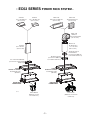
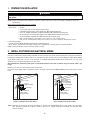
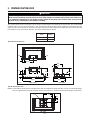
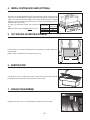
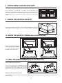
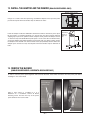
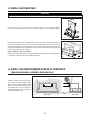
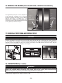
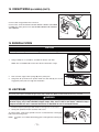
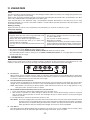
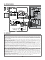
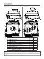
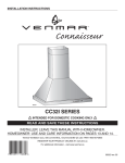
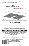
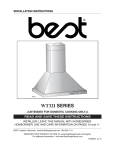
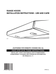
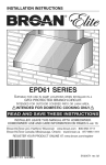
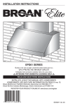
INSTALLATION INSTRUCTIONS
HB0091
EC62 SERIES
!
INTENDED FOR DOMESTIC COOKING ONLY
!
READ AND SAVE THESE INSTRUCTIONS
INSTALLER: LEAVE THIS MANUAL WITH HOMEOWNER.
HOMEOWNER: USE AND CARE INFORMATION ON PAGE 12.
Broan-NuTone Canada Inc.; Mississauga, Ontario www.broan.ca
877-896-1119
www.broan.ca
REGISTER YOUR PRODUCT ON LINE AT: www.broan.ca
SV08970 rev. 05
!
WARNING
!
WARNING
TO REDUCE THE RISK OF FIRE, ELECTRIC
SHOCK OR INJURY TO PERSONS, OBSERVE
THE FOLLOWING:
TO REDUCE THE RISK OF INJURY TO PERSONS
IN THE EVENT OF A RANGE TOP GREASE
FIRE, OBSERVE THE FOLLOWING*:
1.
1.
2.
3.
4.
5.
6.
7.
8.
9.
10.
Use this unit only in the manner intended by the
manufacturer. If you have questions, contact the
manufacturer at the address or telephone number
listed in the warranty.
Before servicing or cleaning unit, switch power off
at service panel and lock service disconnecting
means to prevent power from being switched on
accidentally. When the service disconnecting
means cannot be locked, securely fasten a prominent
warning device, such as a tag, to the service panel.
Installation work and electrical wiring must be done
by qualified personnel in accordance with all
applicable codes and standards, including fire-rated
construction codes and standards.
Sufficient air is needed for proper combustion and
exhausting of gases through the flue (chimney) of
fuel burning equipment to prevent backdrafting.
Follow the heating equipment manufacturer’s
guidelines and safety standards such as those
published by the National Fire Protection
Association (NFPA), and the American Society for
Heating, Refrigeration and Air Conditioning
Engineers (ASHRAE), and the local code authorities.
When cutting or drilling into wall or ceiling, do not
damage electrical wiring and other hidden utilities.
Ducted fans must always be vented to the
outdoors.
To reduce the risk of fire or electric shock, do not
use this unit with any additional solid-state speed
control device.
To reduce the risk of fire, use only metal ductwork.
This unit must be grounded.
When applicable local regulations comprise more
restrictive
installation
and/or
certification
requirements, the aforementioned requirements
prevail on those of this document and the installer
agrees to conform to these at his own expenses.
SMOTHER FLAMES with a close-fitting lid,
cookie sheet or metal tray, then turn off the
burner. BE CAREFUL TO PREVENT BURNS. IF
THE FLAMES DO NOT GO OUT IMMEDIATELY,
EVACUATE AND CALL THE FIRE DEPARTMENT.
2.
NEVER PICK UP A FLAMING PAN – You may
be burned.
3.
DO NOT USE WATER, including wet dishcloths or
towels – This could cause a violent steam explosion.
4.
Use an extinguisher ONLY if:
A. You own a Class ABC extinguisher and
you know how to operate it.
B. The fire is small and contained in the area
where it started.
C. The fire department has been called.
D. You can fight the fire with your back to an exit.
*Based on “Kitchen Fire Safety Tips” published by NFPA.
CAUTION
1.
2.
3.
4.
5.
TO REDUCE THE RISK OF A RANGE TOP
GREASE FIRE:
6.
a)
Never leave surface units unattended at high settings.
Boilovers cause smoking and greasy spillovers that
may ignite. Heat oils slowly on low or medium settings.
7.
b)
Always turn hood ON when cooking at high heat or
when flambeing food (i.e. Crêpes Suzette, Cherries
Jubilee, Peppercorn Beef Flambé).
8.
Clean ventilating fans frequently. Grease should not
be allowed to accumulate on fan, filters or in exhaust
ducts.
9.
c)
d)
Use proper pan size. Always use cookware appropriate
for the size of the surface element.
10.
-2-
For indoor use only.
For general ventilating use only. Do not use to exhaust
hazardous or explosive materials and vapors.
To avoid motor bearing damage and noisy and/or
unbalanced impellers, keep drywall spray,
construction dust, etc. off power unit.
Your power pack motor has a thermal overload
which will automatically shut off the motor if it
becomes overheated. The motor will restart when it
cools down. If the motor continues to shut off and
restart, have the power pack serviced.
The minimum hood distance above cooktop must
not be less than 24”. A maximum of 30” above
cooktop is highly recommended for best capture of
cooking impurities. For a gas range, the bottom of
the hood MUST NOT BE LESS than 30” above
cooktop.
Two installers are recommended because of the
large size and weight of this unit.
To reduce the risk of fire and to properly exhaust
air, be sure to duct air outside – Do not exhaust air
into spaces within walls or ceiling or into attics,
crawl space or garage.
Because of the high exhausting capacity of this
unit, you should make sure enough air is entering
the house to replace exhausted air by opening a
window close to or in the kitchen.
To reduce the risk of fire and electrical shock, the
Broan Elite EC62 Series models must be installed
only with their own built-in blower(s). Other blowers
cannot be substituted.
Please read specification label on product for
further information and requirements.
- EC62 SERIES
STANDARD
3¼” X 10” ROOF CAP
(NOT INCLUDED)
POWER PACK SYSTEM -
STANDARD
3¼” X 10” WALL CAP
(NOT INCLUDED)
MODEL 437
HIGH CAPACITY ROOF CAP
(NOT INCLUDED)
MODEL 441
10” ROUND WALL CAP
(NOT INCLUDED)
MODEL 418
10” ROUND
ADJUSTABLE ELBOW
(NOT INCLUDED)
MODEL 410
10” ROUND DUCT
— 2 FT. SECTIONS
(NOT INCLUDED)
STANDARD
3¼” X 10” DUCT
(NOT INCLUDED)
10” ROUND VERTICAL
IN-LINE DAMPER
(SUPPLIED WITH 1000
10” ROUND ADAPTER
(SUPPLIED WITH 1000 CFM
DUAL BLOWER POWER PACK)
3¼” X 10” ADAPTER/DAMPER
(SUPPLIED WITH SINGLE BLOWER
POWER PACK)
L6230SS,
L6236SS OR L6242SS
CUSTOM HOOD LINER
(OPTIONAL)
L6230SS,
L6236SS OR L6242SS
CUSTOM HOOD LINER
(OPTIONAL)
EC622301SS
POWER PACK
EC621306SS
POWER PACK
HL0126
SINGLE BLOWER
(600 CFM, SUPPLIED
WITH POWER PACK)
(1000
-3-
CFM
DUAL BLOWER POWER PACK)
DUAL BLOWER
CFM, SUPPLIED WITH
POWER PACK)
1. PREPARE THE INSTALLATION
!
WARNING
When performing installation, servicing or cleaning the unit, it is recommended to wear safety glasses
and gloves.
NOTE: Before proceeding to the installation, check the contents of the box. If items are missing or damaged, contact the
manufacturer.
Make sure that the following items are included:
- Power Pack
- Accessories: • 2 Filters
• 2 Filter knobs with screws, taped inside the hood
• 2 Shielded halogen lamps (120 V, 50 W max., MR16 with GU10 base)
• 3¼” x 10” adapter and damper (supplied with 600 CFM single blower power pack)
• 10” round in-line vertical damper (supplied with 1000 CFM dual blower power pack)
• 10” round adapter (supplied with 1000 CFM dual blower power pack)
• Bag of parts including: 1 wire clamp, 2 wire connectors, 4 no. 8 x 3/8” screws,
9 no. 8 x 1/2” chrome plated screws, 10 no. 8-32 x 1/4” screws. If need be, discard extra screws.
Parts sold separately:
- Custom hood liner Model L6230SS, L6236SS or L6242SS (optional)
- Ducts, elbows, wall and roof caps. Refer to page 3 for a complete list of venting options and model numbers.
NOTE: During installation, protect countertop and/or cooktop.
2. INSTALL DUCTWORK AND ELECTRICAL WIRING
Plan where and how the ductwork will be installed. Access to the top of the power pack is preferred for connection of ductwork.
Install proper-sized ductwork, elbows and roof or wall cap for the type of power pack you are installing. If installing EC621306SS
single blower power pack, use 3¼” x 10” ductwork. If installing EC622301SS double blower power pack, use 10” round
ductwork. Use 2” metal foil duct tape to seal duct joints.
We recommend to install the power pack at a minimum distance of 24” from an electric range and at 30” from a gas
range.
Distances over 30” are at the installer and users discretion.
Run 3-wire power supply cable to installation location. Its length should extend at least 4 feet below the bottom of the custom
hood.
Roof cap
Roof cap
3¼” x 10” duct
3¼” x 10”
adapter & damper
Wall
cap
Wall
cap
Power pack
10” round duct
10” in-line
vertical damper
10” round elbow
10” round adapter
Power pack
24” minimum above
cooking surface
(30” for gas range)
24” minimum above
cooking surface
(30” for gas range)
HH0117A
HH0116A
MODEL EC621306SS
(SINGLE BLOWER) TYPICAL DUCTWORK
(DUAL
MODEL EC622301SS
DUCTWORK
BLOWER) TYPICAL
NOTE: Although the horizontal discharge installation is feasible with EC621306SS power pack model, this installation
type should be performed in specific situation only since it requires particular knowledge and technical skills
from the installers.
-4-
3. PREPARE CUSTOM HOOD
!
WARNING
When building a custom hood, always follow all applicable construction codes and standards. The custom
hood must be positively secured to wall studs or other wooden framework behind the drywall. Make sure
it is capable of supporting its own weight and the weight of the power pack. Failure to do so may cause
personal injury or damage to countertop or cooktop.
The custom hood must be constructed to fit the shape and total weight of the EC62 power pack model. The recommended
minimum thickness for the custom hood base is 5/8”. If an optional custom hood liner will be installed, we recommend the sides
and front of the custom hood to be 3/4” thick. If the optional custom hood liner will not be installed, the custom hood sides and
front thickness are at the installer’s discretion. See chart and illustration for details.
POWER PACK
TYPES
TOTAL
WEIGHT
SINGLE BLOWER
DUAL BLOWER
33
45
LB
LB
SINGLE BLOWER POWER PACK
TOP VIEW
7/8”
5/8”
1¾”
13 5/16”
10½”
5/8”
3 ³/16”
1¾”
9¾”
10 15/16”
10 1/8”
3 ³/16”
2 15/16”
26 5/8”
28
HK0104A
13¼”
11/16”
1/8”
14¾”
BACK VIEW
SIDE VIEW
DUAL BLOWER POWER PACK
NOTE: The dual blower model has the same dimensions than the single blower model, but does not have a horizontal discharge.
Refer to single blower power pack illustration for back and side views, and discard horizontal discharge measurements.
13 5/16”
ø10”
1¾”
7/8”
5¼”
HK0114A
TOP VIEW
-5-
4. INSTALL CUSTOM HOOD LINER (OPTIONAL)
The liners are specially designed to protect the exterior base of the custom hood. To
order, refer to the table below to find the right liner model number according to the
width of the custom hood nominal width. To view specific model information, including
depths for each liner models, visit www.broan.ca or contact Technical Support (phone
number listed on front cover).
To install, see instruction packed with custom hood
liner.
NOTE: The liner must be installed before the insert.
LINER MODEL
L6230SSS
L6230SSS
L6230SSS
CUSTOM HOOD
NOMINAL WIDTH
30”
36”
42”
HA0067A
5. CUT THE HOLE IN CUSTOM HOOD BASE
If it is not done yet, cut a hole in the bottom of the custom hood, using the dimensions
shown at right.
13³/8”
NOTE: Keep in mind that the unit exterior flange is 3/4’’.
26¾”
HD0340A
6. REMOVE FILTER
Rest the power pack on a table. Remove tape on filters. Lift filters from power pack by
pushing them towards the back and rotate, then set filters aside.
HD0366
7. UNPLUG THE BLOWER(S)
Unplug the blower(s) (one or two, depending on model) from the front panel.
HE01105
-6-
8. REMOVE WIRING COVER AND FRONT PANEL
Using a Robertson or a Phillips no. 2 screwdriver, remove both wiring cover
retaining screws (A). Detach it from the power pack and set aside with its screws.
Then, remove both sides screws (B) retaining the front panel to the power pack.
Carefully detach the front panel from the power pack and set aside with its
screws.
A
B
HD0365
9. REMOVE THE ELECTRICAL KNOCKOUT
C
From inside the power pack, punch out the electrical knockout hole on top left
side (C) OR on back left side (D). Install the wire clamp (included in parts bag).
D
HR0030
10. REMOVE THE KNOCK-OUT OPENING (SINGLE BLOWER MODEL ONLY)
Remove the knockout opening on
top (vertical discharge installation)
or on back (horizontal discharge
installation) of the power pack.
1
2
HR0037
11. INSTALL THE ADAPTER/DAMPER (SINGLE BLOWER MODEL ONLY)
VERTICAL DISCHARGE INSTALLATION
Using 2 no. 8 x 3/8’’ screws provided in parts bag,
secure the adapter/damper to the top of the power
pack. Remove tape from damper flap. Seal the
adapter to the power pack using metal foil duct tape.
HO0137
HORIZONTAL DISCHARGE INSTALLATION
The adapter/damper will be installed on the back of the power pack once the power pack will be mounted in the custom hood.
Refer to step 15.
-7-
12. INSTALL THE ADAPTER AND THE DAMPER (DUAL BLOWER MODEL ONLY)
MOUNTING SCREW LOCATION
Using 2 no. 8 x 3/8’’ screws from parts bag, assemble the adapter on the top of the power
pack. Seal all joints with metal foil duct tape to eliminate air leaks.
HJ0035
Install 10” damper inside the VERTICAL ductwork that will be attached to power pack.
Do not install in a horizontal ductwork or it will not open and close properly. Remove
shipping tape if present. To optimize airflow and quiet sound, position the damper at least
17” above the top of the double blower power pack; or as far as the duct run will allow. Also,
ensure the damper hinge will be parallel to power pack sides (see figure at right). Secure
the damper to the duct with 3 no. 8 sheet metal screws (not provided). Check to make sure
damper opens and closes freely. Seal all joints with metal foil duct tape to eliminate air
leaks.
DAMPER
HINGE
PARALLEL TO
POWER PACK
SIDES
17” min.
HJ0036A
13. REMOVE THE BLOWER
(SINGLE BLOWER MODEL, HORIZONTAL DISCHARGE ONLY)
In order to ease the power pack alignment with horizontal ductwork, disassemble the blower from the power pack before
installing it in the custom hood.
LEFT SIDE MOUNTING
SCREW LOCATION
RIGHT SIDE MOUNTING
SCREW LOCATION
Using a 5/16” socket, or a Phillips no. 2 or a
Robertson no. 2 screwdriver, remove all blower
mounting screws from the inner top of the power
pack. Set blower and screws aside.
HD0368
HD0369
-8-
14. INSTALL THE POWER PACK
CAUTION
Take care not to kink ducting or pinch electrical cable when installing the power pack.
CLASPING
SPRINGS
Lift the power pack in custom hood until the bottom of the clasping springs
(2 per side) rests on the top of the custom hood base (grey zone in illustration at right).
HD0370
From inside the power pack, using provided no. 8-10 x 1/2” screws, mount the power pack
to the custom hood base. To do so, raise the front until its flange rests on the outer side of
the custom hood base and use 2 screws to secure in place. Do the same for the back, then
complete the installation with 2 additional screws on the front and back. See figure at right
for mounting screws specific locations.
VERTICAL EXHAUST INSTALLATION
ONLY
Make sure the adapter/damper enters the ducting and the damper opens freely. Wherever
it is possible, seal connections with metal foil duct tape.
HH0126
15. INSTALL THE ADAPTER/DAMPER ON BACK OF POWER PACK
(SINGLE BLOWER MODEL, HORIZONTAL DISCHARGE ONLY)
From the outside of the wall, using two
no. 8 x 3/8’’ screws provided in parts
bag, secure the adapter/damper to the
back of the power pack. Remove tape
from damper flap. Connect ducting to
the adapter/damper and seal the joint
using metal foil duct tape.
WALL
HH0127A
BACK VIEW
-9-
SIDE VIEW
16. REINSTALL THE BLOWER (SINGLE BLOWER MODEL, HORIZONTAL DISCHARGE ONLY)
The single blower power pack is factory shipped for a
vertical discharge installation. For a horizontal
discharge installation, the blower must be flipped.
Using a 5/16” socket, or a Phillips no. 2 or a
Robertson no. 2 screwdriver, secure the blower to the
inner back of the power pack with all blower mounting
screws (previously removed in step 13).
RIGHT SIDE
MOUNTING SCREW
LOCATION
LEFT SIDE MOUNTING
SCREW LOCATION
HD0371
HD0372
17. REINSTALL FRONT PANEL AND WIRING COVER
CAUTION
Take care not to pinch wiring when reinstalling the front panel and the wiring cover.
Carefully reassemble the front panel to the power pack by aligning the tabs with their corresponding slot. Using a Robertson
no. 2 or a Phillips no. 2 screwdriver, secure the front panel to the power pack using its both retaining screws (A) previously
removed in step 8. Reassemble the wiring cover using its both retaining screws (B) previously removed in step 8. Plug the
motor(s) (one or two, depending on models) to the front panel.
B
A
HD0365
HE01105
HO0138
18. CONNECT WIRING (ALL MODELS)
!
WARNING
Risk of electric shock. Electrical wiring must be done by qualified personnel in accordance with all applicable
codes and standards. Before connecting wires, switch power off at service panel and lock service
disconnecting means to prevent power from being switched on accidentally.
Position the power pack below the installed custom hood. Insert the house wiring cable through the wire clamp previously
installed in step 9. Tighten the wire clamp to secure the cable.
- 10 -
18. CONNECT WIRING (ALL MODELS) (CONT’D)
A
Connect cable using provided wire connectors.
Connect wires as follow: BLACK to BLACK, WHITE to WHITE and GREEN
or BARE wire under ground screw (A). DO NOT FORGET TO CONNECT
THE GROUND.
HE0059
19. REINSTALL FILTERS
CAUTION
Remove protective plastic film covering filters before installing them.
1.
Using a Phillips no. 2 screwdriver, assemble the knob to each filter.
NOTE: The screw MUST BE on filter tabs side. See illustration at right.
HO0139
2.
Rest rear filters edge on filter springs (B) in the power pack.
3.
Using knob, tilt up the filters into position. Make sure filter tabs (C) are securely
engaged in power pack front edge after installation.
B
HD0373
C
20. LIGHT BULBS
This power pack requires shielded halogen lamps (120 V, 50 W max., MR16 or PAR16 with GU10 base), included.
!
WARNING
Do not touch lamps during or soon after operation. Burns may occur. In order to prevent the risk of
personal injury, only install shielded halogen lamps. Also, never install a cool beam, a dichroïc lamp, a
lamp not suitable for use in recessed luminaires or identified for use in enclosed fixtures.
1.
Install the lamps by placing the bulb leads into their grooves in the socket.
2.
Gently push upwards and turn clockwise until secure.
1
To remove lamps, gently push upwards and turn counterclockwise to disengage
bulb leads from their grooves.
NOTE: If need be, use a rubber dishwashing glove to add grip when removing the
bulb.
HO0090
- 11 -
2
21. USE AND CARE
Filters
The filters should be cleaned frequently. Use a warm detergent solution. Wash more often if your cooking style generates more
grease — like frying foods or wok cooking.
Remove filters by pushing it towards the back of power pack and rotating filter downward. Filters are dishwasher safe. Allow
filters to dry completely before reinstalling them in the power pack.
Clean all-metal filters in the dishwasher using a non-phosphate detergent. Discoloration of the filters may occur if using
phosphate detergent or as a result of local water conditions — but this will not affect filter performance. This discoloration is not
covered by the warranty.
Blower(s) Cleaning
Remove the filters in order to access the blower(s). Vacuum blower(s) to clean. Do not immerse in water.
Power Pack Cleaning
Stainless steel cleaning:
Do:
• Regularly wash with clean cloth or rag soaked with warm
water and mild soap or liquid dish detergent.
• Always clean in the direction of original polish lines.
• Always rinse well with clear water (2 or 3 times) after
cleaning. Wipe dry completely.
• You may also use a specialized household stainless steel
cleaner.
Don’t:
• Use any steel or stainless steel wool or any other scrapers
to remove stubborn dirt.
• Use any harsh or abrasive cleansers.
• Allow dirt to accumulate.
• Let plaster dust or any other construction residues reach the
power pack During construction/renovation, cover the power
pack to make sure no dust sticks to stainless steel surface.
Avoid when choosing a detergent:
- Any cleaners that contain bleach will attack stainless steel.
- Any products containing: chloride, fluoride, iodide, bromide will deteriorate surfaces rapidly.
- Any combustible products used for cleaning such as acetone, alcohol, ether, benzol, etc., are highly explosive and should
never be used close to a range.
22. OPERATION
Always turn your power pack on before you begin cooking to establish an air flow in the kitchen. Let the blower run for a few
minutes to clear the air after you turn off the range. This will help keep the whole kitchen cleaner and brighter.
HC0023
A
B
C
D
A.
DELAY SWITCH:
When a blower speed is selected, press this switch to activate the delay function. The corresponding blower speed switch
will flash to indicate this function is activated. The blower will continue to operate for 5 minutes and will stop automatically.
To cancel the delay function, press the delay switch once again.
B.
START/STOP/SPEED SELECTION SWITCHES:
Press the switch corresponding to the desired blower speed (from 1 for low speed to 4 for high speed). The chosen switch
will light. To turn off the blower, press once more on the corresponding blower speed switch; the switch light will shut off.
NOTE: When blower is off, pressing on blower speed 1 switch will cause the blower to start on high speed for a very
short lapse of time, and then resume on speed 1.
C.
MASTER OFF/FILTER MAINTENANCE/HEAT SENTRY (TRIPLE FUNCTION SWITCH):
i. To turn off the blower(s) and the light simultaneously, press this switch once.
ii. After 25 hours of operation, this switch will light to indicate the filters and the blower wheel(s) need to be cleaned in
order to maintain efficient operation of the unit. The switch light will stay on until the function is reset by pressing this
switch for 3 seconds.
iii. The light indicator is used for the Heat Sentry function as well.
HEAT SENTRY: The hood is equipped with a protective device that activates when excessive heat is detected inside the hood
and when it is set on speed 4. This device takes control of the blower and deactivates speed 4 for a 10-minute
period and sets it on speed 3. During the Heat Sentry activation, only speed 3 can be used; the Heat Sentry
button (C) will flash while the speed 3 button will light. The hood can also be turned OFF.
D.
LIGHT SWITCH:
This switch allows three different lighting levels according to your needs. Press once for nightlight, twice for normal or three
times to obtain full intensity. To shut off the lights without turning off the blower, press once more.
- 12 -
120 VAC
23. WIRING DIAGRAM
BLK
LINE
WHT
NEUTRAL
GROUND
Q1
TRANSFORMER
LOGIC
LAMP
WHT
RED 9.5 V
LAMP
YEL
BLK
YEL
BLOWER MOTOR
K4
10 VAC
K1 NC
3
ASSEMBLY
K3
REF
2
YEL
K2 NC
K3 NC
WHT
J2
BLU
BLU
WHT
M
ELECTRONIC
120 V LINE
1
WHT
BRN
A1
K2
J1
WHT
GRY
K1
BLK
YEL
COLOR CODE
BLK
BLACK
BLU
BLUE
BRN
BROWN
GRY
GREY
ORG
ORANGE
RED
RED
WHT
WHITE
YEL
YELLOW
BLK
WHT
BLU
WHT
ORG
ORG
WHT
K3 NO
K4 NO
2
ORG
BLK
RED
K2 NO
1
WHT
BLK
K1 NO
3
BLK
4
5
BLU
OPTIONAL SECOND
BLOWER MOTOR
HE0132A
M
WHT
ORG
WHT
BLK
BLK
24. WARRANTY
ONE YEAR LIMITED WARRANTY FOR BROAN ELITE PRODUCTS
Broan-NuTone Canada (Broan-NuTone) warrants to the original consumer purchaser of Broan Elite products that such products will be free
from defects in materials or workmanship for a period of one year from the date of original purchase. THERE ARE NO OTHER WARRANTIES,
EXPRESS OR IMPLIED, INCLUDING, BUT NOT LIMITED TO, IMPLIED WARRANTIES OR MERCHANTABILITY OR FITNESS FOR A
PARTICULAR PURPOSE.
During this one-year period, Broan-NuTone will, at its option, repair or replace, without charge, any product or part which is found to be
defective under normal use and service.
THIS WARRANTY DOES NOT EXTEND TO FLUORESCENT LAMP STARTERS, TUBES, HALOGEN AND INCANDESCENT BULBS, FUSE,
FILTERS, DUCTS, ROOF CAPS, WALL CAPS AND OTHER ACCESSORIES FOR DUCTING. This warranty does not cover (a) normal
maintenance and service or (b) any products or parts which have been subject to misuse, negligence, accident, improper maintenance or
repair (other than by Broan-NuTone), faulty installation or installation contrary to recommended installation instructions.
Warranty service is to be completed by an authorized Service Center designated by Broan-NuTone. Where applicable, in-home service will
be made available only in areas where a contracted service provider offers service. If in-home service is not available, the product will be
repaired or replaced, at Broan-NuTone’s discretion, by the nearest authorized service provider. The unit removal and reinstallation works are
under the customer responsibility, and Broan-NuTone cannot be charged for them.
The duration of any implied warranty is limited to the one-year period as specified for the express warranty. Some provinces do not allow
limitation on how long an implied warranty lasts, so the above limitation may not apply to you.
BROAN-NUTONE’S OBLIGATION TO REPAIR OR REPLACE, AT BROAN-NUTONE’S OPTION, SHALL BE THE PURCHASER’S SOLE
AND EXCLUSIVE REMEDY UNDER THIS WARRANTY. BROAN-NUTONE SHALL NOT BE LIABLE FOR INCIDENTAL, CONSEQUENTIAL
OR SPECIAL DAMAGES ARISING OUT OF OR IN CONNECTION WITH PRODUCT USE OR PERFORMANCE. Some provinces do not
allow the exclusion or limitation of incidental or consequential damages, so the above limitation or exclusion may not apply to you.
This warranty gives you specific legal rights, and you may also have other rights, which vary from province to another. This warranty
supersedes all prior warranties.
To qualify for warranty service, you must (a) notify Broan-NuTone at the address or telephone number stated below, (b) give the model
number and part identification and (c) describe the nature of any defect in the product or part. At the time of requesting warranty service, you
must present evidence of the original purchase date.
Broan-NuTone Canada Inc., 1140 Tristar Drive, Mississauga, ON L5T 1H9 www.broan.ca 1-877-896-1119
- 13 -
25.SERVICE PARTS
EC621306SS
EC622301SS
1
1
11
11
10
2
3
3
4
4
9
5
6
10
2
5
8
6
7
9
8
7
HL0169
KEY
NO.
PART
NO.
2
3
4
5
6
7
8
9
10
11
*
SV13296
SV08541
SV09226
SV05917
SV05921
SV09435
SV09434
SV18428
SV08967
SV08582
SV09022
SV06750
SV08970
*
SV08545
1
*NOT
DESCRIPTION
ADAPTER/DAMPER 3¼” X 10”
ADAPTER 10” ROUND
ELECTRONIC CONTROL WITH CHROMED BUTTONS AND BLUE LEDS
SOCKET
SOCKET HOLDER
LIGHT TRIM
SHIELDED HALOGEN BULB (120 V, 50 W, GU-10)
THIN BAFFLE FILTER
FILTER KNOBS (INCLUDING SCREWS) (QTY. 2)
INTERNAL BLOWER
TRANSFORMER
BROAN ELITE LOGO
INSTALLATION GUIDE
PARTS BAG: 2 WIRE CONNECTORS, 1 WIRE CLAMP,
4 SCREWS NO. 8 X 3/8”, 9 CHROMED PLATED SCREWS NO. 8-10 X 1/2”,
10 MECHANICAL SCREWS NO. 8-32 X 1/4”
QTY. (POWER PACK MODEL)
EC621306SS EC622301SS
1
1
1
1
2
2
2
2
2
2
2
2
2
2
1 PAIR
1 PAIR
1
2
1
1
1
1
1
1
1
1
SHOWN.
REPLACEMENT PARTS
AND
REPAIRS
In order to ensure your unit remains in good working condition, you must use Broan-NuTone genuine replacement parts only. Broan-NuTone
genuine replacement parts are specially designed for each unit and are manufactured to comply with all the applicable certification standards and
maintain a high standard of safety. Any third party replacement part used may cause serious damage and drastically reduce the performance
level of your unit, which will result in premature failing. Broan-NuTone recommends to contact a certified service depot for all replacement
parts and repairs.
- 14 -