1
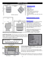
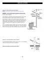
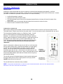
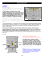
OWNER’S MANUAL WARNING: IF YOUR APPLIANCE IS NOT PROPERLY INSTALLED A HOUSE FIRE MAY RESULT. FOR YOUR SAFETY, FOLLOW THE INSTALLATION DIRECTIONS. CONTACT LOCAL BUILDING OR FIRE OFFICIALS ABOUT RESTRICTIONS AND INSTALLATION INSPECTION REQUIREMENTS IN YOUR AREA. PLEASE READ THIS ENTIRE HEATER. FAILURE TO FOLLOW EVEN DEATH. SAVE THESE INSTRUCTIONS. MANUAL BEFORE INSTALLATION AND USE OF THIS MULTI-FUEL BURNING ROOM THESE INSTRUCTIONS COULD RESULT IN PROPERTY DAMAGE, BODILY INJURY, OR Manufactured By: National Steelcrafters of Texas - Arlington, TX BRECKWELL HEARTH PRODUCTS 11/09 TABLE OF CONTENTS INTRODUCTION ....................................................................................................................................................... i SAFETY PRECAUTIONS ............................................................................................................................................ ii INSTALLATION ........................................................................................................................................................ 1 Specifications ...................................................................................................................................................... 1 Approved Installations .......................................................................................................................................... 1 Preparation ......................................................................................................................................................... 1 Floor Protection ................................................................................................................................................... 2 Venting ............................................................................................................................................................... 2 Combustion Air Supply ......................................................................................................................................... 3 Electrical Installation ............................................................................................................................................ 3 Special Mobile Home Requirements ....................................................................................................................... 4 Examples of Proper Installation ............................................................................................................................. 4 OPERATION ............................................................................................................................................................ 7 Proper Fuel ......................................................................................................................................................... 7 First Time Use Pre-Start Check .............................................................................................................................. 8 Lighting Directions ............................................................................................................................................... 8 Control Panel....................................................................................................................................................... 9 General Operation ............................................................................................................................................... 9 Heat Level Light Indicators ................................................................................................................................. 12 Optional Thermostat .......................................................................................................................................... 13 Control Panel Reset............................................................................................................................................ 14 SET THE CONTROL BOARD: ................................................................................................................................... 14 MAINTENANCE ...................................................................................................................................................... 15 Ash Disposal...................................................................................................................................................... 15 Ash Removal ..................................................................................................................................................... 15 Vacuum Use ...................................................................................................................................................... 15 Cleaning ........................................................................................................................................................... 16 Recommended Maintenance Schedule ................................................................................................................. 17 Removal and Replacement of Broken Door Glass .................................................................................................. 17 TROUBLESHOOTING GUIDE ................................................................................................................................... 18 Stove Shuts Off and the Second Light Flashes ...................................................................................................... 18 Stove Shuts Off and the Third Light Flashes ......................................................................................................... 19 Smoke Smell Coming Back Into The Home ........................................................................................................... 20 Convection Blower Shuts Off and Comes Back On ................................................................................................. 20 Stove Will Not Feed Fuel, But Auger Light Does Come On ..................................................................................... 20 Dirty Burn ......................................................................................................................................................... 21 High Limit Switch Keeps Tripping ........................................................................................................................ 22 Digital Circuit Board Timing Rates Stir Motor Timing Rates . ......................................................................................................... 22 . ........................................................................................................... 22 REPLACEMENT PARTS ............................................................................................................................................ 24 INTRODUCTION INTRODUCTION Thank you for purchasing the Breckwell SP 6000 Multi-Fuel Stove. You are now prepared to burn whole shelled corn and wood pellets in the most efficient, convenient way possible. To achieve the safest, most efficient and most enjoyable performance from your stove, you must do three things: 1) install it properly; 2) operate it correctly; and 3) maintain it regularly. The purpose of this manual is to help you do all three. PLEASE READ THIS ENTIRE MANUAL BEFORE INSTALLATION AND USE OF THIS MULTI-FUEL ROOM HEATER. FAILURE TO FOLLOW THESE INSTRUCTIONS COULD RESULT IN PROPERTY DAMAGE, BODILY INJURY OR EVEN DEATH. KEEP THIS MANUAL HANDY FOR FUTURE REFERENCE. This stove has been independently tested to ASTM E1509-04 Standard Specification for Room Heaters, Pellet Fuel Burning Type 1, ULC/ORD 1482-90 Standard for Solid Fuel Room Heaters, and Oregon Administrative Rules for Mobile Homes (814-23-900 through 814-23-909) and Installation as a Stove Heater. CHECK WITH YOUR LOCAL AUTHORITIES (SUCH AS THE MUNICIPAL BUILDING DEPARTMENT, FIRE DEPARTMENT, BUILDING IF SO, BE SURE TO FOLLOW ALL LOCAL GUIDELINES REGARDING THIS PRODUCT AND PROCUREMENT OF THE PERMIT PRIOR TO OPERATION OF THIS UNIT. INSPECTOR, ETC.,) TO DETERMINE IF A PERMIT IS NEEDED. This pellet stove, when installed, must be electrically grounded in accordance with local codes, or in the absence of local codes, with the National Electrical Code, ANSI/NFPA 70. The stove will be properly grounded when plugged into a standard three prong wall outlet that has been properly grounded. This appliance is designed and tested specifically for use only with whole shelled corn or pelletized wood. It is approved for residential installation according to the current national and local building codes as a freestanding room heater. It is also approved for use in a mobile home. The stove is designed for connection to an outside combustion air source. The stove will not operate without a power source for the blower systems and fuel feed systems. The unit is NOT designed to operate using natural draft. This unit is designed for burning wood pellets or corn only. It cannot be operated with any type of coal (see the PROPER FUEL section). This stove is designed to provide the optimum proportions of fuel and air to the fire in order to burn free of smoke and soot. Any blockage of the air supply to or from the stove will seriously degrade its performance and will be evidenced by a smoking exhaust and a sooting window. For best operation the ash content of the wood pellet fuel should be less than 3% and the calorific value approximately 8200 BTU/LB. Avoid high ash content fuels because this will rapidly fill up the burn pot and eventually cut off the combustion air supply. CORN MUST CONTAIN LESS THAN 12% MOISTURE CONTENT. Ideally, the corn will be as low of a moisture content as possible for best performance. 12% moisture is the highest that should ever be used. Wet corn will rapidly deteriorate stove components, reduce the efficiency and cleanliness of the burn, and void all warranties. Commercial and industrial installations of Breckwell SP 6000 Multi-Fuel Stove should not be used since operational control is often not well managed in these settings. Model: SP 6000 Multi-Fuel Stove Style: Freestanding MAIL YOUR WARRANTY CARD TODAY To receive full warranty coverage, you will need to show evidence of the date you purchased your stove. We suggest that you attach your sales invoice to this page, and fill in the form on the left, so that you will have all the information you need in one place should the need for service or information occur. Serial Number: Purchase Date: Purchased From: i SAFETY PRECAUTIONS SAFETY PRECAUTIONS Do not operate your stove if you smell smoke coming from it. Turn it off, monitor it, and call your dealer. Never try to repair or replace any part of the stove unless instructions are provided. A trained technician should do all other work. Never use gasoline, gasoline-type lantern fuel, kerosene, charcoal lighter fluid, or similar liquids to start or “freshen up” a fire in this stove. Keep all such liquids well away from the stove while in use. Do not throw this manual away. This manual has important operating and maintenance instructions that you will need at a later time. Always follow the instructions in this manual. Read the manual thoroughly. Never block free airflow through the open vents of the stove. Do not place clothing or other flammable items on or near the stove. Keep foreign objects out of the hopper. Be sure that when you add fuel to the hopper, the pellets or corn that you are using is free of foreign material. The viewing door must be closed and latched during normal operation. The stove will not operate during a power outage. If an outage does occur, keep the stove door closed, and open a window if any smoke spills into the room. Adequate vertical vent pipe on the exhaust will prevent smoke from entering the home. Do not operate the stove if the flame becomes dark and sooty or if the burn pot overfills with fuel. Turn the stove off, inspect it, and call your dealer or a qualified, trained technician. Disconnect the power cord before performing any maintenance or repairs on the stove. NOTE: Turning the stove “off” does not disconnect all power from the stove. CAUTION: Hot while in operation. Keep children, clothing, and furniture away. Contact may cause skin burns. Educate all children of the danger of a high temperature stove. Young children should be supervised when they are in the same room as the stove. DO NOT open the viewing door during the start up period. If the stove is installed in a room without air conditioning, or in an area where direct sunlight can shine on the unit, it is possible this can cause the temperature of the stove to rise to operational levels; one of the sensors could then make the stove start on its own. It is recommended that the stove be unplugged when not in use for extended amounts of time (i.e. during the summer months). Do not unplug the stove if you suspect a malfunction. Turn the stove off, inspect it, and call your dealer or qualified, trained technician. Contact your local building officials to obtain a permit and information on any installation restrictions or inspection requirements in your area. Notify your insurance company of this stove as well. The exhaust system must be completely airtight and properly installed. The exhaust vent joints must be sealed with RTV 500°F (260°C) silicone sealant, and with UL-181AP foil tape. This unit must be properly installed to prevent the possibility of a house fire. The instructions must be strictly adhered to. Do not use makeshift methods or compromise in the installation. Allow the stove to cool before carrying out any maintenance or cleaning. Ashes must be disposed in a metal container with a tight lid and placed on a non-combustible surface well away from the home structure. Your stove requires periodic maintenance and cleaning. Failure to maintain your stove may lead to smoke spillage in your home, or even a more dangerous situation. This stove is designed and approved for pelletized wood fuel and corn only. Any other type of fuel burned in this heater will void the warranty and safety listing, and may result in a hazardous condition. This stove must be connected to a standard 120 V., 60 Hz grounded electrical outlet. Do not use an adapter plug or sever the grounding plug. Do not route the electrical cord underneath, in front of, or over the stove. When installed in a mobile home, the stove must be bolted to the floor, have outside air connected (see page 3), and NOT BE INSTALLED IN A BEDROOM (Per H.U.D. requirements). Check with local building officials. The exhaust system should be checked regularly. It is recommended that the exhaust system be inspected once a month, or for every ton of pellets burned. At a minimum, even if burning less than a ton per year, the exhaust should be checked twice a burning season. Breckwell Hearth Products grants no warranty, implied or stated, for the installation or maintenance of your stove, and assumes no responsibility of any consequential damage(s). ii INSTALLATION INSTALLATION Specifications Width: 27 ¼” Height: 35 ½” Depth: 28 ⅝” Weight: 225 Pounds Flue Size: 3” or 4 “ Hopper Capacity: 90 Pounds (Corn) (This will vary depending on fuel) EPA Status: Exempt Maximum BTU Input: 50,000 BTU with whole corn Approved Installations Alcove, Conventional, Mobile Home Preparation Factory packaging must be removed, and some minor assembly work is required prior to installation and use. Access to the rear and sides of the stove will be necessary at some point in time so be sure to leave ample room for access, otherwise, be prepared to move the stove when necessary. Install the ceramic Brick Panel onto the rear combustion wall. THIS IS A REQUIRED COMPONENT. The Brick Panel is fragile, so handle with care at all times. Your stove warranty only covers this item from thermal breakage. Impact damage resulting from dropping or accidental abuse is not covered. AUGER INSTALLATION: Install the auger into the auger tube as shown in Figure 2. The flat face of the auger is toward the front of the stove, and the beveled edge will go into the auger tube. Make sure the auger is all the way to the rear and is engaged or seated properly. STIR ROD & BURN POT INSTALLATION: The Burn Pot must be set into the Burn Pot Holder with the fuel spreader towards the rear of the stove, as shown. Insert the stir rod into the burn pot with the beveled connector toward the left. Align the beveled segments so that the holes on each piece align, and insert the cotter pin. Pressing the Auger Feed button while the stove is off rotates the stir motor shaft. This will assist you in aligning these two pieces. 1 INSTALLATION Floor Protection Freestanding installations require a minimum 33 ¼” wide by 36” long floor protection. The stove must be placed on a continuous (grouted joints) noncombustible material such as ceramic tile, cement board, brick, 3/8” millboard or equivalent, or other approved or listed material suited for floor protection. THE MATERIAL(S) USED MUST HAVE, OR COMBINE TO HAVE, A MINIMUM INSULATIVE RATING OF ‘R1’. NOTE: CERAMIC TILE, OR ANY OTHER TILE, REQUIRES A CONTINUOUS SHEET OF NON-COMBUSTIBLE MATERIAL BENEATH TO PREVENT THE POSSIBILITY OF EMBERS FALLING THROUGH TO THE COMBUSTIBLE FLOOR IF CRACKS OR SEPARATION SHOULD OCCUR IN THE FINISHED SURFACE. THIS INCLUDES FLOOR PROTECTION FOR BUILT-IN RAISED HEARTHS. CHECK LOCAL CODES FOR APPROVED ALTERNATIVES. Clearances are measured from the sides, back and face (door opening) or stove body. DO NOT USE MAKESHIFT MATERIALS OR COMPROMISES IN THE INSTALLATION OF THIS UNIT. Venting The SP 6000 Multi-Fuel is certified for use with listed TYPE L-Vent, 3” or 4” diameter in size. The stove was tested with Simpson Duravent brand. Class “A” chimney is not required. Refer to the instructions provided by the vent manufacturer, especially when passing through a wall, ceiling or roof. This is a pressurized exhaust system. ALL VENT CONNECTOR JOINTS MUST BE SECURED WITH AT LEAST THREE SCREWS AND with 500F (260C) RTV silicone sealant and UL-181-AP foil tape to ensure consistent performance and to avoid smoke spillage. SEALED DO NOT CONNECT THIS UNIT TO A CHIMNEY FLUE SERVING ANOTHER APPLIANCE. DO NOT INSTALL A FLUE DAMPER IN THE EXHAUST VENTING SYSTEM OF THIS UNIT. INSTALL VENT AT CLEARANCES SPECIFIED BY THE VENT MANUFACTURER. Equivalent Vent Length (EVL) The longer the length of your exhaust flue, the more restriction there is in the system. Therefore, a larger diameter pipe should be used. As such, prior to purchasing and installing your unit, you should carefully plan your installation and calculate the equivalent vent length (EVL) of your planned installation. Use the following to calculate your EVL: 90º Elbow or Tee = 5 Feet 45º Elbow = 3 Feet Horizontal Pipe = 1 Foot per actual foot (actual measurement) Vertical Pipe = ½ Foot per actual foot (1/2 of actual measurement) If your EVL is less than 15’ you may use 3” diameter pipe. However, if your EVL is 15’ or greater you must use 4” diameter pipe. If your exhaust configuration has three elbows, or if you have a corner installation going out a sidewall, 4” diameter pipe should be used regardless of your EVL calculation. NOTE: FOR BEST PERFORMANCE LIMIT THE AMOUNT OF HORIZONTAL PIPE AS MUCH AS POSSIBLE. YOU SHOULD NEVER HAVE MORE THAN 5’ OF HORIZONTAL PIPE. NOTE: AT ALTITUDES ABOVE 3,000 FEET, 4” PIPE IS REQUIRED WITH AN EVL OF 7’ OR MORE. 2 INSTALLATION Combustion Air Supply A 2” inside diameter metallic pipe, either flexible or rigid, may be attached to the inlet at the stove’s rear. A rodent guard (minimum ¼” wire mesh)/wind hood must be used at the terminus. All connections must be secured and airtight by either using the appropriately sized hose clamp and/or UL-181-AP foil tape. NOTE: A COMBUSTION AIR SUPPLY IS REQUIRED FOR ALL MOBILE HOME INSTALLATIONS, AND ALSO IN CONVENTIONAL HOME INSTALLATIONS IF THE UNIT IS BEING INSTALLED IN A BASEMENT, SMALL ROOM, OR EXTREMELY WELL INSULATED OR AIRTIGHT HOMES. FOR MOBILE HOME INSTALLATIONS ONLY: For a mobile home installation the stove must be connected to an outside source of combustion air per federal regulations. 2” inside diameter pipe may be used for the first 5 feet of combustion air supply run. From 5 to 10 feet use 2 ¾” inside diameter pipe. NO COMBUSTION AIR SUPPLY MAY EXCEED 10 FEET OF EVL. EVL (Equivalent Vent Length) for combustion air supply is calculated the same as for the venting or exhaust pipe. SOURCES OF OUTSIDE COMBUSTION AIR In fireplaces, outside air can be piped to the stove from the chimney top, fireplace ash clean out door, or a hole drilled through the back of the fireplace. The run of pipe for the combustion air supply should be as short as possible for the best performance. For freestanding installations, this could be a hole in the floor near the stove rear terminating in a ventilated crawl space, or a hole in the wall behind the stove. In tightly insulated homes, a closeable outside air register can be used. WHEN OUTSIDE AIR IS NOT USED If outside air is not used, it is important that the combustion air inlet is not restricted or blocked in any way. Electrical Installation This stove is provided with a 6-foot grounded electrical cord extending from the rear of the stove. We recommend connecting to a good, HIGH QUALITY SURGE PROTECTOR that is plugged into a standard three-prong, 120V, 60 Hz electrical outlet. It is highly recommended that you get a surge protector rated as close to 130 Volts and 10 AMPS as possible. The closer your surge protector is to these ratings, the greater the protection for your stove. Voltage variations or incorrect polarity can lead to serious performance problems, especially related to the control board. The Breckwell electrical system is designed for 120V AC with no more than 5% variation. The polarity of the outlet should also be checked during installation. Most hardware stores carry an inexpensive polarity checker. Breckwell cannot accept responsibility for poor performance or damage due to inadequate voltage or incorrect polarity. If connected to an older, two-prong outlet, a separate ground wire must be run to a proper ground (contact a qualified electrician). Always route the electrical cord so that it will not come in contact with any hot part of the stove. 3 INSTALLATION Special Mobile Home Requirements WARNING: DO NOT INSTALL IN A SLEEPING ROOM. For installation in a mobile home, the outside air connection (fresh air) must be used. The Breckwell SP 6000 Multi-fuel must be grounded to the steel chassis of the home with 8 Ga. copper wire using a serrated or star washer to penetrate paint or protective coating to ensure grounding. The Breckwell SP 6000 Multi-fuel must be securely fastened to the floor of the mobile home through the holes in the side of the pedestal of the stove using 2, ¼” lag bolts that are long enough to go through both a hearth pad, if used, and the floor of the home. NOTE: INSTALLATION OF THIS UNIT INTO A MOBILE HOME MUST BE IN ACCORDANCE WITH THE “MANUFACTURED HOME & SAFETY STANDARD” (HUD), CFR 3280, PART 24. THE STRUCTURAL INTEGRITY OF THE MOBILE HOME FLOOR, WALL AND CEILING/ROOF MUST BE MAINTAINED. Examples of Proper Installation Horizontally Through Wall NOTE: FOLLOW L-VENT CHIMNEY MANUFACTURER’S INSTRUCTIONS. 1. Position stove, adhering to clearances shown in Figure 1. 2. Locate position of hole in wall directly behind stove exhaust vent (refer to figure 3). 3. Always maintain 3” clearance from combustible materials. 4. Install L-Vent wall thimble per L-Vent manufacturer’s instructions. 5. Attach enough piping to penetrate and extend beyond exterior walls. Attach an elbow or cleanout Tee and take the pipe vertical. A MINIMUM OF 5-FOOT VERTICAL RUN OF PIPE IS REQUIRED, AND 7-FOOT OR MORE IS HIGHLY ENCOURAGED. This will generate natural draft and greatly reduce or eliminate the amount of smoke that enters the home during a power outage or combustion blower failure. 6. Attach cap and seal outside wall thimbles with non-hardening waterproof mastic. 7. All joints in the exhaust pipe, including where it attaches to the stove should be sealed with RTV silicone and UL-181 foil tape. 8. Termination should not be located so that hot exhaust gases can ignite trees, shrubs, or grasses or be a hazard to children. Exhaust gases can reach temperatures of 500ºF and cause serious burns if touched. Locate terminations: a) not less then 3 feet above any forced air inlet located within 10 feet; b) not less than 4 feet below or horizontally from, or one foot above, any door, window or gravity air inlet into any building; c) not less than two feet from an adjacent building and not less than 7 feet above grade when located adjacent to a public walkway. Mobile home installations must use a spark arrester. NOTE: THIS UNIT IS NOT APPROVED FOR USE WITH A “DIRECT-VENT” TYPE OF VENTING WHICH HAS NO VERTICAL PIPE. A MINIMUM OF 5’ OF VERTICAL PIPE IS REQUIRED. 4 INSTALLATION Vertically With New Chimney System NOTE: FOLLOW L-VENT CHIMNEY MANUFACTURER’S INSTRUCTIONS. OPTION: To achieve a center vertical installation a 45º elbow and a clean-out tee can be used to offset the pipe from the exhaust outlet to the rear center of the stove. Always maintain 3” clearance from combustible materials. When passing through additional floors or ceilings, always install fire stop spacer. After lining up for hole in roof, cut either a round or square hole in roof, always 3” larger all the way around pipe. Install upper edge and sides of flashing under roofing materials, nail to the roof along upper edge. Do not nail lower edge. Seal nail heads with non-hardening waterproof mastic. Apply non-hardening, waterproof mastic where the storm collar will meet the vent and flashing. Slide storm collar down until it sits on the flashing. Seal and install cap. Mobile home installations must use a spark arrester. Vertically Into Existing Chimney System The recommended installation method is to run the 3” or 4” L-Vent pipe up inside of the existing the chimney to termination. FOLLOW GUIDELINES FOR EQUIVALENT VENT LENGTH. 5 INSTALLATION Vertically Into Existing Masonry Fireplace NOTE: FOLLOW L-VENT CHIMNEY MANUFACTURER’S INSTRUCTIONS. Have the masonry chimney inspected by a qualified chimney sweep or installer to determine its structural condition. You will need a pipe length equal to the chimney height from the hearth. If outside combustion air is to be used, the ideal installation is through the rear wall of the fireplace. You may go up the chimney for fresh air, though this would not be the preferred installation. Install a blanking plate and the chimney pipe, and if used, the outside air pipe, as shown. Attach the L-vent adapter, a section of pipe and clean out tee, making sure the clean out tee is centered in the chimney flue area. Use RTV silicone and metallic tape at all joint connections to ensure a tight seal. Position the stove, adhering to the clearances in Figure 1. Measure and build chimney top plate. Cut out holes for chimney pipe, and if used the outside air pipe. Install and seal with non-hardening mastic to prevent water leakage. Install vent cap. Installation Through Side of Masonry Chimney NOTE: FOLLOW L-VENT CHIMNEY MANUFACTURER’S INSTRUCTIONS. Position the stove, adhering to the clearances in Figure 1. Mark the center of the hole where the pipe is to pierce the masonry chimney. It will be necessary to break out the masonry around the location of the pipe center mark. Use a 4-inch diameter hole for 3-inch pipe and 5-inch diameter hole for 4-inch pipe. Measure and build chimney top plate. Cut out holes for chimney pipe, and if used the outside air pipe. Install the tee on the bottom of the vertical pipe system and lower it down the chimney until the center branch of the tee is level with the center of the hole in the masonry, as shown in Figure 10. the collar. Install and seal the top plate from step 3 with non-hardening mastic. Slip the storm collar over the pipe, and while holding the pipe at the proper elevation, affix the collar with a minimum of three ¼” stainless steel sheet metal screws. Seal all joints and seams around Connect the horizontal pipe by pushing it through the hole in the masonry and lining it up with the branch in the tee. Push the pipe into the tee while twisting it to lock it into the tee. If desired, once the horizontal pipe is in place, the space between the pipe and masonry may be filled with high-temperature grout. Install the trim collar. An adjustable pipe length and adapter may be needed to finish the connection to the stove. 6 OPERATION OPERATION Proper Fuel The SP 6000 Multi-Fuel Stove is capable of burning whole shelled corn and wood pellets. The quality of the fuel you use will have a dramatic effect in the performance of the stove. Higher quality fuels will provide a cleaner and more efficient burn, while producing less ash, and generally reducing the amount of creosote developed in the stove and exhaust flue. For these reasons we strongly recommend that you use the highest quality of fuels available in your area, and that you experiment with a couple of different brands before settling on a particular brand. Once you find a quality fuel, keep using that brand or source to achieve consistent burns. NOTE: THE USE OF OTHER THAN WOOD PELLETS CONFORMING TO THE PELLET FUELS INSTITUTE STANDARDS OR WHOLE SHELLED CORN IS NOT APPROVED AND MAY RESULT IN THE UNSAFE OPERATION OF THE STOVE AND WILL VOID THE WARRANTY. ALWAYS CHECK YOUR FUEL SUPPLY FOR FOREIGN OBJECTS. Although it does not happen frequently, there has been more than one bag of corn or pellets that had foreign objects such as screws, bolts, nuts, etc., accidentally packaged along with the corn or wood pellet. For that reason we strongly recommend that you check your fuel for foreign objects. The stove warranty does not cover damages caused by foreign objects in the fuel supply. Shelled Corn Corn must be clean and free of any debris. Never burn corn directly from the field. You should use only clean and filtered bagged corn. CORN MUST HAVE LESS THAN 12% MOISTURE. Ideally, the corn will be as low of a moisture content as possible for best performance. 12% moisture is the highest that should ever be used. Wet corn will not burn as reliably and can lead to the deterioration of stove components, reduced efficiency, and void all warranties. Store the corn in a dry place and keep the bags or containers sealed. This will help to prevent the corn from absorbing excess moisture. We strongly recommend that you purchase a moisture tester and periodically check the moisture content. NEVER USE “DEER CORN”. It is very common for this type of corn to contain molasses or other sugars to attract the deer. These additives will create a very dirty burn and potentially degrade stove components. NEVER USE “SEED CORN”. It is treated with chemical pesticides that can be harmful or even fatal if swallowed. Therefore, this type of corn is dangerous to have in the house, especially where children or pets can reach it. NEVER USE CORN WITH HIGH WAX CONTENT. Wood Pellets Pellets should conform to the Pellet Fuels Institute standards. This, along with proper installation and damper control, will help to ensure that you achieve the most efficient and clean burn possible. Pellets should be between ¼” or 5/16” in diameter, and no longer than 1”. Longer or thicker pellets may result in improper feed and possibly even result in an auger jam. Pellets can vary in ash content. This will affect how cleanly and efficiently the stove will burn. Poor quality pellets will often create smoke and dirty glass. They will create a need for more frequent maintenance. You will have to empty the burn pot plus vacuum the entire system more often. Poor quality pellets could damage the auger. YOU SHOULD ONLY USE PELLETS WITH LESS THAN 3% ASH CONTENT. Avoid pellets with excess fines. “Fines” is a term describing crushed pellets or loose material that looks like sawdust or sand. Pellets can and should be screened before being placed in hopper to remove most fines. The hopper should be emptied and vacuumed on a regular basis to prevent a buildup of fines in the system. NEVER USE WET PELLETS. Wet or very moist pellets will produce an extremely dirty and inefficient burn. Store your pellets in a dry place and keep the bags or containers sealed. This will help to prevent the pellets from absorbing excess moisture. NOTE: WHENEVER YOU OPEN THE HOPPER LID THE AUGER WILL STOP FEEDING FUEL TO THE FIRE. This is because opening the hopper lid will disengage the hopper safety switch and prevent the auger from feeding. If you are adding fuel while the fire is burning, be sure to limit the amount of time that the hopper lid is open to the absolute minimum in order to prevent the fire from going out. If the fire does indeed go out, you will have to manually relight the stove. 7 OPERATION First Time Use Pre-Start Check Prior to using your stove for the first time, make sure that it is properly installed in accordance with all recommendations in the owner’s manual and your local building codes. Ensure that all foreign objects are out of the hopper, ash pan, and firebox area. During the first few fires, your stove will emit an odor as the high temperature paint cures or becomes seasoned to the metal. Maintaining smaller fires will minimize this. Avoid placing items on stovetop during this period because the paint finish could be affected. Lighting Directions Remove the burn pot, making sure it is clean and none of the air holes are plugged. Clean the firebox, and then reinstall burn pot. It is important to have the fuel spreader located toward the rear of the stove. Clean door glass if necessary (a dry cloth or paper towel is usually sufficient). If a dry cloth is not sufficient, feel free to use a small amount of Windex or 409. Spray the cloth lightly prior to wiping the glass. Wait for the glass to dry if you used a cleaner before you light the stove. Check fuel in the hopper, and refill if necessary. WARNING: NEVER USE CHARCOAL LIGHTER FLUID, GASOLINE, OR SIMILAR LIQUIDS AS A FIRE STARTER. Keep all such liquids away from the stove while in use, and never store these liquids in close proximity to the stove. Use only approved fire starters. Your local dealer can provide you with approved fire starters. Follow the directions below in order to start a fire when using corn or wood. When starting a fire DO NOT WALK AWAY and the stove is burning well. This will take 10 to 15 minutes. FROM THE UNIT UNTIL ALL START-UP PROCEDURES HAVE BEEN COMPLETED Make sure the stove is in the “Off” mode (All lights on the control panel are off). Make sure the stir rod is in place and securely attached. Although unnecessary for wood pellets, the stir rod is required for burning corn. Make sure that the hopper is loaded with fuel. Be sure to close the hopper lid prior to starting the unit so that the hopper safety switch will engage. Fuel will not be fed to the burn pot when the hopper lid is open. Place a large handful of wood pellets or fire starting pellets (pellets that already contain fire starter) into the burn pot. The amount of pellets should be level with the stir rod, or approximately one-half of the burn pot. Squirt a generous amount of fire starter gel on top of the wood pellets. THIS IS NOT NECESSARY IF YOU ARE USING PELLETS THAT ALREADY CONTAIN FIRE STARTER. Use a long match or long lighter to ignite the fire starter, keeping your face away from the burn pot. The starter gel can flare up, so exercise caution when lighting. Wait approximately one to two minutes to allow the pellets to catch fire and then close the front door. Press the “On” button on the control panel. Initially the combustion fan will start, and the unit will conduct a quick self-diagnostic check. The “Power” light will blink continuously. Adjust the damper as required. At this stage, the damper handle can be adjusted to be level with the front edge of the stove in most situations. In approximately four minutes the auger will begin to feed fuel into the burn pot and the stir rod will begin to rotate periodically. During the time the “Power” light will continue to blink. The “Power” light should stop blinking after ten to fifteen minutes if a fire has been started successfully. At this point the unit has completed the start-up cycle Once the “Power” light stops blinking, you can adjust the heat level setting and the stove will gradually transition to that level. It is strongly advised that you monitor the stove closely until it reaches a steady operation at the desired heat level. Adjust the damper so that the fire burns cleanly and steadily. 8 OPERATION Control Panel The control panel is located on the left hand side of the SP 6000 Multi-Fuel Stove. It will allow you to control the operation of your stove and achieve the desired level of warmth. Turning the unit On or Off, as well as adjusting the heat level setting, and adjusting the convection fan speed is all accomplished with the control panel. The unit has two modes of operation. The mode of operation switch can be adjusted to change between each mode of operation. One is for use with a thermostat (T-Stat), and the other is for use without a thermostat (Manual). The On/Off button will turn your unit on or off depending on which mode it is in currently. When you first start your stove by pressing the On/Off button, the stove will go into its start-up cycle. The combustion fan will come on (low setting) and the unit will conduct a self-diagnostics. Four minutes later, the auger will begin to feed fuel into the burn pot. The Heat Level button will increase or decrease the heat level setting of your stove from Low (1) to High (5). The Fan Speed button will increase or decrease your convection fan speed, and the amount of air being blown into the room. Although you can increase the fan speed above the pre-programmed speed for each setting, you cannot decrease the convection fan speed below the heat level setting. The Auger Feed button will cause the auger to feed additional fuel into the burn pot. Pressing and holding the Auger Feed button will cause a steady stream of fuel to be added to the fire. Use this sparingly as an over-feed or over-heating situation could occur. General Operation The following information should help you understand how your SP 6000 Multi-Fuel stove functions. Be sure to read these instructions carefully so that you understand the proper operation of your stove. If you need assistance or do not understand these directions your dealer should be able to assist you. You can also look at our website for some additional information and contact information for technical support. Once your press the On/Off button on your stove, the combustion fan will start immediately and the unit will go into a pre-programmed start-up cycle. Start-up Cycle When the unit is first started, or when restarting after the power has been interrupted, it will initially be in a preprogrammed start-up mode. During this period the stove will not function on the heat level setting you have selected. Instead, the unit will function at low heat level setting (1) until the start-up cycle is completed. During this preprogrammed start-up cycle, the Power light will be flashing. Once the stove has reached the minimum operating temperature, the convection blower will come on and begin to blow air into the room. A short time later (within 15 minutes of initially pressing the On/Off button to start the stove), the unit will complete the start-up cycle and the Power light will no longer flash and stay lit. At this point, the unit will go to the heat level setting you have the stove set to. Changing Heat Levels When adjusting the heat level setting, keep in mind that you will experience a delay between successive heat level increases. This delay is there in order to allow the fire to stabilize between each heat level setting. This delay affects not only the auger feed rate, but also the blower speeds. When the Heat Level setting is increased or decreased, the fuel feed rate, convection fan speed and combustion fan speed are all affected. 9 OPERATION The adjustment of the heat level by one level will take effect within 30 seconds. If the heat level setting is adjusted by two or more levels, either up or down, there is a built-in delay of three minutes between levels after the first change. This is to allow the fire to stabilize between each heat levels. Whenever you change the heat level setting, it is always a good idea to observe the fire for 10 or 15 minutes, and to adjust the damper if needed. Damper Control The damper is located just beneath the main door. You will initially adjust your damper for the best performance of your stove depending on your operating heat level, altitude, exhaust configuration, and type and quality of fuel. After that, you should not need to adjust the damper on a regular basis. The combustion blower will change speeds depending upon your heat level setting. This substantially eliminates the need for damper adjustments during normal operation. When changing fuel brands or type, closely observe the operation of the stove and make adjustments to the damper as needed. Also monitor the stove until you become familiar with how it operates Be sure to use the maintenance tool provided or a pair of insulated fireplace gloves if and when you do adjust the damper. CAUTION: THE DAMPER CAN BECOME HOT DURING NORMAL OPERATION. TO AVOID BURNING YOURSELF, ONLY ADJUST THE DAMPER WITH THE MAINTENANCE TOOL. Blower Speeds The convection blower (the one that blows air into the room), and the combustion blower are both controlled by the control panel depending on which heat level setting you set the stove on. The Blowers will operate at a pre-programmed speed depending upon the heat level setting you are operating the stove at. However, you can manually adjust the convection blower speed. You can increase the convection blower speed above the pre-programmed level by pressing the Fan Speed button. For optimal heat output and longevity of the convection blower, you should allow the convection fan to be controlled by the control panel most of the time. In most cases, you will only want to increase the convection fan speed when you lower the heat level setting by more than two levels. In such a case return it to the normal speed for the heat level you are operating the stove on after about 15 minutes. NOTE: Running the convection fan on the high setting for long periods of time will degrade the lifespan of your convection blower. Shut Down Procedures The shut down procedures for the SP 6000 Multi-fuel stove are simple and straight forward. Simply press the On/Off button one time and your unit will go into a pre-programmed shut down mode. Although not required, you may wish to open the damper completely. Your blowers will continue to run for as much as a half an hour or more until the stove cools to below approximately 90 degrees F. Allow the stove to complete its shut down procedure completely and do not unplug the stove until completed 10 OPERATION CAUTION: AVOID OVERFIRING YOUR STOVE! If at any time you observe a portion of the stove glowing red (other than the stir rod in the burn pot), you are overfiring the unit or some other malfunction has occurred. Immediately initiate shut down procedures by pressing the On/Off button one time. Allow the unit to go through the pre-programmed shut down cycle and contact your dealer. Observe the unit to ensure it does indeed shut down properly. Do not unplug the stove as this will prevent the blowers from running and cooling your unit and could result in admitting smoke into the house. Restarting a warm stove On occasion, the stove may have to be restarted when, for example, it has been shut off for ash cleaning. If there is no fire or glowing embers in the burn pot and no smoke present in the firebox, the viewing door can be opened. If the door is open for 30 seconds or more while the fans are running, the air pressure safety switch will deactivate and prevent the auger feed from operating, as indicated by the Heat Level 2 (red) light blinking. The fans will continue to run. You may then remove the Stir Rod Cotter Pin and remove the Stir Rod and Burn Pot to remove the ashes and unburned fuel. CAUTION: THE BURN POT AND STIR ROD WILL BE HOT AND CAN CAUSE BURNS TO UNPROTECTED SKIN. USE THERMALLY INSULATED GLOVES TO REMOVE THE STIR ROD COTTER PIN, STIR ROD AND BURN POT. Following the Lighting Instructions, place wood pellets in the burn pot, apply starter fluid and light. Allow one to two minutes for the wood pellets to catch fire. Then shut the door, and press the On/Off button on the Control Panel twice. The green “Power” light should begin to blink. After approximately four minutes, you should observe the stove resume feeding fuel to the burn pot. Opening the Fuel Hopper Lid The stove is equipped with an auger interlock switch which interrupts power to the fuel feed auger when the lid is open. This is a safety feature required by the safety codes which will avoid injury should fingers or clothing become entangled with the fuel feed auger. Depending on the heat level the stove at which the stove is operating, the fire in the burn pot may extinguish within a few minutes if the hopper lid is left open. Bear this in mind when refueling the stove. This feature can also be used to temporarily stop the fuel feed if it appears that the burn pot has become full of unburned fuel. This can occasionally occur during startup depending on the amount of wood pellets used to start the fire. Do not leave the lid open for extended periods, as the fire will go out, and there is potential for admitting smoke to the room. 11 OPERATION Heat Level Light Indicators The SP 6000 Multi-Fuel Stove has five heat level settings that range from Low to High. This display serves multiple purposes and you need to be familiar with these purposes. These five settings show you not only what heat level setting the stove is operating on, but they will also show you what speed your convection blower is running. The lights will also show you error diagnostic codes if your stove is not operating properly. During normal operation one of the heat level lights will be lit up. As you press this Heat Level button you can increase or decrease the heat level setting from Low to High. Whichever light is lit is the heat level setting you have the stove set to. Keep in mind that when you change the heat level (either up or down), a change of one level will take effect in about 30 seconds. The second or third change will have a three minute delay between each change to allow the stove to adjust to the new fuel rate. For example, let’s assume that you are running the stove on the Low heat level. You want to increase the stove to the third heat level setting to get more heat. Press the Heat Level advance button and the second light will come on. Press it again, and the third light will come on. The Power light will begin to blink and the stove will almost immediately change to the second heat level. Your auger feed rate and convection fan speed will also increase to the second heat level setting. The stove will continue to function on the second heat level setting for three minutes. After three minutes the auger feed rate and convection fan speed will then increase to the third heat level setting. Once the stove is operating at the heat level setting you have put the stove on, the Power light will become solid again. These heat level lights will also show you the speed of the convection blower. When you press the Fan Speed button the Heat Level indicator light will immediately change to the level at which the convection blower is running. The light will then blink for just a second, and then your heat level setting will again be displayed. Although you can increase your convection fan speed above the heat level setting you are operating the unit on, you cannot lower it below the preprogrammed speed for each heat level setting. Error Codes The Heat Level lights will also give you an error message if the stove is not functioning properly, or if the stove shuts down during normal operation for some reason. This error message will be a flashing light on either the second or third heat level. It is very important to take notice of which light is flashing if you are having trouble operating your stove. This is a critical piece of information to supply to your dealer or the technical support department. If the second light is flashing, this is an indication that the problem is related to airflow in the unit. Most of the time this is related to a dirty stove or exhaust pipe. Cleaning your stove and/or exhaust pipe well will generally resolve this problem. Also keep in mind that if you leave the viewing door open for more than 30 seconds the stove will shut down and the second light will flash. If the third light is flashing, this is an indication that either one of the thermodiscs has tripped or is not functioning correctly, or perhaps you may have an auger jam. See the troubleshooting guide towards the back of this manual for more detailed information about error codes and troubleshooting procedures for your stove. 12 OPERATION Optional Thermostat Installation Installing an optional thermostat may help you maintain a constant house temperature automatically. A millivolt thermostat is required for proper operation. A fixed wall mount or Breckwell’s hand held remote could be used. (Contact your dealer or Breckwell to purchase a remote control or for more information.) A millivolt thermostat is required. Unplug the stove from the power outlet. The two thermostat wires connect to the thermostat terminal block on the lower left side of the back of the control panel. Insert the two wires in the terminal side and tighten the two screws to secure the wires. Either wire can be inserted into either terminal. Thermostat Operation After properly installing the thermostat, move the mode of operation switch on the front of the control panel into the Thermostat mode. Plug the stove back into the power outlet. You are now ready to use the thermostat with your stove. The thermostat will operate the stove in a “High/Low” mode. You will start your stove following the standard lighting directions previously discussed. You will then set your stove to the desired “high” heat level setting. Adjust the damper for the best operation; a good starting point for the damper is even with the ash lip, which is about halfway out. The “high” level can be anything above the Low setting up to the third heat level. YOU SHOULD NOT USE THE FOURTH OR FIFTH HEAT LEVEL WITH A THERMOSTAT. When the thermostat is calling for heat, the unit will run on the heat level that you have the stove set at. When the thermostat is no longer calling for heat, the stove will automatically cycle down to the low heat level setting. The unit will remain on the low heat level setting until the thermostat again calls for heat. At that time the unit will cycle up to the heat level setting that the stove is set to. Keep in mind that there will be a three-minute delay between each heat level increase as the unit goes up each heat level setting. The unit will continue to fluctuate between the low heat level setting and the higher setting that you set the control panel to until you push the On/Off button and turn the stove off. The unit will follow the normal shut down procedure. NOTE: IF THE POWER IS INTERRUPTED TO THE STOVE AND THE FIRE EXTINGUISHES, THE STOVE WILL REQUIRE MANUAL THE “HIGH” LEVEL MUST ALSO BE RESET. RELIGHTING. 13 OPERATION Control Panel Reset It may become necessary to reset the control panel to the original factory specifications and settings. This could be due to erratic operation from the control panel, power fluctuations, or other reasons. It is easy to accomplish and will often correct any frustrating issues that you may be having. In order to reset the control panel, follow the directions below: SET THE CONTROL BOARD: Turn the stove OFF (No lights on control board and allow the stove to cool until all fans are turned off) Unplug the stove and wait at least one full minute, then plug the unit back in. Simultaneously press (briefly): [AUGER FEED] + [HEAT LEVEL HIGH] + [FAN SPEED HIGH] + [FAN SPEED LOW] ** ALL RED/GREEN/YELLOW lights should blink ONCE IMPORTANT: ALL lights should blink ONCE – if not, repeat the procedure. Note: The SP6000 series 4100 board has 4 programs. These programs are currently used to adjust the combustion fan voltage to compensate for local electrical grid conditions. If the control board lights blink more than once (two, three, or four times), the board has been put into another program. If this occurs, repeat this RESET procedure again until the lights blink only once. For further assistance, please call Breckwell Technical Support (toll free) 866-606-8444 ext. 111 WHEN IN DOUBT, RESET THE BOARD 14 MAINTENANCE MAINTENANCE FAILURE TO CLEAN AND MAINTAIN THIS UNIT AS INDICATED CAN RESULT IN POOR PERFORMANCE AND SAFETY HAZARDS. CAUTION: NEVER CLEAN THE STOVE WHEN HOT. NOTE: INSPECT BURN POT PERIODICALLY TO SEE THAT HOLES HAVE NOT BECOME PLUGGED. IF SO, CLEAN THEM THOROUGHLY. Ash Disposal Ashes should be placed in a metal container with a tight-fitting lid. The closed container or ashes should be placed on a noncombustible surface or on the ground, well away from all combustible materials pending final disposal. If ashes are to be disposed of by soil burial or otherwise locally dispersed, they should be retained in the closed container until all cinders have thoroughly cooled. Ash Removal Make sure the fire is out and the firebox is cool. Disconnect the stir rod by removing the cotter pin and pushing the stir rod to the right to disengage from the motor shaft. Lift the stir rod up and out of the burn pot. Clean and remove any buildup that may be present on the stir rod. Remove the burn pot inner section by grasping it and pulling straight up. Empty ashes from the inner surface of the burn pot and scrape with cleaning tool; make sure holes are not plugged. Vacuum to remove ashes from the burn chamber interior and the burn pot shell. Open and close the damper to dislodge any ashes that may be present. WARNING: MAKE SURE ASHES ARE COOL TO THE TOUCH BEFORE USING A VACUUM. See “VACUUM USE”. Dispose of ashes properly. Vacuum Use We strongly suggest using only a vacuum specially designed for ashes. (We recommend LoveLess Ash Vac, 1-800-568-3949 Ext. #27 -- NOTE: THIS UNIT IS NOT DESIGNED TO HANDLE HOT ASHES.) Some standard vacuums and shop vacs will pass ash into the room. Your vacuum or shop vac may have a special filter or bag available to eliminate this leakage. 15 MAINTENANCE Cleaning Interior Chambers The two ash cleanout doors in the firebox can be removed for periodic cleaning. These doors allow access to the chamber behind the firebox. You must periodically vacuum ashes from this chamber. Depending on the amount of fuel you burn and the ash content of the fuel, you may need to clean these chambers as often as every other week. For most people, once a month is sufficient. Closely observe the amount of ash removed during the first several cleanings to get a good idea of how often you need to clean. When cleaning behind these doors, be very thorough. Do not just vacuum what you can see. You need to get high up inside of these chambers and to the left and right with your vacuum. If your vacuum nozzle is not small enough to get high up inside of these chambers, you should purchase an attachment that can. The ash dump slider plates can be opened allowing the ash and debris that has accumulated in the combustion chamber to be brushed and scrapped down into the ash pan. This can be accomplished as needed, until the ash pan begins to fill. Once the ash pan starts to fill, remove the ash pan and dispose of the ashes in a safe and environmentally friendly manner. See “Ash Disposal”. If you burn a lot of wood pellets, you may need to remove creosote, which can accumulate rapidly under certain conditions. A small wire brush can be used. It is important to remove this creosote because it is highly combustible. INSPECT BEHIND THESE CLEANING PLATES AT LEAST BI-WEEKLY UNTIL YOU ARE FAMILIAR WITH HOW ASHES AND CREOSOTE ACCUMULATE WITH YOUR OPERATING PRACTICES. The cleaner these chambers are, the more efficiently the stove will burn. Use a small wire brush to also clean the inside of the chamber walls, above the access doors. Blowers DANGER: RISK OF ELECTRIC SHOCK! DISCONNECT POWER BEFORE SERVICING UNIT. Cleaning - Over a period of time, ashes or dust may collect on the blades of both the combustion blower and convection blower. Periodically the blowers should be vacuumed clean as these ashes can impede performance. Creosote may also accumulate in the combustion blower. This needs to be brushed clean. Removing the stove’s left side panel (looking at the front of the stove) will allow you access to the convection blower. Removing the right side panel (looking at the front of the stove) will allow you access the combustion blower. NOTE: WHEN CLEANING, BE CAREFUL NOT TO DISLODGE ANY BALANCING CLIPS ON THE CONVECTION BLOWER OR TO BEND THE FAN BLADES. ALSO, BE SURE TO HAVE A REPLACEMENT GASKET AVAILABLE, ESPECIALLY WHEN CLEANING THE COMBUSTION BLOWER. 16 MAINTENANCE Chimney & Vent Cleaning Creosote Formation – When wood is burned slowly, it produces tar and other organic vapors, which combine with moisture in the air and flue gases to form creosote. The creosote vapors condense in the relatively cool chimney and accumulates on the flue lining. If ignited, this creosote burns very hot, and may damage the chimney or lead to a catastrophic house fire. Despite their high efficiency, all wood-burning stoves in time, accumulate creosote which must be removed. Fly Ash – This accumulates in the horizontal portion of an exhaust run. Though noncombustible, it may impede the normal exhaust flow. It should therefore be periodically removed. Inspection and Removal – The chimney connector and chimney or pellet vent should be inspected regularly to determine if a creosote or fly ash build-up has occurred. At a minimum, it should be checked after every ton of fuel burned. If burning less than a ton per year the exhaust flue should still be inspected at least twice a burning season; once at the beginning of the season, and then again halfway through the season. If creosote has accumulated, it should be removed to reduce the risk of a chimney fire. Inspect the system at the stove connection and at the chimney top. Cooler surfaces tend to build creosote deposits quicker, so it is important to check the chimney from the top as well as from the bottom. The creosote should be removed with a brush specifically designed for the type of chimney or pellet vent in use. A qualified chimney sweep can perform this service. It is also recommended that before each heating season the entire system be professionally inspected, cleaned and, if necessary, repaired. To clean the chimney, detach the vent at the combustion blower transition where it is attached to the blower. Recommended Maintenance Schedule Use this as a guide under average-use conditions. Burn Pot Glass Combustion Chamber Ashes Interior Chambers Combustion Blower Blades Convection Blower Impeller Vent System Gaskets Hopper (end of season) Daily Emptied Wiped Weekly Cleaned Cleaned Brushed As Needed Bi-Weekly Annually or per Ton Vacuumed / Brushed Vacuumed / Brushed Cleaned Inspected Emptied and vacuumed Gasket around door and door glass should be inspected and repaired or replaced when necessary (see “REPLACEMENT PARTS”). Removal and Replacement of Broken Door Glass While wearing leather gloves (or any other gloves suitable for handling broken glass), carefully remove any loose pieces of glass from the doorframe. Dispose of all broken glass properly. Return the damaged door to your Breckwell Dealer for repair or replacement. Neither the appliance owner nor any other unauthorized person(s) should replace the door glass. An authorized Breckwell dealer must perform all repairs involving door glass. 17 TROUBLESHOOTING GUIDE TROUBLESHOOTING GUIDE When your stove acts out of the ordinary, the first reaction is to call for help. This guide may save time and money by enabling you to solve simple problems yourself. Problems encountered are often the result of only five factors: 1) poor fuel; 2) poor operation or maintenance; 3) poor installation; 4) component failure; 5) factory defect. You can usually solve those problems related to 1 and 2. Your dealer can solve problems relating to 3, 4 and 5. Refer to diagrams on page 22 to help locate indicated parts. For the sake of troubleshooting and using this guide to assist you, you should look at your heat level setting to see which light is flashing. The Low Heat Level is considered the #1 Light; the one just above the #2 light, the third light is the #3 light, etc., with the High Heat Level being considered the #5 light. ** CAUTION – UNPLUG THE STOVE FROM ALL POWER PRIOR TO ATTEMPTING TO SERVICE THE UNIT! ** Stove Shuts Off and the Second Light Flashes Possible Causes: Possible Remedies: (Unplug stove first) 1. Airflow switch hose or stove attachment pipes for hose are blocked. Unhook the red air hose from the air switch and blow through it. If air flows freely, the hose and tube are fine. If air will not flow throw the hose, use a wire coat hanger to clear the blockage. 2. The air inlet, burn pot, interior combustion air chambers, combustion blower, or exhaust pipe are blocked with ash or foreign material. Follow all cleaning procedures in the maintenance section of the owner’s manual. 3. The firebox is not properly sealed. Make sure the door is closed and that the gasket is in good shape; replace if worn. Insure that the ash cleanout doors are fully closed. Ashes will accumulate under the burn pot; move the damper in and out vigorously to shake the ashes into the pan, or cool the stove and clean. 4. Vent pipe is incorrectly installed. Check to make sure vent pipe installation meets criteria as stated in this owner’s manual. 5. The airflow switch wire connections are at fault. Check the connectors that attach the gray wires to the air switch. Refer to the wiring diagram in this manual and posted on the stove. 6. The gray wires are pulled loose at the Molex connector on the wiring harness. Check to see if the gray wires are loose at the Molex connector. 7. Combustion blower failure. With the stove on with no fire, check to see if the combustion blower is running. There are cooling vanes visible between the motor and the fan housing, and you should see them spinning. If the fan is not turning, you will need to check to see if power is going to the combustion blower with a multimeter. The blower or control board may need to be replaced; contact your dealer or Breckwell. 8. Control board is not sending power to combustion blower. See above. 9. Air switch has failed (very rare). To test the air switch, you will need to disconnect the air hose from the body of the stove. With the other end still attached to the air switch, very gently suck on the loose end of the hose (you may want to remove the hose entirely off the stove and the air switch first and make sure it is clear). If you hear a click, the air switch is working. BE CAREFUL TOO MUCH VACUUM CAN DAMAGE THE AIR SWITCH. Otherwise, disconnect the gray wires at the air switch and jump them with a short piece of wire. If the stove then operates, the air switch may be bad. NEVER BURN FUEL IN THE STOVE WITH THE AIRSWITCH JUMPERED. 18 TROUBLESHOOTING GUIDE Stove Shuts Off and the Third Light Flashes Possible Causes: Possible Remedies: (Unplug stove first when possible) 1. The hopper is out of fuel. Refill the hopper. 2. The air damper is open too far for a low feed setting. If burning on the low setting, you may need to close down the damper (push the damper in) to prevent burning the fuel in the burn pot too quickly. 3. The holes in the burn pot are blocked. Remove the burn pot and thoroughly clean it. 4. The air inlet, the interior chambers, or exhaust system has a partial blockage. Follow all cleaning procedures in the maintenance section of the owner’s manual. 5. The auger shaft is jammed. Visually confirm that the auger shaft is not rotating. If it is not, start by emptying the hopper of fuel. Then pull the auger shaft out of the auger tube from the front of the stove. Then clear the auger tube of all fuel. Visually inspect the auger shaft. Make sure the auger flights are securely attached to the auger shaft. Inspect the shaft for bent flights, burrs, or broken welds. Also check the auger tube for signs of damage such as burrs, rough spots, or groves cut into the metal that could have caused a jam. If the parts appear fine, reinstall the auger in the auger tube per the instructions in this manual. 6. The auger motor has failed. Remove the fuel from the hopper and remove the auger shaft from the auger tube. Apply line voltage to the auger motor. If the motor will not turn, the motor is bad or the hopper safety switch has failed (see #7 below). 7. The hopper safety switch has failed or hopper is open. When operating the unit, be sure the hopper lid is closed so that the hopper safety switch will activate. Check the wires leading from the hopper safety switch to the control panel and auger motor for secure connections. Use a continuity tester to test the hopper safety switch; replace if necessary. 8. The Proof of Fire (POF) thermodisc has malfunctioned. Temporarily bypass the POF thermodisc by disconnecting the two brown wires and jumper them. Then plug the stove back in. If the stove comes on and works, you need to replace the POF thermodisc. This is for testing only. DO NOT LEAVE THE THERMODISC BYPASSED. Your blowers will never shut off and if the fire went out the auger will continue to feed pellets until the hopper is empty if you leave the POF thermodisc bypassed. 9. The high limit thermodisc has tripped or is defective. Wait for the stove to cool for about 30 - 45 minutes. It should now function normally. If not, use the owner’s manual to locate the high limit thermodisc. To test if the thermodisc is bad, you can bypass it as described previously for the POF thermodisc. 10. The fuse on the control board has blown. Remove the control board. On the back side there is one fuse. If it appears to be bad, replace it with a 5 amp 125 volt fuse. Plug the stove back in and try to run the unit. 19 TROUBLESHOOTING GUIDE Smoke Smell Coming Back Into The Home Possible Causes: 1. There is a leak in the vent pipe system. 2. The gasket on the combustion blower has gone bad. Possible Remedies: Inspect all vent pipe connections. Make sure they are sealed with RTV silicone that has a temperature rating on 500 degree F or higher. Also, seal joints with UL-181-AP foil tape. Also, make sure the square to round adapter piece on the combustion blower has been properly sealed with the same RTV. Inspect both gaskets on the combustion blower to make sure they are in good shape. Convection Blower Shuts Off and Comes Back On Possible Causes: Possible Remedies: 1. The convection blower is overheating and tripping its internal temperature shutoff. Vacuum any dust off of the windings and fan blades. If cleaning the blower does not help, the blower may be bad. 2. Circuit board malfunction. Check the voltage going to the convection blower. If there is power to the blower, then the control board is fine. If there is NOT power being sent to the blower when it shuts off during operation, then you have a bad control board. Stove Will Not Feed Fuel, But Auger Light Does Come On Possible Causes: Possible Remedies: 1. Fuse on control board blew Remove the control board. On the back there is one fuse. If it appears to be bad, replace it with a 5 Amp 125 Volt fuse. Plug the stove back in and try to run the unit. 2. High-Temp switch has tripped or is defective Wait for the stove to cool for about 30 - 45 minutes. It should now function normally. If not use the owner’s manual to locate the high limit thermodisc. To test if the thermodisc is bad, you can bypass it as described previously for the POF thermodisc. 3. Bad auger motor Remove the fuel from the hopper and remove the auger shaft from the auger tube. Apply line voltage to the auger motor. If the motor will not turn, the motor is bad or the hopper safety switch has failed (see above). 4. Auger jam Visually confirm that the auger shaft is not rotating. If it is not, start by emptying the hopper of fuel. Then pull the auger shaft out of the auger tube from the front of the stove. Then clear the auger tube of all fuel. Visually inspect the auger shaft. Maker sure the auger flights are securely attached to the auger shaft. Inspect the shaft for bent flights, burrs, or broken welds. Also check the auger tube for the signs of damage such as burrs, rough spots, or groves cut into the metal that could have caused a jam. If the parts appear fine, reinstall the auger in the auger tube per the instructions in this manual. 5. Loose wire or connector Check all wires and connectors that connect to the auger motor, high limit switch, hopper safety switch, and the Molex connector. 6. Bad control board If the fuse is good, the wires and connectors check out good, and the high limit switch did not trip, test for power going to the auger motor. If there is not a full current going to the auger motor when the fuel feed light is on, you have a bad control board. 20 TROUBLESHOOTING GUIDE Dirty Burn GLASS “SOOT’S” UP AT A VERY FAST RATE FLAME IS LAZY, DARK, AND HAS BLACK TIPS AFTER STOVE HAS BEEN ON FOR A WHILE, THE BURNPOT OVERFILLS Possible Causes: Possible Remedies: 1. Stove or vent pipe is dirty, which restricts airflow through the burn pot. Follow all cleaning procedure in the maintenance section of the owner’s manual. 2. Vent pipe installed improperly. Check to make sure the vent pipe has been installed according to the criteria in the owner’s manual. 3. Air damper is set too far in (closed) for a higher heat setting. Pull the damper farther out away from the side of the stove and try to operate the unit again. 4. Burn pot holes are blocked. Remove the burn pot and thoroughly clean it. 5. Air damper is blocked with ash. Shut down the stove, allow to cool, and thoroughly clean the stove of all ash. 6. Blockage in air intake pipe. Visually inspect the air intake pipe that leads into the burn pot for foreign material. 7. Circuit board malfunction. Time the fuel feed light at each setting (after the stove has completed the startup cycle). Make sure the times match the auger timing chart. If the auger motor runs constantly, the board is bad. 8. Bad Pellets (Applies to GLASS “SOOT’S” UP AT A VERY FAST RATE Only) The brand of corn or pellets, or perhaps the batch being used, may be of poor quality. If possible, try a different brand of corn or pellets. See “Proper Fuels” section to insure you are using the proper kind of corn or pellet. You might also want to try a brand that is made from a different type of corn or wood (softwood vs. hardwood). Different brands have different characteristics when being burned. 21 TROUBLESHOOTING GUIDE High Limit Switch Keeps Tripping Possible Causes: Possible Remedies: 1. The convection blower is overheating and tripping the internal temperature shutoff. Clean any dust off of the windings and fan blades. If oiling the blower does not help, the blower may be bad. 2. The stove is being left on the highest setting for extended periods of time. The highest heat level setting is designed for use over short periods of time. Burning the stove on the highest setting for longer than 20 minutes is not recommended. 3. Fuel other than wood pellets or whole shelled corn is being burned in the stove. This stove is designed and tested to use whole shelled corn or pelletized wood pellets. These are the only authorized and approved fuels available. No other types of fuel have been approved. Use of alternative fuels will void the warranty and could pose a significant fire hazard. 4. Power surge or brown out situation. A power surge, spike, or voltage drop could cause the high limit switch to trip. Check to see if a surge protector is being used on the stove. If not, recommend one to the consumer. 5. High limit switch is malfunctioning. If the other items check out ok, replace the high limit switch. Digital Circuit Board Timing Rates Heat Level On Time Off Time Total Cycle 1 1.66 seconds 8.34 10 seconds 2 1.66 seconds 5.04 6.7 seconds 3 1.66 seconds 3.44 5.1 seconds 4 1.66 seconds 2.44 4.1 seconds 5 1.66 seconds 1.74 3.4 seconds Stir Motor Timing Rates . . Heat Level On Time Off Time Total Cycle 1 10 seconds 10 seconds 20 seconds 2 10 seconds 6 seconds 16 seconds 3 10 seconds 3.5 seconds 13.5 seconds 4 10 seconds 1.5 seconds 11.5 seconds 5 10 seconds 0 seconds 10 seconds SMOKE SMELL OR SOOT BUILD-UP Because it is a solid-fuel burning device, your SP 6000 Multi-Fuel may emit a faint odor. If this smell is excessive, or noticeably increases over time, or if you notice an unusual soot build-up on walls or furniture, check your exhaust system carefully for leaks. All joints should be properly sealed. Also clean your stove, following instructions given under “MAINTENANCE”. If problem persists, contact your dealer. 22 ELECTRICAL DIAGRAM 23 REPLACEMENT PARTS Contact an Authorized Breckwell Pellet Stove Dealer to obtain any of these parts. Never use substitute materials. Use of non-approved parts can result in poor performance and safety hazards. ITEM Air Switch Air Switch Hose Auger Motor Burn Pot Control Panel Combustion Blower Convection Blower Door Gasket Door Glass Exhaust Adaptor 3” Exhaust Adaptor 4” PART # C-E-201 C-M-340-T C-E-010 A-S-MULTIPOT A-E-MULTI C-E-028 A-E-033 C-G-050 C-D-031 C-M-050 A-4-VA ITEM Hopper Lid Switch Maintenance Tool Stir Motor Stir Rod Thermodisc – High Temp. Thermodisc – POF Window Gasket Wiring Harness, Main Wiring Harness Ext. 6” White Wiring Harness Ext. 26” White Wiring Harness Ext. 26” Purple 24 PART # C-E-900 A-S-TOOL C-E-015 A-S-MULTISTIR C-E-090-21 C-E-090-22C C-G-033 C-E-UH1000 C-E-UH1001 C-E-UH1002 C-E-UH1003 www.breckwell.com Lifetime Limited Warranty Breckwell Hearth Products warrants to the original consumer purchaser that the Breckwell pellet stove in its original installation is free from defects in material and workmanship from the original date of purchase as follows: TIME PERIOD A) Steel Fabricated Components (Excluding Brick Panel, Burn Pot, Stir Rod, Stir Rod Connector) ….……………..…..….……..………………..………… Five Years B) Glass, Brick Panel, Burn Pot, Stir Rod, Stir Rod Connector (For Thermal Damage Only)…………….……………………………………………..…………. One Year C) Electrical Components (Control Panel, Auger Motor, Combustion/Convection Blowers, Igniter, Thermodisc, Air Switch) …………….……… One Year After expiration of the original warranty period, any components may be purchased at 10% discount off manufacturers suggested list price plus shipping and handling charges, as long as the original consumer purchaser owns the product. The Burn Pot, Stir Rod, and Stir Rod Connector are all considered consumable parts and only one replacement will be covered under warranty. NOT COVERED Specifically not covered under the terms of this limited lifetime warranty or any other warranty, are problems related to smoke or creosote. Smoking is attributable to inadequate draft due to poor design of the flue system or incorrect installation of the flue system or improper installation of the heater itself. Also not covered are: 1) Removal and re‐installation costs. 2) Service calls for diagnosis or warranty replacement. 3) Gaskets. 4) Painted or Plated Surfaces. 5) Damage or defects caused by improper installation, improper maintenance, misuse, abuse, alteration, accidents, or circumstances beyond Breckwell’s control including but not limited to acts of nature. 6) Transportation or shipping costs. CLAIM PROCEDURE AND PROBLEM RESOLUTION 1) As the purchaser you must first contact the nearest authorized Breckwell specialty dealer and report any problems or defects you are experiencing. a. Provide descriptions of the defect and any pertinent data including your complete contact information, and proof of purchase. If the unit has been installed and used in accordance with the Owner’s Manual supplied with stove, Breckwell will (at their sole discretion) either: i. Replace the warranted part free of charge (service charges or labor not included). ii. Repair or Replace the unit free of charge (may be with a new or refurbished unit). b. If the defect is of a cosmetic (non‐functional) nature, Breckwell will bear no responsibility for repair, though such cases will be reviewed on an individual basis. c. If the dealer must examine the stove at the consumer’s residence, a reasonable service call charge may be incurred and is the sole responsibility of the consumer. d. If the unit must be transported, those charges will be the consumer’s responsibility. 2) If within a reasonable amount of time you have not received satisfactory service from the dealer you should contact Breckwell’s Technical Support Department. Email is the preferred method of contact and all contact information can be found on our website at www.breckwell.com. 3) Breckwell’s sole responsibility is to repair or replace the defective part as stated herein. Installation of that part is the responsibility of the dealer or consumer. LIMITATIONS AND EXCLUSIONS Breckwell will not be liable for consequential or indirect damages to property or persons resulting from use of this product. No other express warranty given and no affirmation of Breckwell or its agents by work or action shall constitute a warranty. This warranty covers defect in materials and workmanship in covered components provided this product has been properly installed and operated strictly in accordance with the instructions in this owner’s manual and all applicable local codes. This warranty does not cover damage or breakage caused by improper handling, misuse, abuse, over‐firing, disassembly, unauthorized modification or other circumstances beyond Breckwell’s control. Installing non‐Breckwell components onto the unit would be considered unauthorized modification and will void all warranties. All disputes relating to this warranty shall be tried before the courts of Texas in the County of Tarrant. Warranty limitations may not apply in your area. This warranty gives you specific legal rights. You may also have other rights which may vary from state to state. YOUR RESPONSIBILITIES 1) This unit, including any and all accessories, must be installed, operated, and maintained in accordance with all instructions provided in the owner’s manual and any additional codes or regulations of local authorities or entities having jurisdiction. 2) You should maintain, as a permanent record, your proof of purchase (sales receipt with serial number and cancelled check or credit card receipt). 3) Properly complete and submit to Breckwell a legible warranty registration form within 10 days of purchase. This form is provided with the stove and also available on our website at www.breckwell.com. 4) Keep this warranty for future reference. FORM: PSW0901 04/09