1
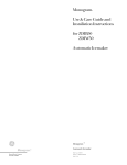
GasDowndraft Cooktop
Safety
Instructions
...................
3-5
Problem
Solver
..............................
21
More questions?...call
GEAnswer Center ® 800.626.2000
Operating
Instructions,
Tips
Controls ............................................................ 6
Cooktop Comparison .................................... 6
Cookware ........................................................ 7
Electric Ignition ............................................... 6
Installation
Instructions...
11-20
Converting to LP Gas .......................... 18-20
Downdraft ..................................................... 14
Features ....................................................... 5, 6
Using Your Cooktop .............................. 7, 8
Vent System ........................................... 8, 9
Consumer
Appliance
Care and Cleaning
......................
9, 10
Registration
..................23
................................. 2
Important Phone Numbers ....................... 23
Model and Serial Numbers ......................... 2
Warranty
I Moflels:
GEAppliances
Services
....................................... Back Cover
JGP640, JGP641
HELP
US HELP
YOU...
Read this guide carefully.
WARNING: If the information in this
guide is not followed exactly, a fire or
explosion may result causing property
damage, personal injury or death.
It is intended to help you operate and maintain your
new cooktop properly.
Keep it handy for answers to your questions.
If you don't understand something or need more help, call:
GE Answer Center _"_
800.626.2000
24 hours a day, 7 days a week
-- Do not store or use gasoline or other
flammable vapors and liquids in the
vicinity of this or any other appliance.
Write down the model and serial numbers.
You'll find the model and serial numbers on a label
located on the underside of the cooktop.
These numbers are also on the Consumer Product
Ownership Registration Card that came with your
cooktop. Before sending in this card, please write
these numbers here:
Model Number
Serial Number
Use these numbers in any correspondence
calls concerning your cooktop.
If you received
a damaged
or service
cooktop...
Immediately contact the dealer (or builder) that sold
you the cooktop.
Save time and money.
request service...
Before
--
WHAT
TO DO IF YOU
SMELL
GAS
• Do not try to light any appliance.
• Do not touch any electrical switch; do
not use any phone in your building.
• Immediately call your gas supplier from
a neighbor's phone. Follow the gas
supplier's instructions.
• If you cannot reach your gas supplier,
call the fire department.
-- Installation
and service must be
performed by a qualified installer,
agency or the gas supplier.
service
you
Check the Problem Solver in the back of this guide.
It lists causes of minor operating problems that you
can correct yourself.
IF YOU NEED SERVICE
To obtain service, see the Consumer
the back of this guide.
Services
page in
We're proud of our service and want you to be
pleased. If for some reason you are not happy with
the service you receive, here are three steps to follow
for further help.
FIRST, contact the people who serviced your
appliance. Explain why you are not pleased.
In most cases, this will solve the problem.
NEXT, if you are still not pleased, write all the
details--including
your phone number--to:
Manager, Consumer Relations
GE Appliances
Appliance Park
Louisville, KY 40225
FINALLY, if your problem is still not resolved,
Maior Appliance Consumer Action Program
20 North Wacker Drive
Chicago, IL 60606
2
write:
IMPORTANT
SAFETY INSTRUCTIONS
Read all instructions before using this app ance.
IMPORTANT SAFETY NOTICE
• The California Safe Drinking Water and Toxic
Enforcement Act requires the Governor of
California to publish a list of substances known to
the state to cause cancer, birth defects or other
reproductive harm and requires businesses to warn
customers of potential exposure to such substances.
• Gas appliances can cause minor exposure to
four of these substances, namely benzene, carbon
monoxide, formaldehyde and soot. caused primarily
by the incomplete combustion of natural gas or
LP fuels. Properly adjusted burners, indicated by
a bluish rather than a yellow flame, vdll minimize
incomplete combustion, Exposure to these substances
can be minimized further by venting with an open
window or using the ventilation fan.
When
You Get Your
Cooktop
When you get your cooktop, have the installer
show you the location of the gas cut-off valve
and how to shut it off if necessary.
• Have your cooktop installed and properly
grounded by a qualified installer, in accordance
with the Installation Instructions. Any adjustment
and service should be performed only by qualified
gas range installers or service technicians.
• Plug your cooktop into a 120-volt grounded
outlet only. Do not remove the round grounding
prong from the plug. If in doubt about the
grounding of the home electrical system, it is your
personal responsibility and obligation to have an
ungrounded outlet replaced with a properlygrounded three-prong outlet in accordance with
the National Electrical Code. Do not use an
extension cord with this appliance.
• Be sure all packing materials are removed from
the cooktop before operating it, to prevent fire or
smoke damage should the packing material ignite.
• Be sure your cooktop is correctly adjusted by a
qualified service technician or installer for the
type of gas (natural or LP) which is to be used.
Your cooktop can be converted for use with either
type of gas. See the Installation Instructions.
• Do not attempt to repair or replace any
part of your cooktop unless it is specifically
recommended in this guide. All other servicing
should be referred to a qualified technician.
WARNING---TO REDUCE THE RISK OF
FIRE, ELECTRIC SHOCK, OR INJURY TO
PERSONS, OBSERVE THE FOLLOWING:
A. Use this unit only in the manner intended
by the manufacturer. If you have questions,
contact the manufacturer.
B. Before Servicing or Cleaning the Unit. Switch
Power Off At Service Panel.
C. When cutting or drilling into wall or ceiling
do not damage electrical wiring and other
hidden utilities.
D. Ducted fans must alwavs be vented to the outdoors.
E. To reduce the risk of fire. use only metal ductwork.
V_RNING--TO
REDUCE
THE RISK
OF A COOKTOP
GREASE
FIRE:
A. Keep fan. filters
B. Always
and grease
laden surfaces
turn vent ON when cooking
clean.
at high heat.
C. Use high settings on cooktop only when necessary.
Heat oil slowly on low to medium setting.
D. Don't leave the cooktop
unattended
when cooking.
E. Always use cookware and utensils appropriate
for the type and amount of food being prepared.
CAUTION--For
General
Ventilating
Use Only.
Do Not Use To Exhaust
Hazardous
Or Explosive
Materials
and Vapors.
Using Your Cooktop
• Do not leave children alone or unattended
where a cooktop is hot or in operation. They
could be seriously burned.
• CAUTION: Items of interest to children should
not be stored in cabinets above a cooktop-children climbing on the cooktop to reach items
could be seriously injured.
• When raising or lowering the vent: Keep
fingers away from all vent parts; assure that
cookware, pans and handles will not be struck
and tipped when raising the vent.
• Do not operate or clean your cooktop if the
glass is broken or cracked. Cleaning solutions
and spillovers could penetrate the broken cooktop
and create a risk of electric shock. Call for service
immediately if the cooktop glass breaks or cracks.
• Clean the cooktop with caution. Ira wet sponge
or cloth is used to wipe spills on a hot cooktop, be
careful to avoid steam burns.
_continued
next page)
IMPORTANT
SAFETY INSTRUCTIONS
(continued)
• Do not clean the cooktop with flammable
volatile cleaning fluids.
or
• Do not clean the cooktop when the appliance
is in use.
• Avoid scratching the cooktop with shal_
instruments, or with rings and other jewelry
• Never use the cooktop as a cutting board.
• Let the burner grates and other surfaces cool
before touching them or leaving them where
children can reach them.
• Never wear loose-fitting or hanging garments
while using the appliance. Be careful when
reaching for items stored in cabinets over the
cooktop. Flammable material could be ignited if
brought in contact with flame or hot surfaces and
may cause severe burns.
• For your safety, never use your appliance for
warming or heating the room.
_0
• Do not use water on grease fires.
Never
pick
up a flaming
pan. a
Turn the
controls
off Smother
flaming pan on a surface burner by covering the
pan completely with a well-fitting lid, cookie
sheet or flat tray. Use a multi-purpose dry
chemical or foam-type fire extinguisher.
Flaming grease outside a pan can be put out
by covering it with baking soda or. if available.
by using a multi-pul_ose dry chemical or foamtype fire extinguisher.
• Do not store flammable materials near the
cooktop. Do not store or use gasoline or other
flammable vapors and liquids in the vicinity of
this or any other appliance.
'_
• Do not let cooking grease or other
flammable materials accumulate in
or near the cooktop.
• Never leave surface burners un attended at
high flame settings. Boilovers cause smoking
and greasy spillovers that may catch on fire
• Adjust surface burner flame size so it does
not extend beyond the edge of the cookware.
Excessive flame is hazardous
• Use only dry pot holders-moist or damp pot holders on hot
surfaces may result in burns from
steam. Do not let pot holders come near open
flames when lifting cookware. Do not use a towel
or other bulky cloth in place of a pot holder.
• To minimize the possibility of burns, ignition of
flammable materials and spillage, turn cookware
handles toward the side or center of the cooktop
without extending over adjacent burner or vent area
•Alwavs turn the surface burners to off before
removing the cookware.
• Carefully watch foods being fried at high
flame setting.
• Foods for frying should be as dry as possible.
Frost on frozen foods or moisture on fresh
foods can cause hot fat to bubble up and over the
sides of the pan.
• Use least possible amount of fat for effective
shallow or deep-fat frying. Filling the pan too
full of fat can cause spillovers when food is added.
• If a combination of oils or fats will be used
in frying, stir together before heating, or as fats
melt slowly.
• Always heat fat slowly, and watch as it heats.
• Use a deep fat thermometer whenever
possible to prevent overheating fat beyond
the smoking point.
• Use proper pan size--Avoid pans that are
unstable or easily tipped. Select cookware having
flat bottoms large enough to properly contain food
and avoid boilovers and spillovers, and large
enough to cover burner grate. This will both save
cleaning time and prevent hazardous accumulations
of food. since heavy spattering or spillovers left on
cooktop can ignite. Use pans with handles that can
be easily grasped and remain cool.
• Do not place hot cookware on the glass
cooktop. This could cause glass to break.
• Keep all plastics away from burners.
• To avoid the possibility of a burn, always be
certain that the controls for all burners are at
the off position and all grates are cool before
attempting to remove a grate.
• If the cooktop is located near a window,
do not use long curtains which could bloW
over the burners and create a fire hazard
• If you smell gas, turn off the gas to the cooktop
and call a qualified service technician. Never use
an open flame to locate a leak.
• Do not cover
or block the area around
the
cooktop knobs. This area must be kept clear for
proper ventilation and burner performance.
• When cooking pork, follow the directions
exactly and always cook the meat to an internal
temperature of at least 170°F. This assures that,
in the remote possibility that trichina may be
present in the meat. it will be killed and the meat
will be safe to eat.
° Do not use a wok on the cooking surface if
the wok has a round metal ring which is placed
over the burner grate to support the wok.
This ring acts as a heat trap which may damage
the burner grate and burner head. Also. it may
cause the burner to work improperly. This may
cause a carbon monoxide level above that allowed
by current standards, resulting in a health hazard.
SAVE THESE
INSTRUCTIONS
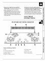
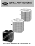
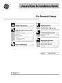
FEATURES
OF YOUR COOKTOP
/
Models
JGP640
and JGP641
1. Vent
6. Fan Speed Control
2. Vent Filters (behind the grille)
7. Vent Control
3. Cast-Iron
8. Surface Unit Controls
4. Spillproof
Burner
Grates
Burners
5. High Power Spillproof
9. Glass Cooktop
Burners
Surface
(continued
next
page)
5
FEATURES
OF
YOUR
COOKTOP
(continued)
Electric
Ignition
Auto Relight
All of the burners on this cooktop are equipped with
electric igniters that eliminate the need for standing
pilot lights.
All the igniters make clicking sounds and spark even
when only a single burner is being turned on. Do not
touch any of the burners when the igniters are clicking.
The burners on this cooktop relight automatically
if the flame goes out. This helps prevent the
inconvenience
of having to manually relight a burner.
As with electric ignition, all of the burner igniters
spark while a burner is relighting. Do not touch any
of the burners when the igniters are clicking.
Vent
The vent may be left in any position between fully extended and fully
closed but the fan will only operate in the fully extended position.
HOW DOES THIS COOKTOP COMPARE
TO YOUR OLD ONE?
Your new cooktop has gas burners. If you are used
to cooking with induction or other electric surface
units, you will notice some differences when you use
gas burners.
The best types of cookware to use, plus heat-up and
cool-down times, depend upon the type of burner or
surface unit you have.
The following chart will help you to understand the
differences between gas burner cooktops and any
other type of cooktop you may have used in the past.
Type of Cooktop
Description
How it Works
Gas Burners
Regular or sealed
gas burners use
either LP gas
or natural gas.
Flames heat the pans directly. Pan flatness is not critical to cooking results, but
pans should be well balanced. Gas burners heat the pan right away and change
heat settings right away. When you turn the control off, cooking stops right away.
Radiant
(Glass Ceramic)
Cooktop
Electric coils
under a glassceramic cooktop.
Heat travels to the glass surface and then to the cookware, so pans must be flat on
the bottom for good cooking results. The glass cooktop stays hot enough to
continue cooking after it is turned off. Remove the pan from the surface unit if
you want cooking to stop.
High frequency
induction coils
under a glass
surface.
Pans must be made of ferrous metals (metal that attracts
produced by a magnetic circuit between the coil and the
and changes heat settings right away, like a gas cooktop.
off, the glass cooktop is hot from the heat of the pan, but
Electric Coil
Flattened metal
tubing containing
electric resistance
wire suspended
over a drip pan.
Heats by direct contact with the pan and by heating the air under the pan. For best
cooking results, use good quality pans. Electric coils are more forgiving of
warped pans than radiant or solid disks. Heats up quickly but does not change
heat settings as quickly as gas or induction. Electric coils stay hot enough to
continue cooking for a short time after they are turned off.
Solid Disk
Solid cast iron
disk sealed to the
cooktop surface.
Heats by direct contact with the pan, so pans must be flat on the bottom for good
cooking results. Heats up and cools down more slowly than electric coils. The
disk stays hot enough to continue cooking after it is turned off. Remove the pan
from the solid disk if you want the cooking to stop.
©
Induction
_xx\mlto/
@
6
a magnet). Heat is
pan. Heats up right away
After turning the control
cooking stops right away.
USING
Electric
YOUR
COOKTOP
Ignition
Your surface burners are lighted by electric ignition,
eliminating the need for standing pilot lights with
constantly burning flames.
Surface burners in use when an electrical power
failure occurs will continue to operate normally.
r_
In case of a power outage, you can light the surface
burners on your cooktop with a match. Hold a lighted
match to the burner, then turn the knob to the HIGH
position. Use extreme caution when lighting
burners this way.
To Light a Burner
Push the control knob in
and turn it counterclockwise
to desired position from
HIGH to LOW.
• The two rear burners are best for smaller pans
and cooking operations requiring carefully
controlled simmering conditions. The two front
burners are the high power burners for larger pans
and fast boiling operations.
After the burner ignites,
turn the knob in either
direction to adjust the
flame size.
oo
oo
• Do not operate a burner for an extended period
of time without cookware on the grate. The finish
on the grate may chip without cookware to absorb
the heat.
• Check to be sure the burner you turned on is the
one you want to use.
To turn a burner off,
turn the knob clockwise,
as far as it will go, to the
OFF position.
• Be sure the burners and grates are cool before you
place your hand, a pot holder, cleaning cloths or
other materials on them.
_o
How to Select Flame
r_
Size
Watch the flame, not the
knob, as you reduce heat.
FOR SAFE HANDLING OF COOKWARE,
NEVER
LET THE FLAME EXTEND UP THE SIDES OF
The flame size on a gas
burner should match the
cookware you are using.
THE COOKWARE.
Any flame larger than the bottom
of the cookware is wasted heat and only serves to heat
the handle.
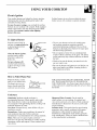
Cookware
r_
_o
Aluminum:
Medium-weight
cookware is
recommended
because it heats quickly and evenly.
Most foods brown evenly in an aluminum skillet.
Use saucepans with tight-fitting lids for cooking with
minimum amounts of water.
Cast Iron: If heated slowly, most skillets will give
satisfactory results.
Enamelware:
Under some conditions, the enamel of
some cookware may melt. Follow cookware
manufacturer's
recommendations
for cooking methods.
Glass: There are two types of glass cookware-those for oven use only and those for surface cooking
(saucepans, coffee and teapots). Glass conducts heat
very slowly.
Heatproof
Glass Ceramic:
Can be used for
either surface or oven cooking. It conducts heat
very slowly and cools very slowly. Check cookware
manufacturer's
directions to be sure it can be used
on gas cooktops.
Stainless Steel: This metal alone has poor heating
properties, and is usually combined with copper,
aluminum or other metals for improved heat
distribution. Combination metal skillets generally
work satisfactorily
if they are used at medium heat
as the manufacturer recommends.
(continued
next page)
7
USING YOUR COOKTOP
(continued)
Wok Cooking
We recommend that you
use only a flat-bottomed
wok. They are available
at your local retail store.
N__//
Do not use woks that have
_N_a
_J_
support rings. Use of these types
of woks, with or without the ring
in place, can be dangerous.
Placing the ring over the burner
,_o
_
grate may cause the burner to work improperly
resulting in carbon monoxide levels above allowable
current standards. This could be dangerous to your
health. Do not try to use such woks without the ring.
You could be seriously burned if the wok tipped over.
Stove Top Grills
_!iiiiiiiiii_
....
,_iii!iii_,
Do not use stove top grills on your sealed gas burners. If you use the stove
top grill on the sealed gas burner it will cause incomplete combustion and
can result in exposure to carbon monoxide levels above allowable current
standards. This can be hazardous to your health.
COOKTOP VENT SYSTEM
The built-in vent system helps remove cooking vapors, odors and smoke
from foods prepared on the cooktop. Continuous use of the vent system
helps keep the kitchen comfortable and less humid, reducing cooking odors
and soiling moisture that normally creates a frequent need for cleaning.
How to Operate
the Vent System
To raise the vent, turn the
VENT knob to RAISE.
Hold the knob at the RAISE
position until the vent is fully
extended. The vent will
automatically
stop when it
is fully extended or when the
VENT knob is released.
To lower the vent, turn the VENT knob to LOWER.
Hold the knob at the LOWER position until the vent is
completely lowered and the flap is closed.
LOWE_AtSE
The vent may be left in any position between fully
extended and fully closed but the fan will only operate
in the fully extended position.
VENT
Turn the FAN knob to HIGH position to turn it on.
OFF
If you continue turning the FAN knob, you can select
a fan speed between HIGH and LOW.
The FAN knob does not have to be turned to OFF
before the vent is lowered. The fan will automatically
turn off when the VENT LOWER position is selected.
If the fan was not turned off when the vent was
lowered, it will automatically come on at the previously
selected speed when the vent is fully raised.
8
LO!@
!elGH
FAN
CAUTION:
Be careful when raising or lowering
the vent. Be sure pots, pot handles and other objects
are clear of the vent cover and cannot be struck or
tipped by the vent being raised. Keep hands and
fingers away from all vent parts.
CARE AND CLEANING
Proper care and cleaning are important so your cooktop
will give you efficient and satisfactory service. Follow
these directions carefully in caring for it.
Control Knobs
The control knobs may be removed
for cleaning.
Before cleaning any part of your cooktop, be sure all
burners are off and DISCONNECT
ELECTRICAL
POWER TO THE COOKTOP
at the fuse box or
circuit breaker panel, or pull the cooktop power plug,
located beneath the cooktop and inside the cabinets.
To remove a knob, pull it straight
up.
Wash the knobs in soap and water but do not soak.
Avoid getting water down into the knob stem holes.
Glass Cooktop
To keep the cooktop looking its best, wipe up any
spills as they occur. This will keep them from burning
on and becoming more difficult to remove.
As soon as the cooktop is cool, wash the glass surface
with a cloth moistened with warm, soapy water; rinse
with clean water, and dry with a soft cloth. You can use
any liquid household detergent. Do not use abrasive
materials such as metal pads, cleansing powder and
scouring pads--they may scratch the surface. Do not use
harsh chemicals such as bleach or chemical oven cleaners.
CAUTION:
DO NOT COOK ON OR CLEAN A
BROKEN OR CRACKED
COOKTOP.
Cleaning
solutions and spillovers penetrating the cooktop can
create a risk of electric shock. Call for a service
technician immediately.
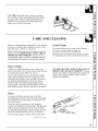
Filters
To remove the filters, raise the vent to the fully
extended position. Remove the front grille by pulling
the top edge forward and lifting away the panel. Lift
out the two filters.
Clean the filters by agitating in a hot detergent
solution or wash them in the dishwasher. The efficiency
of the vent system depends on how clean the filters
are. The filters can become soiled in a short time and
should be cleaned frequently for best performance.
After cleaning,
replace
\
the filters and the front grille.
(continued
next page)
9
CARE AND CLEANING
(continued)
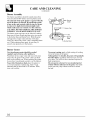
Burner Assembly
The burner assemblies should be wiped clean often.
Turn all controls OFF before removing burner parts.
The electrode of the spark igniter is exposed when the
top of the burner is removed. Be careful not to push
in any surface unit controls while the top of a burner
is removed. A slight electrical shock might result
which could cause you to knock over hot cookware.
CAUTION: DO NOT OPERATE THE BURNER
WITHOUT ALL BURNER PARTS IN PLACE.
The burner grates and caps can be lifted off, making
them easy to clean. Removing them gives you access
to the burner base and burner bowl. Wash the grate
and cap in hot, soapy water and rinse with clean
water. Dry them with a cloth--don't
reassemble them
wet. When replacing these parts, be sure they fit
securely into position over the burners.
Burner
'__
Grate
i
!_--I--
_Burner
Burner Cap
s,ot
Bowl
Grates
Cast-iron
burner grates should be washed
regularly and of course, after spillovers.
Wash them in hot, soapy water and rinse with clean
water. Dry the grates with a cloth--don't
put them
back on the cooktop wet. When replacing the grates,
be sure they're positioned securely over the burners.
To get rid of burned-on
food, place the grates in
a covered container or plastic bag. Add 1/4 cup
ammonia and let them soak for 30 minutes. Wash,
rinse well, and dry.
10
Burner
To prevent rusting, apply a light coating of cooking
oil on the bottom of the grates.
Although they're durable, the grates will gradually
lose their shine, regardless of the best care you can
give them. This is due to their continual exposure to
high temperatures.
Do not operate a burner for an extended period
of time without cookware on the grate. The finish
on the grate may chip without cookware to absorb
the heat.
BEFOREYOU BEGIN
Read these instructions
completely and
carefully.
IMPORTANT-OBSERVE
ALL GOVERNING
CODES AND ORDINANCES.
NOTE TO INSTALLER: Be sure to leave
these instructions
with the consumer.
PARTSLIST
Cooktop
• 4 burner grates
• 4 burner caps
• Pressure regulator with attached 1/2" to 3/8"
reducing bushing and 3/8" pipe nipple
• 2 clamping brackets with screws
• Attached 120 volt grounded plug cord
• Self adhesive gasket
1/4" x 36" (1)
3/16" x 36" (2)
Downdraft Unit
• Downdraft unit
• Downdraft stability brackets
• Two filters
• Removable grille
• Adapter flange
Blower Unit-JXDV66-vent kit not supplied
(This cooktop must be used in conjunction with
blower unit JXDV66.)
• Blower
• Nuts and washers
TOOLSAND PARTSNEEDED
• Large fiat blade screwdriver
• Saw
• Carpenter's square
• Pipe wrench
• Gas line shut-off valve
• Pipe joint sealant that resists action of LP gas
For flexible connection where local
codes permit:
• Flexible metal tubing (same 3/4" or 1/2" I.D.
as gas supply line)
• Flare union adapter for connection to supply line
(3/4" NPTx 3/4" I.D. or 1/2" NPTx 1/2" I.D.)
• Flare union adapter for connection to regulator
(1/2" NPTx 3/4" I.D. or 1/2" I.D.)
For rigid connection:
• Pipe fittings as required
IMPORTANT SAFETYINSTRUCTIONS
The cooktop has been design certified by the
American Gas Association. As with any appliance
using gas and generating heat, there are certain
safety precautions you should follow. You'll find
these precautions in this Use and Care Guide;
read it carefully.
• Be sure your cooktop is installed properly
by a qualified installer or service technician.
• The cooktop must be electrically grounded in
accordance with local codes, or in their absence,
with the National Electrical Code ANSI/NFPA
No. 70-Latest Edition.
• Installation of this cooktop must conform with local
codes, or in the absence of local codes, with the
National Fuel Gas Code. ANSI Z223.1-Latest Edition.
• Disconnect electrical supply before servicing.
• Make sure the wall coverings around the cooktop can
withstand heat generated by the cooktop up to 200°E
• Avoid placing cabinets above the cooktop. To
reduce the hazard caused by reaching over the
open flames of operating burners, install a
ventilation hood over the cooktop that projects
forward at least 5" beyond the front of the cabinets.
• If cabinets are placed above the cooktop, allow
a minimum clearance of 30" between the cooking
surface and the bottom of unprotected cabinets.
• If a 30" clearance between cooking surface and
overhead combustible material or metal cabinets
cannot be maintained, protect the underside of
the cabinets above the cooktop with not less
than 1/4" insulating millboard covered with
sheet metal not less than 0.0122" thick.
• Clearance between the cooking surface and
protected cabinets MUST NEVER BE LESS THAN
24". The vertical distance from the plane of the
cooking surface to the bottom of adjacent overhead
cabinets extending closer than 1" to the plane of the
cooktop sides must not be less than 18". (See
Dimensions and Clearances illustration in this section.)
FORYOUR SAFETY
IF YOU SMELLGAS:
!. Open windows.
2. Don't touch any electrical switches.
3. Extinguish any open flame.
4. Immediately call your gas supplier.
FORYOUR SAFETY
Do not store or use gasoline or other
flammable vapors and liquids in the vicinity
of this or any other appliance.
(continued
next page)
11
STEP!
STEP2
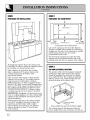
PREPARINGFORINSTALLATION
PREPARINGTHECOUNTERTOP
t
Not less than 1¼"
21_"
25
I'
34%Z'
8_0 " min.
cut-out to wall
t
8_%6
" min.
cut-out to wall
Not less than 2¼"
Countertop
cut-out
dimensions
Cut out the opening as shown in the diagram.
Measure carefully when cutting the countertop,
making sure the sides of the opening are parallel
and the front and rear cuts are exactly
perpendicular
to the sides.
The front of the opening must clear the front
support rail on the cabinet and the rear of the
opening must clear the rear support of the cabinet.
Avoid placing cabinets above the cooktop unit,
if possible, in order to reduce the hazards caused
by reaching over heated surface units.
If the cabinetry is used above the cooktop,
allow a minimum 30" clearance between the
cooking surface and the bottom of the
unprotected cabinet.
If the clearance between the cooktop and the
cabinetry is less than 30", the cabinet bottom
must be protected with a flame retardant
millboard at least 1/4" thick, or gypsum board
at least 3/16" thid{, covered with 28 gauge sheet
steel or 0.020" thid{ copper. Clearance between
the cooktop and the protected cabinetry must
NEVER BE LESS THAN 24". Cabinetry above
a cooktop must not be more than 13" in depth.
EXCEPTION: Installation of a listed microwave
oven or cooking appliance over the cooktop shall
conform to the installation instructions pad{ed
with that appliance.
Working areas adjacent to the cooktop should
have an 18" minimum clearance between the
countertop and the bottom of the cabinet.
If the clearance is less than 18", the adjacent
cabinets should be at least 8" from the side
of the cooktop.
12
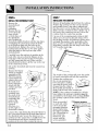
STEP3
GASAND ELECTRICALLOCATION
The position of the electrical supply receptacle
and the gas supply pipe entering the cabinet
should be positioned as shown in the shaded
areas marked below. The cooktop is equipped
with a 4' power cord, which should reach any
desired location on the cabinet walls.
Power receptacle
[] Gas inlet
Areas
suitable
for gas and electricity
The cooktop must be disconnected
power supply before any servicing
supply
from the
is carried out.
STEP4
PROVIDEADEQUATEGASSUPPLY
This cooktop is designed to operate on natural gas
at 4" of water column pressure or on LP gas at 10"
of water column pressure. It is shipped from the
factory set for natural gas. If you decide to use
this cooktop with LP gas, conversion adjustments
must be made by a service technician or other
qualified person.
A pressure regulator is to be connected in series
with the manifold of the cooktop and must
remain in series with the supply line regardless
of whether natural or LP gas is being used.
For proper operation, the maximum inlet
pressure to the regulator must be no more
than 10" water column pressure for natural
gas, or 14" water column pressure for LP
gas. For checking the regulator, the inlet
pressure must be at least 1" greater than the
regulator output setting. If the regulator is set
for 4" of water column pressure, the inlet
pressure must be at least 5". If the regulator is
set for 10", the inlet pressure must be at least 11".
For ease of installation, and if local codes permit,
the gas supply line into the cooktop should be
1/2" or 3/4" I.D. flexible metal appliance
connector three to five feet in length.
STEP5
Cut hole in the cabinet wall or floor as
appropriate for your installation. Make sure
the exhaust duct is located between wall studs or
the floor joists.
Cut only one hole in the cabinet, depending
the route of the ductwork.
The location of the hole is different
left and right side venting.
on
for
Back
7_o"
PREPAREFOR DUCTWORK
NOTE: Ductwork MUST be vented outside.
DO NOT vent into a wall, ceiling, crawlspace,
attic or any concealed space.
Determine the best route for ductwork;
it can be routed in a variety of ways, depending
on the kitchen layout.
Vented through
to the outside.
the left side of the cabinet
Back
Throu_ 'h wall to roof
Directly through wall
Vented through the right side of the cabinet
to the outside.
Direct to rear wall
Between
floor joists
(continued next page)
13
STEP6
STEP7
INSTALLTHE DOWNDRAFTUNIT
Remove the
INSTALLINGTHE COOKTOP
downdraft
from the
unit
packaging.
Remove the two
screws from the
front of both
vertical edges of
the downdraft
unit. Position the
downdraft stability brackets with the top edges
overlapping the countertop so that the holes
in the brackets align with the holes in the
downdraft unit. Replace the screws. Peel the
backing from the thicker (1/4") of the gasket
strips and apply to the top front edge of the
downdraft unit.
Remove all packaging
material from the cooktop.
Position the cooktop over the cut-out opening
and carefully lower it into place, making sure
that the power cord is dropped into the cabinet.
Make sure the cooktop location is all the way to
the front of the countertop
cut-out. Lift out the
cooktop from the countertop
opening.
Cut one of the remaining
gasket strips in half
(these are to be used as the side strips). Peel
the backing from the self adhesive gasket strips,
and apply the gaskets to the underside of the
glass, as close as possible to the edge without
protruding,
ensuring the side strips end at least
3/8" from the back edge.
1/16--'-f/,-..
Carefully lower the unit into its position at the
back of the cut-out so that the flanges on the
back edge of the unit and on the two brackets
are fully supporting
the unit. Make sure the
downdrafl unit location is all the way to the rear
of the countertop
cut-out.
Lift out the downdrafl
opening.
unit from the countertop
Remove the blower
(which is supplied
separately
as kit
JXDV66) from its
carton and fit the
adapter plate onto
the studs of the
blower housing-attach with the
washers
and nuts
provided.
Fit the blower
assembly onto
the studs of the
downdraft unit,
positioning
the
outlet of the
blower in the
required
direction--i.e.,
for left, right or
downwards
venting.
Connect the 3 pin plastic plug from the blower to
the 3 pin socket located at the right hand side of
the downdraft unit. Secure the metal cover in
position over the connection.
Carefully lower the
downdraft unit and blower assembly into its
position at the rear of the countertop cut-out.
14
The weight of the cooktop will cause the gasket
to form a watertight
seal with the countertop.
Position the cooktop over
the cut-out opening and
lower into place, making
sure that the power cord is
dropped into the cabinet.
Press gently and evenly to
firmly seat the unit in the countertop.
NOTE: If the cooktop is installed in a 36 inch
base cabinet, the pressure
regulator
must be
assembled
to the bottom of the cooktop before
the cooktop is placed in the cabinet. Refer to
Step 8.
Slots are provided
on each side of the
case to accept the
mounting brackets.
Insert bracket into
the highest available
slot, (depending
on
the countertop
thickness),
and
secure with the
screws provided.
--_.......
,4"
STEP7 (continued)
Appropriate
flare union
each end of the flexible
INSTALLINGTHE COOKTOP
NOTE: If the cooktop is installed in a 36" base
cabinet, the mounting
brackets cannot be used
because
of the interference
with the sides of the
cabinet. In this case, the cooktop can be secured
to the sides of the cabinet using angle brackets
(not supplied).
Remove one screw at the bottom
of the cooktop body, on each side, then replace
to hold the bracket to the cooktop. Then secure
the brackets
to the cabinet sides with the screws
provided.
Connect the 9-pin plastic plug from the downdraft
unit to the 9-pin plastic socket situated adjacent
to the power cord on the cooktop. Secure the
metal cover in position over the connection.
9-Pin Socket
adapters
are required
connector.
at
Turn on the gas; check for leaks using a liquid leak
detector at all joints in the system (the pressure
test nipple is adjacent to the gas inlet pipe on the
rear right hand side of the cooktop bottom).
CAUTION: DO NOT USE A FLAME TO
CHECK FOR GAS LEAKS.
IMPORTANT-Disconnect
the cooktop and
the individual shut-off valve from the gas supply
piping system during any pressure
testing of that
system at test pressures
greater than 1/2 psig.
Isolate the cooktop from the gas supply piping
system by dosing the individual manual shut-off
valve to the cooktop during any pressure
testing
of the gas supply piping system at test pressures
equal to or less than 1/2 psig.
Service Plate
Electrical
Pressure
Test Point
STEP9
INSTALLTHE DUCTWORK
Supply Cord 9-Pinplug
"_
Metal Cover "_-!_
,Pressure
Regulator
_--_-_1;
Layout
of Service
Panel
STEP8
GASCONNECTION
Install the supplied pressure
regulator
and nipple in the gas
line as close to the cooktop inlet
as possible, making allowances
for
ventilation
ducting as necessary.
Make sure the regulator
is
installed in the right direction.
Install a manual shut-off valve in
the gas line in an easily accessible
location, as close to the pipe stub
as possible, making allowances
for
the ventilation
ducting. Be sure
you know how and where to shut
off the gas supply to the cooktop.
NOTE: Instead of using solid
piping to connect to pressure
regulator, an approved
flexible
metal appliance connector
may be
used between the pipe stub and
shut-off and the pressure
regulator, if local codes permit.
Use minimum 26 gauge galvanized or 24 gauge
aluminum duct in 6" round or 31/4"x 10" size, or
a combination of both. PVC duct should be used
if installing under a poured concrete slab. DO
NOT use flexible ducting.
Always use an
appropriate
roof
or wall cap with
damper. Laundry
type wall caps
should never be
used. Use the
straightest
duct
run possible.
For satisfactory
performance
the duct run should not exceed
75 ft. or its equivalent
length if bends or other
various fittings are used. Refer to table of
equivalent lengths for various duct configurations.
Install ductwork so that the piece of duct nearest
the downdraft unit slots INTO the next piece of
duct. Secure all joints with self tapping screws
and apply duct tape around the joint to ensure an
airtight seal.
(continued next page)
15
Duct Pieces
Equivalent
Length*
Number
Used
Total
Equivalent
Length
1ft.
6" round,
straight
(per foot
length)
3¼"x 10"
straight
(per foot
length)
6",
90°
elbow
15ft.
6",
45 °
elbow
9ft.
3¼"x
10"
90
° elbow
16ft.
3¼"x
10"
45
° elbow
5ft.
3¼"x 10"
90 ° flat elbow
18ft.
i_
to 3¼"x 10"
6" round
transition
7ft.
I_
to 6" round
3¼"x 10"
transition
5ft.
[_
to 3¼"x 10"
transition
6" round
90 ° elbow
20 ft.
[_
to 6" round
transition
3¼"x
10"
90 ° elbow
feel
1ft.
(_
(_
(_
The power cord of this appliance is equipped
with a three-prong (grounding) plug which
mates with a standard three-prong grounding
wall receptacle to minimize the possibility of
electric shock hazard from this appliance. The
customer should have the wall receptacle and
circuit checked by a qualified electrician to make
sure the receptacle is properly grounded and has
correct polarity.
Where a standard two-prong wall receptacle is
encountered, it is the personal responsibility and
obligation of the customer to have it replaced
with a properly grounded three-prong wall
receptacle in accordance with the National
Electrical Code.
Do Not, Under Any Circumstances,
Cut Or Remove The Third (ground)
Prong From The Power Cord.
Do not use an extension cord with this appliance.
3¼ " x lO"wall
ap with damper
27 ft.
6" round
roof cap
20 ft.
24 ft.
Total ducl
run
* Equivalent lengths of duct pieces are based
on actual tests conducted by GE Evaluation
Engineering and reflect requirements for good
venting performance with any downdrafl cooktop.
16
Electrical requirements:
120 volt, 60 Hertz, individual, properly grounded
branch circuit protected by a 15 amp circuit
breaker or time delay fuse.
GROUNDING
IMPORTANT: (Please read carefully.)
FOR PERSONAL SAFETY, THIS APPLIANCE
MUST BE PROPERLY (;ROUNDED.
12ft.
21ft.
Should not exceed 75 ft
ELECTRICALCONNECTION
STEP!!
6" round walt
cap damper
6" round
roof vent
feel
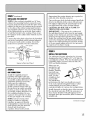
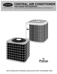
STEP!0
CHECKIGNITION
Assemble burners
as shown. All
parts are keyed
and only fit one
way. Push in one
knob and turn to
HIGH position,
(90° from OFF).
The igniter will
spark and the
burner will light;
the igniter will
cease sparking
when the burner
is lit. Turn the
knob to OFF
position; repeat
procedure for each burner.
Top grate
Burner
Cap
STEP12
CHECKOPERATIONOF DOWNDRAFT
To raise the vent, turn the VENT knob to RAISE.
Hold the knob at the RAISE position until the
vent is fully extended.
The vent will automatically
stop when it is fully extended
or when the VENT
knob is released.
Remove the ventilator
grille, remove the filters
and packaging
and replace the filters.
Turn the EAN knob
turn it on.
to HIGH position
to
If you continue turning the EAN knob, you can
select a fan speed between HIGH and LOW.
To lower the vent, turn the VENT knob to
LOWER. Hold the knob at the LOWER position
until the vent is completely
lowered and the flap
is dosed.
17
This cooktop leaves the factory set for use with
natural gas. If you convert to LP gas, keep these
instructions
and orifices in case you want to convert
back to natural gas.
The conversion
should
technician
or installer.
be done by a qualified
PARTS:
Check the contents of the kit, which should
contain the following:
• 2 Orifice--Large
size--104-WB28K0093
• 2 Orifice--Regular
size--82-WB28K0094
• 1 Maxitrol LP adapter--WB01K055
• 1 Tie-on card/label for regulator
Ifyou do not have all the above listed components,
or if you are in any doubt, please contact the nearest
GE Service and Parts Center.
USE ONLY APPROVED PIPE DOPE RESISTANT
TO LP GAS.
Total input rating after conversion:
• 4 burner cooktop 34,000 Btu/hr.
TOOLSREQUIRED:
Adjustable wrench
Nut drivers: 9/32" or 7 mm
[_
PREPARE COOKTOP FOR CONVERSION
(1) Turn off gas supply at the wall.
(2) Turn off the electrical power to the cooktop.
18
_1 CONVERTTHE SURFACEKNOBS
1. Remove the knobs and
lift off the microswitch
operating cams from
the valve shafts.
o__
/
Cam
Shaft
Valve
,__
•
,
o
.
2. Fully screw down the
brass low flame
adjustment screws into
the valve bodies with a
clockwise rotation.
3. Replace the knobs
and cams.
LO
[]
CONVERTTHE SURFACEBURNERS
CONVERTTHE PRESSUREREGULATOR
Top Grate
Burner Cap
@
1. Remove grates and burner caps.
2. Using the 7 mm nut driver,
remove and replace the brass
orifice spud inside each burner
chimney as follows:
• Replace the large orifices with
the spuds that are stamped 104.
• Replace the small orifices with
the spuds that are stamped 82.
I
WARNING: Do not remove the pressure
regulator from the cooktop.
1. Locate the pressure regulator under the rear of
the cooktop.
2. Use an adjustable wrench to remove the
nut from the pressure regulator.
\
-_
_
,___
Gas Flow
into Range
LP
t
NAT_
-_
Nut
3. Insert the LP Adapter into the nut.
NAT
LP
i
NOTE: There will be one
extra orifice spud when
converting
a four burner cooktop.
Nut --__
4. Reinsert the assembly into the regulator and
attach the tie-on label to the regulator using the
string provided.
(continued next page)
19
[_ CHECKFOR LEAKS
[_
When all connections
have been made, make
sure all cooktop controls are in the OFF position
and turn on the main gas supply valve. Use a
liquid leak detector at all joints and connections
to check for leaks in the system.
The combustion
to be determined
CAUTION: DO NOT USE A FLAME TO
CHECK FOR GAS LEAKS.
When using test pressures greater than 1/2 psig
to pressure test the gas supply system of the
residence, disconnect the cooktop and individual
shut-off valve from the gas supply piping. When
using test pressures of 1/2 psig or less to test the
gas supply system, simply isolate the cooktop from
the gas supply system by closing the individual
shut-off valve.
CHECK QUALITY OF FLAMES
quality of burner
visually.
flames
needs
(A) Yellow flames-Call for service
I
(B) Yellow tips on
outer cones-Normal for LP gas
(C) Soft blue flames-Normal for natural gas
If burner flames look like (A), call for service.
Normal burner flames should look like (B) or
(C), depending on the type of gas you use.
With LP gas, some yellow tipping on outer
cones is normal.
J-_ FINAL STEPS
Fill in the date plus the name and address of the
service organization performing
the conversion
in the spaces provided on the conversion
label.
Remove the backing from the label and stick it in
a convenient
place on the underside
of the
cooktop near the Rating Plate. Make sure the
area is clean and dry before applying the label.
The conversion
is now complete.
20
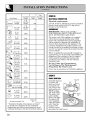
QUESTIONS?
USE THIS PROBLEM SOLVER
PROBLEM
BURNERS
LIGHT
POSSIBLE
DO NOT
CAUSE
• Make sure electrical
plug is plugged
• Slot in burner base may be clogged.
• Burner parts not replaced correctly.
into a live power outlet.
Remove
the obstruction.
• Hole in burner cap behind igniter may be clogged.
BURNERS HAVE
YELLOW OR
YELLOW-TIPPED
FLAMES
(A) Yellow flames -Call for service
(B) Yellow tips on outer
cones -- Normal for
LP gas
(C) Soft blue flames
Normal for
natural gas
• If burner flame looks like (A), call for service. Normal burner flames
should look like (B) or (C), depending on the type of gas.
BURNER FLAMES VERY
LARGE OR YELLOW
• If cooktop is connected to LP gas. check all steps in
the Installation Instructions.
BURNER CONTROL
KNOB WILL NOT TURN
• When the knob is at the OFF position, it must be pushed in before it can be
turned, and it can only be turned in a counterclockwise
direction. When the
knob is at any other position, it can be turned in either direction without being
pushed in.
FAN DOES
NOT WORK
• The vent must be fully extended before fan will work.
• Fan control knob must be turned in clockwise direction
to turn fan on.
If you need more help...call toll free:
GE Answer Center _"_
800.626.2000
consumer information
service
21
NOTES
22
We'll Be There
With the purchase of your new GE appliance, receive the assurance that if you ever need
information or assistance from GE, we'll be there. All you have to do is call-toll-free!
GEAnswerCenter®
800.626.2000
Whatever your question about any GE major appliance, GE Answer Center ®
infbrmation sets_ice is available to help. Your call-and your question-will
be
answered promptly and courteously. And you can call any time. GE Answer
Center ®set_ice is open 24 hours a day, 7 days a week.
In-HomeRepairService
800-GE-CARES
(800432-2737)
A GE consumer smvice professional will provide expert repair sexs_ice,
scheduled at a time that's convenient for you. Many GE Consumer Sets_ice
company-operated
locations offer you sets_ice today or tomorrow, or at your convenience (7:00 a.ln. to 7:00 p.m. weekdays, 9:00 a.m. to 2:00 p.m. Saulrdays).
Our fhctoxy-trained technicians know your appliance inside and out-so most
repairs can be handled in just one visit.
ForCustomersWith SpecialNeeds...
800.626.2000
I
SECTIONA-A
Upon request, GE will provide
Braille controls fbr a variety of GE
appliances, and a brochure to
assist in planning a barrier-fl'ee
kitchen for persons with limited
1nobility. To obtain these items,
fl'ee of charge, call 800.626.2000.
Consumers with impaired hearing or speech who hm_e
access to a TDD or a conventional
teletypewriter m W
call 800-TDD-GEAC (800-833-4322) to request
information
or service.
ServiceContracts
800-626-2224
You can have the secure feeling that GE Consumer Sexvice will still be there
after your warranty expires. Purchase a GE contract while your warranty is still
in effect and you'll receive a substantial discount. With a lnultiple-year contract,
you're assured of fllulre service at todw's prices.
PartsandAccessories
800-626-2002
Individuals qualified to service their own appliances
can have parts or accessories sent directly to their holne.
The GE parts system provides access to over 47,000
parts...and all GE Genuine Renewal Parts are fldly
warranted. VISA, MasterCard and Discover cards
are accepted.
User maintenance
instructions
contained
in this guide
cover procedures
intended
to be performed
by any user.
Other servicing generally should be referred
to qualified
service personnel.
Caution must be exercised,
since
improper
servicing may cause unsafe operation.
_o
Staple sales slip or cancelled check
here. Proof of original purchase date
is needed to obtain service
under warranty.
YOUR GE COOKTOP
WARRANTY
WHAT IS COVERED
FULL ONE-YEAR WARRANTY
For one year from date of original
purchase, we will provide, free of
charge, parts and service labor in
your home to repair or replace
any part of the cooktop that fails
because of a manufacturing
defect.
This warranty is extended to
the original purchaser and any
succeeding owner for products
purchased for ordinary home use
in the 48 mainland states, Hawaii
and Washington, D.C. In Alaska the
warranty is the same except that it
is LIMITED because you must pay
to ship the product to the service
shop or for the service technician's
travel costs to your home.
All warranty service will be
provided by our Factory Service
Centers or by our authorized
Customer Care ® servicers during
normal working hours.
Should your appliance need
service, during warranty period or
beyond, call 800-GE-CARES
(800-432-2737).
WHAT IS NOT COVERED
Service trips to your home to teach
you how to use the product.
• Replacement of house fuses or
resetting of circuit breakers.
Read your Use and Care material.
If you then have any questions
about operating the product,
please contact your dealer or our
Consumer Affairs office at the
address below, or call, toll free:
• Failure of the product if it is used
for other than its intended purpose
or used commercially.
GE Answer Center _
800.626.2000
consumer information service
WARRANTOR IS NOT
RESPONSIBLE FOR
CONSEQUENTIAL DAMAGES.
• Damage to product caused
by accident, fire, floods or acts
of God.
Improper installation.
If you have an installation problem,
contact your dealer or installer.
You are responsible for providing
adequate electrical, gas, exhausting
and other connecting facilities as
described in the Installation
Instructions provided with the
product.
Some states do not allow the exclusion or limitation of incidental or consequential damages, so the above limitation or exclusion
may not apply to you. This warranty gives you specific legal rights, and you may also have other rights which vary from state to state.
To know what your legal rights are in your state, consult your local or state consumer affairs office or your state's Attorney General.
Warrantor:
General Electric Company
If further help is needed concerning this warranty, write:
ManagermConsumer Affairs, GE Appliances, Louisville, KY 40225
Part No. 183D5580P001
Pub No. 49-8713
10-95
CG
JGP640
JGP641
Printed in Mexico