1
Operator's Manual
Transmatic Lawn Tractor
Models 660 - 688
IMPORTANT:
READ SAFETY
RULES AND INSTRUCTIONS
CAREFULLY
Warning:
This unt is equ pped with an internal combustion engine and should not be used on or near any unimproved forest-covered,
brush-covered or grass-covered land unless the eng ne's exhaust system is equipped wth a spark attester meet ng applicable Icoal or
state laws (if any). ff a spark attester is used, it should be mainta ned in effective working order by the ope_4tor. In the State of California
the above is required by law (Sect on 4442 of the California Public Resources Code). Other states may have similar laws. Federal laws
apply on fedeFel lands. A spark attester for the muffler Js available through your nearest engine authorized service dealer or contact the
serv ce department, P.O. Box 361131 Cleveland, Ohio 44136-0019.
TROY-BILT
PRINTED IN U.S.A.
LLC, P.O. BOX 361131 CLEVELAND,
OHIO 44136-0019
FORM NO. 769-00565A
(1/2003)
TABLEOFCONTENTS
Content
Page
Important Safe Operation Practices ........................................................................
3
Slope Gauge ...........................................................................................................
7
Tractor Set-up .........................................................................................................
8
Know Your Lawn Tractor .........................................................................................
11
Operating Your Lawn Tractor ..................................................................................
13
Making Adjustments ................................................................................................
16
Service ....................................................................................................................
20
Maintaining your Lawn Tractor ................................................................................
22
Off-Season Storage .................................................................................................
27
Troubleshooting
28
......................................................................................................
Attachments & Accessories .....................................................................................
27
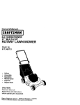
FINDINGMODELNUMBER
This Operator's Manual is an important part of your new lawn tractor. It will help you assemble, prepare and
maintain the unit for best performance. Please read and understand what it says.
Before you start assembling your new equipment, please locate the model plate on the
equipment and copy the information from it in the space provided below. The information on the
model plate is very important if you need help from our Customer Support Department or an
authorized dealer.
You can locate the model number by looking beneath the seat. A sample model plate is explained below. For
future reference, please copy the model number and the serial number of the equipment in the space below.
o
Copy the model number here:
www.bolens.com
•
P. O. BOX LTH61181
TRO¥-BI
LLC
CLEVELAN[_, OH 4413fi
Copy the serial number
here:
33[1-558-7220
866-840_6483
ENGINEINFORMATION
The engine manufacturer is responsible for all engine-related issues with regards to performance, power-rating,
specifications, warranty and service. Please refer to the engine manufacturer's Owner's/Operator's Manual packed
separately with your unit for more information.
CALLINGCUSTOMER
SUPPORT
If you have difficulty assembling this product or have any questions regarding the controls, operation or
maintenance of this unit, please call the Customer Support Department.
Call 1- (330) 558-'7220 or 1- (866) 840-6483 to reach a Customer Support representative. Please
have your unit's model number and serial number readywhen you call. See previous section to locate
this information. You will be asked to enter the serial number in order to process your call.
SECTION1: IMPORTANT
SAFEOPERATION
PRACTICES
WARNING:
This symbol points out important safety instructions which, if not followed, could endanger
the personal safely and/or properly of yourself and others. Read and follow alt instructions in this manuat
before attempting to operate this machine. Failure to comply with these instructions may result in personal
injury. When you see this symbo!--heed its warning.
DANGER:
This machine was buitt to be operated according to the rules for safe operation in this manual. As with any type of power equipment, carelessness or error on the part of the operator can result in
serious injury. This machine is capable of amputating hands and feet and throwing objects. Failure to
observe the following safety instructions could result in serious injury or death.
_lb
or
emit chemicals
to the
Stateof of
cancervehicle
and birth
defects
WARNING:
Engineknown
exhaust,
some
its California
constituents,to cause
and certain
components
reproductive harm,
GENERAL
1.
2.
3.
4.
5.
6.
7.
8.
9.
OPERATION
Read, understand, and follow all instructions on the
machine and in the manua!(s) before attempting to
assemble and operate. Keep this manual in a safe
place for future and regular reference and for
ordering replacement parts.
Be familiar with all controls and their proper
operation. Know how to stop the machine and
disengage them quickly.
Never allow children under 14 years old to operate
this machine. Children 14 years old and over
should read and understand the operation
instructions and safety rules in this manual and
should be trained and supervised by a parent.
Never allow adults to operate this machine without
proper instruction.
To help avoid blade contact or a thrown object
injury, keep bystanders, helpers, children and pets
at least 75 feet from the machine while it is in
operation. Stop machine if anyone enters the area.
Thoroughly inspect the area where the equipment
is to be used. Remove all stones, sticks, wire,
bones, toys, and other foreign objects which could
be picked up and thrown bythe blade(s). Thrown
objects can cause serious personal injury.
Plan your mowing pattern to avoid discharge of
material toward roads, sidewalks, bystanders and
the like. Also, avoid discharging material against a
wall or obstruction which may cause discharged
material to ricochet back toward the operator.
Always wear safely glasses or safety goggles
during operation and while performing an
adjustment or repair to protect your eyes. Thrown
objects which ricochet can cause serious injury to
the eyes.
Wear sturdy, rough-soled work shoes and closefitting slacks and shirts. Loose fitting clothes and
jewelry can be caught in movable parts. Never
operate this machine in bare feet or sandals.
or
other
contain
10. Be aware of the mower and attachment discharge
direction and do not point it at anyone. Do not
operate the mower without the discharge cover or
entire grass catcher in its proper place.
11. Do not put hands or feet near rotating parts or
under the cutting deck. Contact with the blade(s)
can amputate hands and feet.
12. A missing or damaged discharge cover can cause
blade contact or thrown object injuries.
13. Stop the blade(s) when crossing gravel drives,
walks, or roads and while not cutting grass.
14. Watch for traffic when operating near or crossing
roadways. This machine is not intended for use on
any public roadway.
15. Do not operate the machine while under the
influence of alcohol or drugs.
16. Mow only in daylight or good artificial light.
17. Never carry passengers.
18. Disengage blade(s) before shifting into reverse.
Back up slowly. Always look down and behind
before and while backing to avoid a back-over
accident.
19. Slow down before turning. Operate the machine
smoothly. Avoid erratic operation and excessive
speed.
20. Disengage blade(s), set parking brake, stop engine
and wait until the blade(s) come to a complete stop
before removing grass catcher, emptying grass,
unclogging chute, removing any grass or debris, or
making any adjustments.
21. Never leave a running machine unattended.
Always turn off blade(s), place transmission in
neutral, set parking brake, stop engine and remove
key before dismounting.
22. Use extra care when loading or unloading the
machine into a trailer or truck. This unit should not
be driven up or down ramp(s), because the unit
could tip over, causing serious personal injury. The
unit must be pushed manually on ramp(s) to load or
unload properly.
23. Mufflerandenginebecomehotandcancausea
3.
burn. Do not touch.
24. Check overhead clearances carefully before driving
under low hanging tree branches, wires, door
openings etc., where the operator may be struck or
pulled from the unit, which could result in serious
injury.
25. Disengage all attachment clutches, depress the
brake pedal completely and shift into neutral before
attempting to start engine.
26. Your machine is designed to cut normal residential
grass of a height no more than 10 °. Do not attempt
to mow through unusually tall, dry grass (e.g.,
pasture) or piles of dry leaves. Dry grass or leaves
may contact the engine exhaust and/or build up on
the mower deck presenting a potential fire hazard.
27. Use only accessories and attachments approved
for this machine by the machine manufacturer.
Read, understand and follow all instructions
provided with the approved accessory or
attachment.
28. Data indicates that operators, age 60 years and
above, are involved in a large percentage of riding
mower-related injuries. These operators should
evaluate their ability to operate the riding mower
safely enough to protect themselves and others
from serious injury.
29. If situations occur which are not covered in this
manual, use care and good judgment. Contact your
customer service representative for assistance.
4.
5.
6.
7.
1.
2.
3.
4.
5.
OPERATION
Slopes are a major factor related to loss of control and
tip-over accidents which can result in severe injury or
death. All slopes require extra caution. If you cannot
back up the slope or if you feel uneasy on it, do not mow
it.
For your safety, use the slope gauge incIuded as part of
this manual to measure slopes before operating this
unit on a sloped or hilly area. If the slope is greater than
15 degrees as shown on the slope gauge, do not
operate this unit on that area or serious injury could
result.
DO:
1.
2.
Mow up and down slopes, not across. Exercise
extreme caution when changing direction on
slopes.
Watch for holes, ruts, bumps, rocks, or other
hidden objects. Uneven terrain could overturn the
machine. Tall grass can hide obstacles.
wheel weights or counterweights to improve
stability.
Use extra care with grass catchers or other
attachments. These can change the stability of the
machine.
Keep all movement on the slopes slow and gradual.
Do not make sudden changes in speed or direction.
Rapid engagement or braking could cause the front
of the machine to lift and rapidly flip over backwards
which could cause serious injury.
Avoid starting or stopping on a slope. If tires lose
traction, disengage the blade(s) and proceed
slowly straight down the slope.
DO NOT:
6.
SLOPE
Use slow speed. Choose a tow enough speed
setting so that you will not have to stop or shift while
on the slope. Tires may lose traction on slopes
even though the brakes are functioning properly.
Always keep machine in gear when going down
slopes to take advantage of engine braking action.
Follow the manufacturer's recommendations for
7.
Do not turn on slopes unless necessary; then, turn
slowly and gradually downhill, if possible.
Do not mow near drop-offs, ditches or
embankments. The mower could suddenly turn
over if a wheel is over the edge of a cliff, ditch, or if
an edge caves in.
Do not try to stabilize the machine by putting your
foot on the ground.
Do not use a grass catcher on steep slopes.
Do not mow on wet grass. Reduced traction could
cause sliding.
Do not shift to neutral and coast downhill. Overspeeding may cause the operator to lose control of
the machine resulting in serious injury or death.
Do not tow heavy pull behind attachments (e.g.
loaded dump cart, lawn roller, etc.) on slopes
greater than 5 degrees. When going down hill, the
extra weight tends to push the tractor and may
cause you to loose control. (e.g. tractor may speed
up, braking and steering ability are reduced,
attachment may jack-knife and cause tractor to
overturn).
CHILDREN
1.
Tragic accidents can occur if the operator is not
alert to the presence of children. Children are often
attracted to the machine and the mowing activity.
They do not understand the dangers. Never
assume that children will remain where you last
saw them.
a.
b.
Keep children out of the mowing area and in
watchful care of a responsible adult other
than the operator.
Be alert and turn machine off if a child enters
the area.
c.
Before and while backing, look behind and
down for smalt children.
d.
Never carry children, even with the blade(s)
shut off. They may fall off and be sedousty
injured or interfere with safe machine
operation.
e.
Use extreme care when approaching blind
corners, doorways, shrubs, trees or other
objects that may block your vision of a child
who may run into the machine.
f.
Disengage the cutting blade(s) before
shifting in reverse. The "No-Cut-In Reverse °
feature is a reminder not to cut in reverse and
c.
d.
e.
f.
g.
Never remove gas cap or add fuel while the
engine is hot or running. Allow engine to coo!
at least two minutes before refueling.
h. Never over fill fuel tank. Fill tank to no more
than _/_inch below bottom of filler neck to
allow space for fuel expansion.
i.
Replace gasoline cap and tighten securely.
j.
If gasoline is spilled, wipe it off the engine
and equipment. Move unit to another area.
Wait 5 minutes before starting the engine.
k. To reduce fire hazards, keep machine free of
grass, leaves, or other debris build-up. Clean
up oil or fuel spillage and remove any fuel
soaked debris.
I. Never store the machine or fuel container
inside where there is an open flame, spark or
pilot light as on a water heater, space heater,
furnace, clothes dryer or other gas
appliances.
m. Allow a machine to ceot at least five minutes
to help avoid back over accidents. Do not
defeat it.
.
g.
Keep children away from hot or running
engines. They can suffer burns from a hot
muffler.
h.
Remove keywhen machine is unattended to
prevent unauthorized operation.
Never allow children under 14 years old to operate
the machine. Children 14 years old and over should
read and understand the operation instructions and
safety rules in this manual and should be trained
and supervised by a parent.
TOWING
1.
Tow only with a machine that has a hitch designed
for towing. Do not attach towed equipment except
at the hitch point.
2.
Follow the manufacturers recommendation for
weight limits for towed equipment and towing on
slopes.
Never allow children or others in or on towed
3.
equipment.
4.
On slopes, the weight of the towed equipment may
cause loss of traction and loss of control.
5.
6.
Travel slowly and allow extra distance to stop.
Do not shift to neutraI and coast downhill.
before storing.
GENERAL SERVICE:
1.
2.
SERVICE
SAFE HANDLING OF GASOLINE:
1.
To avoid personal injury or property damage
use extreme care in handting gasoline. Gasoline is
extremely flammable and the vapors are explosive.
Serious personal injury can occur when gasoline is
spitled on yourself or your clothes which can ignite.
Wash your skin and change clothes immediately.
a.
b.
Use only an approved gasoline container.
Never filt containers inside a vehicle or on a
truck or trailer bed with a plastic liner. Always
place containers on the ground away from
your vehicle before filling.
When practical, remove gas-powered
equipment from the truck or trailer and refuel
it on the ground. If this is not possible, then
refuel such equipment on a trailer with a
portable container, rather than from a
gasoline dispenser nozzle.
Keep the nozzle in contact with the rim of the
fuel tank or container opening at atl times
until fueling is complete. Do not use a nozzle
lock-open device.
Extinguish all cigarettes, cigars, pipes and
other sources of ignition.
Never fuel machine indoors.
3.
4.
5.
Never run an engine indoors or in a poorly
ventilated area. Engine exhaust contains carbon
monoxide, an odorless, and deadly gas.
Before cleaning, repairing, or inspecting, make
certain the blade(s) and all moving parts have
stopped. Disconnect the spark plug wire and
ground against the engine to prevent unintended
starting.
Periodically check to make sure the blades come to
complete stop within approximately (5) five
seconds after operating the blade disengagement
control. If the blades do not stop within the this time
frame, your unit should be serviced professionally
by an authorized service dealer.
Check brake operation frequently as it is subjected
to wear during normal operation. Adjust and service
as required.
Check the blade(s) and engine mounting bolts at
frequent intervals for proper tightness. Also,
visually inspect blade(s) for damage (e.g.,
excessive wear, bent, cracked).
Replace
theblade(s)withtheoriginalequipment
manufacturer's
(O.E.M.)blade(s)only,listedinthis
manual."Useofpartswhichdonotmeetthe
originalequipment
specifications
mayleadto
improperperformance
andcompromise
safety!°
6. Mowerbladesare sharp. Wrap the blade or wear
gloves, and use extra caution when servicing them.
Keep all nuts, bolts, and screws tight to be sure the
equipment is in safe working condition.
8. Never tamper with the safety interlock system or
other safety devices. Check their proper operation
regularly.
9. After striking a foreign object, stop the engine,
disconnect the spark plug wire(s) and ground
against the engine. Thoroughly inspect the
machine for any damage. Repair the damage
before starting and operating.
10. Never attempt to make adjustments or repairs to
the machine while the engine is running.
7.
WARNING:
11. Grass catcher components and the discharge
cover are subject to wear and damage which could
expose moving parts or allow objects to be thrown.
For safety protection, frequently check components
and replace immediately with original equipment
manufacturer's (O.E.M.) parts only, listed in this
manual. "Use of parts which do not meet the
original equipment specifications may lead to
improper performance and compromise safety! °
12. Do not change the engine governor settings or
over-speed the engine. The governor controls the
maximum safe operating speed of the engine.
13. Maintain or replace safety and instruction labels, as
necessary.
14. Observe proper disposal laws and regulations for
gas, oil, etc. to protect the environment.
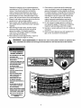
YOUR RESPONSIBILITY- Restrict the use of this power machine to persons who
read, understand and follow the warnings and instructions in this manual and on the machine.
TO AVOID SERIOUS
INJURY OR DEATH
* GOUPAND[t6Wii$LOF_INOTACROSS.
* J_V01D
_I[IDEPl TLIRI_.
*
O0 N[i_t"
0pEp,_TETHEgpjITW[4EREIT
CL_L9 SLIPOF(TIP.
IF MACBINESTOPSGOMGUPHILL,STOP
BLADE_ #]N[IHACKDOWNtIILL_LOWLY.
9LIN_ 510WWiEN CI{ILUK£N
OROTHERS
AREAE{0Un,
NEVER¢_ARY CItlLORE#EVENWITil
8LABE_;
OFF.
LL_K[tOWS1
& BF.MINEI
8EFORE_
WtilLEDAL_ING.
I(FJEP
_AFEtY UEVIL';_S
(GUARU_
SHELOS,
ANn3WtTCH_,ETC.}
IN PLACEANDWOKI(ING.
RF.AIOVE
0BJECT3THATCOULD
BETIS_OWFI
BY THEDLPD_S).
1(SH_W
LOCATI0Pl
_
RJN_:TION0F ALL
COHTROLS.
8E SLIREOLP_}
ANEIF._GtNE
iRE
51"_PPEDBEFOREPLACIS_HAND3
ORFFJET
_EAR BLABE_.
BEFORE
LEAVING_PERATOR'$P0$ITI0Pl_
01$EmGA_
BLAO=-._,
PLACE
THECONtRgL
LEVERIN NELiTRAL,
ENGAGEPARIOHG
BRAKE_
_
READ
_FF ANDRF._I0 VEKEY,
OPERATOR'S
MANUAL
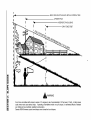
SIGHT AND HOLD THIS LEVEL WITH A VERTICAL TREE
1'4
1,91
A POWER POLE
15°
1.1,1
O,.
0
..I
&i
,_WARNING
Z
0
J
I.1.1.1
Do not mow on inclines with a slope in excess of 15 degrees (a rise of approximately 2-1/2 feet every 10 feet). A riding mower
could overturn and cause serious injury. If operating a walk-behind mower on such a slope, it is extremely difficult to maintain
your footing and you could slip, resulting in serious injury.
Operate RIDING mowers up and down slopes, never across the face of slopes.
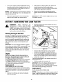
SECTION3: TRACTOR
SET-UP
IMPORTANT:Your tractor is shipped with motor oil in the engine. However, you MUST check the oit level before
starting the engine and operating. Refer to the separate Briggs & Stratton Operator/Owner Manual (or Tecumseh
eng ne s Owner s Manua ) packed w th your tractor. Read nstruct ons carefu y.
NOTE: Reference to right or left hand side of the unit
is observed from the driver's seat, facing forward.
AttachingThe SteeringWheel
°
Tools RequiredFor Assembly
(1) 1/2" socket wrench (for steering wheel)
(1) 9/16" wrench or socket wrench (for seat)
The hardware for attaching the steering wheel has
been packed within the steering wheel, beneath
steering wheel cap. Carefully pry off the steering
wheel cap and remove the hardware.
(2) 7/16" wrenches or socket wrenches (for battery)
NOTE:
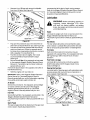
Attachingthe BatteryCables
,
Remove the steering bellow from its packaged
location on the deck engagement!lift lever (found
on the right hand side of tractor). NOTE: Tractor
models 668 & 688 do NOT require a steering bellow
and do NOT come equipped with one.
,
On models so equipped, place the steering bellow
over the steering shaft extending through the dash.
See Figure 2.
NOTE:
There are two different styles of steering
wheel cap. See Figure 2. Styles vary by model.
The positive batter7 terminal is marked Pos.
(+). The negative battery terminal is marked Neg. (-).
°
The positive cable (heavy red wire) is secured to
the positive battery terminal (+) with a hex bolt and
hex nut at the factory. Make certain thai the rubber
boot covers the terminal to help protect it from
corrosion.
,
,
,
Remove the hex bolt and wing nut from the
negative cable.
Remove the black plastic cover, if present, from the
negative battery terminal and attach the negative
cable (heavy black wire) to the negative battery
terminal (-) with the bolt and wing nut.
Make certain the hold-down rod is in position over
the battery, securing it in place. See Figure 1.
W
Rubber
Boot
NOTE:
If the openings on each end of the steering
bellow are two different sizes, the smafler end goes
down, against the dash of the lawn tractor.
With the wheels of the tractor pointing straight
forward, place the steering wheel over the steering
shaft.
Place the washer (with the cupped side down) over
the steering shaft and secure with the hex bolt. See
Figure 2.
Place the steering wheel cap over the center of the
steering wheel and push downward until it "clicks"
into place.
z
Steering
Wheel Cap _
d-
vn
w.ber
Hex Bolt
<
Figure 1
NOTE: If the battery is put into service after the date
shown on top of battery, charge the battery as
instructed on page 24 of this manual prior to operating
the tractor.
Figure 2
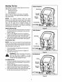
AttachingTheSeat
Standard Adjustment
Seat styles vary by tractor mode! and there are three
different styles available:
•
Standard Adjustment
•
Quick Adjustment &
•
Knob Adjustment
Refer to Figure 3, Figure 4 and Figure 5 to identify
which your tractor's seat style and follow appIicabIe
instructions below.
Hex Screw_
Shoulder
OpenS_i
rr;s
_
NOTE:
For shipping reasons, seats are either
fastened to the tractor seat's pivot bracket with a plastic
tie, or mounted backward to the pivot bracket. In either
case, free the seat form its shipping position and
remove the two hex screws (or knobs, on models so
equipped) from the bottom of seat before proceeding
with applicable instructions below.
StandardAdjustmentSeat
1. Position the shouIder screws (found on the base of
the seat) inside the slot openings in the seat pivot
bracket. Figure 3.
2. Slide the seat slightly rearward in the seat pivot
bracket, lining up the rear slots in the pivot bracket
with the remaining two holes in the seat's base.
3. Select desired position for the seat, and secure with
the two hex screws removed earlier. See Figure 3.
in Slot
Figure 3
Quick Adjustment
)
Seat Stop
\
QuickAdjustmentSeat
NOTE:
ff your seat was shipped mounted backwards
on the seat pivot bracket, pull out the tab found on the
seat stop and hold it open while sliding the seat off the
seat pivot bracket. See Figure 4.
1.
2.
Pivot Bracket
Line up the plastic seat spacers with the slots in
seat pivot bracket.
Slide seat in until front seat spacer engages the
seat stop. See Figure 4.
WARNING:
Before operating this machine,
make sure the seat is engaged in the seat
stop, stand behind the machine and pull back
on seat until fuIly engaged into stop.
Figure 4
KnobAdjustment
Knobs
KnobAdjustmentSeat
1. Position the shoutder screws (found on the base of
the seat) inside the slot openings in the seat pivot
bracket. Figure 5.
2. Slide the seat slightly rearward in the seat pivot
bracket, Iining up the rear slots in the pivot bracket
with the remaining two holes in the seat's base.
3. Select desired position for the seat, and secure with
the two knobs removed earIier. See Figure 5.
Shoulder
Screws
Opening
Figure 5
WARNING:
The shipping brace, used for
packaging purposes only, must be removed
and discarded before operating your riding
mower.
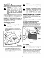
GasandOilFill-up
The gasoline tank is located
under the hood and has a
capacity of either two or three gallons. Do not overfill.
,_
WARNING:
The mowing deck is capable of
throwing objects. Failure to operate the tiding
mower without the discharge cover in the
proper operating position could result in
serious
personal injury and/or properly
damage.
handling gasoline. Gasoline is extremely
WARNING:
extreme arecare
when
flammable and Use
the vapors
explosive.
Never fuel machine indoors or while the
engine
is hot or running.
Extinguish
cigarettes, cigars, pipes, and other sources of
ignition.
Service the engine with gasoline and oil as instructed in
the separate Briggs & Stratton Operator/Owner Manual
(or Tecumseh engine's Owner's Manual) packed with
your tractor. Read instructions carefully.
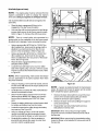
Identifyingthe MulchPlug (if soequipped)
On tractor models with 38- and 42-inch decks so
equipped, a mulch plug can be found within the cutting
deck's discharge opening.
IMPORTANT: Your tractor is shipped with motor oil in the
engine. However, you MUST check the oil level before
operating. Be careful not to overfill.
NOTE:
Refer to Mulchingon page 15 for more detailed
information.
If you'd prefer to operate the cutting deck without
mulching, simply remove the mulch plug by
unthreading the plastic wing nut which fastens it to the
cutting deck. This wilt allow the clippings to discharge
out of the discharge opening during operation. See
Figure 7.
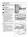
ShippingBraceRemoval
engine
is off, remove
the ignition
key, mower's
and set
WARNING:
Make sure
the tiding
the parking brake before removing the
shipping brace.
o
Locate the shipping brace and accompanying
warning tag found on the right side of the mower,
between the discharge chute and the cutting deck.
See Figure 6.
@
Plastic Wing Nut
Mulch Plug
Figure 7
TirePressure
Warning Tag
Figure 6
o
,_
While holding the discharge chute with your left
hand, remove the shipping brace with your right
hand by grasping it between your thumb and index
finger and rotating it clockwise.
any
circumstances
is 30
Equalunder
tire
WARNING:
Maximum
tire psi.
pressure
pressure should be maintained at all times.
The tires on your unit may be over-inflated for shipping
purposes. Reduce the tire pressure before operating
the tractor. Recommended operating tire pressure is
approximately 10 p.s.i for the rear tires & 14 p.s.i, for
the front tires. Check sidewall of tire for maximum p.s.i.
10
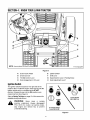
SECTION4: KNOWYOURLAWNTRACTOR
DDDDD_
t If so equipped
Figure 8
A
Clutch-brake Pedal
E
B
C
Choke Control1Throttle Control Lever
F
G
D
Deck Engagement / Lift Lever
H
Ignition Switch
Shift Lever
Speed Control Lever / Parking Brake
Seat Adjustment Lever1-
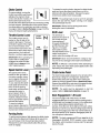
IgnitionSwitch
STOP
The ignition switch is located on the right side of the
tractor's dash .To start the engine, insert the key into the
ignition switch and turn clockwise to the START
position. Release the key into the ON position once
engine has fired. See Figure 9.
RUN
Refer to StartingThe Engineon page 13 of this manual for
detailed starting instructions.
Tractor Models
START
668 & 688 Only
6
machine unattended.
WARNING:
Never Always
leave disengaged
a running
PTO, Shift into neutral, set parking brake,
stop engine and remove key to prevent
unintended starting.
All Tractor Models
Except 668 & 688
Figure 9
11
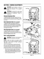
ChokeControl
To release the parking brake, depress the clutch-brake
pedal and move the speed control lever out of the
notches to the desired position. Release the speed
control lever and the clutch-brake pedal.
On some models, moving the
throttle lever all the way forward
activates the engine's choke
control. On all other models, the
choke control can be found on
NOTE:
The parking brake must be set if the operator
leaves the seat with the engine running or the engine
wit/automatically shut off.
the left side of the dash panel and is activated by pulling
the knob outward. Activating the choke control closes
the choke plate on the carburetor and aids in starting
the engine. Refer to StartingTheEngineon page 13 of this
manual for detailed starting instructions.
Throttle ControlLever
The throttle control lever is
located on the left side of the
tractor's dash panel. This lever
controls the speed of the engine
and, on some models, when
pushed all the way forward, the
choke control also. When set in a
IMPORTANT:Always set the parking brake when
leaving the tractor unattended.
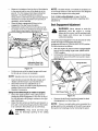
ShiftLever
The shift lever is
located in the center of
the console and has
c.o.oI'q
Position
three positions, F
(Forward), N (Neutral)
Fast
Position
and R (Reverse). See
Figure 8. The clutchbrake pedal must be
fully depressed and the
tractor must not be in
(_
given position, the throttle witt
maintain a uniform engine speed.
IMPORTANT: When operating the
tractor with the cutting deck
engaged, be certain that the
throttle lever is always in the
FAST (rabbit) position.
R
Shift
Knob
motion when the moving shift lever.
IMPORTANT: Never force the shift lever. Doing so may
result in serious damage to the tractor's transmission.
NOTE:
/f difficulty is encountered while attempting to
shift, release the clutch-brake pedal slightly before fully
depressing the pedal again.
Slow
Position (_
SpeedControlLever
The speed control tever,
located on the right side of
the center console, allows
you to regulate the ground
speed of the lawn tractor.
To use, depress the clutchbrake pedal and move the
lever out of the parking
brake notch and forward to
increase the tractor's
N
Clutch-brakePedal
6
I5
The clutch-brake pedal is located on the left side of the
lawn tractor, along the running board. Depress the
clutch-brake pedal part way down when slowing the
tractor by changing speeds (Refer to ;SpeedControlLever).
Depress the pedal all the way down to engage the disc
brake and bring the tractor to a complete stop.
NOTE:
The pedal must be depressed to start the
engine. Refer to SafetyInterlockSwitcheson page 13.
ground speed. When a
desired speed has been
reached, release the lever
into an appropriate notch to
maintain that speed.
To slow the tractor's
ground speed, depress the _+Speed
Mode+
Showr
clutch-brake pedal and move the speed control lever
rearward and release it into a notch.
DeckEngagement/LiftLever
Found on the right side of the tractor, the deck
engagement/lift lever is used to set the mowing deck's
cutting height and engage the power to the cutting deck
or other (separately available) attachments. To
operate, move the lever to the right and forward, before
placing it a notch for your desired cutting height. Moving
the lever to the right and alt the way rearward placing it
into the BLADES STOP position disengages power to
the cutting deck/attachment.
ParkingBrake
To set the parking brake, fully depress the clutch-brake
pedat. Move the speed control lever all the way to the
rear and release it into the parking brake position.
Release the clutch-brake pedal to allow the parking
brake to engage.
NOTE:
The deck engagement/lift lever must be in the
disengaged (BLADES STOP) position when starting
the engine, when traveling in reverse and if the operator
leaves the seat.
12
SECTION5: OPERATING
THELAWNTRACTOR
Startingthe Engine
WARNING
AVOIDSERIOUS
INJURYORDEATH
NOTE: Refer to the TRACTORSET-UPon page 8 of this
• {F MACHINE STOPS GOING UPHILL, STOP BLADE(S) AND
BACK DOWNHILL SLOWLY.
• DO NOT MOW WHEN
CHILDREN
OR OTHERS
ARE
AROUND.
• NEVER CARRY CHILDREN, EVEN W{TH BLADES OPE
• LOOK DOWN AND BEHIND BEFORE AND WHILE BACKING.
manual for Gasoline and Oit fill-up instructions.
,
,
,
,
• KEEP
SAFETY
DEVICES
(GUARDS,
SHIELDS,
AND
SWITCHES) IN PLACE AND WORKING.
• REMOVE OBJECTS THAT COULD BE THROWN BY THE
,
BLADE(S).
• KNOW LOCATION AND FUNCTION OF ALL CONTROLS.
• BE SURE BLADE(S) AND ENGINE ARE STOPPED BEFORE
PLACING HANDS OR FEET NEAR BLADE(S).
• BEFORE LEAVING OPERATORS
POSITION,
D{SENGAGE
,
READOPERATOR'S
MANUAL
NOTE:
all
instructions and
warnings
on theand
machine
WARNING:
Read,
understand,
follow
and in this manual before operating.
IfStartingproblemsareencountered,
TROUBLE
SHOOTING
GUIDEon page 28.
WARNING:
If you strike a foreign object,
stop the engine, disconnect the spark plug
wire(s) and ground against the engine.
Thoroughly inspect the machine for any
damage. Repair the damage before restarting
and operating
,
,
,
,
,
BeforeStartingEngine
,_
referto
Stoppingthe Engine
The engine will automatically shut off if the operator
leaves the seat before engaging the parking brake.
The engine will automatically shut off if the operator
leaves the tractor's seat with the deck engagement/
lift lever in ANY position other than BLADES STOP.
The engine will automatically shut off if the deck
engagement/lift lever is moved out of the BLADES
STOP position with the shift lever in R (reverse).
,
After the engine starts, deactivate the choke control
and place the throttle control in the FAST position.
operating the tractor. Doing so wilt result in a "rich" fuel
mixture and cause the engine to run poorly.
This tractor is equipped with a safety interlock system
for the protection of the operator. If the interlock system
should ever malfunction, do not operate the tractor.
Contact an authorized service dealer. The safety
interlock system prevents the engine from cranking or
starting unless the parking brake is engaged, and the
deck engagement/lift lever is in the disengaged
(BLADES STOP) position.
,
Turn the ignition key clockwise to the START
position. After the engine starts, release the key. It
wilt return to the ON position.
IMPORTANT: Do NOT leave the choke control on while
SafetyInterlockSystem
,
Insert the tractor key into the ignition switch.
Place the deck engagement/lift lever in the
BLADES STOP position.
Engage the tractor's parking brake.
Activate the choke control.
IMPORTANT: Do NOT hold the key in the START
position for longer than ten seconds at a time. Doing so
may cause damage to your engine's electric starter.
BLADE(S), PLACE THE SHIFT LEVER IN NEUTRAL, ENGAGE
PARKING BRAKE, SHUT ENGINE OFF AND REMOVE KEY.
,_
interlock system
is operate
malfunctioning,
WARNING:
Do not
the tractor ifThis
the
system was designed for your safety and
protection,
,_
• GO UP AND DOWN SLOPES, NOT ACROSS.
• AVOID SUDDEN TURNS.
• DO NOT OPERATE THE UNIT WHERE {T COULD SLIP OR
TIR
all
instructions and
warnings
on theand
machine
WARNING:
Read,
understand,
follow
and in this manual before operating.
13
If the blades are engaged, place the deck
engagement/lift lever in the BLADES STOP
position.
Depress the clutch-brake pedal to bring the tractor
to a complete stop.
Turn the ignition key counterclockwise to the OFF
position.
Engage the tractor's parking brake.
Remove the key from the ignition switch to prevent
unintended starting.
°
°
°
°
°
°
Operating
TheLawnTractor
before
and while
backing
up to avoid
backWARNING:
Always
Iookdown
and abehind
over accident.
,_
WARNING:
Before leaving the operator's
position. Always place the deck engagement!
lift lever in the BLADES STOP position, shift
into neutral, set parking brake, stop engine
and remove key to prevent unintended
starting.
°
Restart engine.
Place speed control lever in high speed position.
Release clutch-brake pedal fully.
Depress clutch-brake pedal.
Place speed control lever in desired position.
Place shift lever in either FORWARD or REVERSE,
and follow normal operating procedures.
EngagingTheCuttingBlades
WARNING:
Keep feet and hands away
from the discharge opening, the blades or
any part of the deck. When the unit is used
for anything other than mowing operations,
the blade drive should be disengaged.
Move throttle control lever to full throttle.
NOTE:
Always operate the tractor with the throttle
control lever in the FAST (rabbit) position for the most
efficient use of the cutting deck or other (separately
available) attachments.
°
°
To engage power to the cutting deck or other
(separately available) attachment, proceed as follows:
°
Place the shift lever in either the FORWARD or
REVERSE position.
Release the parking brake by depressing the
clutch-brake pedal and positioning the speed
control lever in desired position.
°
°
IMPORTANT: First-time operators should use speed
positions 1 or 2. Become completely familiar with the
tractor's operation and controls before operating the
tractor in higher speed positions.
°
Release clutch-brake pedal slowly to put unit into
motion.
°
The lawn tractor is brought to a stop by depressing
the clutch-brake pedal.
NOTE:
NOTE:
Mowing
When operating the unit initially, there will be
WARNING:
To help avoid blade contact or
a thrown object injury, keep bystanders,
helpers, children and pets at least 75 feet
from the machine while it is in operation. Stop
machine if anyone enters the area.
position for any
reason,
the
WARNING:
Before
leaving disengage
the operator's
blades, place the shift lever in neutral,
engage the parking brake, shut engine off
and remove the key.
The following information will be helpful when using the
cutting deck with your tractor.
WARNING:
Plan your mowing pattern to
avoid discharge of materials toward roads,
sidewalks, bystanders and the like. Also,
avoid discharging material against a wall or
obstruction which may cause discharged
material to ricochet back toward the operator.
IMPORTANT: When stopping the tractor for any reason
while on a grass surface, always
•
,,
•
Place the shift lever in neutral,
Engage the parking brake,
Shut engine off and remove the key.
.
Doing so will minimize the possibility of having your
lawn "browned" by hot exhaust from your tractor's
running engine.
°
If unit stalls with speed control in high speed, or if unit
wilt not operate with speed control lever in a low speed
position, proceed as follows.
°
The deck engagement/lift lever must be in the
disengaged (BLADES STOP) position when starting
the engine, when traveling in reverse and if the operator
leaves the seat. Refer to SafetyInterlock Switcheson page
13
little difference between the highest two speeds until
after the belts have seated themselves into the pulleys
during the break-in period.
,_
Move the deck engagement!lift lever to the right
and forward,
Place the lever a notch for your desired cutting
height.
Moving the lever to the right and all the way
rearward placing it into the BLADES STOP position
raises and disengages power to the cutting deck.
°
Place shift lever in NEUTRAL.
14
Be sure that the lawn is clear of stones, sticks, wire,
or other objects which could damage lawn mower
or engine.
For best results and to insure more even grass
distribution, do not mow when lawn is excessively
wet.
Do not mow at high ground speed, especially if a
mulch kit or grass collector is installed.
.
.
.
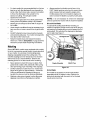
For best results it is recommended that the first two
Always position the throttle control lever in the
FAST (rabbit) position and allow it to remain there
while mowing. Failing to keep the engine at full
throttle places strain on the tractor's engine and
does not aItow the blades to properly mulch grass.
laps be cut with the discharge thrown towards the
center. After the first two laps, reverse the direction
to throw the discharge to the outside for the
balance of cutting. This will give a better
appearance to the lawn.
Do not cut the grass too short. Short grass invites
weed growth and yellows quickly in dry weather.
Mowing shouId always be done with the engine at
full throttle.
.
Under heavier conditions it may be necessary to go
back over the cut area a second time to get a clean
cut.
.
Do NOT attempt to mow heavy brush and weeds
and extremely tail grass. Your tractor is designed to
mow lawns, NOT clear brush.
,
Keep the blades sharp and replace the blades
when worn. Refer to CuttingBladeson page 23 of this
manual for proper bIade sharpening instructions.
NOTE:
It is not necessary to remove the discharge
chute to operate the mower with the mulch kit installed.
38- and 42-inch Decks
To operate the cutting deck without mulching, on
models so equipped, simply remove the mulch plug by
unthreading the plastic wing nut which fastens it to the
cutting deck. This wilt allow the clippings to discharge
out the side. See Figure 7.
Mulching
Some, NOT ALL, models come equipped with a mulch
kit which incorporates special blades, already standard
on your tractor, in a process of recircuIating grass
clippings repeatedly beneath the cutting deck. The
ultra-fine clippings are then forced back into the lawn
where they act as a natural fertilizer. Observe the
following points for the best results when mulching.
.
Never attempt to mulch if the lawn is damp. Wet
grass tends to stick to the underside of the cutting
deck preventing proper mulching of the clippings.
.
Do NOT attempt to mulch more than 1/3 the total
height of the grass or approximately 1-1/2 inches.
Doing so will cause the clippings to clump up
beneath the deck and not be mulched effectively.
Maintain a slow ground speed to allow the grass
clippings more time to effectively be mulched.
.
@
Plastic Wing Nut
Mulch Plug
Figure 10
46-inch Decks
On models so equipped, the mulch kit is packed
separately within the tractor's crate. Observe the
instructions included with the mulch kit for the best
results when mulching.
15
SECTION6: MAKINGADJUSTMENTS
_lb
adjustments
while
engine to ismake
running,
WARNING:
Nevertheattempt
any
except where specified in the operator's
manual.
Hex Screws
wire(s)
and ground
against the
WARNING:
Disconnect
theengine
sparkbefore
plug
performing
any adjustments,
repairs or
maintenance.
StandardAdjustmentSeat
To adjust the position of the seat, loosen the two hex
screws on the bottom of the seat. See Figure 11. Slide
the seat forward or backward as desired. Retighten the
two screws.
QuickAdjustmentSeat (if soequipped)
Figure 11
To adjust the position of the seat on models so
equipped, move the seat adjustment lever (located
under the seat) to the left and slide the seat forward or
backwards. See Figure 12. Make sure seat is locked
into one of the six adjustment positions before
operating the lawn tractor.
Seat
Adjustment
Lever
KnobAdjustmentSeat (if soequipped)
To adjust the position of the seat on models so
equipped, loosen the two knobs on the bottom of the
seat. See Figure 13. Slide the seat forward or backward
as desired. Retighten the two knobs.
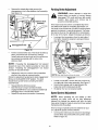
DeckLevelingAdjustment
(3
,_
WARNING:
heavy
gloves toProtect
grasp the
yourcutting
handsblade.
by wearing
Figure 12
NOTE: Check the tractor's tire pressure before
performing any deck leveling adjustments. Refer to
Tires later in this section for further information
Knobs
regarding tire pressure.
The front of the cutting deck is supported by two lift
links, one of which can be adjusted to level the deck
from both front to rear & side to side. The front of the
deck should be between 1/4-inch and 3/8-inch lower
than the rear of the deck. Adjust if necessary as follows:
o
o
With the tractor parked on a firm, level surface,
place the deck engagement!lilt lever in the top
cutting height notch (not BLADES STOP) position.
Rotate the blade nearest the discharge chute so
that it is parallel with the tractor.
Figure 13
16
°
°
°
Measure the distance from the front of the blade tip
to the ground and the rear of the blade tip to the
ground. The first measurement taken should be
between 1/4" and 3/8" less than the second
NOTE: The deck wheels, on models so equipped, are
measu rement. Determine the approximate distance
necessary for proper adjustment and proceed, if
necessary, to the next step.
Place the deck engagement/lift lever in the
engaged (all the way forward) position.
Remove the hairpin clip from the ferrule found at
the bottom of the front, left deck link (hairpin clip is
on the inside of the lift link). See Figure 14.
Refer to DeckLevelingAdjustment
on page 16 of this
manual for more detailed instructions regarding deck
adjustments.
an anti-scalp feature of the deck and are not designed
to support the weight of the cutting deck.
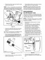
DeckEngagement
Adjustment
WARNING:
Never attempt to make the
adjustment while the engine is running.
Always shift to neutral, set the parking brake,
stop engine and remove key to prevent
unintended s_arting.
O
The cutting deck engagement may be adjusted to make
certain the deck is disengaged when deck
engagement/lift lever is in the BLADES STOP position.
Correct adjustment as follows.
.
.
With the engine off, place the deck engagement/lift
lever in the top cutting height notch (not BLADES
STOP) position.
Unthread the shift knob and remove the two flange
screws which secure the shift cover panel in place.
See Figure 15.
Adjustable Deck Link,
Ferrule & Hairpin Clip
Flange Screws
Figure 14
,
Pull the ferrule out of the deck hanger and thread
the ferrule up or down, as necessary.
NOTE: Usually only one ortwo turns are needed.
.
°
°
Insert the ferrule back into the deck hanger and
refasten with the hairpin clip removed earlier.
Checkthe front-to-rear adjustment by remeasuring. Check the side-to-side adjustment by
placing a level on the deck surface.
Readjust if necessary.
Shift Knob
Shift Cover Panel
Settingthe OeckWheel Height (on models soequipped)
,
°
,_
Select the height position of the cutting deck by
placing the Deck Engagement / Lift Lever in any of
the five different cutting height notches on the right
side of the frame.
Adjust the deck wheels so that they are between _,_.inch and _!_-inchabove the ground when the tractor
is on a smooth, flat surface such as a driveway.
from
the discharge
of the
WARNING:
Keep opening
hands and
feet cutting
away
deck.
17
Figure 15
,
Remove the shift cover panel and locate the deck
disengagement rod. See Figure 16.
NOTE:
There is a small yellow wire connected to a
spring switch on the underside of the shift cover panel.
Be careful not to damage it when removing the panel.
Remove the hairpin clip which secures the
disengagement rod to the stabilizer shaft assembly.
See Figure 16.
o
ParkingBrakeAdjustment
,i_
•
_
._
"_JIl_l
WARNING:
Never attempt to adjust the
disengage PTO, move shift lever into neutral
position,
stop the
engine
remove Always
key to
brakes while
engineand
is running.
prevent unintended starting.
o
Stabilizer Shaft
I_1
/ /""_/////
_
Assembly
_
.
Looking at the transmission from the right side of
the tractor, locate the extension spring and brake
Disengagement Rod
Extension
Spring
Figure 16
o
o
Hex Nut
Pult the rod toward the rear of the tractor (to take up
slack), then thread the rod inward or outward
(usually only one or two turns) untit the rod lines up
as precisely as possible with the hole in the
stabilizer shall.
NOTE:
Threading the disengagement rod outward
(toward the rear of the tractor) provides for more belt
tension. Threading the disengagement
rod inward
provides for less belt tension.
Transmission
o
Reinsert the rod and re-secure it to the stabilizer
shaft with the cotter pin removed earlier.
Check the adjustment by placing the deck engagement/
lift lever in the BLADES STOP position. The deck
should move up and forward, allowing the belt to
become loose.
o
o
o
NOTE:
Rear, right wheel not shown for elarib]
Figure 17
o
o
Reassemble the shift cover panel.
Start the tractor's engine and test the deck
engagement/lift lever to be certain the blades fuIly
disengage when in the BLADES STOP.
Repeat the adjustment procedure if necessary.
o
Loosen, but do NOT remove, the he:<nut found on
the right side of the brake assembly. See Figure 17.
Using a feeler gauge, set the gap between the
brake disc and the brake puck at .011 ".
Re-tighten the hex nut loosened earlier.
SpeedControlAdjustment
NOTE:
When operating the unit initially or after
replacing the belts, there wilt be little difference
between the highest two speeds until after the belts
have gone through a break-in period and have seated
themselves into the pulleys.
If the full range of speeds cannot be obtained on your
unit, adjust the speed control as follows.
o
18
Unthread the shift knob and remove the two flange
screws which secure the shift cover panel in place.
Refer to Figure 15.
°
Remove
theshiftcoverpanelandlocatethespeed
controlrod.SeeFigure18.
°
Reassemble the shirt cover panel, start the tractor's
engine and test the futt range of speeds.
IMPORTANT: If the above adjustment did not result in
the tractor obtaining the full range of speeds, see an
authorized service dealer to have the variable speed
drive system inspected and professionally adjusted.
NOTE:
There is a small yellow wire connected to a
spring switch on the underside of the shift cover panel.
Be careful not to damage it when removing the panel.
Ferrule and
Hairpin Clip
SteeringAdjustment
(UnitsWithAdjustableTie Rod)
If the tractor turns tighter in one direction than the other,
or if either the tie rod and ferrule are being replaced due
to damage or wear, the tie rod may need to be adjusted.
To do so, proceed as follows:
NOTE: A replacement cotter pin (part no. 714-0470)
is needed to complete this adjustment.
hand before proceeding.
,
Place the steering wheel in position for straight
ahead travel.
,
In front of the pivot bar, measure the distance
horizontally from the inside of the left rim to the
inside of the right rim. Note the distance.
Figure 18
,
Remove the hairpin clip which secures the speed
control rod's ferrule to the speed bracket. See
Figure 18.
Behind the pivot bar, measure the distance
horizontally from the inside of the left rim to the
inside of the right rim. Note the distance.
,
The measurement taken in front of the pivot bar
should be between 1/16° and 5/16" less than the
Speed Control Rod
°
At the factory, the speed control rod is adjusted so that
5/8-in. of the rod is exposed beyond the ferrule.
°
Have one on
measurement taken behind the pivot bar. If it is not,
an adjustment is necessary. Proceed as follows.
,
Adjust the speed control by threading the ferrule
inward so that no more than 3t4-in. of the rod is
exposed beyond the ferrule. See Figure 19.
Locate the ferrule at the right end of the tie rod, just
to the rear of the right, front tire of tractor. See
Figure 20.
Flat Washe
Tie Rod
Right Axle
Right Front Tire
NOTE:
Fgure is NOT to scale
Figure 20
Figure 19
,
Remove the cotter pin and fiat washer which
secures the adjustment ferrule to the tractors right
axle.
Reinsert the ferrute and re-secure the rod with the
cotter pin removed earlier.
19
Two turns at a time, thread the adjustment ferrule
toward the right, front tire to lengthen the tie rod. Or,
thread the adjustment ferrule away from the right,
front tire to shorten the tie rod.
°
Make certain the steering wheel is in position for
straight-ahead travel before again taking
measurements. Continue to repeat the steps above
until a proper adjustment is achieved.
NOTE: Lengthening the tie rod increases the tractor's
°
Secure the tie rod to the right axle with the flat
washer removed earlier and a replacement cotter
pin.
o
front tie toeqn. Shortening
tractor's front tire toeqn.
.
the tie rod decreases
the
Reinsert the adjustment ferrule and temporarily
secure it with the cotter pin removed earlier.
IMPORTANT: Do NOT reuse the original cotter pin once
it has been removed.
SECTION7: MAINTAINING
YOURLAWNTRACTOR
.
WARNING:
Before
performing
any
maintenance
or repairs, place the deck
engagement/lift lever in the BLADES STOP
position, move shif_ lever into neutral position,
set parking brake, stop engine and remove
key to prevent unintended starting.
Snap the small end of oil drain sleeve onto the oit
sump. See Figure 21.
CleaningtheEngineAndDeck
Any fuel or oil spilled on the machine should be wiped
off promptly. Do NOT allow debris to accumulate
around the cooling fins of the engine or on any other
part of the machine, especially the belts, pulleys and
other moving parts. Clean the underside of the deck
with a wisk broom, scraper or forced air after each
mowing.
IMPORTANT: The use of a pressure washer or garden
hose to clean your tractor is NOT recommended. It may
cause damage to electrical components, spindles,
pulleys, bearings or the engine. The use of water will
result in a shortened life of the tractor and reduce its
Oil Drain Sleeve
Figure 21
.
Remove drain plug and drain oil into a suitable
container with a capacity of no less than 64 oz.
.
Service the oil filter (if so equipped) as instructed
in the separate Briggs & Stratton Operator/Owner
Manual (or Tecumseh engine's Owner's Manual)
packed with your unit.
Perform the above steps in the opposite order after oil
has finished draining.
serviceability.
Engine
Refer to the Briggs & Stratton OperatodOwner
Manual (or Tecumseh engine's Owner's Manual)
for engine maintenance instructions.
Check engine oil level before each use as instructed in
the Briggs & Stratton Operator/Owner Manual (or
Tecumseh engine's Owner's Manual) packed with your
unit. Fellow the instructions carefully.
.
IMPORTANT: Refer to the Briggs & Stratton Operator/
Owner Manual (or Tecumseh engine's Owner's
Manual) packed with your unit for information regarding
the quantity and proper weight of motor oil.
ChangingEngineOil
(modelsequippedwith an oil drain sleeve)
For draining oil from the engine's crankcase of select
modei tractors, a plastic oil drain sleeve is packed with
this Operator's Manual. To drain the oil, proceed as
follows:
°
Refill the engine with new motor oil.
ChangingEngineOil
(modelsequippedwith an oil drain valve)
NOTE:
Depending on your tractor's engine make &
model, it may be necessary to remove the tractor's side
panel in order to replace the oil filter (if so equipped).
Unscrew the oit fill cap and remove the dipstick
from the oil fitt tube.
20
o
Unscrew the oil fill cap and remove the dipstick
from the oil fill tube. See Figure 22.
recommended at the start of each mowing season.
Refer to the Briggs & Stratton Operator/Owner ManuaI
(or Tecumseh engine's Owner's Manual) for correct
plug type and gap specifications.
Lubrication
WARNING:
inspecting,
shift lever
brake, stop
unintended
Before lubricating, repairing, or
always disengage PTO, move
into neutral position, set parking
engine and remove keyto prevent
starting.
Engine
Lubricate the engine with motor oil as instructed in the
Bt_ggs & Stratton Operator/Owner Manual (or
Tecumseh engine's Owner's Manual) packed with your
unit.
Drain Port
Figure 22
Rear Wheels
The rear wheels should be removed from the axles
once a season. Lubricate the axles and the rims well
.
Pop open the protective cap on the end of the oil
drain valve to expose the drain port. See Figure 22.
.
Push the oil drain hose (packed with this manual)
onto the oil drain port. Route the opposite end of
the hose into an appropriate oil collection container
with a capacity of no less than 64 oz.
.
Push the oil drain valve in slightly, then rotate
counterclockwise and pull outward to begin
draining oil.
.
Service the oil filter (if so equipped) as instructed
in the separate Briggs & Stratton Operator/Owner
Manual (or Tecumseh engine's Owner's Manual)
packed with your unit.
Perform the above steps in the opposite order after oil
has finished draining.
.
with an all-purpose grease before re-installing them.
FrontAxles
Each end of the tractor's front pivot bar may be
equipped with a grease fitting. If so equipped, lubricate
with a grease gun after every 25 hours of tractor
operation.
Pivot Points& Linkage
Lubricate all the pivot points on the drive system,
clutch-brake pedal and lif_linkage at least once a
season with light oil.
SteeringShaft and Gear
Lubricate teeth of steering gears with automotive multipurpose grease after every 25 hours of operation or
once a season. See Figure 23.
Refill the engine with new motor oit.
IMPORTANT: Refer to the Briggs & Stratton Operator/
Owner Manual (or Tecumseh engine's Owner's
Manual) packed with your unit for information regarding
the quantity and proper weight of motor oil.
Air Cleaner
Service the pre-cIeaner, if so equipped, and cartridge/
air cleaner element as instructed in the Briggs &
Stratton Operator/Owner Manual (or Tecumseh
engine's Owner's Manual) packed with your unit.
Fuel Filter
0
.
_
0
0
0
Service the fuel filter, ifso equipped, as instructed in the
Bt_ggs & Stratton Operator/Owner Manual (or
Tecumseh engine's Owner's Manual) packed with your
unit.
Steering Shm_tand Gear
Spark Plug(s)
The spark plug(s) should be cleaned and the gap reset
once a season. Spark plug replacement is
Figure 23
21
SECTION8: SERVICE
_
and
ground Disconnect
against the
before
WARNING:
the engine
spark plug
wire
performing
any adjustments,
repairs or
maintenance.
Hook
CuttingDeckRemoval
WARNING:
Shut the engine off, remove
ignition key, set the parking brake, disconnect
the spark plug wire(s) and ground against the
engine to prevent unintended starting before
removing the cutting deck.
_bb
safety
goggles Always
to protect
while
WARNING:
wear your
safety eyes
glasses
or
removing the cutting deck.
Transmission
Spring
For performing service on your tractor and in order to
properly mount some (separately available)
attachments, it may be necessary to remove the
tractor's cutting deck. To due so, proceed as follows:
o
o
o
o
Figure 24
Place the deck engagement/lift lever in the
engaged (all the way forward) position.
Using a spring puller (MTD Part No. 732-0571)or
other suitable tool, disconnect the spring which is
attached to a small hook found on the left, rear
portion of the transmission. See Figure 24.
Place the deck engagement/lift lever in the
BLADES STOP position.
Locate the two belt keeper pins, found on either
side of the engine pulley, and use a 1/4-inch socket
wrench to remove them from the lower frame. See
Belt Keeper Pins
Figure 25.
pins are assembled in the same locations from which
they were removed.
o
o
o
o
Deck Belt
Deck Anti-sway Rod
NOTE: When reassembling, make certain beft keeper
Figure 25
,)
Unpile the deck belt from around the engine
pulley.Return the deck engagement/lift lever to the
engaged (all the way forward) position.
Locate the deck anti-sway rod and adjustable deck
links found near the front of the cutting deck. See
Figure 25 & Figure 26.
First remove the hairpin clip which secures the antisway rod to the front portion of the cutting deck,
then remove the hairpin clips which secure the
adjustable deck hangers. Retain the hairpin clips.
Carefully lower the front portion of the deck to the
ground.
0
Adjustable Deck Links
Figure 26
22
Deck Anti-sway Rod
and Hairpin Clip
o
Remove the hairpin clips which secure the rear
deck hangers to the deck stabilizer bracket. See
Figure 27. Retain the hairpin clips.
The blades may be removed as follows.
°
Rear Deck Hangers
°
Remove the deck from beneath the tractor, (refer to
CuttingDeckRemoval
on page 22) then gently flip the
deck over to expose its underside.
Place a block of wood between the center deck
housing baffle and the cutting blade to act as a
s_abilizer. See Figure 28.
Hex Flange Nut
Stabilizer Bracket
Figure 27
.
Carefully lower the rear portion of the deck to the
ground.
Spindle Assembly
NOTE:
For normal service and maintenance, the
deck stabilizer bracket doesn't need to be removed
from the tractor, ff removing the cutting deck in order to
mount a Snow Thrower attachment, however, the
stabilizer bracket must be removed. To do so, simply
remove the hairpin clip which secures the stabilizer rod
to the stabilizer bracket. See Figure 27.
°
°
Figure 28
.
Use a 15/16" wrench to remove the
that secures the blade to the spindle
Figure 28.
To properly sharpen the cutting blades,
amounts of metal from both ends of the
the cutting edges, parallel to the trailing
to 30 ° angle. See Figure 29.
Place the deck engagement/lift lever in the
BLADES STOP position to raise the lift links up,
and out of the way.
Carefully slide the deck from beneath the right side
of the lawn tractor.
hex flange nut
assembly. See
remove equal
blades along
edge, at a 25 °
Blade Separation
!
CuttingBlades
WARNING:
Be sure to shut the engine off,
remove ignition key, disconnect the spark
plug wire(s) and ground against the engine to
prevent unintended starting before removing
the cutting blade(s) for sharpening
or
replacement, Protect your hands by using
heavy gloves or a rag to grasp the cutting
blade,
Worn Blade Edge
Wind Wing
WARNING:
Periodically inspect the blade
adapter and/or spindle for cracks or damage,
especially if you strike a foreign object,
Replace immediately if damaged.
Sharpen Edge Evenly
Figure 29
IMPORTANT: If the cutting edge of the blade has already
been sharpened to within 5/8" of the wind wing radius,
or if any metal separation is present, replace the blades
with new ones. See Figure 29.
23
Itis important
thateachcuttingbladeedgebeground
equallytomaintainproperbladebalance.A poorly
balancedbladewillcauseexcessive
vibrationandmay
causedamagetothetractorandresultinpersonal
injury.
Thebladecanbetestedbybalancing
it ona round
IMPORTANT: Never jump your tractor's dead battery
with the battery of a running vehicle.
°
°
shaft screwdriver. Grind metal from the heavy side until
it balances evenly.
When replacing the blade, be sure to insta!l the blade
with the side of the blade marked "Bottom" (or with a
part number stamped in it) facing the ground when the
mower is in the operating position.
,_
Clean the battery by removing it from the tractor and
washing with a baking soda and water solution. If
necessary, scrape the battery terminals with a wire
brush to remove deposits. Coat terminals and exposed
wiring with grease or petroleum jelly to prevent
corrosion.
Battery
°
°
°
Acid
Battery Failures
Always keep the battery cables and terminals clean
and free of corrosive build-up.
After cleaning the battery and terminals, apply a
light coat of petroleum jelly or grease to both
terminals
Some common causes for battery failure are:
• incorrect initial activation
• undercharging
• overcharging
• corroded connections
• freezing
These failures are NOT covered by your tractor's
warranty.
Always keep the rubber boot positioned over the
positive terminaI to prevent shorting.
Tires
IMPORTANT: If removing the battery for any reason,
disconnect the NEGATIVE (Black) wire from it's
terminal first, followed by the POSITIVE (Red) wire.
When re-installing the battery, always connect the
POSITIVE (Red) wire its terminal first, followed by the
NEGATIVE (Black) wire. Be certain that the wires are
connected to the correct terminals; reversing them
could change the polarity and cause damage to your
engine's alternating system.
Recommended operating tire pressure is
approximately 10 p.s.i. Maximum tire pressure under
any circumstances is 30 p.s.i. Equal tire pressure
should be maintained on all tires.
When installing a tire to the rim, be certain rim is clean
and free of rust. Lubricate both the tire and rim
generously. Never inflate to over 30 p.s.i, to seat
beads.
Charging
WARNING:
Excessive pressure (over 30
p.s.i.) when seating beads may cause tire/rim
assembly to burst with force sufficient to
cause serious injury.
If the tractor has not been put into use for an extended
period of time, charge the battery with an automotivetype 12-volt charger for a minimum of one hour at six
amps.
WARNING:
Batteries give off an explosive
gas while charging. Charge battery in a welt
ventilated area and keep away from an open
flame or pilot light as on a water heater, space
heater, furnace, clothes dryer or other gas
appliances.
BeltReplacement
WARNING:
Shut the engine off, remove
ignition key, set the parking brake, disconnect
the spark plug wire(s) and ground against the
engine to prevent unintended starting before
replacing belts.
Jump Starting
,i_
could
cause sparking,
anduse
thethis
gasprocedure
in either
WARNING:
Failure to
battery could explode.
Cleaning
IMPORTANT: Use a torque wrench to tighten the blade
spindle he:<flange nut to between 70 foot-pounds and
90 foot-pounds.
The battery is sealed and is maintenance-free.
levels cannot be checked.
Connect end of one jumper cable to the positive
terminal of the good battery, then the other end to
the positive terminal of the dead battery.
Connect the other jumper cable to the negative
terminal of the good battery, then to the frame of
the unit with the dead battery.
For performing service on your tractor and in order to
properly mount some (separately available)
attachments, it may be necessary to remove the
tractor's cutting deck. To due so, proceed as follows:
the
battery, follow
instructions
to
WARNING:
When these
removing
or installing
prevent the screwdriver from shorting against
the frame.
24
Deck Belt (38- and 42-inch Decks)
WARNING:
Shut the engine off, remove
ignition key, set the parking brake, disconnect
the spark plug wire(s) and ground against the
engine to prevent unintended starting before
removing the cutting deck.
,_
o
o
o
Self-Tapping
Screws
safety
goggles Always
to protect
while
WARNING:
wear your
safety eyes
glasses
or
removing the cutting deck.
Remove the cutting deck from the tractor (Refer to
CuttingDeckRemovalon page 22, for detailed
instructions).
Remove the belt guards (located over each spindle
pulley) by removing the self-tapping screws which
secure them in place. See Figure 30.
Remove and replace the belt, reassemble following
the instructions in reverse order.
Belt Guards
42-inchdeckShown
Figure 30
Deck Belts(46" Deck)
*
Stabilizer Rod_
Remove the cutting deck from the tractor (Refer to
CuttingDeckRemovalon page 22, for detailed
instructions)
NOTE: On 46-inch decks, you must afso remove both
o
the deck stabilizer bracket and the stabilizer rod. To do
so, remove the hairpin clip which secures the stabilizer
rod to the stabilizer bracket. See Figure 31.
o
After the deck is removed (and the stabilizer
bracket and rod), the upper deck belt can be simply
lifted off of the double-pulley located in the rear,
center of the cutting deck.
To remove the lower deck belt:
o
Follow all steps above for removing the upper deck
belt.
o
Remove the belt guards (located over each outer
spindle pulley) by removing the self-tapping screws
which secure them in place. Refer Figure 30
Using a spring puller (Part No. 732-0571)or other
suitable tool, disconnect the extension spring from
the rear of the cutting deck belt. This wilt retieve
tension on the lower deck belt.
Remove the lower deck belt from around the idler
o
o
o
Figure 31
pulleys, and the three spindle pulleys.
Reassemble new belts, following instructions in
reverse order.
25
Orive Belts {Upperand Lower)
NOTE:
The engine pulley must be removed from the
engine's crankshaft in order to change the tractor's
drive belts. Doing so requires an air/impact wrench.
It is recommended that both belts be changed at the
same time.
o
Place the deck engagement/lift lever in the
engaged (all the way forward) position.
o
Unthread the shift knob and remove the two flange
screws which secure the shift cover panel in place.
Refer to Figure 15. Remove the shift cover panel.
°
NOTE: There is a small yellow wire connected to a
spring switch on the underside of the shift cover panel.
Be careful not to damage it when removing the panel
,
Using a spring puller (MTD Part No. 732-0571)or
other suitable tool, disconnect the spring which is
attached to a small hook found on the left, rear
portion of the transmission. Refer to Figure 24.
,
Using a spring puller (MTD Part No. 732-0571)or
other suitable toot, disconnect the two springs
which are attached to the rear portion of the tractor
frame. See to Figure 32.
,
Place the deck engagement/lift
BLADES STOP position.
,
Locate the two belt keeper pins, found on either
side of the engine pulley, and use a 1/4-inch socket
wrench to remove them from the lower frame. Refer
Figure 32
lever in the
to Figure 25.
Transmission
NOTE: When reassembling, make certain belt keeper
pins are assembled in the same locations from which
they were removed.
°
Using an impact gun with a 5/8-inch socket, remove
the hex screw with secures the engine pulley to the
engine crankshaft.
°
Carefutlylower the pulley off of the crankshaft and
remove the belt from around it.
°
Disconnect the battery cables from the terminals
(disconnect the NEGATIVE (Black) wire from it's
terminal first, followed by the POSITIVE (Red)
wire).
°
Detach the battery hold-down rod and remove both
the battery and battery tray from the tractor.
°
Locate the transmission pulley though the battery
tray opening. See Figure 33.
°
Using an impact gun with a 13/16-inch socket,
remove the pultey from the transmission's input
shaft by removing the flange nut which secures it
°
Carefully lift the pulley off of the transmission's
input shaft and remove the upper drive belt from
around it and the variable speed.
Figure 33
NOTE:
A spacer is located beneath the transmission
pulley. Be careful not to lose the spacer and be certain
NOT reinstall the spacer upside down.
,
Remove the lower drive belt from around the lower
portion of the variable speed pulley and feed it
toward the shift cover panel opening.
,
Remove the lower drive belt by lifting it through the
cover panel opening.
,
Reassemble new belts, following the previous
instructions in reverse order.
IMPORTANT: When remounting the engine pulley,
torque the hex bolt to between 38 foot-pounds and 50
foot-pounds.
IMPORTANT:When remounting the transmission pulley,
torque the flange nut to between 25 foot-pounds and 33
foot-pounds.
26
SECTION9: OFF-SEASON
STORAGE
WARNING:
Never store the machine or
fuel container indoors where there is an
°
open flame, spark or pilot light such as on
water heater, furnace, clothes dryer or other
gas appliance.
°
WARNING:
Use a fuel stabilizer additive
or drain the fuel into an approved container
outdoors, away from an open flame. Allow
engine to cool. Extinguish cigarettes, cigars,
pipes, and other sources of ignition prior to
draining fuel. Fuel left in engine without a
stabilizer additive for extended periods
deteriorates and wilt cause probIems.
Charge battery fully. The battery loses some of its
charge each day when the unit is not used.
NEVER store battery without a full charge. Recharge
battery before returning to service or every two months,
whichever occurs first.
If the machine is to be inoperative for a period longer
than 30 days, prepare for storage as follows.
°
°
Lubricate all lubrication points. Wipe the entire
machine with an oiled rag to protect the surfaces.
Refer to the engine manual for correct engine
storage instructions. The engine must be
completely drained of fuel to prevent gum deposits
from forming on essential carburetor parts, fuel
lines and fuel tanks.
Clean the engine and the entire unit thoroughly.
We do not recommend the use of pressure
washers or garden hose to clean your unit. They
may cause damage to electric components,
spindles, pulleys, bearings or the engine. The use
of water will result in shortened life and reduce
.
When storing unit for extended periods, disconnect
battery cables. Removing battery from unit is
recommended.
°
Store unit in a clean, dry area. Do not store next to
corrosive materials, such as fertilizer.
NOTE:
When storing any type of power equipment in
an unventilated or metal storage shed, care should be
taken to rustproof the equipment. Using a light oil or
silicone, coat the equipment, especially any chains,
springs, bearings and cables.
serviceability.
SECTION10: ATTACHMENTS
& ACCESSORIES
The following attachments and accessories are compatible for Lawn Tractor Models 660-688. See the retailer
from which you purchased your tractor, an authorized service dealer or phone 1- (866) 840-6483 for information
regarding price and availability.
NOTE:
Lawn tractor models 660-688 are NOT designed for use with any type of ground-engaging
(e.g. tiller or plow). Use of this type of equipment WILL void the tractor's warranty.
MODEL
OEM-190-116
OEM-190-118
OEM-190-180
OEM-190-182
OEM-190-215
OEM-190-226
OEM-190-620
OEM-190-627
OEM-190-916
OEM-190-658
OEM-190-657
OEM-190-754
OEM-190-664
OEM-190-808
DESCRIPTION
42-inch Deck Mulch Kit
46-inch Deck Mulch Kit
Twin Bagger Grass Collector (for 38- and 42-inch Decks)
Twin Bagger Grass Collector (for 46-inch Decks)
Rear Wheel Weights (Two per set)
Front Bumper Kit
46-inch Front Dozer Blade
42-inch Two-stage Snow Thrower
Tire Chains, for 20" x 10.0" tires (Two per set)
Tire Chains, for 20" x 8.0" tires (Two per set)
Tire Chains, for 18" x 9.5" tires (Two per set)
Tire Chains, for 18" x 8.5" tires (Two per set)
Tire Chains, for 18" x 6.5" tires (Two per set)
Detuxe Tractor Sunshade
27
attachments
SECTION11: TROUBLE
SHOOTING
GUIDE
Trouble
Possible
Corrective
Action
Cause(s)
Engine will
not crank
Safety switch
button not
depressed.
Battery installed
incorrectly.
Battery is dead
or weak.
Blown fuse or
circuit breaker.
Engine ground
wire loose.
Throttle or choke
Engine
cranks but not in starting
will not start 3osition.
No fuel to the
carburetor.
No spark to
spark plug.
Dirty air cleaner.
Engine
smokes
Excessive
vibration
Mower will
not
discharge
grass or
leaves
uncut strips
Engine oil has
been oveffilled.
Engine loses
crankcase
vacuum.
Bent or
damaged blade.
Bent blade.
Engine
low.
Speed
Cutting
set too
Blades
dull.
speed
There are two switches in the starting circuit of your unit: the clutch pedal switch and
the deck engagement/lift lever switch. Make certain the actuator is fully depressing the
buttons on each switch.
The battery must be installed with negative terminal attached to black ground wire.
Negative terminal is identified at the post by "NEG", "N"or "-". The positive terminal,
identified by "POS", "P_ or "+", must be attached to the big red wire which goes to the
solenoid. All batteries are to be fully charged before installing. Refer to "Quick Start _
battery guide that came with the operator's manual.
Check fluid level in battery. If fluid is low, fill to just below split rings with water. Charge
with 6 AMP charger until fully charged.
Refer to operator's manual for fuse box location. Replace fuse with automotive type
fuse. Fuses seldom fail without a reason. The problem must be corrected. Check for
loose connections in the fuse holder. Replace fuse holder if necessary. A dead short
may be in the cranking or charging circuit where the insulation may have rubbed
through and exposed the bare wire. Replace the wire or repair with electrician's tape if
the wire strands have not been damaged.
Note: Look for a wire pinched between body panels, burned by the exhaust pipe or
muffler or rubbed against a moving part.
Engine should have a black ground wire running from engine to frame or mounting
bolt.
Check operator's manual for correct position for throttle control and choke for starting.
Gasoline tank empty. Fill.
Fuel line or in-line fuel filter plugged. Remove and clean fuel line. Replace filter if
necessary.
Spark plug lead disconnected. Connect lead.
Faulty spark plug. To test, remove spark plug. Attach spark plug lead to spark plug.
Ground the spark plug body against the engine block. Crank the engine. The spark
plug should fire at the electrode. Replace if it does not.
If the air cleaner is dirty, the engine may not start. Refer to the engine manual packed
with your unit.
Check oil level.
Dipstick not seated or broken. Replace defective part.
Engine breather defective. Replace.
Stop engine immediately. Check all pulleys, blade adapters, keys and bolts for
tightness and spindle damage. Tighten or replace any damaged parts.
Stop engine immediately. Replace damaged blade. Only use original equipment
blades.
Throttle must be set at full throttle.
selection. Use lower ground speed. The slower your ground speed, the better the quality of cut.
Raise deck.
height
low.
short or Sharpen or replace blades (uncut strip problem only).
NOTE: For repairs beyond the minor adjustments above, contact an authorized service dealer.
28
NOTES
29
NOTES
30
NOTES
31
MANUFACTURER'S
O
LIMITED WARRANTY
TRO BIIT
n
II
The limited warranty set forth below is given by Troy-Bill LLC
with respect to new merchandise purchased and used in the
United States, its possessions and territories.
Troy-Bilt LLC warrants this product against defects for a
period of two (2) years commencing on the date of odginal
purchase and will, at its option, repair or replace, free of
charge, any part found to be defective in materials or
workmanship. This limited warranty shall only apply if this
product has been operated and maintained in accordance
with the Operator's Manual furnished with the product, and
has not been subject to misuse, abuse, commercial use,
neglect, accident, improper maintenance, alteration,
vandalism, theft, fire, water, or damage because of other pedl
or natural disaster. Damage resulting from the instaflation or
use of any accessory or attachment not approved by Troy-Bill
LLC for use with the product(s) covered by this manual will
void your warranty as to any resulting damage.
Normal wear parts or components thereof are subject to
separate terms as follows: All normal wear parts or
component failures will be covered on the product for a period
of 90 days regardless of cause. After 90 days, but within the
two year period, normal wear part failures will be covered
ONLY IF caused by defects in materials or workmanship of
OTHER component parts. Normal wear parts and
components include, but are not }imited to: batteries, belts,
blades, blade adapters, grass bags, rider deck wheels, seats,
snow thrower skid shoes, shave plates, auger spiral rubber,
and tires.
HOW TO OBTAIN SERVICE: Warranty service is available,
WITH PROOF OF PURCHASE, through your local authorized
service dealer. To locate the dealer in your area, check your
Yellow Pages, or contact Troy-Bill LLC at P.O. Box 361131,
Cleveland, Ohio 44136-0019, or cell 1-866-840-6483 or 1330-558-7220, or log on to our Web site at www.troybilt.com
This limited warranty does not provide coverage in the
following cases:
a.
b.
c.
The engine or component parts thereof. These items
carry a separate manufacturer's warranty. Refer to
applicable manufacturer's warranty for terms and
conditions.
Log splitter pumps, valves, and cylinders have a sepa
rate one year warranty.
Routine maintenance items such as lubricents, filters,
blade sharpening, tune-ups, brake adjustments, clutch
adjustments, deck adjustments, and normal
deterioration of the exterior finish due to use or
I
Ii
d.
e.
f.
g.
FOR:
o
Troy-Bill LLC does not extend any warranty for
products sold or exported outside of the United States,
its pcesesions and territories, except those sold
through Troy-Bill LLC's authorized channels of export
distribution.
Parts that are not genuine Troy-Bill parts are not
covered by this warranty.
Service completed by someone other than an
authorized service dealer is not covered by this
warranty.
Transportation charges and service calls are not
covered.
No implied warranty, including any implied warranty of
merchantability of fitness for a particular purpose,
applies after the applicable period of express written
warranty above as to the parts as identified. No other
express warranty, whether written or oral, except as
mentioned above, given by any person or entity,
including a dealer or retailer, with respect to any product,
shall bind Troy-Bilt LLC. During the period of the
warranty, the exclusive remedy is repair or replacement
of the product as set forth above.
The provisions as set forth in this warranty provide the
sole and exclusive remedy arising from the sale. TroyBilt LLC shall not be liable for incidental or consequential
loss or damage including, without limitation, expenses
incurred for substitute or replacement lawn care services
or for rental expenses to temporarily replace a warranted
product.
Some states do not allow the exclusion or limitation of
incidental or consequential damages, or limitations on how
long an implied warranty lasts, so the above exclusions or
limitations may not apply to you.
In no event shall recovery of any kind be greater than the
amount of the purchase price of the product sold. Alteration
of safety features of the product shall void this warranty.
You assume the risk and liability for _oss, damage, or injury to
you and your property and/or to others and their property
adsing out of the misuse or inability to use the product.
This limited warranty shall not extend to anyone other than the
odginal purchaser or to the person for whom it was purchased
as a gift.
HOW STATE LAW RELATES TO THIS WARRANTY:
This
limited warranty gives you specific legal rights, and you may
also have other rights which vary from state to state.
exposure.
Troy-Bilt LLC, P.O.BOX361131CLEVELAND,OHIO44136-0019; Phone:1-866-840-6483,1-330-558-7220