1
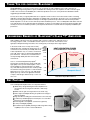
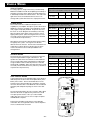
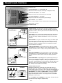
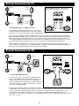
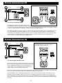
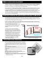
BLAUPUNKT SPECIFICATIONS -
PA275
AND
PA2100, 2/1 CHANNEL AMPLIFIER
Below is a basic trouble-shooting guide to assist in seeking out and correcting a problem that may occur in the installation
process. Although lengthy, this chart cannot address every single problem possible but mainly the ones most common.
PARAMETER/FEATURE
PA275
PA2100
Channels
2/1
2/1
Size ( W x H x D)
7.9 x7.5x2.6 inches (200x190x67mm) 7.9 x7.5x2.6 inches (200x190x67mm)
Weight (with housing)
4.6 lbs (2.1 kg)
4.6 lbs (2.1 kg)
Crimping style speaker terminals?
YES
YES
Maximum terminal wire size
14 ga.
14 ga.
Subsonic filter
YES (10 Hz)
YES (10 Hz)
Separate front/rear or left/right gains?
NO
NO
Fuse Type
ATC spade -30A
ATC spade -40A
Speaker short, short to +12V, and short to ground protection?
YES
YES
High, low, and reverse voltage protection?
YES
YES
Power output transistors
MOSFET
MOSFET
Switching power supply transistors
MOSFET
MOSFET
(non-bridged)
2 ohms
2 ohms
(bridged)
4 ohms
4 ohms
2 channels into 4 ohms / 2 ohms
2 x 75 W / 2 x 100 W
2 x 100 W / 2 x 150 W
1 channel into 4 ohms
1 x 200 W
1 x 300 W
0.03% THD
0.03% THD
82
82
>100
>100
Damping factor
>100
>100
Frequency response (full-range mode)
20 - 50,000 Hz
20 - 50,000 Hz
High-pass crossover frequency limits
50 H z - 250 Hz (variable), 12dB/oct
50 H z - 250 Hz (variable), 12dB/oct
Low-pass crossover frequency limits
50 H z - 250 Hz (variable), 12dB/oct
50 H z - 250 Hz (variable), 12dB/oct
Input impedance
10 kohms
10 kohms
Input signal voltage control range
0.3 - 6.0 vrms
0.3 - 6.0 vrms
Minimum speaker impedance
PERFORMANCE DATA
Rated power output @ 0.1% THD, 13.8V
Total Harmonic Distortion @ rated full output
Rated Signal/Noise ratio (averaged value)
Measured @ 1 watt / 1 kHz
dBA
Measured @ full rated power (0.1% THD) dBA
Current Draw @ 13.8 VDC (typical values @ X watts / Efficiency %)
@ full rated power, bridged mode
(@ 4 ohms)
28 A (65%)
36 A (65%)
@ full rated power, unbridged
(@ 4 ohms)
16 A (78%)
21 A (78%)
@ 33% rated power, unbridged
(@ 4 ohms)
6.0 A (60%)
8.0 A (60%)
@ 10% rated power, unbridged
(@ 4 ohms)
3.0 A (40%)
4.0 A (40%)
@ idle
(@ 4 ohms)
1.2 A
1.5 A
Minimum battery voltage to maintain rated power
12.6 VDC
12.6 VDC
Usable battery voltage
10 - 16 VDC
10 - 16 VDC
Trigger line voltage range
10 - 16 VDC
10 - 16 VDC
Trigger line current draw
@ 20 mA
@ 20 mA
Turn on delay time
@ 2.0 seconds
@ 2.0 seconds
Thermal shutoff temperature (average heat-sink temp)
@ 85˚ C (185˚ F)
@ 85˚ C (185˚ F)
NOTE: DUE TO ONGOING PRODUCT IMPROVEMENTS, DESIGN AND SPECIFICATIONS ARE SUBJECT TO CHANGE
WITHOUT ADVANCED NOTICE TO THE CONSUMER OR RETAILER.
TABLE OF CONTENTS
What is an amplifier? . . . . . . . . . . . . . . . . . . . . . . . . . . . . . . . . . . . . . . . . . . . . . . . . . . . . . . . . . . . . . . . . . . . . . . . . . . . . . . . . . . .2
Key features . . . . . . . . . . . . . . . . . . . . . . . . . . . . . . . . . . . . . . . . . . . . . . . . . . . . . . . . . . . . . . . . . . . . . . . . . . . . . . . . . . . . . . . . . .2
Safety Concerns & installation warnings . . . . . . . . . . . . . . . . . . . . . . . . . . . . . . . . . . . . . . . . . . . . . . . . . . . . . . . . . . . . . . . . . . .3
System planning . . . . . . . . . . . . . . . . . . . . . . . . . . . . . . . . . . . . . . . . . . . . . . . . . . . . . . . . . . . . . . . . . . . . . . . . . . . . . . . . . . . . . .4
Installation tools . . . . . . . . . . . . . . . . . . . . . . . . . . . . . . . . . . . . . . . . . . . . . . . . . . . . . . . . . . . . . . . . . . . . . . . . . . . . . . . . . . . . . . .4
Vehicle wiring . . . . . . . . . . . . . . . . . . . . . . . . . . . . . . . . . . . . . . . . . . . . . . . . . . . . . . . . . . . . . . . . . . . . . . . . . . . . . . . . . . . . . . . . .5
Connections & controls . . . . . . . . . . . . . . . . . . . . . . . . . . . . . . . . . . . . . . . . . . . . . . . . . . . . . . . . . . . . . . . . . . . . . . . . . . . . . . .6-7
System configurations 1 & 2 . . . . . . . . . . . . . . . . . . . . . . . . . . . . . . . . . . . . . . . . . . . . . . . . . . . . . . . . . . . . . . . . . . . . . . . . . . . . .8
System configurations 3 & 4 . . . . . . . . . . . . . . . . . . . . . . . . . . . . . . . . . . . . . . . . . . . . . . . . . . . . . . . . . . . . . . . . . . . . . . . . . . . . .9
Troubleshooting chart . . . . . . . . . . . . . . . . . . . . . . . . . . . . . . . . . . . . . . . . . . . . . . . . . . . . . . . . . . . . . . . . . . . . . . . . . . . . . . . . .10
Warranty information . . . . . . . . . . . . . . . . . . . . . . . . . . . . . . . . . . . . . . . . . . . . . . . . . . . . . . . . . . . . . . . . . . . . . . . . . . . . . . . . . .11
Blaupunkt technical support . . . . . . . . . . . . . . . . . . . . . . . . . . . . . . . . . . . . . . . . . . . . . . . . . . . . . . . . . . . . . . . . . . . . . . . . . . . .11
Assembly & Mounting . . . . . . . . . . . . . . . . . . . . . . . . . . . . . . . . . . . . . . . . . . . . . . . . . . . . . . . . . . . . . . . . . . . . . . . . .Back Cover
– 1 –– 1 –
THANK YOU
FOR CHOOSING
BLAUPUNKT!
Congratulations! You are the now the owner of an exceptional car audio amplifier from the audio enthusiasts at
Blaupunkt. Our engineering staff has spent considerable time refining our PA series amplifiers in order to introduce great
sound to the consumer at an affordable price. With these products we focus on sonic performance but balanced with
rugged design and flexible installation.
Not only do we offer you a great product but also a supportive owners manual. This manual can be used as a teaching
guide due to its brief, but informative, explanations of amplifier and system design. We are also very concerned about the
end consumer using proper installation techniques for the highest performance possible from their new audio products.
MOST important to us are the concerns with safety and the installation process. Since our Blaupunkt retail dealers have the
tools and experience for an optimized and safe installation, we always recommend they do the final vehicle integration. But,
should you choose to install these products yourself, please take the time to read this manual completely and abide by all
precautions.
ENGINEERING BENEFITS
OF
BLAUPUNKT’S CLASS “T” AMPLIFIERS
Audio amplifiers take power from the car battery and convert it to audio power. Although much of
the energy output is sound, a considerable amount of power is lost as heat. Such heat loss must
typically be dissipated via large heat sinks, thus creating heavy metal amps with a large footprint.
Total
In the audio world, Class ‘D’ amps have recently
Energy
helped reduce this wasted heat, allowing them to use Lost as
Heat
a smaller enclosure, but their poor fidelity limits them
(Watts)
to bass reproduction only. In contrast, conventional
150W
Class ‘AB’ amps march on with their high fidelity, but
poor efficiencies. Therefore, the need still exists for
125W
an amp with high fidelity, but with low heat and a
small chassis.
HEAT DISSIPATION CURVES
For 2x100 Watt Class ‘T’ and ‘AB’ Amps
Conventional
Class AB
100W
Class ‘T’, invented and patented by Tripath®
Technologies, provides the best of both worlds with
high quality sound, yet low heat dissipation. Due to
the remarkably low heat generated we can design
very small, hide-away boxes but also creatively shape
the external housings from plastics or other materials.
With heat losses of only 1⁄3 to 1⁄4 of an ‘AB’ design,
Tripath opens up a whole new application world for
compact, small design, attractive amps. Looks cool,
runs cool!
95W
Excess
Heat
75W
70W
Excess
Heat
50W
80W
Excess
Heat
Excess Energy
Wasted as Heat
Blaupunkt Class T
25W
0W
100W
Excess
Heat
IDLE
10
KEY FEATURES
Your new Blaupunkt Amplifier offers some important features:
■ “Break-away” design allowing the internal amplifier to be
removed from the housing and mounted in a “hide-away”
location
■ REM1, Remote gain control (operates in bass mode only)
■ HLA1, High Level Adapter allowing for speaker level voltage to
drive the amplifier
■ Plugs that allow for wiring the vehicle first then connect the amp
■ Continuously variable high-pass and low-pass crossover filters
■ Bass boost control (fixed gain)
■ Interchangeable colored plastic control lenses (optional)
■ 2 ohm (non-bridged) capability
■ 0.3-6.0Vrms input capability allowing for wide range drive voltage
capability from a receiver or other media device
–2 –
20
30
40
50
60
70
80
Audio Power Output (Watts/Channel)
90
100
SAFETY CONCERNS
We always recommend you have your Blaupunkt amplifiers professionally installed but the
installation process is often so easy that the average consumer can achieve success with little
trouble. Regardless of the person installing, you should be sure to review the following points
before proceeding with the installation:
■
READ THE MANUAL! Understanding the product and installation limitations before
lifting a screwdriver.
■
■
■
■
■
WEAR SAFETY GLASSES AT ALL TIMES - Flying debris are always dangerous.
PROTECT THE VEHICLE - Always disconnect the negative battery cable before
starting any kind of installation work. This prevents a possible high current electrical
short (potential fires).
HEAT - Keep all audio components away from nearby hot vehicle components that heat up over time such as hoses,
high current wires, and braking system components.
GIVE YOURSELF LOTS OF TIME - Rushing to complete an installation nearly always ends up with problems.
DO NOT LISTEN AT HIGH SOUND LEVELS FOR A PROLONGED TIME - these amplifiers, used with high
efficiency speakers from ANY manufacturer, have the potential to cause permanent hearing loss after listening at
maximum volume levels for several hours.
INSTALLATION WARNINGS!
Before disassembling your beautiful new car you need some basic installation knowledge and skill with common hand and
power tools. Following such basic installation tips and warnings will prevent possible damage to the vehicle and also
prevent possible fires.
■
AGAIN...READ THE MANUAL! There is a lot of helpful information in this manual that
■
COVER THE VEHICLE WORK AREAS - Use fender covers or blankets to protect the
will save time and prevent problems later.
work areas from scratches or dings.
■
■
■
■
■
■
■
■
DISCONNECT THE (-) LEAD ON THE BATTERY - No sparks or fires please!
“REVIEW” THE INSTALLATION - Before using any tools or moving vehicle
components, take five minutes to review the installation intentions (e.g., verify that an
amplifier will fit in an area of a car before tearing out all the interior).
“REVIEW” THE VEHICLE - Before drilling any holes or cutting into any surfaces, make
sure there are no fuel or hydraulic lines behind the surfaces. Also make sure there are no
wires routed directly behind or near the desired mounting area (remember...screws can
often extend 1-2 inches behind the mounting surface).
ENSURE PROPER FIT - Before cutting or drilling, make sure the amplifier will physically
fit in its desired location. Check for clearance around rear deck torsion bars or other
structural elements.
EVERY CAR IS ASSEMBLED DIFFERENT - Every auto manufacturer uses different
assembly techniques. Take care in removing/modifying all trim panels and mounting surfaces since they often use
unique screws or snap fasteners that are difficult to replace if they are lost or broken.
BE CAREFUL WITH CABLE ROUTING - When routing audio cables, make sure RCA and speaker wires are
routed away from high current power lines for audio amplifiers and vehicle systems lines when possible. This will
help prevent noises from creeping into the audio system, plus prevent potential damage to the vehicle wiring itself.
BE CAREFUL WITH ALL CONNECTIONS - When making connections, make sure each connection is clean
and properly secured. Observe all polarity markings carefully to ensure proper end performance.
CAUTION - FUEL TANKS AND FUEL LINES ARE NOW LOCATED DIRECTLY BENEATH THE REAR
DECK IN MANY CARS - CHECK FOR ADEQUATE CLEARANCE BEFORE EVEN CONSIDERING
SUCH A MOUNTING LOCATION!
–3 –
SYSTEM PLANNING
Before wiring up an audio system that may not achieve the
sound quality you want, be sure to choose a system concept
that fits your listening requirements. Basic systems, a
receiver with internal 4x20 watts and 4 coax speakers, are
adequate for many listeners. But, when you want to really
“feel” the music, you will need some kind of subwoofer
amplifier/speaker combination. Although many people might
jump into an “add-on” amplifier to power to rear coaxial
speakers, a better choice is usually a subwoofer
amp/speaker system that supplements the existing 4 speaker
system as shown in the adjacent drawing. Such a system
provides a surprising improvement in sound quality due to
the usually dramatic increase in bass response.
The next dramatic step up in performance is with a “multichannel” system that offers more dynamic range in the mids
and highs due to higher power plus more bass response due
to multiple woofers and/or more power. But, with such a
system, the stereo image and overall listening experience
usually becomes much more life-like due to better tonal
quality midrange/tweeter speakers and usually better
placement.
Full-Range
Full-Range
Subwoofer
Full-Range
Full-Range
Supplementary subwoofer system
Tuner
Passive X-over
Sat Amplifier (4x100 W)
To build such a system though, complexity goes up due to
the addition of passive or active crossovers which take time
to install and may inject noise into the system due to potential
noise signal pick up. The results though of such a system
can be dramatically pleasing.
Sub Amplifier (2x100 W)
Subwoofers
High performance multi-channel system
INSTALLATION TOOLS
For most installations, simple hand tools are adequate to install an aftermarket amplifier. Depending upon the mounting
locations used, you will need power tools for drilling and cutting plastics and metal. A good starting list is summarized
below:
■
■
■
■
■
■
■
■
■
Tape measure and ruler
Marking pen and starting punch
Phillips and flat blade screwdrivers (small and medium sizes)
Nylon wire bundle ties
Pliers: standard vice-grip and needle nose styles
Light-duty trim pry-bar for removing door trim
Cutting shears or nibbling tool for cutting thin and medium gauger metal
Wire cutters, wire strippers, electrical tape, crimping pliers and appropriate crimp-on
terminals
Power drill with appropriate sized drill bits
–4 –
VEHICLE WIRING
VEHICLE FUSING
For safety purposes, a high current fuse (or circuit breaker)
MUST be installed in line with the amplifiers(s) immediately at
the battery to prevent vehicle damage should the battery line
in advertently shorted to the vehicle chassis. The chart at the
right shows the recommended master fuse sizes for an
average audio system with noted “rms” output power levels.
POWER WIRING
Most vehicles built since 1990 have adequate current
capability for your amplifier. Except for systems above about
500 W rms, the factory charging system and battery should
easily support it if properly installed. Proper wire size must
be chosen to ensure adequate current delivery to the amp.
Wire size (gauge) of the cables need to increase in size for
higher power systems. (Wire sizes larger than those noted
are usually a waste of time and money since they offer Little
or no performance improvements.)
Wire diameter must increase (decreased wire gauge number)
for higher power systems. For long wire runs the wire
diameter must also increase. The wire sizes noted allow for a
maximum 0.5 volts DC drop over the give wire run which
results in Sound Pressure Level drops inaudible to the
average listener.
SPEAKER WIRING
As with power wire, speaker wire size (gauge) changes with
the power required and the length of the wire run. The
speaker wire chart shows the minimum recommended wire
size for a single audio output channel driving a loudspeaker
at a given distance with a maximum power loss of 0.5 dB,
the threshold of audibility. (Wire sizes larger than those noted
are usually a waste of time and money since they offer little or
no performance improvements.)
SYSTEM FUSE CHART
(Fuse size for total amplifier system power in “rms” watts)
Fuse Size
(in amps)
100 W
200 W
500 W
1000 W
20 A
30 A
50 A
100 A
SYSTEM POWER AND GROUND WIRE CHART
(Wire gauge for total system in 'rms' watts)
WIRE LENGTH
100 W
200 W
500 W
1000 W
5 ft. / 1.5 m
12
10
8
4
10 ft. / 3.0 m
12
10
8
4
15 ft. / 4.5 m
10
8
6
2
20 ft. / 6.0 m
10
8
6
2
25 ft. / 7.5 m
10
8
4
0 or 00
LOUDSPEAKER WIRE CHART
(Wire gauge per loudspeaker/speaker power in “rms” watts)
WIRE LENGTH
20 W
50 W
100 W
200 W
5 ft. / 1.5 m
18
16
16
16
10 ft. / 3.0 m
18
16
16
16
15 ft. / 4.5 m
16
16
16
14
20 ft. / 6.0 m
16
16
16
14
25 ft. / 7.5 m
16
16
14
12
FINAL VEHICLE WIRING
Current requirements for an upgraded audio system dictate a
dedicated power line be run from the amplifier directly to the
battery of the vehicle. This line should NOT be run to the
fuse panel of the vehicle but directly to the battery. DO NOT
run to the alternator either. There MUST be a fuse installed at
the battery with adequate amperage as shown in the chart
above.
Battery
Battery
Connector
Fuse or
Circuit
Breaker
Radio
As for the final signal wiring, be sure to route the audio cables
down the side of the car opposite the power lines to avoid
noise pick up from the lines. Also, try to route all audio
cables away from noise sources such as engine computers
and ABS brake computers.
Power Antenna
Turn-On Wire
(18-20 gage wire)
Speaker Wires
or
RCA Cables
Proper power grounding is important to insure adequate
current flow. Be sure to grind the surface clean of all paint to
ensure a solid electrical connection.
Speakers
Amplifier
Ground Screw
Drill 1/8” hole in
chassis sheet metal
Use the same ground if
using multiple amplifiers
–5 –
Grommet
To prevent
damage to
power wire
Power Wire
(10 gage
wire or
larger)
CONNECTIONS & CONTROLS
Line Level Input
(high-level w/adapter provided)
Ground
+12 (Battery)
Line Level Loop-Thru
Fuse
Remote Gain Control Input
Speaker Outputs & turn-on “trigger” line
POWER CONNECTIONS:
GROUND - This is the high current ground connection to the chassis of the
car. It should be fastened to a clean ground connection in the vehicle, capable
of handling high current loads. This wire should be no longer than 3 feet (1
meter)
+12v - A high current line run direct from the batter is highly recommended to
insure adequate current and voltage. This line MUST be run through a
dedicated fuse of some kind and this fuse should be located immediately next
to the power source. This in-line fuse is used to protect the vehicle should a
short to chassis occur.
TRIGGER - This line tells the amp to turn on and is remotely switched from
the radio which normally provides an amp “trigger” output. This line is
required to go “high” (+12V) to turn on the amp. If this line is not available, use
the power antenna line trigger which is normally available in most radios.
FUSE - This fuse is only for catastrophic situations should the amplifier begin to
self-destruct or incur installation situations where gross amounts of current are
being required from the amp beyond its design limits. Although another fuse
should be installed inline with the high power line at the battery, this amplifier
mounted fuse MUST remain in the circuit to protect the amplifier.
SPEAKER OUTPUTS - The amplifier is connected to appropriate impedance
speakers via these leads. It is IMPERATIVE that these leads NOT be
connected or touch the vehicle chassis in any way or the amplifier will be
damaged. The (+) and (-) leads of the amp are in no way inter-connected to
one another. Also, NONE of the leads can touch each other, touch ground, or
touch +12V or damage may occur to the amp or vehicle.
REMOTE GAIN CONTROL - This amplifier is provided with internal circuitry that
allows for a remote gain control to adjust the bass output level depending
upon the listener’s choice. ONLY the supplied gain control can be used with
the amp or the circuitry for it to be used properly.
CAUTION!! Unfortunately you CANNOT use simple telephone “Y” connectors
to daisy chain to multiple amps in hopes of controlling the gains of multiple
amps.
LINE LEVEL INPUTS - The most commonly used inputs in the aftermarket world
are RCA type line level inputs. These inputs can handle up to about 6 Volts
rms without overdriving the amplifier. Such high voltages are rarely found from
car audio head units so this is a very comfortable value. But, should the use
need to drive the amp directly from speaker level leads, use the supplied “High
Level Adapter” to connect to the amp.
LINE LEVEL LOOP-THRU - These connectors are simply hard wired to the other
inputs and do not loop-through the crossovers in any way. If you wish to
“daisy-chain” multiple amps simply connect them to the “loop-thru” leads.
–6 –
Power Terminal (+12V)
Connect directly to the vehicle battery (+)
terminal with 10 gage wire (minimum)
GND
+12V
NOT SUPPLIED
To Battery
Terminal
Fuse or
Circuit Breaker
10 Gage
Wire
Battery
Terminal
Adapter
Ground Terminal
Connect to a good chassis ground. The
ground connection should be clean,
unpainted metal to provide a good
electrical connection.
GND
+12V
Sheet
Metal
Screw
10 Gage
Wire
Ring
Connector
Drill 1/8” hole
in chassis
sheet metal
Remote Terminal
Connect the radio power antenna lead from
the receiver to the amplifier
terminal.
This turns the amplifier on whenever the
receiver is turned on.
18-20 Gage
Wire
To Receiver
Power
Antenna Lead
Butt
Connector
(not supplied)
CONNECTIONS & CONTROLS
POWER ON LED
CROSSOVER MODE: LP - FULLRANGE - HP
(Crossover is either in Low-pass, Full-range, or High-pass mode)
HIGH-PASS FREQUENCY: “50 - 250Hz”
(Frequencies above this setting will be passed through)
LOW-PASS FREQUENCY: “50 -250Hz”
(Frequencies below this setting will be passed through)
GAIN CONTROL : “0.3 - 6.0 Vrms”
(this is the input voltage necessary at this position for full output power)
BASS BOOST: “ON/OFF”
(+10dB when ON)
"Floating Ground"
Radio Outputs
(LOOP-THRU)
INPUTS
R
(BR)
L
L (+)
L (–)
black
gray
gray/black
"Common Ground"
Radio Outputs
(LOOP-THRU)
INPUTS
R
(BR)
L
L (+)
NOT USED
R (+)
black
gray/black
gray
(L) (GND)
(R)
"Ganged" 20k/ch
Resistor pack
LOW-PASS FREQUENCY - If the mode selector is in the “LP” position
the amplifier passes only low frequency sound. The upper limit for such
sound is set via this control. For bass, a value just below 100Hz is usually
best.
HIGH-PASS FREQUENCY - If the mode selector is in the “HP” position
the amplifier passes only mid and high frequency sound. The lower limit
for such sound is set via this control. A common setting is just above
100Hz.
CROSSOVER MODE - Depending upon the system design chosen, you
need to set the amplifier in the proper “mode” be it LP, Fullrange, or HP.
The low-pass and high-pass frequency settings are explained above. The
“full-range” setting simply allows for the amp to pass all audio frequencies
without any kind of crossover filter application. (This is common with
6x9” fullrange coaxial speakers for example.)
white/black
Radio chassis or
common speaker
ground
NOT USED
"HLA1"
High Level Adaptor
white
BASS BOOST - This control provides additional bass in the 45Hz area to
give a stronger low end “feel” to the bass. Once switched on, this will
also allow the amp to be driven into distortion sooner so the user must
be aware.
GAIN CONTROL - The gain control allows for a range of 0.3-6Volts input.
This means that if the setting is a 0.3V, it only takes 0.3Volts to drive the
amp to full output. (Such a low setting allows for the amp to be easily
overdriven and more susceptible to noise so a mid-position is highly
recommended for most radios.)
white/black
NOT
USED
R (+)
R (–)
"HLA1"
High Level Adaptor
white
POWER ON LED - This light will turn on when the amplifier receives a
+12V turn on signal from the radio. If the amp is properly wired, but the
light does not turn on, there may be a short circuit condition that the amp
is protecting itself from.
REMOTE GAIN
CIRCUITRY
REMOTE GAIN CIRCUITRY
Should the installer wish to create their own remote gain control, or
attempt to daisy chain the gains of multiple amps, refer to the adjacent
circuit design for proper connection. This should ONLY be attempted by a
very highly qualified installation technician. If improperly done DAMAGE
WILL OCCUR to the amplifier and WILL NOT be covered by warranty!
(We put this information in this manual because of the interest of our
highly skilled Blaupunkt installers - the average consumer should NOT
attempt this on their own!)
You should ONLY loop the SIGNAL pin to other amps - DO NOT carry the
ground and +12V pin voltages to adjacent amps.
–7 –
SYSTEM CONFIGURATION #1
Full-Range
Full-Range
or
High-Pass
Connect Speakers as shown. For best sound,
always make sure to connect + to + and - to -
X-OVER
MODE
LP
HP
Full-Range
FULL
Full-Range
or
High-Pass
2 Channel Full-range -or- High-Pass Mode
This installation is most popular for listeners who want to simply
increase the power to the rear speakers in a car. The resulting
performance is most commonly a louder overall sound field from the rear.
But, such a system’s biggest benefit is the additional bass response since the bass control of the radio can be turned up
without distorting the amplifier. Such a system is not necessarily louder in the mids and highs but is able to play louder in
the low frequencies due to this additional power. This leads to an overall richer and stronger sound experience for the
listener without additional subwoofer boxes or electronics that may complicate the system or take up more room. Such a
system WILL NOT equal the performance of a subwoofer system but will certainly be a pleasant improvement.
With the addition of a high-pass filter, this amplifier is set up to complement a dedicated subwoofer amplifier/speaker
system. This allows for smaller (e.g., 5" or 6") satellite speakers to operate most efficiently without being over-driven in the
bass region where a dedicated subwoofer system operates most efficiently.
SYSTEM CONFIGURATION #2
Full-Range
High-Pass
X-OVER
MODE
LP
HP
FULL
Subwoofer
High-Pass
Full-Range
3 Channel Multi-Mode (Passive)
The multi-mode system is a “poor-man’s” satellite/subwoofer
system. This amplifier is able to drive speakers in stereo mode
and at the same time drive low frequencies to a dedicated
subwoofer speaker. By inserting inductors (coils) and capacitors,
the result is an inexpensive solution to generating a ‘3' channel
system with a 2 channel amplifier.
Using passive components (coils and capacitors) the installation
is simple and performs adequately for most listeners. Such a system will not perform as well as an “active” system because
the slow attenuation (roll-off) of the frequency response resulting in a moderate amount of over-lapping of the sound
spectrum between the satellites and subwoofers. It is important to remember that although surprisingly pleasant
performance is achieved, this is a compromise system and will NOT perform as well as a dedicated 3 channel system with
electronic crossovers.
–8 –
SYSTEM CONFIGURATION #3
Full-Range
Full-Range
X-OVER
MODE
LP
HP
FULL
Subwoofer
Full-Range
Full-Range
2 Channel Dual Subwoofer Mode
The largest improvement in sound quality always comes
when adding some kind of subwoofer via a dedicated subwoofer amplifier and electronics crossover. The electronic
crossover ensures minimal overlap of the bass response with the mid and high frequencies from the other speakers resulting
in a more accurate performance compared to conventional coaxials with additional power.
By installing this amplifier in the stereo mode, you are able to drive two subwoofer speakers and in to low impedance loads
(e.g., 2 ohms) without over heating the amplifiers. Also, such an installation more easily supports a standard 2 speaker
woofer box that may already be constructed. Since two woofers can play 6 decibels louder than one at a given power (due
to acoustical laws of “mutual-coupling”), the resulting sound pressure level is substantial. This is probably the most
common use for a conventional two channel amplifier there is.
SYSTEM CONFIGURATION #4
Full-Range
For higher output, you can connect a subwoofer to
two output channels. Look for the + and – to
indicate the correct connections.
Full-Range
X-OVER
MODE
Subwoofer
LP
HP
Full-Range
Full-Range
FULL
1 Channel Bridged Subwoofer Mode
By electrically connecting a subwoofer speaker in the way shown
above, you are able to greatly increase the output power delivered
from the amplifier to the speaker. Such a circuit increases the
voltage “swing” across the speaker which increase the power
seen by a factor of 2 to 4 times that in stereo mode.
4Ω (main)
This is a very logical set-up for systems that are space limited to allow for only one subwoofer in a vehicle. The number and
box volumes are compensated by simply more amplifier power pushing a single speaker.
Such a configuration is also a surprisingly good performer. These increases in power are always welcome but you must
take care to avoid low impedances (below 4 ohms) since most amplifiers will overheat and shut down if over-driven into
such a configuration. You must also take care that you are not exceeding the thermal, or excursion, power limiting values
for the woofer. Surprisingly high power levels can be achieved with such a system without realizing it thus quickly damaging
the woofer.
–9 –
TROUBLE-SHOOTING GUIDE
Below is a basic trouble-shooting guide to assist in seeking out and correcting a problem that may occur in the installation
process. Although lengthy, this chart cannot address every single problem possible but mainly the ones most common.
SYMPTOM
PROBABLE CAUSE OR CORRECTION
No power (power light not on)
■
■
■
■
■
Power but no sound (power light is on)
■
■
No sound from one channel or entire side
■
■
■
Very low sound level
■
■
■
Power amplifier turns on and off repeatedly
(motor-boating sound)
■
■
■
Amplifier turns off during loud or distorted
passages
■
■
■
■
Amplifier performs fine but gets very hot to
the touch
■
■
■
Amplifier turn-on/turn-off pops or noises
■
■
Cracking noises on AM/FM radio but not
on tape or cd.
■
■
■
■
Whining noise, engine running, varies in
pitch or loudness with engine speed, AND
varies with radio volume control setting
(this is generally a RADIO installation
problem)
■
■
■
■
Whining noise, engine running, varies in
pitch or loudness with engine speed, BUT,
DOES NOT vary with radio volume control
setting (this is generally an amplifier
installation problem)
■
■
■
■
Check connections to amps +12 volt, ground, and remote lines.
Use voltmeter to verify voltages are at terminals of amp.
Check main power connection at battery.
Check fuse in power line at battery.
Disconnect all speakers but not power lines - if unit then turns on, a speaker short
or speaker line touching vehicle chassis is likely.
Check all input cable lines for connection.
Disconnect speakers from amp, test speaker lines with digital voltmeter to verify >2
ohms per channel (non-bridged mode).
Check radio’s balance and fader control positions - verify they are at center.
Check speaker connections at amp and speaker.
Check input leads for connection to amp.
Verify radio balance and fader controls are at center positions.
Check amplifier’s input gain control setting - adjust for higher output levels if
necessary (gain settings closer to 0.3 volts).
Receiver may have very low output voltage levels - a step up “line driver” may
have to be used.
Make sure power connections at batter are tight.
Verify battery voltage is >11.5 volts DC (12.5-15V engine on) at amplifier with engine off.
Check all radio and amplifier ground connections.
Input stage being over-driven - lower input gain (closer to 4 volt setting).
Verify battery voltage is >11.5 volts DC at amplifier with engine off.
Check all radio and amplifier ground connections.
Verify speaker loads >2 ohms on all channels (non-bridged mode).
Input gain control too high - lower accordingly (closer to 4.0 volt setting).
Verify speaker loads >2 ohms on all channels (non-bridged mode).
Verify the mounting location allows for free air movement around the amp.
Preferably, the amp should be mounted with fins up and down so rising heat moves
quickly away from amp.
“turn on race” - disconnect trigger from radio and turn on/off via a wire jumper to
power terminal. If noise goes away, the radio is turning on/off too slowly. This is
radio problem and can only be corrected with outboard turn-on delay relay system.
Radio “thump” - disconnect the RCA input lines to the amp and turn on/off via radio
trigger. If noise goes away without RCA lines connected, the radio is sending pops
out through RCA lines. This is a radio problem and can only be corrected with
outboard turn-on delay relay system.
Ensure the problem is “radiated noise” by placing a portable FM radio near the car
engine. If noise is picked up, then it is a vehicle problem and not your system.
Research to isolate the source and properly shield or bypass.
Are spark plugs and wires > 3 years old? These can often radiate substantial noise
when old.
Verify the engine block has a good ground connection to chassis ground.
Verify the engine compartment hood is grounded to vehicle chassis via a braided
grounding strap.
Verify all power and ground connections are clean at radio.
Re-route radio power and ground so they are sourced from same connections back
at amplifier (this is called a “common” ground).
Check all ground connections to ensure clean surfaces that have all paint removed
and also not oxidation buildup over time.
Verify there is some kind of power filtering choke assembly at back of radio. If not,
install one.
Check battery ground connections at chassis are clean and tight, scraped free of
oxidation, paint, and grease.
Re-route radio power and ground so they are sourced from same connections back
at amplifier (this is called a “common” ground).
Bypass all equipment between radio and amp (e.g., equalizers) directly connecting
radio. If noise goes away, signal processor has problem.
Check for signal level “ground loops” - disconnect the outer shield of the RCA cable
at one end of the cable (e.g., radio end). If noise goes away, modify cables
accordingly. There are voltage differences at the ground connections of the
components and these are NOT correctable any other way than such shield cutting
or an outboard “ground loop isolator” which is a small transformer.
– 10 –
LIMITED WARRANTY INFORMATION (UNITED STATES ONLY)
Robert Bosch Corporation warrants new Blaupunkt car audio products it distributes in the United States through authorized Blaupunkt
dealers, or which are imported as original vehicle equipment by the automobile manufacturer, to be free from defects in material and
workmanship, in accordance with the following:
For twelve (12) months after delivery to you, the original consumer purchaser, we will repair or at our option replace at no charge to you
any car audio product which, under normal conditions of use and service, proves to be defective in materials or workmanship.
However, this warranty does not cover expenses incurred in the removal or reinstallation of any car audio product, whether or not
proven defective, and does not cover products not purchased from an authorized Blaupunkt dealer. This warranty is limited to the
original consumer purchaser and is not transferable. Repaired and replacement car audio products shall assume the identity of the
original for purpose of this warranty and this warranty shall not be extended with respect to such products.
To obtain performance of this warranty, contact the nearest Blaupunkt authorized repair facility or our nearest office. A dated purchase
receipt or other proof that the product is within the warranty period will be required in order to honor your claim. Carefully pack the unit
and ship prepaid to the servicing location. For further information, write to the Robert Bosch Corporation, 2800 South 25th Avenue,
Broadview, Illinois, 60153, attention Blaupunkt Customer Service Department or call 1-800-266-2528.
Specifically excluded from this warranty are failures caused by misuse, neglect, abuse, improper operation or installation, dropping or
damaging, unauthorized service or parts, or failure to follow maintenance instructions or perform normal maintenance activities.
Normal maintenance activities for car audio products include but are not limited to cleaning and other minor maintenance activities and
adjustments that are outlined in the owner's manual or that are normally required for continued proper operation. Also excluded from
this warranty is the correction of improper installation and the elimination of any external electromagnetic interference. This warranty
sets forth your exclusive remedies with respect to the products covered by it. We shall not be liable for any incidental, consequential,
special or punitive damages arising from the sale or use of any Blaupunkt car audio products, whether such claim is in contract or tort.
No attempt to alter, modify, or amend this warranty shall be effective unless authorized in writing by an officer of Robert Bosch
Corporation.
THIS WARRANTY IS IN LIEU OF ALL OTHER WARRANTIES OR REPRESENTATIONS, EXPRESS OR IMPLIED, INCLUDING ANY
WARRANTY IMPLIED BY LAW, WHETHER FOR MERCHANTABILITY OR FITNESS FOR A PARTICULAR PURPOSE OR OTHERWISE
AND SHALL BE EFFECTIVE ONLY FOR THE PERIOD THAT THIS EXPRESS WARRANTY IS EFFECTIVE.
In the event any provision, or any part or portion of this warranty shall be held invalid, void or otherwise unenforceable, such holding
shall not affect the remaining part or portions of that provision or any other provision hereof.
NOTICE TO CALIFORNIA OWNERS: If your Blaupunkt car audio product needs warranty repair service and there is no authorized
service center reasonably close to you, you can return the defective unit to the dealer from whom you purchased it, or you can return it
to any dealer who sells Blaupunkt car audio products. The dealer may, at the dealer's option, replace, repair or refund the purchase
price for any Blaupunkt car audio products which prove defective under conditions of normal use. If the dealer fails to repair, replace, or
partially refund your money, you may take your Blaupunkt car audio product to any repair shop and they can repair your unit at our
expense unless the repair cost exceeds the depreciated value of the unit, but you must contact Blaupunkt to receive authorization to
do this before your car audio product is repaired.
ROBERT BOSCH CORPORATION
BLAUPUNKT CUSTOMER SERVICE
2800 SOUTH 25TH AVENUE
BROADVIEW, IL 60155
TEL: 1-800-266-2528
BLAUPUNKT TECHNICAL SUPPORT
These amplifiers are designed to install quickly and easily into most vehicles. Should you experience installation problems,
we will make all reasonable efforts to help you, the end purchaser or Installation Technician, to competently install these
components. Before calling us please carefully review this owners manual for
the answers to your questions.
Due to the limited print space of this owners manual, we also offer additional
information regarding installation and systems on our Internet site. Via a
standard Internet connection through a local Internet Service Provider or other
providers (e.g., America Online), connect to our web site at the following
address: www.BlaupunktUSAcom. On this site we offer technical information
on system design, vehicle integration, product fit guides where possible, and
extensive information on loudspeaker design and installation. For the more
adventuresome builder, we also offer our “BlauBox” computer program which
assists in designing subwoofer enclosures. This program is FREE to down load
and use. We also “link out” to other sites that provide additional theory and
technical support for the consumer and the technically interested.
– 11 –
MERCI D’AVOIR CHOISI BLAUPUNKT!
Félicitations ! Vous êtes maintenant propriétaire d’un amplificateur pour autoradio exceptionnel, produit par les audiophiles
enthousiastes de Blaupunkt. Notre équipe d’ingénieurs a passé un temps considérable à raffiner notre ligne d’amplificateurs
PA, afin de vous apporter un son remarquable à un prix abordable. Nous nous concentrons avec ces produits sur la
performance sonore, alliée à une conception solide et à une installation flexible.
Nous vous offrons non seulement un produit remarquable, mais également un manuel du propriétaire pratique. Ce manuel
peut être utilisé comme un guide d’apprentissage, grâce à ses explications brèves mais informatives sur la conception des
systèmes et des amplificateurs. Nous voulons également nous assurer que le consommateur utilisera des techniques
d’installation appropriées afin de tirer la meilleure performance possible de leur nouveau matériel audio. Nos préoccupations
MAJEURES sont la sécurité et le processus d’installation. Nos revendeurs Blaupunkt ayant les outils et l’expérience
nécessaires à une installation sûre et optimale, nous recommandons toujours qu’ils se chargent de l’intégration finale au
véhicule. Toutefois, si vous décidez d’installer ces produits vous-même, veuillez prendre le temps de lire ce manuel jusqu’au
bout et d’en observer toutes les précautions.
AVANTAGES TECHNIQUES DES AMPLIFICATEURS DE CLASSE T DE BLAUPUNKT
Les amplificateurs audio reçoivent leur alimentation des batteries de voiture et la convertissent en puissance audio. Bien
qu’une grande partie de l’énergie de sortie soit sonore, une puissance considérable est perdue sous forme de chaleur. Cette
perte calorifique doit généralement être dissipée au moyen de dissipateurs thermiques de grandes dimensions, ce qui crée
des amplis lourds en métal occupant une place importante.
Dans le monde audio, les amplis de Classe “D” ont aidé récemment à réduire cette énergie gaspillée, ce qui leur permet
d’utiliser une enceinte plus petite, mais leur fidélité médiocre les limite à ne reproduire que les graves. Par contre, les amplis
“AB” classiques défilent avec leur fidélité élevée, mais
cela au prix de rendements médiocres. Par
Énergie totale
conséquent, le besoin existe encore d’avoir un ampli
perdue sous
Courbes de dissipation de chaleur
forme
qui ait une fidélité élevée, tout en émettant peu de
de chaleur
Pour amplis de Classe “T” et “AB” 2x100 Watts
chaleur et se logeant dans un châssis de petites
(Watts)
dimensions.
150W
Classe AB
classique
La Classe “T” inventée et brevetée par Tripath
125W
Technologies procure ce qu’il y a de mieux dans les
100W
80W
deux mondes en ayant un son de haute qualité tout en
Chaleur
100W
Chaleur
95W
en excès
en excès
dissipant peu de chaleur. Par suite de la chaleur créée
Chaleur
en
excès
Énergie
en
excès
gaspillée
remarquablement faible, nous pouvons concevoir de
75W
sous forme de chaleur
70W
très petites boîtes qui se cachent, mais nous pouvons
Chaleur
aussi donner de façon créative aux logements des
en excès
50W
formes en plastique ou en d’autres matériaux. Avec
des pertes thermiques qui sont seulement entre 1/3 et
Blaupunkt Class T
25W
_ de celles d’une conception “AB”, Tripath ouvre tout
un monde nouveau d’applications à des amplis
0W
IDLE
10
20
30
40
50
60
70
80
90
100
compacts, petits et séduisants. Ayez l’air froid,
Puissance de sortie audio (Watts/Canal)
fonctionnez de manière froide !
CARACTÉRISTIQUES PRINCIPALES
Votre nouvel amplificateur Blaupunkt offre des particularités importantes :
■ Conception "Break-away" (À décollement) permettant à l’amplificateur
interne d’être retiré du logement et monté dans un emplacement caché
■ REM1, Réglage du gain à distance (fonctionne seulement en mode des
graves)
■ HLA1, Adaptateur à niveau élevé tenant compte de la tension au niveau
haut-parleur pour piloter l’amplificateur
■ Fiches qui permettent de câbler d’abord le véhicule, puis de connecter
l’amplificateur
■ Filtres de sélection de fréquences passe-haut et passe-bas continûment
variable
■ Réglage d’amplification des basses fréquences (gain fixé)
■ Lentilles de réglage interchangeables en plastique coloré (en option)
■ Capabilité de 2 ohms (sans chevauchement)
■ Capabilité d’entrée de 0.3-6.0Veff prévoyant une capabilité de tensions de
pilotage dans une gamme étendue provenant d’un récepteur ou d’un
autre dispositif de média
– 12 –
ASSEMBLY & MOUNTING
Robert Bosch Corporation, Sales Group
Mobile Communications Division
2800 South 25th Avenue, Broadview, IL 60155
www.BlaupunktUSA.com
Copyright 2001 by the Robert Bosch Corporation
No portion of this work may be reproduced in any form without the written consent of the Robert Bosch Corporation
Tripath logo, name, and patents are protected by Tripath Corp, Santa Clara, CA
Printed in China (May, 2001)