1
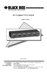
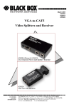
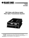
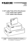
Mini-CAT5 Video-over-CAT5 Extension
Model AC504A
VGA Extension
Model AC504A-CP
Component Video (RGB or Y Cb Cr) Extension
March 2004
CUSTOMER
SUPPORT
INFORMATION
Order toll-free in the U.S. 24 hours, 7 A.M. Monday to midnight Friday:
877-877-BBOX
FREE technical support, 24 hours a day, 7 days a week:
Call 724-746-5500 or fax 724-746-0746
Mail order: Black Box Corporation, 1000 Park Drive, Lawrence, PA 15055
Web site: www.blackbox.com • E-mail: [email protected]
ss
VGA & Component Video-over-CAT5 Extension
TRADEMARKS USED IN THIS MANUAL
(logo) are trademarks of Black Box Corporation.
Black Box, and
IBM is a registered trademark of International Business Machines
Corporation. Any other trademarks mentioned in this manual are
acknowledged to be the property of the trademark owners.
FEDERAL COMMUNICATIONS COMMISSION
RADIO FREQUENCY INTERFERENCE STATEMENT
This equipment generates, uses, and can radiate radio frequency energy
and if not installed and used properly, that is, in strict accordance with
the manufacturer’s instructions, may cause interference to radio
communication. It has been designed and found to comply with the
limits for a Class A computing device in accordance with the
specifications in Subpart B of Part 15 of FCC rules, which are intended
to provide reasonable protection against such interference when the
equipment is operated in a commercial environment. Operation of this
equipment in a residential area is likely to cause interference, in which
case the user at his or her own expense will be required to take
whatever measures may be necessary to correct the interference.
Changes or modifications not expressly approved by the party
responsible for compliance could void the user’s authority to operate
the equipment.
This digital apparatus does not exceed the Class A limits for radio
noise emission from digital apparatus set out in the Radio Interference
Regulation of the Canadian Department of Communications.
EUROPEAN UNION DECLARATION OF CONFORMITY
This product complies with the requirements of the European EMC
directive 89/336/EEC
1
Model AC504A & AC504A-CP
Normas Oficiales Mexicanas (NOM)
Electrical Safety Statement
INSTRUCCIONES DE SEGURIDAD
1. Todas las instrucciones de seguridad y operación deberán ser leídas
antes de que el aparato eléctrico sea operado.
2. Las instrucciones de seguridad y operación deberán ser guardadas para
referencia futura.
3. Todas las advertencias en el aparato eléctrico y en sus instrucciones de
operación deben ser respetadas.
4. Todas las instrucciones de operación y uso deben ser seguidas.
5. El aparato eléctrico no deberá ser usado cerca del agua—por ejemplo,
cerca de la tina de baño, lavabo, sótano mojado o cerca de una alberca,
etc.
6. El aparato eléctrico debe ser usado únicamente con carritos o pedestales
que sean recomendados por el fabricante.
7. El aparato eléctrico debe ser montado a la pared o al techo sólo como
sea recomendado por el fabricante.
8. Servicio—El usuario no debe intentar dar servicio al equipo eléctrico
más allá a lo descrito en las instrucciones de operación. Todo otro
servicio deberá ser referido a personal de servicio calificado.
9. El aparato eléctrico debe ser situado de tal manera que su posición no
interfiera su uso. La colocación del aparato eléctrico sobre una cama,
sofá, alfombra o superficie similar puede bloquea la ventilación, no se
debe colocar en libreros o gabinetes que impidan el flujo de aire por los
orificios de ventilación.
10. El equipo eléctrico deber ser situado fuera del alcance de fuentes de
calor como radiadores, registros de calor, estufas u otros aparatos
(incluyendo amplificadores) que producen calor.
2
ss
VGA & Component Video-over-CAT5 Extension
11. El aparato eléctrico deberá ser connectado a una fuente de poder sólo
del tipo descrito en el instructivo de operación, o como se indique en el
aparato.
12. Precaución debe ser tomada de tal manera que la tierra fisica y la
polarización del equipo no sea eliminada.
13. Los cables de la fuente de poder deben ser guiados de tal manera que no
sean pisados ni pellizcados por objetos colocados sobre o contra ellos,
poniendo particular atención a los contactos y receptáculos donde salen
del aparato.
14. El equipo eléctrico debe ser limpiado únicamente de acuerdo a las
recomendaciones del fabricante.
15. En caso de existir, una antena externa deberá ser localizada lejos de las
lineas de energia.
16. El cable de corriente deberá ser desconectado del cuando el equipo no
sea usado por un largo periodo de tiempo.
17. Cuidado debe ser tomado de tal manera que objectos liquidos no sean
derramados sobre la cubierta u orificios de ventilación.
18. Servicio por personal calificado deberá ser provisto cuando:
A: El cable de poder o el contacto ha sido dañado; u
B: Objectos han caído o líquido ha sido derramado dentro del aparato;
o
C: El aparato ha sido expuesto a la lluvia; o
D: El aparato parece no operar normalmente o muestra un cambio en su
desempeño; o
E: El aparato ha sido tirado o su cubierta ha sido dañada.
3
Model AC504A & AC504A-CP
Contents
1. Introduction ............................................................................page 5
1.1 Model AC504A for VGA .....................................................page 5
1.2 Model AC504A-CP for Component Video (RGB or Y Cb Cr) ..page 5
1.3 Features ..................................................................................page 6
2. Installation................................................................................page 6
3. Configuration and Operation .................................................page 8
4. Troubleshooting .......................................................................page 9
Contacting Black Box ..............................................................page 10
Shipping & Packaging..............................................................page 10
5. Specifications..........................................................................page 11
4
ss
VGA & Component Video-over-CAT5 Extension
1. Introduction
1.1 Model AC504A … for VGA
The Model AC504A is a UTP (CAT5) VGA video extender consisting
of a transmitter (AC504A-S) and a receiver (AC504A-R) sold together
as a pair. The transmitter converts a PC's VGA signal into a format that
can be transmitted using a single inexpensive and commonly available
Category-5 Unshielded Twisted Pair (UTP) cable with RJ45
connectors, which is used in most Local Area Networks.
At the receiving (remote) end the Cat5 signal is converted back to VGA
for connection to your monitor, projector or other display device.
The transmitter and receiver are each housed in a small plastic
enclosure and include a HD15 video connector and a RJ45 connector
for the Cat-5 cable. Included with the pair of devices are: one small
universal power supply (can be powered at either end), and a short
adapter cable for easy connection to the standard HD-15 connector of
the PC.
The Mini-CAT5 Extender can drive CAT5 LAN cables to 500 feet (150
meters) with excellent video quality.
1.2 Model AC504A-CP … for Component Video (RGB or
YPbPr or YCbCr)
This variation of the AC504A includes cables for each end that allow
connection of the transmitter to the 3 RCA connectors of DVD-players
or other video sources that output Component Video (RGB or Y Pb Pr,
or Y Cb Cr). A similar cable is also provided for the receiver for
connection to compatible displays such as HDTV’s or high-end
monitors. The actual sender and receiver units are identical to the
standard AC504A and, in fact, you can use the pair to send VGA video
if you substitute VGA cables.
5
Model AC504A & AC504A-CP
1.3 Features
•
Eliminates the need for bulky , expensive and hard to build
multi-coaxial cables for high-resolution video extension
•
Amplifies the signal for clean and crisp transmission
•
Differential signaling eliminates ground loops and noise
•
Handles resolutions up to 1600x1200 at any refresh rate
•
Rugged, Reliable, Compact size
•
Only one end requires power in most applications. Power
supply can be connected at the sending or the receiving end,
whichever convenient.
•
Drive standard CAT5 cables to 500 feet (for VGA and
Component video versions) or to 1200 feet for (Composite
Video and Stereo Audio version)
•
Perfect for Remote Monitoring, Video Staging, Conference
Rooms, Classrooms, Home-Theatre Applications and more
2. Installation
1.
Connect the VGA in (HD-15) connector of the AC504A
Transmitter to the computer's or other equipment’s video output
port using the supplied cable (see figure 2.1).
CAT-5
Receiver
Sender
VGA
VGA
Remote Monitor
Figure 2.1
2.
Connect the included power adapter to the power connector on
either of the transmitter or the receiver (for more information,
please see the recommendations immediately following this
paragraph). Be sure to insert the power connector fully. Check the
red light next to the RJ45 connector to verify unit’s power. When
the two units are connected Via CAT5 cable, the LED’s at both
ends should be lit.
6
ss
VGA & Component Video-over-CAT5 Extension
Recommended Power Supply Connection
q
Cat 5 cable length of 0 to 150 feet:
It does not matter in which end you plug the power supply. Use
whichever end that is most convenient for your setup.
q Cat 5 cable length of 150 to 300 feet:
We recommend that you plug the power supply a the receiving end.
q Cat 5 cable length of 300 to 500 feet:
Please plug the power supply at the receiving end, however,
depending the grounding of the video source (PC) and the display
device at the remote end, you may need to purchase an additional
power supply to power up both ends.
q Cat 5 cable lengths over 500 feet:
Purchase of an additional power supply to power up both ends is
almost certainly needed.
3.
Using Category-5 cable connect the AC504A-Receiver to the
transmitter’s RJ45 output. Connect the remote monitor to the
receiver either directly (VGA) or using the HD15 to 3 RCA cable
(Component Video).
IMPORTANT
Do not connect this unit to any LAN device such as network cards or hubs
as this may cause damage. Use EIA/TIA 568B standard straight-through
patch wiring as shown below. Do not use crossover cables.
EIA/TIA 568B WIRING STANDARD
PIN
Wire Color
1
White w/ Orange Stripe
2
Orange
3
White w/Green Stripe
4
Blue
5
White w/Blue Stripe
6
Green
7
White w/Brown Stripe
8
Brown
7
Model AC504A & AC504A-CP
3. Configuration & Operation
The Mini-CAT5 Receivers are equipped with an adjustment to improve
image quality when using long cables. The adjustment is made via a
single turn trim-pot located next to the power connector on the side.
When using a long cable, with no
compensation, any solid horizontal line,
tends to smear to the right. For example
in the image shown on the right, observe
the dark black line at the bottom of the
window and see how it is smearing to
the right (not changing to white abruptly
as it should). This is the effect of long
No-Compensation
cable on the signal.
You can turn the trim-pot to eliminate
these streaks as shown on the 2nd
picture. If you add too much
compensation to the signal, then an
opposite effect may be observed, i.e.
black lines smear to the right as white
lines or vice-versa. The 3rd picture
shows the case where too much
compensation is added.
When using long cables, the image
quality is a function of resolution and
refresh rate. Lower resolution or refresh
rate, result in best picture. Therefore it is
best to set the refresh rate to 60 Hz at
any resolution.
Perfect Compensation
Too much Compensation
Figure 3.1
Although the Mini-CAT5 extenders are compatible with all varieties of
UTP cable, for best results at long distances, use standard Category-5
Cable (instead of CAT5e or CAT6).
8
ss
VGA & Component Video-over-CAT5 Extension
4. Troubleshooting
1.
Fuzzy, blurry, or ghosting image at remote location
If you have a stable image but it looks somewhat blurry (object or
character edges are not sharp), try to adjust the compensation first.
When the trim-pot is turned fully CCW there is no compensation. As
you turn the pot clockwise you are applying compensation. Look at the
screen and slowly turn the pot clockwise. Notice what happens to the
right of solid horizontal lines (as in figure 3.1). If you still have a fuzzy
image, try reducing first the refresh rate and then the resolution of the
PC.
2.
Shaking image or periodically blanking monitor
CAT5 cable employs twisted pairs to differentially transmit the signals
from the transmitter to the receiver in order to reduce the amount of
EMI (interference) coupled noise from external sources. However, a
strong electromagnetic noise field can cause instability in the signal.
Usual sources of this form of noise coupling are high current AC lines
or other high-density data and/or control cables that run adjacent to and
parallel with a substantial length of the CAT5 cable.
To eliminate this, either separate the Cat 5 cable of Mini-CAT5
Extender from the interfering source or use shielded CAT5 cables. Note
that separating the CAT5 cable from the EMI source by a few inches is
often sufficient to eliminate this problem.
3.
The PC does not recognize a Plug-and-Play monitor
If the PC’s Operating System is setup to detect a plug-and-play monitor
(usually in Display Properties Advanced Settings), it may have trouble
finding a monitor. If the PC does not produce an image due to this,
disable the plug-and-play monitor detection in the PC’s operating
system Display Properties.
4.
Substituting power supplies
The sender and receiver rely on the power adapter that is supplied with
them. Do not substitute any other power supply or DC power source
9
Model AC504A & AC504A-CP
Contacting Black Box
If you determine that your extender is malfunctioning, do not attempt to
repair the unit. Contact Black Box Tech. Support at 724-746-5500.
Before you do, make a record of the history of the problem. We will be
able to provide more efficient and accurate assistance if you have a
complete description.
Shipping and Packaging
If you need to transport or ship your extender:
• Package it carefully. We recommend that you use the original
container.
• Before you ship the units back to Black Box Corporation for
repair or return, contact us to get a Return Authorization (RA)
number.
10
ss
VGA & Component Video-over-CAT5 Extension
5. Specifications
Video Types
Model AC504A:
VGA through UXGA
Model AC504A-CP: RGB , YPbPr , or YCbCr
Resolution
Up to 1600 x 1200 at up to 85 Hz
Bandwidth
DC to 250 MHz
Max. Distance Up to 500 ft. (150 m)
Connectors
HD15 female for video in and out; Shielded RJ45
Interfaces
Standard Analog VGA; Proprietary CAT5
Compliance
CE; FCC Part 15 Subpart B Class A, IC Class
Max. Altitude 10,000 ft. (3048 m)
Temperature Operating: 32 to 122°F (0 to 50°C);
Storage: –40 to +185°F (–40 to +85°C)
Humidity
Up to 95% non-condensing
Enclosure
Plastic ABS-94VO, UL File#56070
MTBF
90,000 hours (calculated estimate)
Power
From utility-power (mains) outlet, through included
external power adapter. Output Voltage: 9v DC
regulated Center-Positive. Power :(5 watts Max)
Size
Transmitter & Receiver
Weight
2 lbs. (shipping)
0.8” H x 1.7” W x 4.5” L
11
Model AC504A & AC504A-CP
12
© Copyright 2004. Black Box Corporation..
All rights reserved.
1000 Park Drive
Lawrence, PA 15055-1018
724-746-5500
Fax 724-746-0746