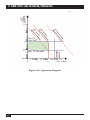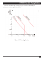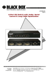
1
MARCH 2000
39004
39005
T1 Fiber Optic Line Extender/Simulator
TX
FO TX
RX
FO/S
C
RX
I/F
LL
CUSTOMER
SUPPORT
INFORMATION
DL
P
LOO
Order toll-free in the U.S. 24 hours, 7 A.M. Monday to midnight Friday: 877-877-BBOX
FREE technical support, 24 hours a day, 7 days a week: Call 724-746-5500 or fax 724-746-0746
Mail order: Black Box Corporation, 1000 Park Drive, Lawrence, PA 15055-1018
Web site: www.blackbox.com • E-mail: [email protected]
FCC INFORMATION
FEDERAL COMMUNICATIONS COMMISSION
AND
INDUSTRY CANADA
RADIO FREQUENCY INTERFERENCE STATEMENTS
This equipment generates, uses, and can radiate radio frequency energy and if not
installed and used properly, that is, in strict accordance with the manufacturer’s
instructions, may cause interference to radio communication. It has been tested
and found to comply with the limits for a Class A computing device in accordance
with the specifications in Subpart J of Part 15 of FCC rules, which are designed to
provide reasonable protection against such interference when the equipment is
operated in a commercial environment. Operation of this equipment in a
residential area is likely to cause interference, in which case the user at his own
expense will be required to take whatever measures may be necessary to correct the
interference.
Changes or modifications not expressly approved by the party responsible for
compliance could void the user’s authority to operate the equipment.
This digital apparatus does not exceed the Class A limits for radio noise emission from digital
apparatus set out in the Radio Interference Regulation of Industry Canada.
Le présent appareil numérique n’émet pas de bruits radioélectriques dépassant les limites
applicables aux appareils numériques de la classe A prescrites dans le Règlement sur le
brouillage radioélectrique publié par Industrie Canada.
1
T1 FIBER OPTIC LINE EXTENDER/SIMULATOR
NORMAS OFICIALES MEXICANAS (NOM)
ELECTRICAL SAFETY STATEMENT
INSTRUCCIONES DE SEGURIDAD
1. Todas las instrucciones de seguridad y operación deberán ser leídas antes de
que el aparato eléctrico sea operado.
2. Las instrucciones de seguridad y operación deberán ser guardadas para
referencia futura.
3. Todas las advertencias en el aparato eléctrico y en sus instrucciones de
operación deben ser respetadas.
4. Todas las instrucciones de operación y uso deben ser seguidas.
5. El aparato eléctrico no deberá ser usado cerca del agua—por ejemplo, cerca
de la tina de baño, lavabo, sótano mojado o cerca de una alberca, etc..
6. El aparato eléctrico debe ser usado únicamente con carritos o pedestales que
sean recomendados por el fabricante.
7. El aparato eléctrico debe ser montado a la pared o al techo sólo como sea
recomendado por el fabricante.
8. Servicio—El usuario no debe intentar dar servicio al equipo eléctrico más allá
a lo descrito en las instrucciones de operación. Todo otro servicio deberá ser
referido a personal de servicio calificado.
9. El aparato eléctrico debe ser situado de tal manera que su posición no
interfiera su uso. La colocación del aparato eléctrico sobre una cama, sofá,
alfombra o superficie similar puede bloquea la ventilación, no se debe colocar
en libreros o gabinetes que impidan el flujo de aire por los orificios de
ventilación.
10. El equipo eléctrico deber ser situado fuera del alcance de fuentes de calor
como radiadores, registros de calor, estufas u otros aparatos (incluyendo
amplificadores) que producen calor.
11. El aparato eléctrico deberá ser connectado a una fuente de poder sólo del
tipo descrito en el instructivo de operación, o como se indique en el aparato.
2
NOM STATEMENT
12. Precaución debe ser tomada de tal manera que la tierra fisica y la polarización
del equipo no sea eliminada.
13. Los cables de la fuente de poder deben ser guiados de tal manera que no
sean pisados ni pellizcados por objetos colocados sobre o contra ellos,
poniendo particular atención a los contactos y receptáculos donde salen del
aparato.
14. El equipo eléctrico debe ser limpiado únicamente de acuerdo a las
recomendaciones del fabricante.
15. En caso de existir, una antena externa deberá ser localizada lejos de las lineas
de energia.
16. El cable de corriente deberá ser desconectado del cuando el equipo no sea
usado por un largo periodo de tiempo.
17. Cuidado debe ser tomado de tal manera que objectos liquidos no sean
derramados sobre la cubierta u orificios de ventilación.
18. Servicio por personal calificado deberá ser provisto cuando:
A: El cable de poder o el contacto ha sido dañado; u
B: Objectos han caído o líquido ha sido derramado dentro del aparato; o
C: El aparato ha sido expuesto a la lluvia; o
D: El aparato parece no operar normalmente o muestra un cambio en su
desempeño; o
E: El aparato ha sido tirado o su cubierta ha sido dañada.
3
T1 FIBER OPTIC LINE EXTENDER/SIMULATOR
General Safety Precautions
Transport, Installation, and Operation
• Avoid excessive vibration and shocks.
• Avoid contact with water and dust.
• Avoid excessive direct sunlight.
• Ensure sufficient cooling.
• Prevent loose items from falling into the device.
Fiber Optics
• Looking into the fiber optic output can cause injury to the eyes. When
observation is necessary, avoid exceeding the limits recommended in ANSI
Z136.1-1981.
Mains Power
• Disconnect the power cord before opening the device.
• Use exclusively the included power supply with an approved power cord.
• The power plug must be plugged into a properly grounded receptacle. An
improperly wired receptacle could place hazardous voltage on accessible metal
parts of the device.
• The mains supply must match the Simulator’s power specification.
• Replace blown fuses with fuses of the exact type and rating.
• Do not work on the equipment during periods of lightning activity.
4
TRADEMARKS
TRADEMARKS USED IN THIS MANUAL
ST® is a registered trademark of American Telephone and Telegraph Company.
Any trademarks mentioned in this manual are acknowledged to be the property of
the trademark owners.
5
T1 FIBER OPTIC LINE EXTENDER/SIMULATOR
Contents
1. Specifications . . . . . . . . . . . . . . . . . . . . . . . . . . . . . . . . . . . . . . . . . . . . . . . . 7
2. Introduction . . . . . . . . . . . . . . . . . . . . . . . . . . . . . . . . . . . . . . . . . . . . . . . . . 8
2.1 Description . . . . . . . . . . . . . . . . . . . . . . . . . . . . . . . . . . . . . . . . . . . . . . . 8
2.2 Features . . . . . . . . . . . . . . . . . . . . . . . . . . . . . . . . . . . . . . . . . . . . . . . . . . 8
2.3 Typical Application . . . . . . . . . . . . . . . . . . . . . . . . . . . . . . . . . . . . . . . . 8
3. Connectors, Indicators, and Controls . . . . . . . . . . . . . . . . . . . . . . . . . . . . 9
4. Setup . . . . . . . . . . . . . . . . . . . . . . . . . . . . . . . . . . . . . . . . . . . . . . . . . . . . . . 10
5. Data Signals . . . . . . . . . . . . . . . . . . . . . . . . . . . . . . . . . . . . . . . . . . . . . . . . 14
Appendix: Fiber Optic Planning Guidelines . . . . . . . . . . . . . . . . . . . . . . . . 16
A.1 Introduction. . . . . . . . . . . . . . . . . . . . . . . . . . . . . . . . . . . . . . . . . . . . . 16
A.2 Fiber Optic Calculation. . . . . . . . . . . . . . . . . . . . . . . . . . . . . . . . . . . . 17
A.3 Operation Diagram . . . . . . . . . . . . . . . . . . . . . . . . . . . . . . . . . . . . . . . 20
6
CHAPTER 1: Specifications
1. Specifications
Maximum Distance—39004: 3 mi. (4.8 km) @ 16 dB; 39005: 24 mi. (38.6 km) @
16 dB
Speed—1.544 Mbps
Interface—DTE: T1, G.703/DS1; Fiber: Dual ST® multimode or single-mode
Connectors—DB15 for DTE, dual ST for fiber
Indicators and Buttons—(6) LEDs: TX, RX, FO/S, C, LL, DL; (1) Loop
mode button
Optical*—Standard: 1300-nm SM LED; Pulse width: 648 ns; Transmitter output
power: -13 or -18 dBm**; Pairs optical power budget: 9/125 µm, 18 dB;
Receiver operation range: -15 through -31 dBm
G.703—Transmit level: 15.7 dBm; Maximum attenuation: 6 dB; Line impedance:
100 or 120 Ω**
Temperature Tolerance—Operating: 41 to 104°F (5 to 40°C); Storage: -22 to
+176°F (-30 to +80°C)
Humidity—10 to 90% noncondensing
Power—115-VAC external power supply, 60 Hz, 12 W
Size—1.5"H x 5.8"W x 8.8"D (3.8 x 14.7 x 22.4 cm)
Weight—3.3 lb. (1.5 kg)
*Optical specifications are valid at 77°F (25°C).
**Depends on setup.
7
T1 FIBER OPTIC LINE EXTENDER/SIMULATOR
2. Introduction
2.1 Description
The T1 Fiber Optic Line Extender/Simulator lets you combine fiber optic
technology with standard interfaces at 1.544 Mbps. The advantages are increased
transmission distances and immunity to electrical interference. Connections
between buildings become possible since no lightning currents can arise.
2.2 Features
• Extend or interconnect T1 lines, PBXs, or T1 muxes across distances up to
3 miles (4.8 km) via a pair of these devices.
• For line simulation, the device is transparent to equipment, framing, and
encoding—PBXs and multiplexors act like they’re directly connected to a T1
circuit.
• EMI/RFI and lightning-hazard immunity is provided by the fiber link.
2.3 Typical Application
T1 Fiber Optic Line
Extender/Simulator
T1 Fiber Optic Line
Extender/Simulator
8
CHAPTER 3: Connectors, Indicators, and Controls
3. Connectors, Indicators, and
Controls
10
9
1
TX RX
I/F
FO
FO/S
C
RX
TX
LL DL
LOOP
2
3
4
5
6
7
8
A
Figure 3-1. Front and Rear Panels.
Table 3-1. Connectors, Indicators, and Controls
No.
Connector, Indicator, or Control
1
2
3
4
5
6
7
8
9
10
TX LED: Transmitting binary 0 via fiber optic
G.703 connector
FO/S LED: Power/FO Link/sync
LL LED: Unit in line loop mode*
DL LED: Unit in digital loop mode*
Loop mode button
ST connector for fiber optic receiver
ST connector for fiber optic transmitter
C LED: G.703 signal present
RX LED: Receiving binary 0 via fiber optic
A
Power connector
*Both LEDs lit: Unit is in remote loop mode.
9
T1 FIBER OPTIC LINE EXTENDER/SIMULATOR
4. Setup
Back panel
Front panel
Main board
Figure 4-1. Location of Jumpers on the Printed Circuit Board.
10
CHAPTER 4: Setup
Table 4-1. Key, Jumper, and Switch Settings
Number Setting
Description
1
Loop Mode Key: Press the key switches through the
following operating modes: Normal operation, Digital
loop, Remote loop. The unit enters loop mode when the
distant modem gets switched to remote loop.
2
Clock Source
Internal
Remote
External
3
Interface Speed
1.544 kbps
1544
All other settings are not applicable.
Position D
4
5
Processor Connector
Not used. Do not install any jumpers!
6
For factory use only. Do not install any jumpers!
7
Fiber Optic Output Power
Low
High
11
T1 FIBER OPTIC LINE EXTENDER/SIMULATOR
Table 4-1 (continued). Key, Jumper, and Switch Settings
Number Setting
Description
8
Sample mode for incoming intermediate frequency (I/F) data
Data sampled on positive clock edge (std.)
Data sampled on negative clock edge
9
Interface Mode
NT (Network Termination)
TE (Terminal Equipment)
10
Interface Pin 1 Potential
Floating
Connected to frame ground
11
Transmission Mode
Switch setting is mandatory.
Switches 1, 2, and 4 must be in OFF position.
Switch 3 must be in ON position.
12
Test connector. Do not install any jumpers!
Table 4-2. Fiber Optic Signal (FO/S) LED
12
FO/S LED
Meaning
Off
Slow Flash (1.5/s)
Fast flash (5/s)
On
No power supplied.
No fiber optic link established.
Fiber optic link OK but no clock sync.
Fiber optic link OK and clock sync OK.
CHAPTER 4: Setup
Clock Mode Comments:
• Internal: The clock is generated by the internal clock generator.
• External: The clock is provided by the local equipment.
• Remote: The local modem receives the clock via the link from the distant
modem. The distant modem must be set to Internal or External.
Figure 4-2. Possible Synchronous Clock Configurations.
13
T1 FIBER OPTIC LINE EXTENDER/SIMULATOR
5. Data Signals
Local fiber optic modem
in normal mode
Distant fiber optic modem
Figure 5-1. Data Signals at Normal Mode.
Local fiber optic modem
in digital loop mode
Distant fiber optic modem
Figure 5-2. Data Signals at Digital Loop Mode.
14
CHAPTER 5: Data Signals
Local fiber optic modem switched
to remote loop mode
Fiber optic modem forced to loop
mode by other modem
Figure 5-3. Data Signals at Remote Loop/Line Loop Mode.
Table 5-1. G.703 Pinout (Female)
Pin
Signal
Terminal End
Network Termination
2
4
9
11
RA
TA
RB
TB
Input
Output
Input
Output
Output
Input
Output
Input
Figure 5-4. G.703 Connector.
15
T1 FIBER OPTIC LINE EXTENDER/SIMULATOR
Appendix: Fiber Optic Planning
Guidelines
A.1 Introduction
Designing a fiber optic link means considering two main physical limitations:
System attenuation and fiber optic dispersion.
Attenuation results when properties of the fiber optic link reduce the intensity of
the fiber optic signals. Dispersion occurs in high-speed links and causes
degradation of fiber optic signals, disabling the receiver that would interpret them
correctly.
The analysis of the planned fiber optic link is a two-step process. First, you must
calculate the attenuation of the complete system to ensure that the units can cope
with the losses of the link. Then, you must enter the intended distance between the
units into the operation diagram (see Figure A-2). (Make sure the distance is
confirmed by the calculation above.) These calculations are explained in
Section A.2.
When you calculate the maximum range, keep in mind that extremely short
cabling can be problematic, too. Avoid receiver overload conditions for proper
data transmission.
For wavelength/multiplexing (WDM) equipped units, you must perform the
calculations for each wavelength independently (twice total). You must operate the
WDM-equipped counterparts within the restrictions defined by both resulting
operation diagrams.
Please observe that the optical power budget stated in the documentation of a
WDM-equipped unit is valid for the transmitted wavelength only. The optical
power budget for the received wavelength can be found in the documentation of
the counterpart unit.
16
APPENDIX: Fiber Optic Planning Guidelines
A.2 Fiber Optic Calculation
STEP 1: ATTENUATION CONSIDERATIONS
Figure A-1 shows the various elements of the fiber optic link that decrease light
intensity. Depending on the real installation, you must subtract a series of
attenuation (att.) values from the raw optic output level of the fiber optic
transmitter. The remainder of the originally transmitted light at the receiver must
be at least as high as the minimum receiver sensitivity. Generally, you should
project a link margin of at least 3 dB to allow aging and fiber repairs.
Use the formulas described below to calculate the attenuation values for your
system:
• (optical power budget)=(max. of transmitter output power) - (min. of receiver
operation range) The stated optical power budget does not include irregular
light propagation modes. At short distances, these modes increase the optical
power at the receiver. The increase depends mainly on fiber optic mode and
cable quality. Consider the irregular light propagation modes at multimode
only and add about 3 dB. This amount is included in the stated multimode
transmitter output values.
• (total system att.)=sum of all discrete attenuations (as shown in Figure A-1).
This value is the attenuation of the link due to the link components.
• (cable length)=(cable attenuation)/(cable att. factor). This formula is used to
calculate cable length or resulting attenuation. The cable att. factor is provided
by the cable producer.
Example values for calculations below (See Figure A-1):
Fiber optic power budget of the combination unit [1]/unit [7]=17 dB. Cable att.
factor of cables [2], [4], and [6]=3 dB/km. Cable [4]=1 km. Cable [6]=2 km.
Splice [5] loss 1 dB.
Connector loss at patch panel [3]=2 dB.
Example 1: Maximum length of cable [2]:
(cable [4] att.)= 1 km*3 dB/km=3 dB (cable [6] att.)=2 km*3 dB/km=6 dB.
(right part att.)=(Conn. loss [3]) + (cable [4] att.) + (splice [5] loss) + (cable [6]
att.)
(right part att.)= 2 dB + 3 dB + 1 dB +6 dB=12 dB.
17
T1 FIBER OPTIC LINE EXTENDER/SIMULATOR
(max, cable [2] att.)=(fiber optic power budge) - (right part att.) = 17 dB - 12 dB =
5 dB.
(max. cable [2] length) = (max.cable [2] att.)/(cable [2] att. factor) =
5 dB/3 dB/km = 5.6 km
Example 2: Maximum length of cable [2] when connected directly (without
splices, etc.): (max. cable [2] length) = (fiber optic power budget)/(cable [2] att.
factor) = 17 dB/3 dB/km = 5.6 km
Example 3: Minimum cable quality to bridge 5 km (single cable without splices or
patches): (cable att. factor) = (cable att.)/(cable length) = 17 dB (fiber optic power
budget)/5 km = 3.4 dB/km
T1 Fiber Optic Line
Extender/Simulator
1
2
4
T1 Fiber Optic Line
Extender/Simulator
3
5
7
1
6
2
3
4
5
6
7
Figure A-1. Attenuation diagram.
18
APPENDIX: Fiber Optic Planning Guidelines
STEP 2: OVERALL OPERATION CONSIDERATIONS
The operation diagram (Figure A-2) shows one example diagram and one blank
diagram to be completed based on real values:
1. Draw horizontal lines at the min. and max. value of the fiber optic pulse
width* of the affected units.
2. Calculate the maximum total distance based on the calculations above and
draw a vertical line.
3. Choose the correct dispersion line** based on fiber optic transmitter type*.
4. Shade the allowed operation range as shown in Figure A-2.
*To be found in the technical data section of the units’ documentation.
**Industry-standard cable quality assumed: 18 ps/(nm*km) @ 1550 nm.
A.3 Operation Diagram
Example: Physical operation restrictions for a unit with 1550-nm standard laser, a
fiber optic pulse width between 10 and 100 ns and a calculated maximum distance
between the units of 60 km.
The operation you choose must be inside the allowed (shaded) area.
NOTE
The right border of the operation area is defined by the dispersion or
distance line, whichever comes first (leftmost). Some units use only one
discrete fiber optic pulse width. In this case, the allowed operation area
collapses to a horizontal line. If there is no dispersion line for the used
fiber optic transmitter type, dispersion can be ignored.
19
T1 FIBER OPTIC LINE EXTENDER/SIMULATOR
Figure A-2. Operation Diagram
20
APPENDIX: Fiber Optic Planning Guidelines
Use the example on the previous page as a reference when filling in
information for your application below.
Figure A-3. Your Application.
21
© Copyright 2000. Black Box Corporation. All rights reserved.
1000 Park Drive
•
Lawrence, PA 15055-1018
•
724-746-5500
•
Fax 724-746-0746