1
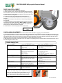
FORCE BLOWER Self-propelled Owner’s Manual
Patent #6,253,416 and other patents pending
F902SPS, F902SPH, F1302SPH, F1802SPV
BILLY GOAT FORCE BLOWER
Owner's Manual
Accessories
HOLD DOWN KIT
To secure blower for
transportation on
trailer floors.
P/N 440120
Part No 440314
SOLID FRONT TIRE
Solid flat-free front tire.
PARKING BRAKE
Effective and Easy to
use to prevent blower
from rolling.
CASTER KIT
For greater
maneuverability on
hard surfaces.
P/N 440279
P/N 440140
P/N 440293
1
Form No F060811E
FORCE BLOWER Self-propelled Owner’s Manual
CONTENTS
SPECIFICATIONS AND SOUND/VIBRATION
___
3
INSTRUCTION LABELS
4
PACKING CHECKLIST
5
ASSEMBLY
6
OPERATION
_ 7-8
MAINTENANCE
9
TROUBLESHOOTING___________________________
10
ILLUSTRATED PARTS LIST
11
PARTS LIST
12
Go to http://www.billygoat.com for French-Canadian translations of the product manuals.
Visitez http://www.billygoat.com pour la version canadienne-française des manuels de produits
Part No 440314
2
Form No F060811E
FORCE BLOWER Self-propelled Owner’s Manual
Specifications
F902SPS
F902SPH
F1302SPH
F1802SPV
9.0 HP (6.6kW)
9.0 HP (6.6kW)
13.0 HP (9.6kW)
18 HP (13.42kW)
Engine: Model
EX270D50021
GX270K1QA2
GX390K1QAA2
3564420224E9
Engine: Type
SUBARU OHC
HONDA OHV
HONDA OHV
B & S VANGUARD
Engine: Fuel Capacity
6.4 qt. (6.1L)
6.3 qt. (6.0L)
6.5 qt. (6.1L)
9 qt. (8.52L)
Engine: Oil Capacity
1.05 qt. (1.0L)
1.16 qt. (1.1L)
1.16 qt. (1.1L)
1.75 qt. (1.66L)
Total Unit Weight:
141 # (64 Kg)
152 # (68.9 Kg)
167 # (75.7 Kg)
182 # (82.6 Kg)
58"(1.43m)
58"(1.43m)
58"(1.43m)
58"(1.43m)
Overall Width
29.25” (0.74m)
29.25” (0.74m)
29.25” (0.74m)
29.25” (0.74m)
Overall Height
45" (1.14m)
45" (1.14m)
45" (1.14m)
45" (1.14m)
107dB(a) @3340
rpm
109dB(a) @ 3660
rpm
110dB(a) @ 3640 rpm
117dB(a)
87dB(a) @ 3340 rpm
89dB(a) @ 3660 rpm
90dB(a) @ 3640 rpm
97dB(a)
Engine: HP
Overall Length:
In compliance with 2000/14/EEC
standards
Sound at Operator’s ears
Vibration at operator position
2
.96 g (9.44 m/s )
2
2
1.05 g (10.30 m/s )
.81 g (7.96 m/s )
2
1.2 g (11.9 m/s )
SOUND
117 dB
SOUND LEVEL 97 Db(a) at Operators Position
Sound tests were conducted in accordance with 2000/14/EC, as well as ISO 11094, and were performed on 12-12-2006 under the conditions
listed below.
Sound power level listed is the highest value for any model covered in this manual. Please refer to serial plate on the unit for the sound
power level for your model.
General Conditions:
Temperature:
Wind Speed:
Wind Direction:
Humidity:
Barometric Pressure:
Sunny
o
o
40.4 F (4.7 C)
6.1 mph (9.9kph)
Southwest
93.6%
30Hg (101.85kpa)
VIBRATION DATA
2
VIBRATION LEVEL 1.2g (11.9m/s )
Vibration levels at the operator’s handles were measured in the vertical, lateral and longitudinal directions using calibrated vibration test
equipment. Tests were performed on 12-13-2006 under the conditions listed below.
General Conditions:
Temperature:
Wind Speed:
Wind Direction:
Humidity:
Barometric Pressure:
Part No 440314
Sunny
o
o
57.2 F (14.3 C)
11.8 mph (19.1kph)
South
46.4%
30.1Hg (101.96kpa)
3
Form No F060811E
FORCE BLOWER Self-propelled Owner’s Manual
INSTRUCTION LABELS
The labels shown below were installed on your BILLY GOAT ® FORCE Blower. If any labels are damaged or
missing, replace them before operating this equipment. Item numbers from the Illustrated Parts List and part
numbers are provided for convenience in ordering replacement labels. The correct position for each label may be
determined by referring to the Figure and Item numbers shown.
LABEL SPARK ARRESTOR
P/N 100252
LABEL READ OWNERS MANUAL
ITEM #44 P/N890301
LABEL EAR EYE BREATHING
ITEM# 45 P/N890254
DANGER FLYING DEBRIS
ITEM # 46 P/N 810736
START
LABEL CLUTCH ENGAGE
P/N 500176
LABEL EXPLOSIVE FUEL
ITEM # 43 P/N 400268
LABEL THROTTLE CONTROL
ITEM # 42 P/N 810656
LABEL OIL CHAIN
ITEM #119 P/N 830502
STOP
ENGINE LABELS
HONDA
SUBARU
READ OWNER’S MANUAL BEFORE OPERATION.
LIRE LE MANUEL D UTILISATEUR AVANT USAGE.
VOR INBETRIEBNAHME UNBEDINGHT BEDIENUNGSANLEITUNG DURCHLESEN.
NO UTILIZAR SINANTES NO HABER LEIDO EL MANUAL
OIL ALERT
WHEN OIL LEVELLOW,
ENGINE STOPS IMMEDIATELY.
HONDA MOTOR CO. , LTD. MADE IN JAPAN
BRIGGS AND STRATTON VANGUARD
Part No 440314
4
Form No F060811E
FORCE BLOWER Self-propelled Owner’s Manual
PACKING CHECKLIST
These items should be included in your carton. If any of these parts are missing, contact your dealer.
Your BILLY GOAT ® FORCE Blower was shipped in one carton, completely assembled except for the Upper Handle
Assembly and Front Diverter. Mounting hardware for the Upper Handle Assembly can be found in the parts bag.
READ all safety instructions before assembling unit.
TAKE CAUTION when removing the unit from the box as the Handle Assembly is attached to
the unit by cables.
PUT OIL IN ENGINE BEFORE STARTING
PARTS BAG &
LITERATURE ASSY
Warranty card P/N- 400972, Owner’s Manual P/N-440314, General Safety and Warnings Manual P/N100294, Declaration of Conformity P/N-440022, Handle Hardware-Items #10, #11, #74, #36, and #123
Boxing Parts Checklist
Front Air Diverter
(For F902S, F902H, and F1302H
models only)
Item#38
F9 MODELS P/N-440045-4
F13 MODELS P/N-440045-5
Handle Upper Assembly
Item #30 P/N-440035
Parts Bag & Literature Assy
P/N-440267
Honda 9 or 13 hp
Subaru 9 hp
B & S Vanguard 18 hp
Part No 440314
5
Form No F060811E
FORCE BLOWER Self-propelled Owner’s Manual
ASSEMBLY
1.Follow the steps in figures A and B, then securely tighten all hardware shown.
2.Connect spark plug wire.
Figure A
Figure B
The hardware for attaching the upper handle to the lower is in
the parts bag. Install upper handle (item 30), to preassembled
lower handle (item 28) by sliding the upper over and down the
outside of the lower handle. Using bolt (items #36 and 123),
washers (item #10) & lock nut (item #11) to install upper handle
to lower handle. Note: The Pigtail bolt should go on the side
that the pull start is on and the open end should be facing down.
Finish installing the other side of the upper handle assembly
using screw and lock nut provided.
The throttle control will be attached to the throttle arm on the
engine and wrapped around the engine for shipping. Unwrap
and secure throttle control (item #31) to upper handle with
screws (item #39). Screws will already be mounted in handle,
simply remove and use to mount the throttle control. Secure the
throttle cable and clutch cable with two Ty-wraps. The Aim-andTM
Shoot is not attached, you will need to unroll the cable and
attach the ball end to the lever and seat the cable end into the
hole on the saddle clamp, with the cable running through the
slot. The Clutch cable will also be wrapped up under the
machine. Route the cable under the axle and attach it by
removing the hitch pin and clevis pin and attaching it to the
clutch control lever. After it is attached pull on the cable and
slide it into the hole on the bracket so that it clicks into place. To
keep the cable from being damaged use three ty-wraps (item
74) to secure it to the handle as shown making sure that the
cable is not rubbing against the tire. Note: the cable should
be seated properly in the saddle and should follow the
contours of the handle.
Good routing
Two ½” open ended wrenches
Part No 440314
Bad routing
One 5/16 open ended wrench
6
Form No F060811E
FORCE BLOWER Self-propelled Owner’s Manual
OPERATION
DRIVE LEVER:
To engage the clutch for forward motion, simply hold down the clutch lever with your left hand while the engine is running,
this will cause the drive to engage and the machine will proceed to move forward.
Caution: It is not recommended to
“feather” the drive. The drive lever should be either fully engaged or fully disengaged. Failure to do so can cause
premature failure of the cone clutch in the transmission. This type of failure will void the manufacturer’s warranty.
BLOWING OPERATION
Your Billy Goat Force blower is equipped with an air director cone and the patented Aim-N-Shoot TM control lever to allow
the operator to direct the air stream up or down as required to assist in moving debris. This feature is extremely useful
when debris has piled up to the point that it cannot be blown any farther. The air stream can be directed upward to blow
the top of the debris pile over and allow the operator to continue moving more debris farther.
ADJUSTING AIR DIRECTOR
To adjust air direction, squeeze Aim-N-ShootTM control lever. When you want to blow debris at the same angle for an
extended period, choose a suitable position and use the finger controlled push button lock to lock the cone in position.
For operations that do not require the use of the Aim-N-ShootTM feature the manual adjustment knob, pictured below, can
be used to permanently lock the cone into position.
CAUTION: Be sure to release the knob when returning to using
the Aim-N-ShootTM.
DO NOT position director cone to where it will blow debris towards people, vehicles or other objects in vicinity. Flying
debris may damage, harm, or cause injury to people or objects in air flow range.
Manual Adjustment
knob
FRONT DIVERTER POSITIONING (F9 and F13 models only)
The removable front diverter adapter can be slipped inside the cone to direct the air stream forward. First turn off
engine, and then simply collapse and fold in the larger opening of the diverter and slide inside the cone and allow it to
expand. Then position to the desired angle by rotating the diverter. This option is extremely useful for cleaning out long
cracks in pavement or for cleaning under bushes, building overhangs or along curbs.
WARNING: Unit will be more difficult to control due to the air exiting the unit. Keep hands on the unit at all times when
using the front diverter. Please note that the Aim-N-ShootTM feature will not function when the Front Diverter is installed
Squeeze and fold
here
Part No 440314
Front diverter
7
Form No F060811E
FORCE BLOWER Self-propelled Owner’s Manual
MAINTENANCE
Periodic maintenance should be performed at the following intervals:
Maintenance Operation
Inspect for worn or damaged parts.
Every
Use
Daily or Every
5 Hours
Every 50
Hours
Every
100-150
Hours
z
z
Check for excessive vibration
Check belt/chain tightness
Every 25
Hours
z
z
Oil drive chain
z
Inspect Impeller for cracks or damage
z
Inspect for loose parts.
IMPELLER REMOVAL
1. Wait for engine to cool and disconnect spark plug.
2. Remove housing front cover, by removing (11) bolts and nuts, items #13 & #14, around outside of front
cover.
3. Remove impeller bolt (item #35), lock washer (item #71) and washer (item #34).
4. DO NOT pry on impeller. Pull on center hub area only of impeller. Using a penetrating oil can help loosen a
stuck impeller.
5. Reinstall new impeller in reverse order of removal.
6. Tighten impeller bolt. Torque impeller bolt (see parts list on page 15 for proper impeller bolt torque
specifications).
TIRE AIR PRESSURE
Check at regular intervals and maintain.
Front Tires - 24 Psi (165 kPa).
Rear Tires - 20 Psi (137 kPa).
BELT TENSION ADJUSTMENT
DO NOT ADJUST WHILE THE MACHINE IS RUNNING!
1. Wait for engine to cool and disconnect spark plug.
2. Loosen the nut (item 92) on the Idler pulley (item 93) but do not remove it. This should allow the pulley to slide left or
right. Once the pulley is at the proper distance to apply tension to the belt tighten the nut. Note: Do not place too much
tension on the belt, as it will cause premature failure.
3. Reattach the spark plug.
BELT REPLACEMENT
1. Wait for engine to cool and disconnect spark plug.
2.Follow the Impeller removal steps (2-5 on page 12).
3. Remove the four bolts (item 8) holding the back plate (item 4) to the
back housing (item 6).
4. Loosen the nut on the idler pulley and slide it to the right to relieve
tension on the belt.
5. Slip the belt (item 86) off the engine pulley and the transmission.
6 Replace the belt with a new one and slide the Idler pulley to put
proper tension on the belt. Note: Do not place too much tension on the
belt, as it will cause premature failure.
7. Reassemble the machine in reverse order. Note: You will need to
replace the Impeller bolt and torque to the proper specifications see
page 16, DO NOT use the old one.
Idler Pulley
8. Reconnect spark plug wire.
Part No 440314
8
Form No F060811E
FORCE BLOWER Self-propelled Owner’s Manual
DRIVE CHAIN REPLACEMENT
1. Wait for engine to cool and disconnect spark plug.
2. Place a block of wood, or another object that will support and steady
the unit under the axle on the side of the machine you will be working on.
3. Remove the two screws (item 103) holding the chain guard (item 104)
and then remove the chain guard.
4. Loosen the two nuts (item 98) holding the bearing (item 97).
5. Remove the retaining ring holding the wheel on and then slide the
wheel off.
6. Replace the chain (item 105). Remove the old chain by walking it off
the sprockets.
7. Position the bearing so that it applies the proper tension to the chain
and tighten the nuts holding the bearing Note: DO NOT over tighten the
chain, as this will cause premature failure. Likewise if the chain is too
loose it will come off when the drive is engaged.
8. Reassemble the machine using steps 1-4 in reverse order.
Loosen these
nuts
CLUTCH CABLE ADJUSTMENT
1. With the machine off, loosen the two nuts on the end of the clutch cable (item 111) going in to the transmission.
2. By moving the position up or down on the threads it will change the tension on the clutch lever (item 113). Note: Do not position it too
high on the threads as this could cause the drive not to engage. Likewise, if it is placed too low the drive may stay permanently engaged.
The optimum setting is to remove any slack in the clutch cable when disengaged. The travel of the clutch control will apply the correct
spring force on the cone clutch. Once the desired position is in place tighten the nuts securely.
3. Start the machine and check the operation. If the drive cable is not engaging properly, shut the machine off and reposition the nuts on
the cable to tighten the drive cable.
TROUBLESHOOTING
P r o b le m
A b n o r m a l v ib r a t io n .
P o s s ib le C a u s e
· L o o s e o r o u t o f b a la n c e im p e lle r .
· D e b r is in im p e lle r .
· L o o s e e n g in e .
S o lu tio n
· C h e c k im p e lle r a n d r e p la c e if r e q u ir e d .
· C le a r d e b r is w ith c o m p r e s s e d a ir o r a
b a c k p a c k b lo w e r ( s e e b e lo w p ic tu r e s ) . *
· C h e c k e n g in e .
E n g in e w ill n o t s t a r t.
· E n g in e n o t in f u ll c h o k e p o s itio n .
· O u t o f g a s o lin e o r b a d , o ld g a s o lin e .
· C h e c k c h o k e p o s itio n .
· C h e c k g a s o lin e .
· S p a r k P lu g w ir e d is c o n n e c te d .
· G a s v a lv e o f f .
· D ir ty a ir c le a n e r .
· C o n n e c t s p a r k p lu g w ir e .
· T u r n o n g a s v a lv e .
· C le a n o r r e p la c e a ir c le a n e r . C o n ta c t a
q u a lif ie d s e r v ic e p e r s o n .
· C o n t a c t a n e n g in e s e r v ic in g d e a le r f o r
e n g in e p r o b le m s .
· C le a n d e b is
· A p p ly s ilic o n e b a s e d lu b r ic a n t to
p iv o t p o in ts
· L o o s e n m a n u a l a d ju s tm e n t k n o b
· Loosen nut
E n g a g e d r iv e le v e r
C h e c k d r iv e b e lt
C h e c k d r iv e c h a in
C h e c k d r iv e c a b le ( s e e p a g e 1 3 )
E n g in e is lo c k e d , w ill n o t p u ll
o v e r.
TM
le v e r s tic k in g
A im - N - S h o o t
· E n g in e p r o b le m .
N o s e lf p r o p e llin g
D r iv e le v e r n o t e n g a g e d
D r iv e b e lt w o r n o r b r o k e n
D r iv e c h a in o f f th e s p r o c k e ts
D r iv e c a b le is o u t o f a d ju s tm e n t
Im p r o p e r d r iv e c a b le a d ju s tm e n t, o r
c a b le is k in k e d
S e lf P r o p e lle d d r iv e w ill n o t
r e le a s e
N o is y o r b r o k e n c h a in
· D e b r is s tu c k a r o u n d c o n e
· C o n e a d ju s tm e n t k n o b to o tig h t
· A d a p to r m o u n t n u t ( it e m 3 8 ) to o
tig h t
N o c h a in o r lu b r ic a tio n
C h a in te n s io n
C h e c k t h e d r iv e c a b le ( s e e p a g e 1 3 )
L u b r ic a t e c h a in
C h e c k d r iv e c h a in ( s e e p a g e 1 3 )
*Using compressed air, or a Backpack blower, you can
loosen or free debris easily from the impeller and housing,
which can cause wear and tear on the machine. You can
manually remove debris by taking off the front housing.
Note: Always disconnect the spark plug when servicing.
Part No 440314
9
Form No F060811E
FORCE BLOWER Self-propelled Owner’s Manual
ILLUSTRATED PARTS LIST
Part No 440314
10
Form No F060811E
FORCE BLOWER Self-propelled Owner’s Manual
PARTS LIST
F1302SPH
F902SPH
F902SPS
F1802SPV
ITEM NO. DESCRIPTION
PART NUMBER QTY. PART NUMBER QTY. PART NUMBER QTY. PART NUMBER
1
ENGINE 13 HP HONDA GX390
440018
1
ENGINE 9 HP HONDA GX270
430287
1
ENGINE 9 HP HORZ SUBARU OHC
430413
1
ENGINE 18 VANGUARD
812240
2
BASE ENGINE WA FSP
440244-S
1
440244-S
1
440244-S
1
440244-S
3
GUARD BELT UPPER FSP
440209
1
440209
1
440209
1
440209
4
PLATE REINFORCE HOUSING
440010
1
440010
1
440010
1
440010
5
HOUSING FRONT MOLDED
440023
1
440023
1
440023
1
440023
6
HOUSING BACK MOLDED
440024
1
440024
1
440024
1
440024
7
WASHER LOCK 3/8 S/T MED
8177012
4
8177013
5
8177013
5
8177013
8
SCREW CAP 3/8-16X 2 ZP
8041054
4
8041054
4
8041054
4
8041054
9
ROD HAND STOP
440057
1
440057
1
440057
1
440057
10
WASHER 5/16 FLATWASHER Z/P
8171003
14
8171003
14
8171003
14
8171003
11
NYLON INSERT LOCKNUT 5/16-18
8160002
11
8160002
11
8160002
11
8160002
12
SCREWCAP 5/16-18 X 1.75 ZP
8041031
4
8041031
4
8041031
4
8041031
13
SCREWCAP 1/4-20 x 1 1/2
8041008
11
8041008
11
8041008
11
8041008
14
NUT FLANGE 1/4-20
900455
15
900455
15
900455
15
900455
15
WHEEL & TIRE 13" X 5" PNEUMATIC SPROCKE
440219
2
440219
2
440219
2
440219
16
RING RETAINING 3/4
850230
2
850230
2
850230
2
850230
17
SCREW SM 1/4" X 3/4" TYPE AB HX WF
8122082
7
8122082
7
8122082
7
18
WHEEL ASSY 10 " PNEUMATIC
400295
1
400295
1
400295
1
400295
19
SPACER FRONT AXLE
440220
1
440220
1
440220
1
440220
20
SPACER LH WHEEL FRONT
440224
1
440224
1
440224
1
440224
21
SPACER RH WHEEL FRONT
440221
1
440221
1
440221
1
440221
22
SCREWCAP 1/2-13 x 9 1/2"
8041240
1
8041240
1
8041240
1
8041240
23
WASHER FLAT 1/2" SAE
8172011
2
8172011
2
8172011
2
8172011
24
WASHER W/BOLT WA
440075
1
440075
1
440075
1
440075
25
KNOB 3/8-16 SOLID HUB
811230
1
811230
1
811230
1
811230
26
WASHER 2.25 OD x .515 ID x .134 ZP
610308-P
1
610308-P
1
610308-P
1
610308-P
27
BRACKET HOLDER WA
440240
1
440240
1
440240
1
28
HANDLE LOWER
440034
1
440034
1
440034
1
440034
29
NYLON INSERT LOCKNUT 1/2-13LT WT TH ZP
8161044
1
8161044
1
8161044
1
8161044
30
HANDLE UPPER
440035
1
440035
1
440035
1
440035
31
CONTROL THROTTLE
440013
1
440013
1
440013
1
440013
32
CABLE THROTTLE CONTROL
440014
1
440014
1
440014
1
440178
33
NUT LOCK 3/8-16 LT WT THIN ZP
8161042
3
8161042
3
8161042
3
8161042
34
WASHER 1.5 O.D.X 0.45 I.D. X 0.5
440176
1
440176
1
440176
1
440176
35
440151
1
SCREWCAP 3/8-24 X 3.5 GR. 8 (38 +/-2 ft-lbs.)
440150
1
440150
1
SCREWCAP 7/16-20 X 3.5 GR.8 (60 +/-2 ft-lbs)
8042062
SCREWCAP 3/8-24 X 4 GR.8 (38 +/-2 ft-lbs)
36
SCREWCAP 5/16"-18 X 2" ZP
8041032
1
8041032
1
8041032
1
8041032
37
DIRECTOR CONE 5"
440044-S
1
DIRECTOR CONE 4"
440046-S
1
440046-S
1
DIRECTOR CONE 6"
440170-S
38
DIVERTOR FRONT
440045-5
1
440045-4
1
440045-4
1
39
SCREW SM #10-24X1/2" DRILL POINT
8122064
2
8122064
2
8122064
2
8122064
40
IMPELLER ASSEMBLY 17"
440236
1
440236
1
440236
1
IMPELLER SERVICE ASSY FORCE 18HP
440162
41
GRILL FRONT BLOWER
440067-1-S
1
440067-1-S
1
440067-1-S
1
440171-S
42
LABEL THROTTLE CONTROL
810656
1
810656
1
810656
1
810656
43
LABEL FUEL EN/SP
100261
1
100261
44
LABEL READ
890301
1
890301
1
890301
1
890301
45
LABEL EAR EYE BREATHING
890254
1
890254
1
890254
1
890254
46
LABEL DANGER FLYING DEBRIS
810736
1
810736
1
810736
1
810736
48
LABEL FORCE
440269
1
440269
1
440269
1
440269
49
HANDLE ASSY
440104
1
440104
1
440104
1
440104
50
KEY 1/4" SQ x 3 1/4
9201128
1
9201128
1
9201128
1
KEY 1/4" SQ x 2 3/4
9201130
51
SCREWCAP 1/4-20 X 1" HCS ZP
8041006
52
WASHER FLAT 1/4
8171002
53
NUT LOCK 1/4"-20 HEX ZP
8160001
1
8160001
1
8160001
1
8160001
54
HANDLE DIVERTER FORCE
440119
1
440119
1
440119
1
440119
55
PIN LATCH DIVERTER
440118
1
440118
1
440118
1
440118
56
SPRING COMPRESSION 0.281 X 0.88
440129
1
440129
1
440129
1
440129
57
RING RETAINING .122 DIA
440125
1
440125
1
440125
1
440125
58
SADDLE UPPER DIVERTER
440115
1
440115
1
440115
1
440115
59
PLATE LOCK DIVERTER
440116
1
440116
1
440116
1
440116
60
SCREW PLASTITE #6-19 X 5/8"
440126
1
440126
1
440126
1
440126
61
SADDLE LOWER DIVERTER
440114
1
440114
1
440114
1
440114
62
SCREW PLASTITE #10-14 X 1"
440132
2
440132
2
440132
2
440132
63
PIN PIVOT DIVERTER CONTROL
440123
1
440123
1
440123
1
440123
64
RING RETAINING 5/16
430327
1
430327
1
430327
1
430327
Part No 440314
11
QTY.
1
1
1
1
1
1
4
4
1
14
11
2
11
15
2
2
1
1
1
1
1
2
1
1
1
1
1
1
1
1
3
1
1
2
1
2
1
1
1
1
1
1
1
1
1
1
5
5
6
1
1
1
1
1
1
1
1
2
1
1
Form No F060811E
FORCE BLOWER Self-propelled Owner’s Manual
PARTS LIST
ITEM NO.
65
66
67
68
69
70
71
72
73
74
75
76
77
78
81
82
83
84
85
86
87
88
89
90
91
92
93
94
96
97
99
100
101
102
103
104
105
108
109
111
113
114
115
117
118
119
120
121
122
123
125
F1302SPH
F902SPH
F902SPS
F1802SPV
DESCRIPTION
PART NUMBER QTY. PART NUMBER QTY. PART NUMBER QTY. PART NUMBER
CABLE ASSY
440117
1
440117
1
440117
1
440117
DIVERTER PIVOT ADAPTOR
440121
1
440121
1
440121
1
440121
SPRING EXTENSION 0.468 X 5.25
440130
1
440130
1
440130
1
440130
BRACKET DIVERTER FORCE
440212
1
440212
1
440212
1
440212
PIN CLEVIS 1/4 X 3/4
440124
2
440124
2
440124
2
440124
HITCH PIN CLIP .051 X 3/4"
440193
2
440193
2
440193
2
440193
WASHER LOCK 3/8 S/T MED
8177012
1
8177012
WASHER LOCK 7/16 S/T MED
8177013
1
8177013
1
ADAPTOR MOUNT WA
440122
1
440122
1
440122
1
440122
GRIP 1-1/4" ID x 9.5" LONG
440146
2
440146
2
440146
2
440146
TY-WRAP
900407
5
900407
5
900407
5
900407
WASHER .765 ID X 1.25 OD X0.6"
850238
2
850238
2
850238
2
850238
FORCE WHEEL BEARING .751 ID
440055
2
440055
2
440055
2
440055
GUARD MANIFOLD
812243
GUARD MUFFLER
812242
ROLL PIN
8195096
1
8195096
1
8195096
1
8195096
SPACER REAR WHEEL SP
440225
2
440225
2
440225
2
440225
PLUG
791056
2
791056
2
791056
2
791056
CARRIAGE BOLT 3/8"-16 X 1 3/4" ZP
8024061
5
8024061
5
8024061
5
8024061
SPACER ENGINE FACE
440174
1
440174
1
440174
1
440174
BELT 3L29
440215
1
440215
1
440215
1
440215
SPACER HUB 1" ID X 1.25" W/PULLEY
440213
1
440213
1
440213
1
SPACER HUB 1" ID X 1.25" W/PULLEY FSP18
440214
CARRIAGE BOLT 3/8-16 X 5" ZP
8024161
1
8024161
1
8024161
1
8024161
TUBE SPACER .625" OD X .357 LONG
440228
1
440228
1
440228
1
440228
GUARD BELT LOWER FSP
440210
2
440210
2
440210
2
440210
SCREW PLASTITE 1/4-10 X 3/4 HWH ZP
840082
6
840082
6
840082
6
840082
SCREW SM 1/4" X 1" DRILL PT
430208
PULLER V IDLER 2.5
510137
1
510137
1
510137
1
510137
WASHER 1.00" OD X .380 SQ HOLE
440227
1
440227
1
440227
1
440227
CARRIAGE BOLT 1/4"-20 X 3/4"
8024021
4
8024021
4
8024021
4
8024021
BEARING 1/2" STEEL PRESSED HOUSING
891025
2
891025
2
891025
2
891025
KEY WOODRUFF 1/8" X 1/2"
510180
2
510180
2
510180
2
510180
SPROCKET 8 TOOTH
891022
2
891022
2
891022
2
891022
RETAINING RING 1/2"
350146
2
350146
2
350146
2
350146
SPROCKET 32T #43 1.594 BORE
440218
2
440218
2
440218
2
440218
SCREW SELF TAP 1/4"-20 X 5/8"
890359
4
890359
4
890359
4
890359
CHAIN GUARD LH
440206-S
1
440206-S
1
440206-S
1
440206-S
CHAIN GUARD RH
440207-S
1
440207-S
1
440207-S
1
440207-S
CHAIN #43X44 PITCHES
440217
2
440217
2
440217
2
440217
TRANS SINGLE SPEED W/CLUTCH
440216
1
440216
1
440216
1
440216
WASHER 3/8" SAE
8172009
2
8172009
2
8172009
2
8172009
CLUTCH CABLE FORCE SP
440243
1
440243
1
440243
1
440243
CLUTCH CONTROL ARM
440277
1
440277
1
440277
1
440277
CLUTCH CONTROL BRACKET
440245
1
440245
1
440245
1
440245
GRIP CLUTCH CONTROL FSP
440242
1
440242
1
440242
1
440242
SPARK ARRESTOR LABEL
100252
1
100252
1
100252
1
100252
SPRING LEVER GZ
610429
1
610429
1
610429
1
610429
LABEL OIL CHAIN
830502
2
830502
2
830502
2
830502
LABEL DANGER
900327
2
900327
2
900327
2
900327
NUT LOCK 5/16-24 SER HEX WSHR FLNG
440274
8
440274
8
440274
8
440274
LABEL CLUTCH DRIVE
500176
1
500176
1
500176
1
500176
EYEBOLT PIGTAIL 5/16"-18 X 1 1/4"
440280
1
440280
1
440280
1
440280
LABEL MADE IN U.S.A.
520116
1
520116
1
520116
1
520116
Part No 440314
12
QTY.
1
1
1
1
2
2
1
1
2
5
2
2
1
1
1
2
2
5
1
1
1
1
1
2
6
2
1
1
4
2
2
2
2
2
6
1
1
2
1
2
1
1
1
1
1
1
2
2
8
1
1
1
Form No F060811E