1
OWNERS MANUAL
INSTALLATION AND OPERATING INSTRUCTIONS
REPAIR PARTS LIST
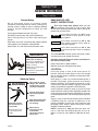
Self Prime Frame Mounted
Centrifugal Pump
B4ZRKS
B2ZRKL
B3TRKS
B2XRKS
Direct Coupling Drive/
Belt Driven/Hydraulic Drive
IMPORTANT
For best possible performance and continuous, satisfactory operation,
read these instructions before installing your new pump.
Should service be required, this manual can be a valuable guide.
It should be kept near the installation for ready reference.
Record nameplate data from pump on blank nameplate inside this
manual for future reference.
Berkeley Pumps / 293 Wright Street / Delavan, WI 53115
F00633 (Rev. 4/18/05)
Safety First
General Information
Pump Location
General Safety
Do not allow pump, piping, or any other system
component containing water to freeze. Freezing may
damage system, leading to injury or flooding. Allowing
pump or system components to freeze will void
warranty.
Pump approved liquids only with this pump.
Periodically inspect pump and system components.
Wear safety glasses at all times when working on
pumps.
Keep work area clean, uncluttered and properly lighted;
store properly all unused tools and equipment.
Keep visitors at a safe distance from the work areas.
WARNING
Rotating parts. Can catch
hands, feet, or clothing.
Stay clear of equipment and
keep shields in place while
pump is running.
Stop motor or engine before
servicing pump.
Read owner’s manual before
using equipment.
Electrical Safety
WARNING
Wire motor for correct
voltage. See “Electrical”
section of this manual
and motor nameplate.
Ground motor before
connecting to power
supply.
Hazardous voltage.
Can shock, burn, or
cause death.
Ground pump before
connecting to power
supply.
Page 2
Meet National Electrical
Code and local codes
for all wiring.
Follow wiring
instructions in this
manual when
connecting motor to
power lines.
READ AND FOLLOW
SAFETY INSTRUCTIONS!
This is the safety alert symbol. When you see
this symbol on your pump or in this manual, look
for one of the following signal words and be alert to the
potential for personal injury:
warns about hazards that will cause
serious personal injury, death or major
property damage if ignored.
warns about hazards that will or can
cause serious personal injury, death or
major property damage if ignored.
warns about hazards that will or can
cause minor personal injury or property
damage if ignored.
The label NOTICE indicates special instructions which
are important but not related to hazards.
Carefully read and follow all safety instructions in
this manual and on pump.
Keep safety labels in good condition.
Replace missing or damaged safety labels.
LOCATION:
Locate the pump as near to the water source as
practical. Make the suction pipe run short and straight
with as few pipe fittings as possible to keep total friction
loss to a minimum.
Install pump in a clean, dry and well drained location if
possible and protect against moisture and adverse
weather conditions. Pump should be located on a level,
hard surface to prevent shifting or tipping. Locate to be
readily accessible for inspection and maintenance.
Careful attention should be taken to assure that Net
Positive Suction Head Available (NPSHA) exceeds Net
Positive Suction Head Required (NPSHR) by the pump
or reduced performance and severe pump damage may
result.
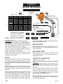
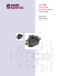
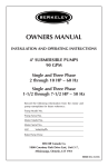
Figure 1, Page 3, illustrates where these terms (NPSHA
/ NPSHR) originate, and how to determine if the
pumping conditions at which you want to operate meet
the proper criteria. When in doubt, consult your nearest
Berkeley Professional Dealer.
NOTE: If pump site is 1000 feet above sea level, subtract 1.2 feet from the NPSHA equation and an additional 1.2 feet for each additional 1000 feet of elevation.
F00633
Installation
General Information
EXAMPLE
ONLY
NPSHR at this point
= 8 Feet
NPSHR at this point
= 9 Feet
B4ZRKS
9.5 Feet total friction loss
@ 450 Gallons per minute.
30
20
10
0
10.5 Feet total friction loss
@ 550 Gallons per minute.
450 GPM
550 GPM
Static Lift = 9.0 Feet
Total Friction Loss = 9.5 Feet
9.0 Feet
10.5 Feet
19.5 Feet
150
TDH
2000 RPM
100
NPSHA
NPSH in Feet
NPSHR
Total = 18.5 Feet
Theoretical static
lift of centrifugal
pump at sea level = 34.0 Feet
Safety Factor
- 6.0 Feet
50
0
0
100
200
300
400
500
600
Gallons Per Minute
700
A Model B4ZRKS operating at 450 GPM
with 95 Feet of Head has a NPSHR of.......... 8 Feet
at that point on the performance curve.
FIGURE 1
A Model B4ZRKS operating at 550 GPM
with 85 Feet of Head has a NPSHR of.......... 9 Feet
at that point on the performance curve.
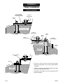
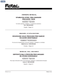
FOUNDATION: Refer to illustration on Page 4.
Heavy weights; risk of bodily harm due
to crushing. Use care and proper lifting equipment
when handling pump for installation. Size and weight of
some units will require hoists for safe handling.
Pump should be set on a concrete foundation which is
sufficiently substantial to absorb vibration and which
provides a permanent and rigid support.
When properly positioned, the unit will be level, and the
suction and discharge openings of the pump will be
aligned with system piping.
PIPING:
System piping should be at least one commercial pipe
size larger than pump connections and flow velocity
should not exceed eight (8) feet per second. Suction and
discharge pipes must be naturally aligned with pump
connections.
NOTICE: Misalignment of piping with pump case or
excessive pipe strain can cause distortion of pump
components resulting in rubbing, breakage and reduced
pump life.
Insure that piping is supported in a manner that prevents
the exertion of force on pump connections. This can be
checked by the following procedure. With the pump shut
down, remove pipe flange bolts. If the mating flanges
come apart or shift, misalignment is present and causing
pressure on the connections. Adjust pipe supports until
F00633
9 Feet
Static Lift
Practical Limit = 28.0 Feet
Minus 18.5 Feet
OK
CAVITATION
28.0 Feet
19.5 Feet
NPSHA = 9.5 Feet
NPSHA = 8.5 Feet
2111 1095
flanges mate without any force. This procedure can be
done throughout piping system.
SUCTION PIPING:
Refer to illustrations on Page 8 through Page 11 for
recommended and not recommended practices in
suction connections.
DISCHARGE PIPING:
Refer to illustrations on Pages 12 through 13 for
recommended and not recommended practices in
discharge connections.
ELECTRICAL CONNECTION:
If electric motor is used.
NOTE: All wiring should be done by a qualified
electrician.
Hazardous voltage. Can shock, burn, or
cause death. Disconnect power to pump before
servicing.
Check voltage and phase stamped on pump motor
nameplate before making wiring connections to
electrical system. Be sure they agree with your electric
current supply. They MUST be the same. If in doubt,
check with your local power company.
Refer to illustration on Page 7 for minimum recommended pumping panel components that help safeguard
your pump during operation.
Page 3
Installation
Pump Foundation
Typical Installations
1/2" or thicker
Sole Plate tapped
for hold down bolts
Pump or
Motor Frame
Anchor
Bolts
;;;;;;;;
@@@@@@@@
;;;;;;;;
@@@@@@@@
;;;;;;;;
@@@@@@@@
;;;;;;;;
@@@@@@@@
ge
ina
Dra
Concrete Foundation
Pump or
Motor Frame
Shims
for alignment
Steel
Channel
Anchor
Bolt
;;;;;
;;
;;
;;;;;
;;
;;
;;;;;;;;
@@@@@@@@
Tack
Weld
Wedges
Various Heights
Grout
;;;;;;;;
@@@@@@@@
;;;;;;;;
@@@@@@@@
;;;;;;;;
@@@@@@@@
Grout
Dam
Dra
Concrete
Foundation
Pump and Motor
Base
;;;;;;;
@@@@@@@
;;;;;;;
@@@@@@@
;;;;;;;
@@@@@@@
;;;;;;;
@@@@@@@
inag
e
Shims
ge
ina
Dra
Concrete
Foundation
• There are several types of permanent pump/
foundation installations in use. Those pictured above
are typical.
• If grout is used, top of concrete should be left rough
to provide a good bonding surface.
• Foundation should slope away from pump to prevent
liquid from pooling.
1300 1094
Page 4
F00633
Installation
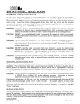
Direct Coupling Drive
Shaft Alignment
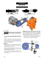
Table I
Distance from Centerline
1.00 inch
2.00 inches
3.00 inches
4.00 inches
Maximum Allowable T.I.R.
0.035 inches
0.070 inches
0.105 inches
0.140 inches
Straight Edge
Centerline
Fine Alignment
Caliper
"B"
Parallel
"A"
Angular
Course Alignment
2112 1095
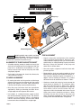
Rotating shaft can catch and trap
clothing or body. Coupling guard must
ALWAYS be in place when pump is running. Coupling
guard shown in phantom for pictorial clarity.
ALIGNMENT OF PUMP AND MOTOR SHAFT
• A flexible coupling (except for double universal joint
shaft) will not compensate for misalignment. After the
pump unit is fastened on the foundation, it is necessary to see that the shafts of the pump and motor
are properly aligned.
• Each motor and pump foot should be shimmed to
avoid shifting or soft foot.
COURSE ALIGNMENT
• By moving the entire unit, bring suction and discharge
openings of the pump into alignment with the system
piping. Install piping at this time. Pipes should align
naturally with the pump (see Installation Section).
• Bring the pump and motor shaft into approximate
alignment by shifting or shimming the motor. Use a
straight edge to check alignment of the shafts.
• Use calipers, or a wedge thickness gauge to check
the distance between coupling halves. The distance
between halves should be equal at 90 degree
intervals around the coupling, and the shafts should
be concentric when checked with a straight edge.
F00633
FINE ALIGNMENT
• Angular and parallel misalignment of the coupling
may be corrected simultaneously. Maintain a separation between coupling halves, per manufacturer’s
specifications, to avoid preloading of pump and motor
bearings. Clamp dial indicators to the pump and
motor shaft as shown above.
• Start with angular alignment and finish check with
parallel alignment.
• Rotate both the shaft and coupling together by hand.
Note the total indicated runout shown on indicator “A”.
The maximum allowable angular misalignment is 1
degree. Limits of reading on indicator “A” at various
distances from shaft centerline are shown in Table I.
• Continue to rotate both shafts by hand and note the
runout shown on indicator “B”. The maximum allowable total indicated runout is .005 inches. Should
either angular or parallel misalignment exceed the
value shown, shift or shim the motor until misalignment is within the allowable limits shown. Do not
move pump unless absolutely necessary. When
shimming, be sure that all feet on the pump and
motor are equally supported to avoid strains on the
castings when the hold down bolts are tightened.
Page 5
Installation
Belt Drive
Alignment/Proper Belt Tension
B
B
A
Incorrect
Incorrect
A
Centerline - A of each shaft and pulley must
be parallel for proper alignment.
Centerline - B represents center of belt and
pulley.This centerline must be straight for
proper alignment.
Centerline
A
B
B
2113 1095
Centerline
A
Drive belt can catch and trap clothing
or body. Belt guard must ALWAYS be in
place when pump is running. Belt guard is not shown for
pictorial clarity.
NOTICE: Belts must be tight enough to prevent slipping during operation. Loose belts result in early belt
failure and reduced performance. However, excessive
tightness of belts will result in overheating of the belts
and excessive bearing load in the pump and driver.
• Drive and pump shaft centerlines (A) must be parallel
as shown. Belt centerlines (B) must be straight as
shown.
• Most Vee-belts will stretch slightly after initial
installation. After a short period of operation, recheck belt tension and adjust as necessary.
ALIGNMENT
• When installing belts, move the driver toward the
pump to allow belts to be placed on pulley. Then,
move the driver away from pump to obtain proper belt
tension as described below.
Center of span.
Slack should not be more
than one belt thickness.
TENSION
• Multiple belt spans must be equal tension in all belts.
Proper belt tension varies with the size of belt being
used, however a general rule is:
Belts are properly tensioned when one belt can be
depressed one belt thickness at the center of the
span when pressing with thumb.
Another method is that a properly tensioned belt can
be rotated (twisted) one-quarter revolution at the
center of span.
Page 6
A
1423 1294
Proper tension allows onequarter revolution of belt.
A
View
A-A
F00633
Installation
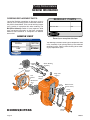
Electric Motor / Hydraulic Motor
p
p
g p
prior to
installation.
Minimum recommended
components
to protect your pump during
1.
Contactor
operation. Check all local electrical codes prior to installation.
❶ Contactor
❷ Lightning
Arrestor
❸ Loss of Prime
Protection
❹ Fuseable
Disconnect
❺ Starter
2. Lightning Arrestor
3. Loss of Prime Protection
4. Fuseable Disconnect
5. Starter
Incoming Power
1
4
2
5
3
L1
L2
L3
AMP TIME
AUTO
OFF
HAND
START
2116 1195
NEMA3R
3REnclosure
Enclosure
NEMA
Protect Your Investment
Installation
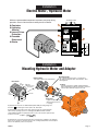
Mounting Hydraulic Motor and Adapter
Hydraulic Motor
(See Motor Detail for fit requirements)
Motor Detail
.38
Shoulder
.56
Bolt
Clearance
Mounting Bracket
Fits on bearing bracket in place of outer bearing
cap. Supports Hydraulic Motor and maintains exact
shaft alignment.
Coupling
Precision machined to fit SAE standard Hydraulic
Motor Shaft Spline.Coupling is installed on shaft and
locked in place with drive key and set screw.
1.625
Flange Face to
end of shaft
.875 O.D.
3.998
4.000
5.750
Pump Shaft
Length and diameter factory
machined for precision fit
to coupling.
Hydraulic Motor must have an SAE Standard (SAE J744C) mounting flange and
shaft size B , with 30 degree involute spline, 13T, 16/32 pitch.
Hydraulic Motor must produce the Torque required to drive the centrifugal pump
at the desired operating speed. For centrifugal pump GPM and TDH, read the
required RPM and BHP from pump performance curve, and calculate required torque
in Lbs-Ft, as follows:
(5252) x (BHP)
Torque =
(RPM)
2237 0196
Hydraulic Motor selected must match with the flow and pressure capability of the hydraulic
power source system. The operating speed of the centrifugal pump will be controlled by the
valves in the hydraulic power source system.
F00633
Page 7
Installation
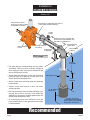
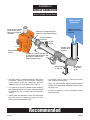
Suction Connection
Suction Lift
Pump driven by remote
power source, direct coupling
or pulley/belt connection.
Short length of straight pipe after reducer.
( 2 times pipe diameter minimum )
Suction
Gauge
Straight run, short as possible but
at least 6 times pipe diameter ("D")
after elbow to stabilize flow.
2114 1095
See foundation
section.
Standard or long
radius elbow.
Eccentric Reducer
flat side up.
Support pipe
as required
Slope upward
to pump.
NOTICE: All connections
must be air tight.
As close
as possible
• Use pipe, tubing, or reinforced hose to make suction
connection. Hose must have sufficient strength to
resist collapse under the pressure differential that
occurs while pump is running.
• Suction pipe size should be at least one commercial
pipe size larger than opening of pump inlet. Flow
velocity should not exceed 8 ft./sec.
Pipe diameter ("D")
4 x "D"
minimum
• Suction screen must screen out solids that could clog
pump impeller.
• Suction screen area must be at least four times
suction pipe area.
• Net Positive Suction Head Available (NPSHA) must
exceed Net Positive Suction Head Required
(NPSHR) by the pump or reduced performance and
severe pump damage may result.
1 x "D" minimum
from bottom
• All suction piping must have continuous rise to the
pump suction inlet. A 1/4 inch per foot minimum slope
is recommended.
Strainer / Foot Valve
To keep debris from entering
pump suction and to maintain
pump prime after shut-off.
Recommended
Page 8
F00633
Installation
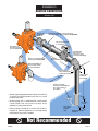
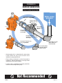
Suction Connection
Suction Lift
Do not use
Concentric
Reducer.
Concentric Reducer causes high spots
along the suction line resulting in air pockets.
Do not install valves
in suction line.
No support or
uneven mounting
not recommended.
Unsupported
pipe causes
excessive stress
on pump and fittings.
Excess use of pipe fittings
means potential air leaks.
Long run
not recommended
Elbow immediately in
front of pump intake
not recommended.
Pipe diameter
("D") undersized
reduces performance
High suction
lift should
be avoided.
Vortex caused by
insufficient submergence
may cause pump to
lose prime.
• Suction pipe sloping downward to pump inlet will trap
air which will reduce performance and may cause
pump to lose prime.
• Suction piping that is undersized will create excess
friction losses that may cause cavitation and a
reduction in pump performance.
• Excess fittings and bends in suction line results in
trapped air, reduced performance, and high friction
losses which may cause cavitation.
Less than
4 x "D"
No strainer
may cause
pump to
clog.
Insufficient bottom
clearance
Not Recommended
F00633
Page 9
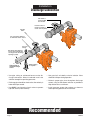
Installation
Suction Connection
When Flooded Suction Exists
Water under
pressure
Pump driven by remote
power source, direct
coupling or pulley/belt
connection.
Maintain minumum
liquid level to prevent
vortexing.
Short run of straight pipe after
reducer (2 times pipe diameter).
Eccentric Reducer
flat side up.
Suction
Gauge
2214 0196
See foundation
section.
Isolation Valve
full open when
pumping.
Straight run, short as possible but
at least 6 times pipe diameter after
pipe fitting to stabilize flow.
Slope upward to pump.
Support pipe
as required
• Use pipe, tubing, or reinforced hose to make suction
connection. Hose must have sufficient strength to
resist collapse under the atmospheric pressure
differential that may occur while pump is running.
• It is important, even with a flooded suction condition,
that proper pipe fittings are used so water is delivered
to impeller eye with a smooth flow and consistent
velocity.
Standard or
long radius
elbow.
• An isolation valve is used in a pressurized suction
pipe to permit servicing pump.
• Piping run and connection fittings should be properly
aligned and independently supported to reduce strain
on pump case.
• If solids are present, a strainer should be used to
protect the pump.
• Suction pipe size should be at least one commercial
pipe size larger than opening of pipe inlet. Flow
velocity should not exceed 8 ft./sec.
Recommended
Page 10
F00633
Installation
Suction Connection
When Flooded Suction Exists
Water under
pressure
Inverted Eccentric Reducer
may result in air pocket.
Valve in upward
position may trap
air.
2215 0196
Do not leave
valve partially
closed.
Check Valve
in suction pipe
not needed.
Unsupported pipe causes
excessive stress on pump
and fittings.
Concentric Reducer may
cause air pockets.
Miter elbow or short
radius elbow not
recommended.
Do not make elbow
connection directly
to pump suction.
• Suction piping that is undersized will create excess
friction losses that may cause cavitation and a
reduction in pump performance.
• Excess fittings and bends in suction line results in
trapped air, reduced performance, and high friction
losses which may cause cavitation.
• If check valve is required for back flow prevention,
locate on the discharge side of pump.
Not Recommended
F00633
Page 11
Installation
Discharge Connection
Non-Slam or
spring loaded
check valve.
Isolation
Valve
Isolation valve to
permit servicing of
check valve or pump.
Use Concentric Reducer
to mimimize friction losses.
Pressure
Gauge
Discharge pipe diameter
at least one nominal pipe
size larger than discharge
opening in pump.
Align piping to
minimize flange
stress.
Support piping
as required
2118 1195
• Use pipe, tubing or reinforced hose to make discharge connection. Material selected must have
sufficient strength for operating pressures.
• Use gate, ball, or butterfly valve for isolation. Valve
should be full open during operation.
• Discharge pipe should be sized so that flow velocity is
below 8 feet per second.
• Maintain proper pipe size throughout discharge
system, using as few elbows and tees as possible to
keep friction loss to a minimum.
• Use ONLY non-slamming check valves to prevent
hydraulic shock (water hammer).
• Install pressure gauge after reducer as shown to
check operating pressure or shut-off head.
Recommended
Page 12
F00633
Installation
Discharge Connection
Do not use Gate Valve
to throttle flow.
Avoid check valves
that may cause
hydraulic shock.
Avoid abrupt change
in pipe size.
Avoid undersized
pipe diameter.
Do not leave
pipe unsupported.
2119 1195
Do not force alignment
that can cause flange
stresses.
• Avoid excess friction loss caused by numerous
fittings, insufficient pipe diameter, and sharp turns in
pipe run.
• Swing type check valves can permit build-up of
reverse velocity before closing causing hydraulic
shock or “water hammer.”
Not Recommended
F00633
Page 13
Start-up
General Information
CHECK ROTATION:
Before pump is put into operation, rotational direction
must be checked to assure proper performance of
pump. Refer to illustration below to varify proper
rotational direction for each model covered in this
manual.
Hazardous voltage. Can shock, burn, or
cause death. Disconnect power to pump before
servicing.
Do not attempt any wiring changes without first
disconnecting power to pump.
PRIMING:
Viewed from
this direction
STARTING (Electric Motor):
NOTICE: Never run pump dry. Running pump without
water will overheat pump and damage internal parts.
Always make sure pump is primed prior to start-up.
NOTICE: Refer to maintenance section if pump has
packing for adjustment prior to start-up.
Prime pump by the above method. Turn on power to
pump. Slowly open discharge valve until desired flow
rate is achieved. Place the “Hand-Off-Auto” selector
switch in the “Auto” position. The pump will start
automatically when the pilot device signals the motor
starter.
STOPPING (Electric Motor):
Pump will stop automatically when the pilot device deenergizes the motor starter. Turn the “Hand-Off-Auto”
selector switch to “Off” position if you want to stop the
pump while it is running.
Counter-Clockwise Rotation
B2ZRKL
Count
erC
n
atio
rot
12
9
12
3
9
3
6
6
As viewed
As viewed
ise
kw
loc
Clockwise Rotation
B2XRKS
B3TRKS
B4ZRKS
Clock
wis
e
Pump priming is the displacement of air with water in
the pump and suction piping. Pump MUST BE
completely filled with water when operating.
A self-priming pump only needs to be manually primed
at the first start-up. Once primed, under normal
conditions pump will reprime automatically at each
subsequent start-up.
To prime, remove plug from top of pump case and fill
case with water. Replace plug and start pump. Unit is
equipped with a flapper type check valve which will
open at start-up and allow pump to evacuate air from
the suction line. After several minutes of operation,
pump will be fully primed and pumping water. Priming
time will vary, depending on length and diameter of
suction line.
Engage start switch momentarily
(bump driver) to observe rotational
direction.
2238 0196
ELECTRIC MOTORS:
Single Phase: Refer to wiring information on the
motor plate to obtain proper rotation.
Three Phase: If pump runs backwards, reverse any
two leads coming of incoming power (L1, L2, L3) until
proper rotation is obtained. Reverse L1 and L2, L2
and L3, or L1 and L3.
Pump running backwards - Centrifugal pumps will still
Page 14
pump liquids, however, GPM and head will be a
fraction of the published performance.
ENGINE DRIVEN:
If engine is used for pump driver, check with engine
instruction and operation manual or engine
manufacturer to determine how rotation is defined,
then use above illustration for proper connection.
F00633
Maintenance
General Information
LUBRICATION:
LIQUID END of pump requires no lubrication. Wear
rings, packing rings, and models using a mechanical
shaft seal, are lubricated by the liquid being pumped. Do
not run dry!
BEARING FRAME - add approximately 2 ounces of a
lithium-based NGLI No. 2 extra pressure ball bearing
grease to each bearing during quarterly inspection.
Bearings will run hotter for a brief run-in period after
packing which is normal. However, worn bearings will
cause excessive temperatures and need to be
replaced. The pump unit is cooled by the water flowing
through it, and will normally be at the temperature of
the water being pumped.
GAS/DIESEL ENGINE: Refer to engine manufacturer’s
operating manual for complete instruction.
STUFFING BOX: After a short period of operation,
verify that the stuffing box area and gland are not hot.
If heating is detected, loosen the gland nuts evenly
until water is just running out of stuffing box in a
DROPLET form (approximately 40-60 drops per
minute). Water must not be streaming or spraying out.
Verify cool operation periodically. Adjust gland nuts
EVENLY as necessary for lubrication and cooling of
the packing. If packing has been tightened to the limit
of the packing gland travel, additional packing is
necessary.
PERFORMANCE CHECK:
PUMPS WITH PACKING: Starting new pump.
Periodically check the output of the pump. If performance is noticeably reduced, refer to Troubleshooting
Chart.
Before starting pump for the first time, loosen gland nuts
and retighten finger tight. Proceed with pump start-up
procedure. Allow packing to leak liberally for a few
moments. Then tighten gland nuts one complete turn
each until leakage is reduced to 40 to 60 drops per
minute.
NOTE: Excess grease will cause bearings to run hot.
The following are factory approved brands of grease for
use with Berkeley Pumps: Alvania EP2, Shell Oil;
Mobilith AW2, Mobil Oil, Ronex MP, Exxon, Litholine
EP2, Atlantic Richfield; and Amolith EP2, Amoco.
ELECTRIC MOTOR: Refer to motor manufacturer’s
operating manual for complete instruction.
OBSERVATIONAL MAINTENANCE:
When the pump and system operation have been
stabilized, verify that pump unit is operating properly.
Observe the following:
VIBRATION: All rotating machines can be expected to
produce some vibration, however, excessive vibration
can reduce the life of the unit. If the vibration seems
excessive, discontinue operation, determine cause of
the excessive vibration, and correct.
NOISE: When the unit is operating under load, listen
closely for unusual sounds that might indicate that the
unit is in distress. Determine the cause and correct.
OPERATING TEMPERATURE: During operation, heat
is dissipated from the pump and the driver. After a
short period of time, the surface of the pump bracket
will be quite warm (as high as 150°F), which is normal.
If the surface temperature of the pump bracket or
driver is excessive, discontinue operation, determine
cause of the excessive temperature rise, and correct.
F00633
REPACKING:
Refer to illustration on Page 16.
PUMPS WITH MECHANICAL SEAL:
Adjustment or maintenance is normally not required.
The seal is enclosed within the pump and is self
adjusting. Seal is cooled and lubricated by the liquid
being pumped. Consult factory for proper replacement
procedure.
SHAFT:
Bearing frame shaft assemblies should be periodically
torn down for inspection of worn parts, cleaning and regreasing. Most importantly, to check shaft sleeve and
bearings for pitting. Replace worn components as
necessary.
Page 15
Maintenance
Packing Ring Replacement
Removal
Packing
Hooks
Packing
Gland
Shaft
Packing
Ring
2239 0196
2 x Scale
1
1
2
2
• Unfasten hardware holding Packing Gland in place
and slide back on shaft to expose packing rings.
• Remove packing rings from Stuffing box using two
commercially available Packing Hooks as shown.
• Slide Lantern Ring (if used) back to expose any
remaining rings, including metallic. Remove them in
the same manner.
Installing New Rings
Stagger ring joints
90 degrees apart
Shaft
2240 0196
Packing
Rings
Metallic Ring
Lantern Ring
• Clean shaft sleeve and Packing Gland.
• Inspect shaft sleeve for wear, replace if needed.
• Install new packing rings in stuffing box by placing
over shaft sleeve and pushing them in as far as they
will go.
• Rotate ring joint 90 degrees when installing each ring
as shown.
Page 16
• Slide packing gland into position, then gently and
evenly tighten nuts to force rings into place and seat
(do not overtighten). Loosen nuts again to hand tight.
• Start primed pump and allow packing to leak liberally.
• Tighten gland nuts one complete turn each until
leakage is reduced to 40 to 60 drops per minute.
F00633
Maintenance
General Pump Care
ROUTINE MAINTENANCE
WINTERIZING
A well maintained pumping system will extend the life of
the unit and will require fewer repairs. This means less
down time which can be very critical when a constant
delivery of water is required.
If pump is to be out of service for an extended period of
time, such as the winter months, the following storage
procedures should be followed.
A routine maintenance and inspection schedule should
be set up on a weekly, quarterly, and annual basis with
records kept of these actions. For weekly checks see
observational maintenance on Page 15. For quarterly
and annual maintenance, refer to check list on Page 22.
Copy page as necessary for continual usage.
RECOMMENDED SPARE PARTS
It is recommended that the following spare parts be kept
on-site as a minimum back-up to service your pump and
reduce down-time. Check your model/style against parts
breakdown drawing on Pages 18 and 19 when selecting
spares.
•
•
•
•
•
•
Mechanical Shaft Seal
Packing Set and Packing Hooks
Shaft Sleeve(s)
All Gaskets and O-Rings Required for One Pump
Oil Seal(s)
Bearings
If having a pump non-operational has severe consequences, a back-up pump should be considered.
Otherwise, a back-up impeller, volute case, bearings
and shaft, would be prudent.
PUMP PROTECTION-COLD WEATHER/
WET WEATHER INSTALLATIONS:
SYSTEM DRAINS: Provide drain valves to empty
system, including pump case, to prevent freezing
damage.
• Remove exterior dirt and grime or any substance that
may trap moisture. Exposed metal is subject to
oxidation, prime and repaint if necessary. If this is not
possible, coat with grease or heavy oil.
• Flush suction and discharge lines. Check for leaks at
this time and replace any worn gaskets.
• Remove lowest plug in pump and drain pump casing
and suction and discharge lines.
• Lubricate bearings.
• If possible, keep unit clean and dry during storage
period to guard against corrosion.
• Seal all open ports to keep out foreign objects such
as insects, rodents, dust and dirt.
• Rotate driver shaft periodically to prevent freeze-up of
internal components.
• Shelter unit from elements if possible.
• Work oil into impeller wear ring by dripping oil into the
gap while rotating by hand.
SPRING START-UP
• Inject sufficient grease into the bearings to displace
old grease.
• Visual inspection.
• Rotate by hand, if any binding occurs, disassemble
and inspect.
SHELTER: If possible, provide shelter for unit to protect
from weather. Allow adequate space around pump unit
for service. When effectively sheltered, a small amount
of heat will keep temperature above freezing. Provide
adequate ventilation for unit when running. For severe
weather problems, where other shelter is not practical, a
totally enclosed fan-cooled enclosure can be considered
for electric motors.
CONDENSATION: When the temperature of metal parts
is below dew point and the surrounding air is moist,
water will condense on the metal surfaces and can
cause corrosion damage. In severe situations, a space
heater can be considered to warm the unit.
F00633
Page 17
Pump Nomenclature
General Information
ORDERING REPLACEMENT PARTS:
Locate the Berkeley nameplate on the pump, plate is
normally on the bearing bracket. Information found on
this plate is shown below. To be sure of receiving correct
parts, provide all nameplate data when ordering. The
BM (Bill of Material) number is most important. Write
your nameplate information on the blank nameplate
below for future reference as nameplates can become
worn or lost.
BERKELEY PUMPS
MODEL
S.N. OR DATE
IMPELLER DIA.
B.M.
SAMPLE ONLY
344 1093
Record your nameplate data here.
BERKELEY PUMPS
MODEL
S.N. OR DATE
B2ZRKL
B3TPMS
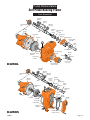
The following illustrations show typical components used
in the assembly of self priming bearing frame mounted
centrifugal pumps. Refer to these drawing when ordering any replacement parts.
G021196
G100894
IMPELLER DIA.
B.M.
B54598
B52346
6-1/8"
9.00”
788 0394
Belt
Drive
Shaft / Bearing
Assembly
Coupling
Drive
Sheave
Bearing
Frame
Case
Gasket
Pump Case
(Volute)
Water
Slinger
Mechanical
Seal
Clack
Weight
Rubber Clack
(Check Valve)
Clack
Washer
2137N 1195
Impeller
B2XRKS/B3TRKS
Page 18
Suction
Cover
F00633
Pump Nomenclature
Self Prime Bearing Frame
Parts Breakdown
Outboard
Bearing
Bearing
Spacer
Outer Bearing
Cap
Inboard
Bearing
Bearing
Frame
Bearing
Lockwasher
Shaft
Case Gasket
Bearing Lock
Nut
Inner
Bearing Cap
Slinger
Packing Gland
Packing Ring
Assembly
Impeller
Shaft
Sleeve
2135N 1195
Lantern Ring
Impeller
Washer
Impeller
Screw
Suction Flange
Gasket
Rubber
Clack
Clamp
Pump Case
(Volute)
Washer
Weight
Clack Assembly
(Check Valve)
Suction Flange
(Check Valve)
B2ZRKL
Outboard
Bearing
Bearing
Spacer
Inboard
Bearing
Outer Bearing
Cap
Bearing
Frame
Shaft
Mechanical
Seal
Bearing
Lockwasher
Bearing
Lock Nut
Inner
Bearing Cap
Oil Seal
Shaft
Sleeve
Slinger
Retaining
Ring
Truarc
2106N 1095
Clack
Weight
Clack
Washer
Impeller
Impeller
Lock Nut
Suction
Cover
Case Gasket
Pump Case
(Volute)
B4ZRKS
F00633
Rubber Clack
(Check Valve)
Page 19
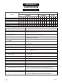
Maintenance
Troubleshooting
Electrical Drive Pumps
PROBABLE CAUSE
SYMPTOM
A
Pump runs, but no water delivered
Not enough water delivered
Not enough pressure
Excessive vibration
Abnormal noise
Pump stops
Overheating
X
B
X
X
C
GROUP I
ELECTRICAL
D
E
F
X
X
X
X
X
X
X
X
G
H
I
X
X
X
X
X
X
A
X
X
X
X
X
E
F
X
X
X
GROUP III
SYSTEM
A
B
C
X
X
X
X
X
X
X
X
X
X
X
X
X
X
X
CAUSE
GROUP II
MECHANICAL
B
C
D
X
X
X
X
X
X
X
X
X
X
CORRECTIVE ACTION
I. ELECTRICAL
A. No voltage in power system
Check phase-to-phase on line side of starter contactor.
Check circuit breaker or fuses.
B. No voltage on one phase
(Three Phase Units)
Check phase voltage on line side of starter contactor. Isolate open circuit
(circuit breaker, fuse, broken connections, etc.)
C. Low voltage at motor
Running voltage across each leg of motor must be ±10% of nominal
voltage shown on nameplate.
D. Motor leads improperly grouped
for voltage
Refer to lead grouping diagram on motor nameplate.
E. Control failure
Check control device, starter contactor, H-O-A selector switch, etc.,
for malfunction.
F. Thermal overload switch open
Check phase-to-phase on line side of starter contactor.
G. Installation failure
Check motor or windings to ground with megohmmeter.
H. Open windings
Check leg-to-leg with ohmmeter.
I. Frequency variation
Check frequency of power system. Must be less than 5% variation from
motor nameplate rating.
II. MECHANICAL
A. Flow through pump completely or
partially obstructed
Locate and remove obstruction. Refer to Repair Instructions
for disassembly.
B. Wrong direction of rotation
Reverse rotation of three phase motor by interchanging any two leads.
See manufacturer’s Instructions for reversing single phase motor.
C. Pump not primed
Reprime. Inspect suction system for air leaks.
D. Internal leakage
Check impeller for wear of controlled clearances (See Repair Instructions).
E. Loose parts
Inspect. Repair.
F. Stuffing box not properly adjusted
Adjust gland.
III. SYSTEM
A. Pressure required by system at design
flow rate exceeds pressure rating of pump
Compare pump pressure and flow rate against pump characteristic curve.
Check for closed or partially closed valve in discharge piping system.
Reduce system pressure requirement. Increase pressure capability of pump.
B. Obstruction in suction piping
Locate and remove obstruction.
C. Pressure rating of pump exceeds pressure
requirement of system at design flow rate
Compare pump pressure and flow rate against pump characteristic curve.
Inspect discharge piping system for breaks, leaks, open by-pass valves, etc.
If necessary, reduce flow rate by partially closing discharge valve.
Page 20
F00633
Maintenance
Troubleshooting
Engine Drive Pumps
SYMPTOM
Pump runs, but no water delivered
Not enough water delivered
Not enough pressure
Excessive vibration
Abnormal noise
Pump stops
Overheating
A
X
X
X
B
GROUP I
ENGINE
C
D
X
X
X
X
X
X
X
X
X
E
X
X
X
X
X
X
CAUSE
F
PROBABLE CAUSE
GROUP II
MECHANICAL
A
B
C
D
E
X
X
X
X
X
X
X
X
X
X
X
X
X
X
X
X
GROUP III
SYSTEM
A
B
C
X
X
X
X
X
X
X
X
X
X
X
X
F
X
X
X
X
CORRECTIVE ACTION
I. ENGINE
A. Speed too low
Refer to engine manufacturer’s manual.
B. Rotating and/or
reciprocating parts drag
Refer to engine manufacturer’s manual.
C. Speed too high
Refer to pump and engine power curves. Adjust.
D. Loose or broken parts
Refer to engine manufacturer’s manual.
E. Improper adjustment
Check fuel and ignition systems. Adjust per engine manufacturer’s manual.
F. Fuel supply
Check fuel supply, fuel pump, filters, etc.
II. MECHANICAL
A. Flow through pump completely or
partially obstructed
Locate and remove obstruction. Refer to Repair Instructions
for disassembly.
B. Wrong direction of rotation
Reverse rotation of three phase motor by interchanging any two leads.
See manufacturer’s Instructions for reversing single phase motor.
C. Pump not primed
Reprime. Inspect suction system for air leaks.
D. Internal leakage
Check impeller for wear of controlled clearances (See Repair Instructions).
E. Loose parts
Inspect. Repair.
F. Stuffing box not properly adjusted
Adjust gland.
III. SYSTEM
A. Pressure required by system at design
flow rate exceeds pressure rating of pump
Compare pump pressure and flow rate against pump characteristic curve.
Check for closed or partially closed valve in discharge piping system.
Reduce system pressure requirement. Increase pressure capability of pump.
B. Obstruction in suction piping
Locate and remove obstruction.
C. Pressure rating of pump exceeds pressure
requirement of system at design flow rate
Compare pump pressure and flow rate against pump characteristic curve.
Inspect discharge piping system for breaks, leaks, open by-pass valves, etc.
If necessary, reduce flow rate by partially closing discharge valve.
F00633
Page 21
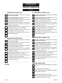
Maintenance
Routine Inspection
Record
I. QUARTERLY INSPECTION
III. QUARTERLY INSPECTION
Inspect all system piping connections for leakage
or possible misalignment.
Check pump foundation for soundness and see
that all hold-down bolts are secure.
Complete any lubrication requirements as dictated
by pump and driver owner’s manual.
Inspect packing or mechanical seal for possible
replacement. Examine shaft sleeve, if present, for
wear and replace if necessary.
Inspect pumping plant panel for signs of wear (ie:
replace pitted contactors, etc., as needed).
Check pump and motor bearings from signs of
wear. Repack or replace as necessary.
Check alignment of couplings and/or pulleys and
belt tension if applicable.
________________________________________
________________________________________
II. QUARTERLY INSPECTION
IV. QUARTERLY INSPECTION
Inspect all system piping connections for leakage
or possible misalignment.
Check pump foundation for soundness and see
that all hold-down bolts are secure.
Complete any lubrication requirements as dictated
by pump and driver owner’s manual.
Inspect packing or mechanical seal for possible
replacement. Examine shaft sleeve, if present, for
wear and replace if necessary.
Inspect pumping plant panel for signs of wear (ie:
replace pitted contactors, etc., as needed).
Check pump and motor bearings from signs of
wear. Repack or replace as necessary.
Check alignment of couplings and/or pulleys and
belt tension if applicable.
________________________________________
________________________________________
ANNUAL INSPECTION
NOTES:
Inspect pump and entire pumping system for signs
of wear.
Inspect system valves, screens, etc.
If electric motor is used, check windings for degredation, rewind if necessary.
Check pump impeller eye for clearance.
Inspect impeller, volute case, and seal chamber for
signs of excessive wear or corrosion.
Page 22
F00633
Maintenance
Notes
F00633
Page 23
Berkeley
Warranty
Berkeley/Wicor Canada, Inc. (“Wicor”) warrants to the original consumer purchaser (“Purchaser”) of its
products that they are free from defects in material or workmanship.
If within twelve (12) months from the date of installation or twenty-four (24) months from the date of
manufacture any such product shall prove to be defective, it shall be repaired or replaced at
Berkeley’s/Wicor’s option, subject to the terms and conditions set forth below.
General Terms and Conditions
Purchaser must pay all labor and shipping charges necessary to replace product covered by this
warranty. This warranty shall not apply to products which, in the sole judgement of Berkeley/Wicor, have
been subject to negligence, abuse, accident, misapplication, tampering, alteration; nor due to improper
installation, operation, maintenance or storage; nor to other than normal application, use or service,
including but not limited to, operational failures caused by corrosion, rust or other foreign materials in the
system, or operation at pressures in excess of recommended maximums.
Requests for service under this warranty shall be made by contacting the installing Berkeley/Wicor dealer
as soon as possible after the discovery of any alleged defect. Berkeley/Wicor will subsequently take
corrective action as promptly as reasonably possible. No requests for service under this warranty will be
accepted if received more than 30 days after the term of the warranty.
The warranty on all three phase submersible motors is void if three-leg overload protection of
recommended size is not used.
This warranty sets forth Berkeley’s/Wicor’s sole obligation and purchaser’s exclusive remedy for defective
products.
BERKELEY/WICOR SHALL NOT BE LIABLE FOR ANY CONSEQUENTIAL, INCIDENTAL, OR
CONTINGENT DAMAGES WHATSOEVER.
THE FOREGOING WARRANTIES ARE EXCLUSIVE AND IN LIEU OF ALL OTHER EXPRESS
WARRANTIES. IMPLIED WARRANTIES, INCLUDING BUT NOT LIMITED TO THE IMPLIED
WARRANTIES OF MERCHANTABILITY AND FITNESS FOR A PARTICULAR PURPOSE, SHALL NOT
EXTEND BEYOND THE DURATION OF THE APPLICABLE EXPRESS WARRANTIES PROVIDED
HEREIN.
Some states do not allow the exclusion or limitation of incidental or consequential damages or limitations
on how long an implied warranty lasts, so the above limitations or exclusions may not apply to you. This
warranty gives you specific legal rights and you may also have other rights which vary from state to state.
In the U.S.: Berkeley, 293 Wright St., Delavan, WI 53115
In Canada: Wicor Canada, 4544 Fieldgate Parkway, Mississauga, Ontario L4W 3W6
Page 24
F00633