1
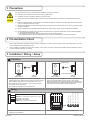
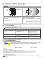
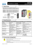
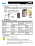
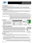
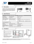
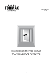
MS-08 MAGIC SWITCH USER’S GUIDE MICROWAVE CONTACTLESS SWITCH FOR AUTOMATIC DOORS 1 Description Screw Microwave Motion Sensor Screw Screws Microwave Motion Sensor Screws Adapter Ring Faceplate Faceplate SINGLE GANG DOUBLE GANG MS-08 MAGIC SWITCH (10MS08U) 2 Specifications DESCRIPTION SPECIFICATION Technology Microwave motion sensor Radiated Frequency 24.125 GHz Radiated Power Density 5 mW/cm² Supply voltage 12 to 24VAC ± 10% 12 to 24VDC +30% / -10% Supply Frequency 50 to 60Hz Power Consumption < 1.5W Output Relay contact rating (max voltage) Relay contact rating (max current) Max switching power Relay with switch-over contact (voltage free) 60 VDC/ 125 VAC 1A (resistive) 30W (DC)/ 60VA (AC) Detection Range 4” to 24” (adjustable) Detection Mode Motion (bidirectional) Output Hold Time 0.5s (in pulsed mode) Temperature Range -4°F to + 131°F Immunity Immune to electrical and radio frequency interference Weight 0.34 lbs. Material ASA, Nylon, PC Certification Electromagnetic compatibility (EMC) according to 2004/108/EC FCC: G9B-MS08 IC: 4680A-MS08 75.5265.01 20071031 Page 1 of 3 3 Precautions Shut off all power going to wall outlet before attempting any wiring procedures. Maintain a clean & safe environment when working in public areas. Constantly be aware of pedestrian traffic around the door area. Always stop pedestrian traffic through the doorway when performing tests that may result in unexpected reactions by the door. ESD electrostatic discharge: Circuit boards are vulnerable to damage by electrostatic discharge. Before handling any board ensure you dissipate your body’s charge. Always check placement of all wiring before powering up to insure that moving door parts will not catch any wires and cause damage to equipment. Ensure compliance with all applicable safety standards (i.e. ANSI A156.10 / A156.19) upon completion of installation. DO NOT attempt any internal repair of the sensor. All repairs and/or component replacements must be performed by BEA, Inc. Unauthorized disassembly or repair: 1. May jeopardize personal safety and may expose one to the risk of electrical shock. 2. May adversely affect the safe and reliable performance of the product will result in a voided product warranty. 4 Pre-Installation Check 1. When wiring multiple devices together creating a system configuration, it is best to ensure that each device works independently. This will reduce troubleshooting if a discrepancy occurs. 2. Prior to installing any equipment in either new or existing circuits, ensure correct line voltage and line stability. Always remember to shut the power OFF before performing circuit wiring. 5 Installation / Wiring / Setup 1 Installation Adapter Ring Gang Box Metal or Plastic Foam Gasket MS-08 Assembly Gang Box Metal or Plastic 1. The MS-08 may be mounted in conventional metal or plastic electrical gang boxes. Make sure the unit sensor does not come in contact with the metal gang box to avoid shorting out the unit. • PWR: Black - 12 to 24 VAC / VDC: -5% to +10% • PWR: Red - 12 to 24 VAC / VDC: -5% to +10% • NC: Empty - NC Contact • NO: Green - NO Contact • COM: White - Common at Door Control C O N T R O L NC NO COM POWER 1. Wire the 4-conductor cable to the door operator according to manufacturer specifications. Page 2 of 3 Black - 12 to 24 VAC / VDC M S 0 8 Red - 12 to 24 VAC / VDC Wiring White - Com at Door Control 2 Green - NO Contact • Do not place the sensor in the door’s opening range, where the sensor may see door movement. Do not place moving objects in front of the sensor. 2. Depending on the door installation, the weather resistant foam gasket or the plastic adapter ring may be used. The weather resistant foam is used as a protective barrier against the elements. The plastic adapter ring is designed to enable the double gang face plate to attach to various plastic and metal gang boxes. Empty - NC Contact • MS-08 Assembly NC NO COM POWER 2. Attach the 4-conductor cable connector to the Magic Switch. 75.5265.01 20071031 5 Installation and Wiring (Continued) 3 Setup Toggle Mode Pot 4” 3 Output Mode Switch 24” 4” Pulse Mode 24” MS-08 1. Adjust unit to desired setup. Two adjustments can be made to the sensor. The Potentiometer is used to adjust the size of the units’ sensing field and the Output Mode switch is used to select Toggle or Pulse mode. 2. Rotate potentiometer clockwise to increase the sensing field. It may be adjusted from 4” to 24”. Sensing Filed 2. Adjust Output Mode by moving switch in the up position (Toggle Mode) or in the down positon (Pulse Mode). Toggle Mode: Recommended for switch applications. In Toggle mode a detection activates the relay and a second detection deactivates the relay. Pulse Mode: Recommended for automatic door applications. In Pulse mode a detection activates the relay for a short period of time - depending on the duration of movement in front of door. 6 Troubleshooting 1 Troubleshooting Procedures PROBLEM PROBABLE CAUSE CORRECTIVE ACTION Door does not open when swiping hand in front of sensor. 1. Bad or no power supply. 2. Detection range is too small 3. Wrong connection. 1. Check power supply. If LED switches on or flashes, power connections are OK. 2. Adjust the detection range. Remove any metal plates in front of sensor. 3. Check wiring and relay connection. Door remains permanently open. 1. Environmental conditions are influencing the sensor. 2. Wrong connection. 1. Remove any moving objects close to the sensor. 2. Check wiring and relay connection. The door remains open after detection/ activation. 1. Wrong output mode. 2. Wrong connection. 1. Switch the output mode to Pulse mode. 2. Check wiring and relay connection. 12 Company Contact Do not leave problems unresolved. If a satisfactory solution cannot be achieved after troubleshooting a problem, please call BEA, Inc. If you must wait for the following workday to call BEA, leave the door inoperable until satisfactory repairs can be made. Never sacrifice the safe operation of the automatic door or gate for an incomplete solution. The following numbers can be called 24 hours a day, 7 days a week. For more information, visit www.beasensors.com. US and Canada: Canada: Northeast: 1-866-249-7937 1-866-836-1863 1-866-836-1863 Southeast: Midwest: West: 1-800-407-4545 1-888-308-8843 1-888-419-2564 FCC APPROVAL This device complies with Part 15 of the FCC Rules and with RSS-210 of Industry Canada. Operation is subject to the following two conditions: *this device may not cause harmful interference, and *this device must accept any interference received, including interference that may cause undesired operation. This equipment has been tested and found to comply with the limits for a Class B digital device, pursuant to part 15 of the FCC Rules. These limits are designed to provide reasonable protection against harmful interference in a residential installation. This equipment generates, uses and can radiate radio frequency energy and, if not installed and used in accordance with the instructions, may cause harmful interference to radio communications. However, there is no guarantee that interference will not occur in a paticular installation. If this equipment does cause harmful interference to radio or television reception, which can be determined by turning the equipment off and on, the user is encouraged to try to correct the interference by one or more of the following measures: *Reorient or relocate the receiving antenna *Increase the separation between the equipment and receiver *Connect the equipment into an outlet on a circuit different from that to which the receiver is connected *Consult the dealer or an experienced radion/TV technician for help WARN NG: CHANGES OR MOD FICATIONS TO THIS EQU PMENT NOT EXPRESSLY APPROVED BY BEA INC. MAY VO D THE FCC AUTHORIZATION TO OPERATE THIS EQU PMENT. 75.5265.01 20071031 Page 3 of 3