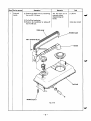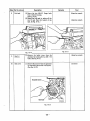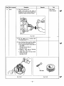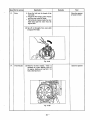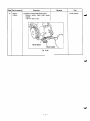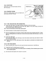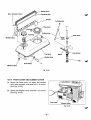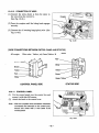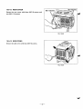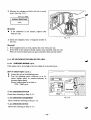
1
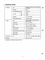
OPERATOR'S MANUAL FOR YOUR
MODEL PC13R
SERIAL NUMBER
_______________
BALDOR GENERATORS
3815 OREGON STREET ◊ P.O. BOX 200 ◊ OSHKOSH WI 54902-0200
TELEPHONE: (920) 236-4200 ◊ FAX: (920) 236-4219
FORM#: S-PSG-002-25
EFFECTIVE/REVISED: 6/29/01
D:\ISO9001\FORMS\S-PSG-002-37\msw
FORWARD
This manual contains the information you need to safely and efficiently operate your generator
set. During the preparation of this manual every effort was made to ensure the accuracy of its
contents.
DO NOT OPERATE THIS GENERATOR SET UNTIL YOU CAREFULLY READ THIS
MANUAL AND UNDERSTAND THE SAFETY WARNINGS AND INSTRUCTIONS
CONTAINED IN IT. While safety is built into every Baldor Pow'R Gard generator set, careless or
improper operation could possibly result in mechanical failure, property damage, severe injury
or even death.
Note that this manual covers only very basic information in regards to the engine. A separate
owner's manual for the engine is supplied with this unit for your use. Please refer to this manual
for information relative to engine operation, maintenance, recommendations and additional
safety warnings.
As soon as you receive your generator set, inspect it closely for shipping damage. If you find
some damage, notify the transportation company immediately and file a freight damage claim.
Think of this manual as a tool to help you get the most out of your generator set. WE
STRONGLY SUGGEST THAT YOU KEEP THIS MANUAL WITH YOUR GENERATOR SET
AND MAKE IT AVAILABLE TO ANYONE USING THE GENERATOR SET. You should refer
to the manual when questions arise in regards to the operation of the generator set and
carefully observe all safety warnings and instructions contained in it.
Baldor Generators, formerly Pow'R Gard Generator Corporation has been in business since
1965. The generator sets we manufacture have earned the reputation of being of high quality
and a dependable product. We take pride in this fact and continue to keep our quality standards
high on our list of priorities. We are also constantly researching new technological ideas to
determine if they could be used to make our generator sets even better.
Thank you for purchasing your Baldor Pow'R Gard Generator Set.
-i-
SAFETY WARNINGS
♦
Place protective covers and guards over the rotating parts, if rotating parts such as the drive shaft, pulley,
belt, etc. are left exposed, they are potentially hazardous.
♦
When cleaning, repairing or inspecting, make sure all moving parts have stopped.
♦
Prior to working on the generator set, disconnect the spark plug and battery to prevent accidental starting.
♦
Use only original equipment or authorized replacement parts. Use of correct parts will assure the operator of
the safety integrity that was designed into the unit.
♦
Unauthorized modifications to the generator set may impair the function and/or safety of the unit.
♦
Do not operate the generator set without a muffler. Inspect periodically and replace if necessary.
♦
Do not touch the hot exhaust components or the high voltage spark plug and coil terminals. While Spark Plug
Voltages are not normally lethal, an involuntary jerk of the hand caused by a hot surface or by an electrical
shock can result in injury.
♦
Repair of electrical generating equipment requires specialized skills. Repair personnel must have a
thorough understanding of generator and small engine repair procedures.
♦
Never inhale exhaust gases. They contain carbon monoxide; a colorless, odorless and extremely
dangerous gas that can cause unconsciousness or death. Symptoms of carbon monoxide poisoning
can include: dizziness, nausea, headaches, sleepiness, vomiting or incoherency. If you or anyone else
experiences any of these symptoms, get out into the fresh air immediately. Shut the unit down and
do not operate it until it has been inspected and, if necessary, repaired.
♦
Never Operate the generator set indoors or in a poorly ventilated area such as a tunnel or cave.
♦
CALIFORNIA PROPOSITION 65 WARNING: engine exhaust from this product contains chemicals known to
the state of California to cause cancer, birth defects or other reproductive harm.
♦
Know how to stop the engine quickly and understand the operation of all controls.
- ii -
SAFETY WARNINGS
♦
Never permit anyone to operate the generator set without proper instructions.
♦
Never allow children to operate the generator set.
♦
Children and pets must be kept away from the area of operation due to the possibility of burns from hot
engine components or injury from any equipment the generator set is powering.
♦
Always wear eye protection and Hearing protection when working near the generator set.
♦
Operate the generator set only with the guards, shields and other safety items in place and working
properly.
♦
Do not put hands, feet, tools or other objects near rotating parts.
♦
Use reasonable care when moving or lifting the unit. The generator set may move around inside the wrap
frame creating "Pinch Points".
♦
Do not run the generator set while it is being moved.
♦
Do not support the generator set from the top of the wrap frame.
♦
Do not operate the generator set while under the influence of alcohol, drugs or medication.
♦
When transporting or using a generator set with the wheel option, secure the unit to prevent it from moving
around.
♦
Do not tamper with or change the engine speed as it has been preset at the factory for proper operation.
♦
Keep hands and face away from the carburetor when the air cleaner is being moved. A sudden backfire can
cause serious burns.
♦
Be careful of hot parts. The muffler and other generator parts become very hot while the engine is running.
♦
Do not "jump start" the generator set.
♦
Sulfuric acid can cause severe injury and can give off gases, which are corrosive and potentially explosive.
Avoid contact with skin, eyes, and clothing. In case of contact, flush area immediately with water.
♦
When transporting a generator set, secure it to prevent it from moving or shifting.
♦
Know how to stop the engine quickly and understand the operation of all controls.
♦
Do not operate electrical equipment while standing in water, on wet ground or with wet hands or shoes.
♦
Use extreme caution when working on electrical components. Potentially dangerous voltage is present
when the engine is running.
- iii -
SAFETY WARNINGS
♦
Always treat the electrical circuits as if they were energized.
♦
Disconnect all leads plugged into the unit Prior to working on it.
♦
Have the electrical circuits serviced only by qualified technicians.
♦
Inspect wiring frequently and replace frayed, broken or poor leads.
♦
Do not connect this unit to any building's electrical system unless you utilize an approved transfer switch or
the main service entrance switch has been disconnected and locked open.
♦
Circuit overload protection must be provided in accordance with national electrical codes and local
regulations.
♦
Check GFCI Receptacles monthly by using the "Test" and "Reset" buttons designed into them.
♦
Depending on your application it may be mandatory to ground or not ground this unit to earth ground.
Comply with local electrical codes.
○○○○
FOR GASOLINE OR DIESEL POWERED GENERATOR SETS
○○○○
♦
Operate the generator set on a level surface. If the generator set is tilted, fuel spillage may result.
♦
Handle fuel with care. It is highly flammable. Use only clean, properly marked and approved safety
containers for refueling and storing fuel.
♦
Stop the engine and allow it to cool before refueling.
♦
Do not overfill the fuel tank. Only fill the tank to within 1/2" of the top of the tank to allow space for fuel
expansion.
♦
If fuel is spilled, wipe it up carefully and wait until the fuel has dried before starting the engine.
♦
Make sure the fuel cap is properly closed after refueling.
♦
Never operate the generator set while smoking.
♦
Never operate the generator set near an open flame.
♦
Never store the generator set with fuel in the tank indoors or in an enclosed, poorly ventilated enclosure
where fuel fumes may reach an open flame, electrical spark or pilot light as on a furnace, water heater,
clothes dryer, etc.
♦
When transporting over long distances or rough roads, drain the fuel tank to prevent leakage and spillage.
- iv -
SAFETY WARNINGS
○○○○
FOR GASOLINE OR DIESEL POWERED GENERATOR SETS
○○○○
♦
Check all fuel supply piping and their connections on a monthly basis for fuel leaks.
♦
Use only approved piping and componentry in your fuel supply system.
♦
A professional, experienced technician should only install the fuel supply system.
♦
Do not run the fuel line up against any sharp objects.
♦
Comply with NFPA regulations and your local codes in regard to shut-off valves, regulators, etc. and any
other recommendations or requirements they may have.
♦
Keep the generator set at least three feet away from buildings or other structures.
♦
Keep the generator set away from flammable and other hazardous materials (trash, rags, lubricants,
explosives, paints, etc.)
♦
Keep the generator set free of grass, leaves and excessive grease and oils.
♦
Allow the generator set to cool before transporting it or storing it indoors.
♦
Have fire extinguisher accessible and nearby while operating the generator set.
♦
This generator set must not be used on or near any forest covered brush covered or grass covered land
unless the engine's exhaust system is equipped with a spark arrester and it must be maintained
in effective working order by the operator.
♦
Operation inside an enclosed compartment or building is a potential fire hazard and should not be done
unless approval is obtained from Baldor Generators. Engine/Generator overheating can cause severe
damage due to restricted, obstructed or improper airflow that is necessary for the proper cooling of the unit.
♦
Hot exhaust gases being discharged by the engine must never be directed toward anything that could catch
fire or explode.
-v-
Section
1
.
2.
Title
Page
.
4.
3
5
.
.
.
6
7
.
8
.
.
9
.
10
11
.
.
12
Warranty Information...............................................................................................
51
1 SPECIFICATIONS
Generator
T-
TY Pe
Brushless, self-exciting, 2-pole, singlephase,
revolving field
Frequency
60 Hz
AC Voltage (Rated current)
120V (8.3 A)
Max.
1300 W
AC Output
:
Rated
DC Output
I
’j
12V- 8.3A (100W)
I
Condenser
system
I
ForcedAir-cooled,4-Stroke,SideValve,
Gasoline
Engine
:
I
Type
I
Displacement
I
8.73 cu. in (143 cm’)
Ii
2.48 x 1.81 in (63 xmm)
46
i
Bore x Stroke
Fuel
1ooow
I
Voltage regulation system
Engine
I
(unleaded)
Gasoline
1 Automotive
Fuel tank
capacity
I
0.9 U.S. gal (3.5 liters
I
1.3 U.S. pints (600cc)
I
Approx. 3.6 hours
i
I
Oilcapacity
pan
8
Continuous operating hours pertank
1
starter
1 Recoil
Ignition system
ignition
state
Solid
I
system
Starting
I
I
Dimensions (L X W
X
I
H)
19.3 x 11.3 x 16.1in (490 x 288 X 41Omm)
I
II
Dry weight
Specifications are subject
to change without notice.
-1-
60.6 Ibs. (27.5 kg)
2. PERFORMANCE CURVES
2-1 AC OUTPUT
7300
1200
1000
800
A
I
600
s
e
3
E
3
0
400
200
1
2
3
4
5
6
7
9
10 11
CURRENT(A)
2-2 DC OUTPUT
Thevoltage curve shownin the left indicates the
characteristic of DC output when charging a battery.
The voltagemay be decreased by 20% when the
resistance load is applied.
”
0
2
4
6
CURRENT (A)
8
10
-2-
3. FEATURES
4
LOW-NOISE
Mounting of Air-cooled, 4-Cycle, Super Side Valve ROBIN Engine (EYlSD-SSVR) and introduction
of a larger muffler into the machine realized low-noise operation.
0
LIGHT-WEIGHT COMPACT
The machine is easy to carried about due
to itslight-weight (27.5kg) and compact design.
0
HIGH OUTPUT (increased maximumoutput)
The 1300W outputis an increase of lOOW over the 6OHz maximum output of the current R1210.
0
EASY OPERATION
The one-touch engine control switch integrates the engine
on/off switch and the choke. All controlsare
conveniently located on the frontpanel.
0
LONG OPERATION
The large 0.9 U.S. gal. (3.5 liter) fuel tank allows about
rated load.
0
3.6 hours of continuous operation at 60Hz
-d
MINIMAL MAINTENANCE
The brushless design and condenser voltage regulator
system ensure maintenancefree operation.
0
FUNCTIONAL FEATURES
The AC/DC push button circuit breaker allows for easy and safe operation when an overload occurs
or when the machineis not functioning properly.
Equipped with voltmeter for reading AC output voltage.
DC output can be obtained for the re-chargeable battery.
0
NOISE PREVENTION
Resistor spark plug prevent electric-wave noise for
radio, T.V., etc.
0
OIL SENSOR (optional)
Theoilsensordetects
when oildecreasesbelow
preventing engine damage.
the designatedlevel,stoppingtheengine
-3-
and
4. GENERAL DESCRIPTION
4-1 EXTERNAL VIEW of GENERATOR
control Engine
DC terminal
Frequency adjusting
,screw
(internal)
switch
(CHOKE-RUN-STOP)
1
starter
cockFuel
'
I
Fuel strainer
\
I
warning
Oil lamp
(With oil sensor type)
\
\
Muffler
Air cleaner
cover
Carrying handle
. Fuel tank cap
Drain
plug
Oil
filler cap
Fig. 4-1
-4-
4-2 LOCATION of SERIAL NUMBER and SPECIFICATION NUMBER
Serial number and specification number are stampedon the LABEL (MODELNAME) stuck on the fuel
-1
tank.
NOTE: Always speciiy these numbers when inquiring about the generator or ordering spare parts
order toget correct parts and accurate service.
Label (Model name)
\
Fig. 4-2
-5-
in
5. CONSTRUCTION AND FUNCTION
5-1 CONSTRUCTION
6P coupler
\
r
l
l
Rotor complete
Rear cover
'I
Condenser
Diode rectifier
rubber Mount
'
\\
Stator complete
I
I
\
Stator cover
Ball bearing
Through bolt
Fig. 5-1
5-2 FUNCTION
5-2-1 STAT0 R
The stator consists of a laminated silicon steel sheet
core,amaincoil
and acondensercoil
which are
wound in the core slots.
The condenser coil excites the rotor field coil which
generates AC voltage in the main coil.
Fig. 5-2
- 6 -
Front cover
5-2-2 CONDENSER
A condenser is mountedontherear
cover andis
connected to the condenser coil which is wound on
the stator. This condenser and condenser coil
regulate the output voltage.
Fig. 5-3
5-2-3
ROTOR
The rotor consists of a laminated silicon steel sheet
core and field coil which wound
is
over the core.
DC current in thefieldcoilmagnetizesthesteel
sheet core. Two permanent magnets are provided for
the primary exciting action.
A coolingfan is pressure-fitted on the endofthe
rotor shaft to cool thecoils, cores, rectifier, and other
generator parts. (See Fig. 5-4)
Fig. 5-4
A diode rectifier and resister are mounted inside
the .insulator. (See Fig.5-5)
of
Cooling air is sucked by the rotor fan through the
slits of therearcoverand
is expelled through the
outlets of the front cover.
Fig. 5-5
-7-
5-2-4 CONTROL PANEL
The control panel has a double AC receptacle with a
ground terminals, and DC terminals.
The voltmeter displays output voltage of the generator. The circuit breaker for AC and DC protects the
generator from getting damages caused by overloading or defective appliance.
Fig. 5-6
- 8 -
5-3 GENERATOROPERATION
PERMANENT MAGNET
FOR INITIAL EXCITATION
SURGE
ABSORBER
I
I
I
‘CONDENSER
Fig. 5-7
5-3-1 GENERATION Of NO-LOADVOLTAGE
When the generator starts running, the permanent magnet built-in to the rotor generates 3 to 6V of
AC voltage in the main coil and condenser coilwound on the stator.
As one or two condensers are connected to the condenser coil, the small voltage at the condenser
coil generates a minute current@ which flows through the condenser coil. At this time, a small flux
is produced with which the magnetic force at the rotor’s magnetic pole is intensified. When this
magnetic force is intensified, the respective voltages in themain coil and condenser coil rise up.
As the current@ increases, the magnetic flux at
the rotor’s magnetic pole increases further.
Thus the
voltages at the main coil and condenser coil keep risingby repeating this process.
As AC current flows through the condenser coil, the density of magnetic flux in the rotor changes.
This change of magnetic flux inducesAC voltage in the field coil,and the diode rectifier in the field
coil circuit rectifies this‘ACvoltage into DC.Thus a DC current @ flows through the field coil and
magnetizes the rotor core to generatean output voltagein the main coil.
When generator speed reaches 3000 to 3300 r.p.m. , the current in the condenser coil and field coil
increases rapidly.
This acts to stabilize the output voltage
of each coils. If generator speed further increasesto the rated
value, the generator output voltage will reach
to the rated value.
5-3-2 VOLTAGE FLUCTUATIONS UNDER LOAD
When the output current@ flows through the maincoil to the appliance,a magnetic fluxis produced and
serves to increase current @ in the condenser coil. When current @ increases, the density of magnetic
w
fluxacrosstherotor
core rises. As aresult,thecurrentflowinginthefieldcoilincreasesandthe
generator output voltageis prevented from decreasing.
-9-
-
5-3-3 DC OUTPUT
DC output is taken out from the DC coil and is fed to
the diode stack (rectifier) where the output undergoes
full-waverectificationand
is then suppliedtothe
load. The diode works to allow the current toflow in
to
the direction @, but does not allow the current
flow in the direction 8, as shown in Fig. 5-8-1.
4
-a
-0
Fig. 5-8-1
Fig. 5-8-2 shows the DC output circuit of the generator. DC voltage is generated in the DC coil. When
the voltage in A is higher than that in Cythe current
@ flows in the direction shown in the figure, while
nocurrentflows
between B and C becausethe
current is cut off by the diodes D,.
On the contrary, when the voltage in C is higher than
that in A, the current @ flows in thedirection as
shown in the figure.No current flows betweenA and
B because the current is cut
off by the diodes D,.
+
Dl
Main
coil
Fig. 5-8-2
As a result, the voltage generated at the output terminal
has a wave form with two peaks in one cycle, as
in the case of the output wave form shown
in Fig. 5-8-3.
Between A and 6
\
1
/
'"0
-.
Between
0
/
I
\
c and B
/ -
/
\
\
Output waveform
I
'\
\
j
0
Curre'nt
flowing
between
A and B
flowing
between
C and B
Fig. 5-8-3
-
CAUTION : Do not use DCand AC output simultaneously.
Due to a characteristic of the condenser
voltage
regulation,
simultaneous
use of
DC
and AC output creates voltage drop In DC output resultingin incapability for charging
batterles.
- 10 -
5-4 ELECTRONIC IGNITION SYSTEM
The electronic ignition system features a power transistor as the current control element. Therefore, the
ignition system is an electronic contact point-free type that operates with the power transistor impulses 4
controlling the current. This system is also called TIC (transistor igniter circuit) and is virtually free of
ignition failure which generally results from contamination of the contact points, a typical problem with
contact type ignition systems.
Because this ignition system has no contact points, it is not affected by moisture, oil, dust, or other
contaminants. As a result, this electronic ignition system ensures sure and positive ignition with reduced
maintenance.
The TIC mechanism consists of a transistor-incorporated ignition coil and a permanent magneto built-in
flywheel which is press-fitted on the rotor shaft of the generator.
Fig. 5-9
(1) When the permanent magneto built-in flywheel start rotating, power is generated in the primary coil
of the ignition coil and current flows to theresistor @ .
From the resistor, current flows the power transistor. With this current, the power transistor turns on,
releasing current
This stagecorresponds to theclosing of contact points.
(2) As the flywheel comes to the point of ignition, timing detecting circuit is activated while the current
@ is flowing through the circuit.
When the ignition timing detecting circuit is activated, the signal transmitter transistor actuates with
current @ flowing. When current@ starts flowing,current @ flowing through the power transistor is
cut quickly. As a result, high voltage is produced in the secondary coil and this voltage is applied
simultaneously to the spark plug which ignites forignition. This stage corresponds to the opening of
contact points.
a.
-
11 -
5-5 OIL SENSOR (OPTION)
-
5-5-1 DESCRIPTION
0
0
The oil sensor mainly functions to detect position
of thesurface of engineoilinthecrankcase
of
engines for generaluse and tostoptheengine
automatically when the oil level goes down below
the lower limit specified.
This prevents seizureof engine from occurring due
to insufficient amount of oil in the crankcase.
Since the sensor has been designed to consume a
part of power supplied to the igniter to energize its
electronic circuit, any other external power supply
is not necessary so that it can be mounted at the
oil filler port.
Introduction of newly developed sensing principle
features super durability and no change with the
passage of time as it does not use any moving part.
I
I
I
i
I
I
i
!
i
1i
\
oil sensor
Fig. 5-10
Merits due to introductionof electrical conductivity detectionare asfollows;
has resistance to mechanical shocks
and property of no change with the passage of time as
sensing element consists simplyof electrodes having no moving parts.
@ At the same time, it is capable of detecting the oil level stably as it is not influenced by engine
vibrations.
@ No error occurs due tofoam and flow of the oil.
@ Influence against the ignition system or the electronic units can be neglected because an electric
current supplied to the sensor can
be decreased.
0 It
-
5-5-2 PRINCIPLE OF SENSING OIL LEVEL
There is a great difference
between electric resistanceof air and that of oil.
Since the resistance of air is far higher than that of oil, more electric current passes through the oil than
through the air, although absolute valueof the current is very smalI.
The sensor detects this current difference
and make use of it.
The sensor judges the oil quantity,by comparing a current flowing across a pairof electrodes (inner and
outer) with the reference, in such a way that if a current flows between the electrodes more than the
reference, sufficient oil is in the crankcase, on the other hand, if a current flows less than the reference,
oil is not sufficient.
Sinceanelectriccurrentisflowntodetectoilquantity,this
is calledthe“electricalconductivity
detection” type of sensor.
The oil level to be detected is determined by the length of electrodes and their mounting positions with
the engine.
5-5-3 HOW IT OPERATES
’
”
[Power supply]
The sensor makes use of a part of primary power source for ignition of the engine (igniter) to drive the
sensor circuit. Powerto the sensor can usually be derived from the ”stop button”by branching wires out.
- 12 -
[Judgement of oil level]
When sufficient oil is in the crankcase, bothof inner and outer electrodes are immersed in the oil through
whichcurrentflowsacrosstheelectrodes.Thesensorjudgesthatoil
in the crankcase is sufficient.
4
When oil level goes down and the inner electrode is exposed to the air due to consumption of oil, no
current flow between the electrodes as isairconsidered to be electrically non-conductive.
The sensor in this case judges that oilis insufficient.
[Decision of oil shortage]
Oil level at the electrodes
may go down momentarily probably due to the engine being slanted
or affected
by vibration even if a sufficient oil isin the crankcase.
For that reason, the sensor has an electronic timer circuit to prevent it from interpreting as short of oil
when amount of oil is sufficient. The sensor has been designed so that the engine is to be stopped only
when oil-shortage is detected for 5 seconds uninterrupted.
The timer employs an integration circuitand it is to be reset when the inner electrode is soaked in the oil
again before the sensor decidesit as oil-shortage.
The oil level where the sensor decides as oil-shortage, when oil level goes down gradually, is called
“threshold level”.
[Automatic stopof engine]
When the sensor decides as oil-shortage, it makes the engine tostop running automatically for protection
of engine.
Once the stopping circuit is activated, it keeps functioning until it confirms that the engine has made a
complete stop, thenthe circuit stops functioning automatically.
e
5-5-4 BLOCK DIAGRAM OF THE CIRCUIT
Power circuit
Igniter
LED indicator
I
Inner pole
oil
-
Detection
circuit
-
Deley circuit
Outer pole
Stopping
circuit
Engine
Fig. 5-1 1
0 Power circuit----*-*---This rectifies a part
of power to the igniter and regulates it to supply the
stabilized power to necessary circuits.
- 13-
-1
@ Detection circuit*****-*
This detects quantity of oil, sufficient or not, according to difference of
electric resistanceacross inner and outer electrodes.
Delay circuit
**.*.-**.-*
This prevents the sensor from making an unnecessary stop of the engine by
momentary lowering of the oil level due to theenginebeing slanted or
affected by vibration in spite of sufficient oilin the crankcase.
@ stopping circuit - - * * * - This automatically stops the enginerunning.
Also, the LED indicator for warning can be’ lit while the engine is being
stopped. We have the wires to be connected to LED available.
5-5-5 CAUTIONS TO BE TAKEN ON HANDLING THE SENSOR
(1) Oil sensor unit
0 Be sure not to damage each wire.
Broken or short-circuited power supply wires and/or a grounding wire in particular may lead to
malfunction or breakdown.
(2) Mounting and wiring of oil sensor unit
0 Although this has been designed to have enough anti-noise properties in practical use, do not route
the sensor wirings in the vicinity of noise-generating sources such as ignition plugs or high voltage
cords. This may cause malfunction or breakdown.
”
@ Since capacity of power source is limited, current flown in the electronic circuit of the sensor is
kept as low as possible.
Be sure to use terminals with a high contact reliability of more than that of tinned terminals.
(3) Operation of oil sensor
0 If operating with the engine kept tilted, oil surface inside of the engine varies and the correct oil
level can not to be detected which in turn obstructs the preventing function of engine seizure.
Operate the engine by keeping it level.
@ When starting the engine with an insufficient oil in the crankcase, engine starts once then it stops
automatically after it runs for about 5 seconds.
@ When the engine has been stopped by the oil sensor, voltage remained in the electronic circuit
prevents the sensor frombeing re-started for 3 seconds after the engine stop.
Try to re-start the engineafter 3 seconds or more.
-
14-
6.
Use extremecaution near fuel. Aconstant danger of explosion or fire exists.
4
Do not fill the fuel tank while the engine is running. Do not smoke or use open flame near the fuel
tank. Be careful not to spill fuelwhen refueling. If spilt, wipe it and letdry before starting the engine.
Do not place inflammable materials
near the generator.
Be careful not to put fuel, matches, gunpowder, oily cloth, straw, and any other inflammables near the
generator.
Do not operate the generator in a room,cave or tunnel.
Always operatein a well-ventilatedarea.
Otherwise the engine mayoverheat and also, the poisonous carbon monoxide contained in the exhaust
gases will endanger human lives. Keep the generator at least 1 m (4 feet) away from structures or
facilities during use.
Operate the generator on a level surface.
If the generator is tilted or moved during use, there is a danger of fuel spillage and a chance that the
generator may tip over.
Do not operate with wet handsor in the rain.
Severe electric shock mayoccur. If the generator is wet by rain or snow, wipe it and thoroughly dry it 4
before starting.
Don’t pour water over the generator directly nor wash it with water.
If the generator is wet with water, the insulations will be adversely affected and may cause current
leakage and electric shock.
Do not connect the generator to the commercial power lines.
This may cause a short-circuit or damage to the generator.
Never connect the generator to the existing house wiring. If connected, the generator will burn out
when the commercial power sourceis recovered.
Don’t operatethe generator with its cover removed.
The operator may be injured or suffer electric shock.
CAUTION; If the circuit breaker tripped off as a result of using an electrical appliance, thecause
can be an
overload or a short-circuit.
In such a case, stop operationimmediately and carefully check the electrical
appliance andplugs for faulty wiring.
- 15-
7.
7-1 AC OUTPUT
Generally, the power ratingof an electrical appliance indicates the amount
of work that canbe done by it.
The electricpowerrequiredforoperating
an electricalappliance is not alwaysequaltotheoutput
wattage of the appliance. The electrical appliances generally have a label showing their rated voltage,
frequency, and power consumption (input wattage). The power consumption of an electrical appliance is
the power necessary for using it. When using a generator for operatingan electrical appliance,the power
factor and starting wattage must be taken into consideration.
In order to determine the right size generator, it is necessary to add the total wattage of all appliances to
be connected to the unit.
Refer to the followings to calculate thepower consumption of each applianceor equipment by its type.
Incandescent lamp, heater, etc. with
a power factor of 1.O
Total power consumption must be equal toor less than the rated output
of the generator.
Example: A rated 1OOOW generator can turn ten lOOW incandescent lamps on.
Fluorescent lamps, Motor driven tools,
light electrical appliances, etc. witha smaller power
factor
Select a generator with a rated output equivalent to 1.2 to 2 times of the power consumption of the
to 3
load. Generally the starting wattageof motor driven tools and light electrical appliances are 1.2
times lager than theirrunning wattage.
Example: A rated 250W electric drill requires a400W generator to start it.
NOTE 7: If a power factor correction capacitor is not applied to the fluorescent lamp, the more
power shall be required todrive the lamp.
NOTE 2: Nominal wattage of the fluorescent lamp generally indicates the output wattage of the
lamp.
Therefore, if the fluorescentlamp has no special indication as to the power consumption,
efficiency should be taken into account as explained
in item (5) on the following page.
Mercury lampswith a smaller power factor
Loads for mercury lamps require 2 3totimes the indicated wattage during start-up.
Example: A 400W mercury lamp requires 800W to 1200W power source to beturned on.
A rated 1OOOW generator can power one 400W mercury lamp
Initially loaded motor driven appliances such as water pumps,compressors,etc.
These appliances require large starting wattage which
is 3 to 5 times of running wattage.
Example: A rated 9OOW compressor requires a 4500W generator to drive it.
NOTE 1: Motor-driven appliances require the aforementioned generator output only
at the starting.
Once their motors are started, the appliances consume about 1.2 to 2 times their rated
power consumption so that the excess power generated by the generator can be used
for other electrical appliances.
(3) and (4) varyintheirrequiredmotor
NOTE 2: Motor-drivenappliancesmentionedinitems
starting power depending on the kind of motor and start-up load.
If it is difficult to
determine the optimum generator capacity,
select a generator with a larger capacity.
- 16-
Appliances without any indication as
to power consumption
Some appliances have no indication as to power consumption; but instead the work load (output) is
indicated. In such a case, power consumption is to beworked out according to thenumerical
formula mentioned below.
(Output of electrical appliance)
(Efficiency)
*
-- (Power consumption)
Efficiencies of some electrical appliances are asfollows:
Single-phase motor
* 0.6 0.75
The smaller the motor, the
Three-phase motor *
* *
*
0.65 0.9 >lower
the efficiency.
Fluorescent lamp
- - - 0.7 0.8
----- ---- --- --------- --- --
Example 1:
-
A 40W fluorescent lampmeansthat
its luminous output is 40W. Its
efficiency is 0.7 and accordingly, power consumption will be 40 + 0.7= 57W. As
explained in Item(2), multiply this power consumption value of 57W by 1.2 2 and
you will get the figure of the necessary capacity of a generator. In other words, a
generatorwith a rated output of 1OOOWcapacity can light nine to fourteen 40W
fluorescent lamps.
Generally speaking, a 400W motor means that its work load is 400W. Efficiency of
this motor is 0.7 and power consumption will be 400 + 0.7= 570W. When this motor
is used for a motor-driven tool, the capacity of the generator should be multiplied by
1.2 to 3 and 570W as explained in the item(3).
-
Example 2:
Applicable wattage
Appliance
60Hz
lncandesent lamp, hot plate
I
I
up to lOOOW
I
Fluorescent lamp, mercury lamp, Electric tool
I
up toabout 800W
to about 250W
Pump, compressor up
I
I
I
I
I
Table 7-1
NOTES: Wiring between generatorand electrical appliances
1. Allowable current of cable
Use a cable with an allowable current that is larger than the rated input current of the load
(electricalappliance). If the input currentis larger thanthe allowable currentof the cable used,
the cable will become excessively heated and deteriorate the insulation, possibly burning it
out.
Table 7-2 shows cablesand their allowable currents for your reference.
2. Cable length
I f along cable is used, a voltage drop occurs due totheincreasedresistanceinthe
conductors decreasingthe input voltage to the load(electrical appliance). As a result, the load
can be damaged.
w
Table 7-2 shows voltage drops per 100 meters of cable.
- 17-
Sectional
mm'
Allowable
A
Gauge No./
wlre element
No./mm
0.75
7
3010.18
1.25
12
5010.18
2.0
17
23
5.5
current
I
area
Voltage
37 10.26
3.5
35
45 10.32
7010.32
Table 7-2
Voltage drop indicates as V
= 100 X R X I X l
R means resistance ( 52 /lo0 m) on the above table.
I means electric current throughthe wire (A).
4! means the length of the wire (m).
The length of wire indicates round length, it means twice the lengthfrom generator to electrical tools.
7-2 DC OUTPUT
NOTE :Do not use DC and AC output simultaneously.
Due to a characteristic of the condenser voltage regulation, simultaneous use of DC and
AC output creates voltage drop
in DG output resulting in incapabilityfor charging batteries.
When the generator is employed to charge batteries, attentions should be paid to the specific gravity of
electrolyte in the battery.
7-2-1 SPECIFIC GRAVITY O F BATTERY ELECTROLYTE
The specific gravityof electrolyte variesby temperature ;so it must be converted to the one at20°C.
S20 = St + 0.0007 (t-20)
where
S20 : The specificgravity at 20°C
St : Measuredvalue
t
: Temperature at the time of measurement (Electrolyte)
-
18 -
7-2-2 SPECIFIC GRAVITY OF BATTERY ELECTROLYTE AND CHARGING CONDITION
Remarks Charglng condintion
Specific gravity (20.c)
1.260
100
1.240
87
1.220
75
1.200
62
1.180
50
1.160
37
Charging is not necessary.
Charging is necessary.
Immediate Chargingis necessary.
I
1.140
1
I
25
7-2-3 BATTERY CAPACITY
The battery capacity is expressed in the unit of AH (ampere-hour). One AH stands for the capacity
one hour.
capable of one ampere current for
- 19-
w
8. MEASURINGPROCEDURES
8-1 MEASURING INSTRUMENTS
8-1-1 “Dr.ROBIN” GENERATOR TESTER
The“Dr.Robin”generatortester
signed for fast, easy diagnosis
generators.
is exclusively deand repair of Robin
The “Dr. Robin” has the following features:
(1) Functions of voltmeter, frequency meter, megger tester, capacitance meter
and circuit tester
are combined in one unit.
(2) Fast and easy readout by digital indicator.
(3) Built-in automatic battery checker indicates the I
Fig. 8-7
time to change batteries.
(4) Tester and accessories are installed in a handy, sturdy case for easy carrying.
0
SPECIFICATIO US
Dr. Robin
Model
0-5OOV AC
Voltage
a
m Frequency
25-70HZ
.K
Resistance
0.1 -1,999 R
8
Condenser Capacity
10-100 ,uF
insulation Resistance
3MR
d
CI)
5 ’
s
I Circuit Protector
I PowerSource
I
Test leads with needle probes
. . .1 set
Accessories
Dimensions (L X W
I
Fuse
Test leads with jack plugs.
X
285 mmx200 rnmxl10 mm
H)
Weight
. . . . 1 set
I
1.6kg
Table 8-1
The “Dr. Robid’generator tester can be ordered from Robin generator distributors by the following part
number.
I Dr. Robin Part Number :388-47565-08 1
-
If you do not have a “Dr. Robid’generator tester,use the instruments described
for checking generator parts.
- 20 -
in the following section
I
8-1-2 INSTRUMENTS
VOLTMETER
AC voltmeter is necessary. The approximateAC
voltage ranges of the voltmeters to be used for
various types of generators are asfollows:
0 to 15OV: Type with an output voltage of 110
or 120V
0 to 300V: Type with an output voltage of 220,
230 or 240V
0 to 150V, 0 to 330V: Dual voltage type
For AC
fig. 8-2
(2) AMMETERS
AC ammeteris necessary. An AC ammeter with
arangethatcan
be changed according to the
of agivengenerator
is most
currentrating
desirable. (About 10A, 20A, 1OOA)
For AC
Fig. 8-3
(3)METER
FREQUENCY
Frequency range : About 45 to 65Hz
NOTE: Be careful of thefrequencymeter’s
input voltage range.
I
Fig. 8-4
- 21 -
-1
(4)
-
CIRCUITTESTER
is used for measuring reThiscircuittester
sistance, etc.
I
Fig. 8-5
(5) MEGGER TESTER
Used formeasuringgenerator
insulation resistance.
Select one with testing voltage
range of 500V.
Fig. 8-6
(6) ENGINETACHOMETER
There are various types of tachometers, such as
contactless type, contact type, and strobe type.
The contacttypecanbe
usedonly when the
generator and engine have been disassembled.
The contactless type isrecommended.
The PET-2100E engine tachometer is available
from your Robin distributors.
Please inquire by the
part number PET-2100E.
Fig. 8-7
- 22 -
8-2 AC OUTPUT MEASURING
4
To AC receptacle
Fig. 8-8
Measurement is executed with the circuit as shown in Fig. 8-8. An electric heater or an incandescent
lamp with a power factor of 1.0 is suitable as a load for the generator. When the AC output measured at
the rated load and rated speed is confirmed to be within the voltage range specified in the table below,
the AC output is normal.
I voltage
Rated
I
Voltage range
120v
I
117-1 30V
Table 8-2
8-3 DC OUTPUT MEASURING
II
To DC Terminal
-l
P
Fig. 8-9
Measurement of DC output is executed with the switch turned ON while the current is regulated at 8.3A
by adjusting the load to the generator. If the voltage is within the range from 6V to 14V,the voltage
output is normal.
Note : If a battery is connected as a load to the generator, the
DC outputvoltagewillincreaseby
approximately I to 2V. Therefore, carefully observe the electrolyte level and do not overcharge
the battery.
- 23 -
8-4 MEASURING INSULATION RESISTANCE
Use a “Dr. Robin”generator tester in megger tester
mode or use a megger tester to check the insulation
resistance. Connect a megger tester to one of receptacle output terminals and the ground terminal, then
measure the insulation resistance. An insulation resistance of 1 megohm or more is normal. (The
original insulation resistance at the time of shipment
from the factory is 10 megohm or more.)
If it is less than 1 megohm, disassemble the generator andmeasure the insulation resistance of the
stator, rotor and control panel individually.
fig. 8-70
0
-
I
STATOR
(1) Measure
the
insulation resistance between
BROWN lead and the core.
(2) Measure the insulation resistance between YELLOW lead and the core.
(3) Measure the insulation resistance between
BLACK lead
and the core.
J
I
Fig. 8-11
0
ROTOR
Measure the insulation acrossone of the soldered
terminals of the rotor and the core.
Fig. 8-12
- 24
-
0
CONTROL PANEL
Measure the insulation resistances between
parts and the grounded parts.
the live
I
I
Fig. 8-13
Any part where the insulation resistance is less than 1M8 has faulty insulation, and may cause electric
leakage and electric shock.
Replace the faulty part.
-1
- 25 -
9. CHECKING FUNCTIONAL MEMBERS
9-1 CONTROL PANEL
Fig. 9-1
9-1-1 AC RECEPTACLES
Using a “Dr. Robin”or a circuit tester, check continuity between the two terminals at the rear of the AC
receptacles while the receptacle is mounted on the control panel. When continuity is found between the
output terminals of the receptacle with a wire connected across these terminals, the AC receptacle is
normal. When the wire is removed and no continuity is found between these terminals, the receptacles
are alsonormal.
-
Fig. 9-26
Fig. 9-2A
- 26 -
9-1-2 DC TERMINAL
Check continuity between the DC terminals at the rear of the control panel using a circuit tester, under
the
condition
that
the
DC terminals is mounted on the control panel. (See Fig. 9-1.)
When continuity between the DC terminals is confirmed with a wire connected across the terminals, and
is not confirmed if the wireis removed, the DC terminals are normal. (SeeFig. 9-1.)
9-1-3 CIRCUIT BREAKER
Check continuity between the two terminals at the rear side of the circuit breaker using a circuit tester
while it is mounted on the control panel.
If continuity is confirmed when the breaker is ON, and no continuity is confirmed when the breaker is
OFF, the circuit breakeris normal.
9-14 VOLTMETER
Check the voltmeter if it operates correctlyby applying specified voltage. Voltmeters caunot be checked
with a circuit tester because its internal resistance is
too large.
AC
Voltmeter
Fig. 9-3
9-2STATOR
I
Disengage connectors on the wires from stator and
check
the
resistance
between
wires
with
a
“Dr. Robin” or a circuit tester referring to the following table.
I
Fig. 9-4
- 27 -
w
(RxlR +lo%)
-
Specification
AC Windlng
DC Windlng
Condenser Winging
Hz
Voltage
Brown I White
Green I Green
Black / Black
60
120v
1.4 Q
0.62 Q
4.8 R
Table 9-1
NOTE: If the circuit tester is not sufficiently accurate$ may not show the values given and may give
erroneous readings.
Erroneous reading will also occur when there is a
wide variation of resistance among coil
windings or whenmeasurement
is performed at ambienttemperaturesdifferentfrom
ZO"C(68"F).
9-3 ROTOR
1) Using the "Dr. Robin"or a circuit tester, measurethe resistance ef the field coil.
(See Fig. 9-5.)
(RxlR+10%)
-
Resistance
NOTE I: Because a diode is soldered to the coil
ends at the terminals, resistance may be
measured only when tester probes touch
the terminals in one combination of polarity.Therefore, if noresistancereading
appears, trychecking in reverse polarity.
NOTE 2: If the circuit tester is not sufficiently accurate, it may not show the values given
and maygive erroneous readings.
Erroneous reading will also occur when
thereisa
wide variation of resistance
among coil windings
or
when measurement is performed at ambient temperatures different from20°C (68°F).
2) Measure the resistance of the resister.
_-
- 28 -
Fig. 9-5
9-4 CONDENSER
w Use a "Dr. Robin" in capacitance meter mode to check the capacity of condensers. (See Fig. 9-6.)
NOTE: Be sure to discharge condensers byshorting
condenser
leads
each
other
before
checking their capacitance,or the accurate
reading cannotbe obtained.
10 ,uF
Fig. 9-6
If such an instrument is unavailable, the condenser can be checked by replacing with anew one.
If thegeneratorperforms good with new condenser, thecause of trouble is defect in original
condenser.
9-5 DIODE RECTIFIER
Green
Green
Geen>
Green
Fig. 9-7
4'
h
Diode rectifier
Circuit tester\
Fig. 9-8
The internal circuitof the diode rectifier is as shownin Fig. 9-7.
Check continuity between each terminal using a circuit tester as shown in Fig. 9-8.
- 29
-
Checking table for analogue circuit tester.
~~~
~
~
~~~
~
~~
~
~~
~
~~
~
Apply blackOneedle of the clrcult tester
Analogue clrcult tester
Green
Green
Green
Apply red @ needle
of the clrcult tester
Red
No continuity
Green
Red
Checking table for digital circuit tester.
Apply red @needleof the clrcult tester
Digital clrcult tester
Red
Green
Green
No continuity
Green
Apply black 0 needle
of the clrcult tester
Green
Red
Table 9-2-2
_NOTE 1: Because of the difference of measuring method between the analogue circuit tester and the
digital circuit tester, polarityof tester needles shouldbe reversed,
NOTE 2: “Continuity” means forward direction characteristics of the diode, and different from short
circuit condition (in which a pointer of thetestergoes
out of its normal scale),shows
resistance to some extent.Whenresult
of thecheckingindicates
failure eveninone
section,replace with a new one.
NOTE 3: “Simpson“ brand analogue testers have the characteristic
as same as the digital circuit tester.
L
- 30 -
9-6 OIL SENSOR (OPTION)
1.Disconnect two (2) wires comming from the sensor atthe connection.
2. Loosen the sensor to remove
it from the engine.
3. Plug the opening of oil filler hole (created after
sensor is removed) with suitable means such asoil
gauge.
4.Connecttheremovedwires
sensor.
again withtheoil
~~
~
Fig. 9-9
5. Start the engine with the oil sensor removed and
confirm if;
a. Engine stops after5 seconds which is normal, or
b. Engine does not stop after more
than 10 seconds whichis unusual.
NOTE :
The sensor will not operate properly when wireis broken or poorly connected.
Check the wires for correct connection.
If it fails to stop within5 seconds after the wirings have checked, the sensor
is wrong.
Replace the sensor with new one.
10. DISASSEMBLY AND ASSEMBLY
10-1 PREPARATION and PRECAUTIONS
1) Be sure to memorize the location of individual parts when disassembling the generator so that the
generator can be reassembledcorrectly.. Tag the disassembled part with the necessary information to
facilitate easier and smoother
reassembling.
2) For more convenience, divide the parts into severalgroups and store them in boxes.
3) To prevent bolts and nuts from being misplaced or installed incorrectly, place them temporarily back
at their original position.
4) Handle disassembled parts with care; clean them before reassembly using a neutral cleaning fluid.
5) Use all disassembly /assemblytools properly, and use the proper tool for each specific job.
- 31 -
10-2 DISASSEMBLY PROCEDURES
c
Tool
itep
-
~~~
~~
1.
Side cover
(1) Removethesidecover
by unscrewing
four M5 X 8 screws. (See Fig.10-1.)
(+)Plus screw
driver
2.
Rear cover
(1) Remove the rear cover
(+) Plus driver
by unscrewing
three M5 X 8 screws and two M8 X 10
screws. (See Fig. 10-2.)
Fig. 10- 1
3.
Control panel
Fig. 10-2
(+) Plus driver
(1) Pull the knob off the control lever and
remove the control panel by unscrewing
four M5 X 8 screws. (See Fig. 10-3.)
I
I
Fig. 10-3
- 32 -
'I
'art to remove
Couplers
and plugs
(D'
Isconnection)
I
Description
Tool
Remarks
of statorwiresPull
the couplerswhile
from the wires of control
panel.
pushing
the
locking
6P couplers
(Yellow,
Red,
Green/
hook.
Yellow, Brown,White)
(1) Disengagethecouplers
(See Fig. 10-4.)
(2) Disengage the connectorsof oil warning
lamp (option)
(See Fig. 10-5.)
\
Fig. 10-4
Press the hookof the coupler and
pull out to disconnect.
of the coupler and
Press the hook
pull out to disconnect.
CONTROL PANEL SIDE
STATOR SIDE
Fig. 10-5
- 33 -
Tool
'art to remove
~
5.
Front cover
(1) Remove the element cover
by
unscrewing M6 X 12 screw.
(See Fig. 10-6.)
(-) Driver
(2) Remove the front cover by unscrewing
three M5 X 8 screws. (See Fig. 10-6.)
(+) Driver
1
Element cover
Fig. 10-6
6.
Fuel pipe
and plug
(Disconnection)
(1) Discharge fuel from thetank.
1. Shut the fuel striner.
2. Remove the strainer cup.
3. Put a vessel to receive fuel under the
strainer andopenthefuelcock
to
discharge fuel.(SeeFig. 10-7.)
4. Attach the strainer cup to the strainer
body
Use utmost care about
fire hazard.
Wipe off spiltfuel
throughly.
Do not lose the
filler
screen.
Pliers
(2) Disconnect fuel hose from the strainer.
Loosen thehoseclamp on topof the
strainer and pull out the fuel hose from
the strainer. (See Fig. 10-8.)
I
I
Fig. 10-8
Fig. 70-7
- 34 -
Step
7.
'art to remove
Fuel tank
handle
I
Description
(1) Remove the handle coverby unscrewing
the two M3 X 10 screws.
Remarks
The fueltank can be
removed without
disassembling the
handle.
(2) Pull off the breatherpipe.
(3) Remove the handle body by taking off
the two M8 nuts.
I
Tool
(+) Driver
12mm box wrench
Handle cover
M3 x
-1
I
M8 Nut (2 pcsj
Fig. 10-9
- 35 -
Part to remove
Fuel tank
Remarks
Description
Tool
lOmm box wrench
(1) Remove the two M6X 12 flangebolts
from the blower housing.
(See Fig. 10-10.)
(2) Remove the fuel tank by taking off the
two M8 nutsfrom the bottom of the
tank. (SeeFig. 10-11.)
12mm box wrench
Fig. 10-10
Bracket
(Cover)
I
Fig. 10-17
12mm box wrench
(1) Removethebracket
cover from the
generator by loosening the two M8 X 30
bolts. (See Fig. 10-12.)
I
I
End cover
(1) Removethe end coverfrom the generator
by unscrewingthe four M5 X 10 screws.
(See Fig. 10-12.)
Fig. 10-12
- 36 -
(+) Driver
I step I Part to remove I
11.
Rear bracket
I
Description
Remarks
Tool
(1) Loosen and take out the three M6 cover
bolt. (See Fig. 10-13.)
lOmm box wrench
(2) Remove condenser from
rear bracket.
Box spanner
(3) Removetheconnector
Box
spanner
and
screw driver (+)
of thediode
rectifier and then removethe earth cable
terminal from the rear bracket.
(See Fig. 10-14.)
Fig. 10-13
I
I
Fig. 10-14
(4) Remove the rear bracket,tappingit
evenly with a plastic mallet.
(See Fig. 10-15.)
Plastic mallet
(5)Remove mount rubbers from rear cover.
(See Fig. 10-16.)
Wrench
Fig. 10-16
Fig. 10-15
- 37 -
12.
Stator
I
Descrlptlon
Itep Part to remove
Tool
Remarks
(1) Remove the stator cover.
(See Fig. 10-17.)
(2) Pulloff the stator from the front cover Never
tapping the core.with a plasticmallet.winding
(See Fig. 10-18.)
tap on the
and thelead.
Plastic mallet
Fig. 10-18
Fig. 10-17
n
cover
\
Fig. 10-19
Fig. 10-20
- 38 -
Step 'art to remove
13.
Rotor
Remarks
Descrlptlon
-
Box wrench
Plastic hammer
(1) Take off the through bolt.
Applya boxwrenchontheheadof
through bolt. Hitthe wrench handle with
a hammer counter-clockwise to loosen.
Fig. 10-21
(2) Putthe engine ontheworkingtable
recoil starter side down.
(3) Use a bolt and oil as a tool for pulling
out rotor in the following procedures:
1. Pour engine oilinto the center holeof
rotor shaft.
Fill with oil to
the shaft end.
(See Fig. 10-22.)
2. Prepare aboltwiththefollowing
thread size : M8 X P 1.25
3. Apply a few turns of seal tape around
the tip of the bolt.
(See Fig. 10-23.)
I
Fig. 10-23
Fig. 10-22
- 39 -
Tool
Dart to remove
13.
Rotor
I
Descrlptlon
4. Screw the bolt into the thread
of the
rotor shaft.
5. Torque the bolt using a socket wrench
until the rotor comes off loose.
* The hydraulic pressure inside the rotor
shaft takes apart the rotor fromthe
engine shaft.
Remarks
Tool
12mm box spanner
or Socket wrench
(4) Wipe off oil throughly from rotor shaft
and enginePTO shaft.
Fig. 10-24
14.
Front bracket
(1) Remove the frontbracket,which
mountedonthemainbearingcover
the engine, by taking out four M8
bolts. (SeeFig. 10-25.)
X
is
of
18
Fig. 10-25
- 40 -
12mm box spanner
Part to remove
Tool
Remarks
Description
I
Mount
rubbers
(1) Remove mount bracketfrom engine.
Remove
mount
rubbers
from mount
bracket.
8 q.5 Nut : S p a . or 2pcs.
~
Mount bracket
\Mount rubber
Fig. 10-26
- 41 -
12 mm wrench
10-3 ASSEMBLY PROCEDURES
”
10-3-1 FRONT BRACKET
Install the front bracket on the main bearing cover
of
the engine, engaging the faucet joint.
(See Fig. 10-27.)
M8 X 18mm bolt and washer assy -.***..-..-*
4pcs.
TIGHTENINGTORQUE
1175
-
10.1 f t Ibs.
9
1370N-crn
140 kg = cm
Fig. 10-27
10-3-2 ROTOR
1) Wipe off oil from thetapered portion of engine shaft and matchingtapered hole of rotor shaft.
(See Figs. 10-28 and 10-29.)
Fig. 70-29
Fig. 10-28
Install rotor on the engine shaft and tighten the
through-bolt.
Apply a wrench on the head of through bolt and
hit wrench handle clockwise with a
hammer to
tighten. (See Fig. 10-30.)
If an impact wrenchis available, use it.
I
TIGHTENING
TORQUE
1175 120 8.7
I
I
10.1 ft Ibs.
1370N-cm
140 kg cm
I
Fig. 10-30
- 42 -
10-3-3 STATOR
Holding the rear bracket and stator, fit them to
the front bracket. Match the
mounting hole of
the rear bracket and that
of the rotor bearing,
and softly strike the outsideperiphery of the rear
bracket with a plastic hammer.
(See Fig. 10-31.)
Attach the stator cover around the stator.
Fig. 10-31
Tighten the three M6 boll i to fix the rearbracket to the front bracket.
TIGHTENINGTORQUE
535 55 4.0
5.4 ft Ibs.
735 N cm
75kg-cm
(4) Put the grommet in the grooveof the rear bracket and secure the wire.
Note :Fix the wire from the stator and diode stack with the
clamp at the bottom of the groove.
10-3-4 CONDENSER
Put condenser to rear cover.
5 0 X 10 mm tapping Screw
----..----*.----..
2 pcs.
TIGHTENINGTORQUE
2.4
325
-
-
-
4.0 ft Ibs.
535 N cm
55 kg cm
Condenser
Fjg. 10-32
-43-
10-3-5 ENDCOVER
"
Set theend cover on the rear bracket with four
M5 X 10 screws.
10-3-6BRACKET(COVER)
Mount the bracket (cover) on the rear bracket and
secure them with M8 X30 bolts.
Fig. 10-33
10-3-7 FUEL TANK AND FUEL PIPE (CONNECTION)
(1) Connect the rubber pipe to the engine carburetor and fasten it with a hose clamp.
Attach the banjo to the opposite end of the rubber pipe, tighten it with a hose clamp, and fasten the
pipe to the fuel strainerwith the banjobolt.
Note :Mount the fuel strainer with the banjo outlet upward.
_ -
(2) Fasten the strainer to the front bracket with the joint nuts.
(3) Secure the mounting tabon the bottom of the fuel tank and the blower housing with M6 X12 bolts.
Insert the attaching bolts on the other end of tank into the mount bracket hole andsecure it with two
M8 nuts.
(4) Connect the rubber pipe
First, fit the hose clampon the rubber pipe, connect the strainer and fuel tank, then fasten the rubber
pipe with the hose clamps.
Note :Apply a drop of oil to the rubber pipe so that it may easily be connected to the strainer and the
fuel tank.
10-3-8 FUEL TANK HANDLE
(1) Match the handle hole with the bolt on the top of the fuel tankand secure it with M8 nuts.
(2) Completely insert the breather pipe over the bolt.
Note :There is a hole at the center of the breather pipe
for air bleeding.Set the breather pipeso that the
hole is directed upward.
(3) Fix both ends of the handle cover with M3 X 10 screws.
- 44 -
Handle cover
M3 x 10 Screw (2 pcs.)
-1
To Carburetor
I s
Hose clamp
Fuel strainer
"..,Rubber hose
/
M8 Nut (2 pcs.)
clamp
Hose
Fig. 10-34
10-3-9 FRONT COVER AND ELEMENT COVER
(I) Secure the frontcover, on which fuelstrainer
have been mounted, with three M5 X 8 screws.
(See Fig. 10-35.)
(2) Secure the element cover with M6 X 12 screws.
(See Fig. 10-35.)
Element cover
F@. 10-35
- 45 -
-
.
10-3-10 CONNECTION OF WIRES
(1)Connectthewiresdrawnout
from thestatorto
the wires from the control box.
(See Fig. 10-36.)
\
(2) Press the couplers untilthe locking hook engages
securely.
(3) Connect the oil warning lamp (option) wire. (See
Fig. 10-36.)
fig. 10-36
[WIRE CONNECTIONS BETWEEN CONTROL PANEL AND STATOR]
6P coupler Wire color
: Yellow, Red, GreenrYellow, Brown, White
Green / Yellow
Green / Yellow
STATOR SIDE
CONTROL PANEL SIDE
10-3-1 1 CONTROL PANEL
(1) Put the control panel over the control lever and
M5 screws.
secure it with four
(2) Attach the knob to the control lever.
Note :After the couplers and connectors have been
connected and secured to the control panel,
secure the wireswithawireband
to the
control panel.
c
Fig. 10-37
- 46 -
10-3-12 REAR COVER
Secure the rear cover with three M 5 X 8 screws and
two M8 X 10 screws.
Fig. 70-38
10-3-13 SIDE COVER
Secure the side cover with four M 5 X 8 screws.
- 47 -
-
11 = TROUBLESHOOTING
11-1 NO AC OUTPUT
11-1 -1 CHECKING STATOR
1) Remove control panel and disconnect couplers on
wiring.
2 ) Measuretheresistancebetween
terminals on
stator leads.
Refer toTable 9-1 (page 28) for normal resistance.
[Remedy]
If stator is defective, replace with new one.
Fig. 11-1
11 -1-2 CHECKING CONDENSER
w If an instrument (Q.C.-meter or C-meter) for measuring capacity of condenser is available, check the
capacity of condenser.
NORMAL CAPACITYOF CONDENSER
1OpF
w If you do not. have such an instrument, you can check condenser by replacing with new one and test
running.
If the generator perform normally with new condenser,
condenser.
1 1-1 -3 CHECKING ROTOR
1) Remove rear cover and stator.
- 48
-
the cause of trouble is defect in original
2) Measure the resistance of field coil with a circuit
tester. (See Fig. 11-3.)
(R x 195 10%)
NORMAL RESISTANCE
lRemedy1
If theresistance
with new one.
is not normal, replace rotor
Fig. 11-3
3) Check the magnetic force of magnets molded in
the rotor.
[Remedy1
1. If the magnetic force is weak, replace the rotor with a new one.
2. If the diode or the resistor is faulty, replace rotor assembly with new one.
When all removed these parts aregood, assemble them and then solder.
11-2 AC VOLTAGE
IS TOO HIGH OR TOO LOW
11-2-1 CHECKING ENGINE
r.p.m.
.
If the engine r.p.m. is too high or too low, adjust it to the rated r.p.m.
mow to adjustengine r.p.m. .]
Loosen the nut on theadjusting screw.
H Turntheadjustingscrew
clockwise toin decreaseenginespeedor
counter-clockwise to
increase engine speed.
Normal engine speed at no load is :
3750 3800 r.p.m.
.
d
-
11-2-2 CHECKINGSTATOR
Check stator referring to Step
11-1-1.
Fig. 7 1-5
11-2-3 CHECKING CONDENSER
Check condenser referringto Step 11-1-2.
11-2-4 CHECKING ROTOR
Check rotor referring to Step 11-1-3.
- 49 -
I
I
0
0
Resistor
AC circuit breaker
HAVE JOINED FORCES TO BRING YOU THE BEST
ENGINE/GENERATOR WARRANTY IN THE INDUSTRY!
3-YEAR WARRANTY
ON
BALDOR GENERATORS
AND
ROBIN SUBARU ENGINES
SEE ATTACHED WARRANTY STATEMENTS
FOR DETAILS:
BALDOR GENERATORS
3815 OREGON STREET OSHKOSH WI 54902
PHONE: (920) 236-4200 FAX: (920) 236-4219
WWW.BALDOR.COM
- 51 -
Robin Subaru Limited Engine Warranty
For Baldor Generators
(Effective for original Robin Subaru engines powering Baldor portable generators purchased after August 16, 2000)
Robin America, Inc., a division of Fuji Heavy Industries, Ltd. (herein "Robin"), warrants that each new engine sold by it will be
free, under normal use and service, from defects in material and workmanship for a period listed below from the date of sale to the
original retail purchaser. Robin's obligation under this Limited Warranty shall be limited to the repair and replacement, at Robin's
option of any part or parts which upon examination is/are found, in Robin's judgment, to have been defective in material or
workmanship. It shall be a condition of Robin's obligation under this limited warranty that Robin, directly or through one of its
Distributors or Service Centers authorized to service the particular engine involved, receive prompt notice of any warranty claim
and that the engine or the part or parts claimed to be defective be promptly delivered, transportation prepaid, to such Distributor or
Service Center for inspection and repair. All repairs qualifying under this Limited Warranty must be performed by Robin or one of
its authorized Distributors or Service Centers.
WARRANTY PERIODS:
Robin Four-Cycle, Air Cooled, Gasoline Engines
Robin Four-Cycle, Air Cooled, Diesel Engines
Limited 3 Years Warranty
Limited 1 Year Warranty
The repair or replacement of any part or parts under this Limited Warranty shall not extend the term of the engine warranty beyond
the original term as set forth above.
LIMITATIONS AND EXCLUSIONS: This limited Warranty shall not apply to:
1.
Bent or broken crankshaft or resultant damage caused by vibration related to bent or broken crankshaft. Also, damage
caused by loose engine mounting bolts or improper or imbalanced accessories or blades mounted to the crankshaft.
2.
Repairs required because of prolonged storage including damage caused by old or contaminated fuel in the fuel tank, fuel
lines or carburetor, sticky valves or corrosion and rust of engine parts.
3.
Repair required due to overheating (Most often caused by overloaded or clogged or damaged or missing flywheel, fan,
inlet air passages, cooling fins or air shrouds).
4.
Dirt or grit related wear caused by improper air cleaner maintenance (most often resulting in worn piston rings, cylinders,
valve guides, carburetor or other internal components).
5.
Broken or scored parts caused by low oil level, dirty or improper grade of oil.
6.
Engine tune-ups and normal maintenance service including, but not limited to, valve adjustment, normal replacement of
service items, fuel and lubricating oil, etc.
7.
Any engine which has been subject to negligence, misuse, accident, mis-application or over -speeding.
8.
Any engine that has been installed, repaired or altered by anyone in a manor which in Robin's sole judgment adversely
affects its performance or reliability.
9.
Any engine which has been fitted with or repaired with parts or components not manufactured or approved by Robin
which in Robin's sole judgment adversely affects its performance or reliability.
10.
Instances when normal use has exhausted the life of a component or an engine.
The customer is responsible for all transportation charges in connection with any warranty work.
Robin reserves the right to modify, alter or improve any engines or parts without incurring any obligation to modify or replace, any
engine or parts previously sold without such modification, alteration or improvement.
No person is authorized to give any other warranty or to assume any additional obligation on Robin's behalf unless made in writing
and signed by an officer of Robin.
THIS WARRANTY, AND ROBIN'S OBLIGATION HERE UNDER, ARE IN LIEU OF ANY OTHER WARRANTIES OR
OBLIGATIONS OF ANY KIND, EXPRESSED OR IMPLIED, INCLUDING ANY WARRANTIES OF MERCHANTABILITY OR
FITNESS FOR A PARTICULAR PURPOSE. THERE ARE NO WARRANTIES WHICH EXTEND BEYOND THE DESCRIPTION ON
THE FACE HERE-OF. ROBIN SHALLIN NO EVENT BE LIABLE FOR ANY CONSEQUENTIAL OR INCIDENTAL DAMAGES.
- 52 -
LIMITED WARRANTY
Unless otherwise provided, Baldor generators are warranted against defects in Baldor workmanship and
materials for a period of time as set forth in the Warranty Period chart on the following page. All warranty
claims must be submitted to a Baldor Generator repair facility prior to the expiration of the warranty
period. Baldor Generators shall have no responsibility or liability for any defect, latent or otherwise,
discovered after the expiration of the warranty period provided herein. Extended warranties are available
for certain Baldor products. These warranties are described in Baldor’s catalog and other sales literature.
Extended warranties are subject to the terms and conditions of this Limited Warranty as modified by the
additional terms of the extended warranty. If a Baldor product is defective due to Baldor workmanship or
materials and the defect occurs during the warranty period, then Baldor will either repair the product or
replace it with a new one, whichever Baldor believes to be appropriate under the circumstances. Warranty
service is available for all Baldor Generator products from Baldor Generators’ Customer Service
Department in Oshkosh, Wisconsin, and from Baldor Generator repair facilities. A list of Baldor’s
generator repair facilities may be obtained by contacting Baldor Generators at: Customer Service, Baldor
Generators, 3815 Oregon Street, Oshkosh, Wisconsin 54902, 920-236-4200 (telephone), 920-236-4219
(facsimile). All Baldor products requiring warranty service shall be transported or shipped freight pre-paid,
at the risk of the party requiring warranty service, to Baldor Generators’ Customer Service Department in
Oshkosh, Wisconsin, or to a Baldor Generator repair facility. Written notification of the alleged defect in
addition to a description of the manner in which the Baldor generator is used, and the name, address and
telephone number of the party requiring warranty service must be included. Baldor is not responsible for
removal and shipment of the Baldor product to the service center or for the reinstallation of the Baldor
product upon its return to the party requiring warranty service. Customers who are unable to take or ship
the Baldor product to a Baldor Generator repair facility, or who desire a repair to be made by other than a
Baldor Generator repair facility, should contact Baldor Generators’ Customer Service Department at
920-236-4200. Baldor, in advance of such service, must approve a repair by anyone other than a Baldor
Generator repair facility in writing. Problems with Baldor products can be due to improper maintenance,
faulty installation, non-Baldor additions or modifications, or other problems not due to defects in Baldor
workmanship or materials. If a Baldor Generator repair facility determines that the problem with a Baldor
product is not due to defects in Baldor workmanship or materials, then the party requiring warranty service
will be responsible for the cost of any necessary repairs. Parties requiring warranty service not satisfied
with a determination that a problem is outside of warranty coverage should contact Baldor Generators’
Customer Service Department at 920-236-4200 for further consideration. EXCEPT FOR THE
EXPRESSED WARRANTY SET FORTH ABOVE, BALDOR GENERATORS DISCLAIMS ALL
OTHER EXPRESSED AND IMPLIED WARRANTIES INCLUDING THE IMPLIED WARRANTIES
OF FITNESS FOR A PARTICULAR PURPOSE AND MECHANTABILITY.
NO OTHER
WARRANTY, EXPRESSED OR IMPLIED, WHETHER OR NOT SIMILAR IN NATURE TO ANY
OTHER WARRANTY PROVIDED HEREIN, SHALL EXIST WITH RESPECT TO THE GOODS SOLD
UNDER THE PROVISIONS OF THESE TERMS AND CONDITIONS. ALL OTHER SUCH
WARRANTIES ARE HEREBY EXPRESSLY WAIVED BY THE BUYER.
UNDER NO
CIRCUMSTANCES SHALL BALDOR GENERATORS BE LIABLE OR RESPONSIBLE IN ANY
MANNER WHATSOEVER FOR ANY INCIDENTAL, CONSEQUENTIAL OR PUNATIVE
DAMAGES, OR ANTICIPATED PROFITS RESULTING FROM THE DEFECT, REMOVAL,
REINSTALLATION, SHIPMENT OR OTHERWISE. This is the sole warranty of Baldor Generators and
no other affirmations or promises made by Baldor Generators shall be deemed to create an expressed or
implied warranty. Baldor Generators has not authorized anyone to make any representations or warranties
other than the warranty contained herein.
Revised\Effective 6/26/03
Form # S-PSG-003-3
Warranty Policy S-PSG-003-3.doc
- 53 -
WARRANTY PERIOD
Generator Series
Portable Products
(Premier, PowerChief,
DG Series, K Series)
Towable Products
(TS)
3600 RPM Standby Systems
(Some AE Models)
1800 RPM Standby Systems
(Some AE Models, DLC,
GLC)
Industrial Standby Systems
Industrial Prime Power
Systems
International
Labor*
Parts
1 Year
3 Years
1 Year or 3,000 Hours
Whichever comes first
1 Year or 1,000 Hours
Whichever comes first
3 Years or 3,000 Hours
Whichever comes first
3 Years or 1,000 Hours
Whichever comes first
1 Year or 3,000 Hours
Whichever comes first
3 Years or 3,000 Hours
Whichever comes first
1 Year or 1,000 Hours
Whichever comes first
1 Year or 1,000 Hours
Whichever comes first
1 Year or 1,000 Hours
Whichever comes first
2 Years or 1,000 Hours
Whichever comes first
1 Year or 1,000 Hours
Whichever comes first
1 Year or 1,000 Hours
Whichever comes first
*Labor coverage for warrantable repairs is provided for the applicable period not to exceed published rates
as contained in the Baldor Generators Warranty Policy. Mileage is allowed only for permanent
installations not to exceed published rates as contained in the Baldor Generators Warranty Policy.
Warranty registration within 30 days of purchase is required for portable and towable products to qualify
for any warranty consideration. Proof of purchase date, serial number and model number will be required
for all warranty work.
For all other products, a Start-up Inspection Form / Warranty Registration must be completed in its entirety
and submitted to Baldor Generators within 30 days of start-up to qualify for any warranty consideration.
Owner’s Responsibilities:
The owner is obligated to operate and maintain the generator in accordance with the recommendations
published by Baldor Generators in the Operator’s Manual for the generator. The owner is responsible for
the costs associated with maintenance and any adjustments that may be required.
The owner is responsible for payment of any of the following expenses that might be incurred as a result of
a failure under the terms of this warranty:
1. Rental equipment used to replace the equipment being repaired.
2. Telephone or other communication expenses.
3. Living and travel expenses of persons performing service, except as specifically included within the terms of
specific warranty.
4. The premium costs for overtime labor requested by the owner.
5. All parts transportation costs.
Revised\Effective 6/26/03
Form # S-PSG-003-3
Warranty Policy S-PSG-003-3.doc
- 54 -
Limitations:
Baldor Generators is not responsible for the repair of generators required because of normal wear, accident,
misuse, abuse, improper installation, lack of maintenance, unauthorized modifications or improper storage.
Normal Wear: This warranty will not cover repair where normal use has exhausted the life of a part or
generator. It should be remembered that the service life of any generator is dependent on the care it
receives and the conditions under which it has to operate. Some applications are very often used in dusty or
dirty conditions, which can cause what appears to be excessive wear. Such wear, when caused by dirt, dust,
grit or other abrasive material, which has entered the generator because of improper maintenance, is not
covered by Warranty.
For all product lines, the engine manufacturer warrants engine systems. Contact Baldor Generators for
current engine warranties.
3815 Oregon Street • Oshkosh, Wisconsin 54902
Phone: (920) 236-4200 • 800-872-7697 • Fax: (920) 236-4219
www.baldor.com
Revised\Effective 6/26/03
Form # S-PSG-003-3
Warranty Policy S-PSG-003-3.doc
- 55 -
CALIFORNIA PROPOSITION 65 WARNING
Engine exhaust from this product contains chemicals known
to the state of California to cause cancer, birth defects,
and other reproductive harm.
CALIFORNIA PROPOSITION 65 WARNING
Diesel engine exhaust and some constituents are known to
the state of California to cause cancer, birth defects, and
other reproductive harm.
Revised: 4/13/01
Effective: 2/26/98
Form#:S-PSG-001-1
C:\ISO9001\FORMS\S-PSG-001-1.msw
Service is just a phone call away:
800-872-7697
www.baldor.com/products/generators.asp
3815 Oregon Street Oshkosh WI 54902