1
Automatic Emergency
Generator
AE8, AE10, AE11 and AE25
Installation & Operating Manual
5/05
MN2415
WARNING:
CALIFORNIA PROPOSITION 65 WARNING:
Engine exhaust from this product contains chemicals known
to the state of California to cause cancer, birth defects and
other reproductive harm.
WARNING:
CALIFORNIA PROPOSITION 65 WARNING:
Battery posts, terminals and related accessories are known to
the state of California to cause cancer, birth defects and other
reproductive harm.
Table of Contents
Section 1
Product Safety Information . . . . . . . . . . . . . . . . . . . . . . . . . . . . . . . . . . . . . . . . . . . . . . . . . . . . . . . . . . . . . . . . . . . . . . . .
Safety Notice . . . . . . . . . . . . . . . . . . . . . . . . . . . . . . . . . . . . . . . . . . . . . . . . . . . . . . . . . . . . . . . . . . . . . . . . . . . . . . . . . .
Responsibility . . . . . . . . . . . . . . . . . . . . . . . . . . . . . . . . . . . . . . . . . . . . . . . . . . . . . . . . . . . . . . . . . . . . . . . . . . . . . . . . .
IMPORTANT SAFETY INSTRUCTIONS . . . . . . . . . . . . . . . . . . . . . . . . . . . . . . . . . . . . . . . . . . . . . . . . . . . . . . . . . .
Caution Statements . . . . . . . . . . . . . . . . . . . . . . . . . . . . . . . . . . . . . . . . . . . . . . . . . . . . . . . . . . . . . . . . . . . . . . . . . . . .
Section 2
General Information . . . . . . . . . . . . . . . . . . . . . . . . . . . . . . . . . . . . . . . . . . . . . . . . . . . . . . . . . . . . . . . . . . . . . . . . . . . . . . .
Limited Warranty . . . . . . . . . . . . . . . . . . . . . . . . . . . . . . . . . . . . . . . . . . . . . . . . . . . . . . . . . . . . . . . . . . . . . . . . . . . . . . .
Section 3
Receiving & Installation . . . . . . . . . . . . . . . . . . . . . . . . . . . . . . . . . . . . . . . . . . . . . . . . . . . . . . . . . . . . . . . . . . . . . . . . . . .
Receiving & Inspection . . . . . . . . . . . . . . . . . . . . . . . . . . . . . . . . . . . . . . . . . . . . . . . . . . . . . . . . . . . . . . . . . . . . . . . . .
Lifting the Generator . . . . . . . . . . . . . . . . . . . . . . . . . . . . . . . . . . . . . . . . . . . . . . . . . . . . . . . . . . . . . . . . . . . . . . . . . . .
Physical Location . . . . . . . . . . . . . . . . . . . . . . . . . . . . . . . . . . . . . . . . . . . . . . . . . . . . . . . . . . . . . . . . . . . . . . . . . . . . . .
Outdoor Location . . . . . . . . . . . . . . . . . . . . . . . . . . . . . . . . . . . . . . . . . . . . . . . . . . . . . . . . . . . . . . . . . . . . . . . . . .
Indoor Location . . . . . . . . . . . . . . . . . . . . . . . . . . . . . . . . . . . . . . . . . . . . . . . . . . . . . . . . . . . . . . . . . . . . . . . . . . . .
Installation . . . . . . . . . . . . . . . . . . . . . . . . . . . . . . . . . . . . . . . . . . . . . . . . . . . . . . . . . . . . . . . . . . . . . . . . . . . . . . . . . . . .
Secure the Generator . . . . . . . . . . . . . . . . . . . . . . . . . . . . . . . . . . . . . . . . . . . . . . . . . . . . . . . . . . . . . . . . . . . . . .
Fuel Connections . . . . . . . . . . . . . . . . . . . . . . . . . . . . . . . . . . . . . . . . . . . . . . . . . . . . . . . . . . . . . . . . . . . . . . . . . .
Electrical Connections . . . . . . . . . . . . . . . . . . . . . . . . . . . . . . . . . . . . . . . . . . . . . . . . . . . . . . . . . . . . . . . . . . . . . . . . . .
AE8 Electrical Connections . . . . . . . . . . . . . . . . . . . . . . . . . . . . . . . . . . . . . . . . . . . . . . . . . . . . . . . . . . . . . . . . .
AE10 Electrical Connections . . . . . . . . . . . . . . . . . . . . . . . . . . . . . . . . . . . . . . . . . . . . . . . . . . . . . . . . . . . . . . . .
AE11 Electrical Connections . . . . . . . . . . . . . . . . . . . . . . . . . . . . . . . . . . . . . . . . . . . . . . . . . . . . . . . . . . . . . . . .
AE25 Electrical Connections . . . . . . . . . . . . . . . . . . . . . . . . . . . . . . . . . . . . . . . . . . . . . . . . . . . . . . . . . . . . . . . .
Engine Oil Level . . . . . . . . . . . . . . . . . . . . . . . . . . . . . . . . . . . . . . . . . . . . . . . . . . . . . . . . . . . . . . . . . . . . . . . . . . . . . . .
Coolant Level . . . . . . . . . . . . . . . . . . . . . . . . . . . . . . . . . . . . . . . . . . . . . . . . . . . . . . . . . . . . . . . . . . . . . . . . . . . . . . . . .
Battery Connections . . . . . . . . . . . . . . . . . . . . . . . . . . . . . . . . . . . . . . . . . . . . . . . . . . . . . . . . . . . . . . . . . . . . . . . . . . . .
Recommended Engine Oil and Battery Type . . . . . . . . . . . . . . . . . . . . . . . . . . . . . . . . . . . . . . . . . . . . . . . . . . . . . . .
Post Installation Checks . . . . . . . . . . . . . . . . . . . . . . . . . . . . . . . . . . . . . . . . . . . . . . . . . . . . . . . . . . . . . . . . . . . . . . . .
Section 4
Operation . . . . . . . . . . . . . . . . . . . . . . . . . . . . . . . . . . . . . . . . . . . . . . . . . . . . . . . . . . . . . . . . . . . . . . . . . . . . . . . . . . . . . . . . .
Operator Control Panel . . . . . . . . . . . . . . . . . . . . . . . . . . . . . . . . . . . . . . . . . . . . . . . . . . . . . . . . . . . . . . . . . . . . . . . . .
Operating Procedures . . . . . . . . . . . . . . . . . . . . . . . . . . . . . . . . . . . . . . . . . . . . . . . . . . . . . . . . . . . . . . . . . . . . . . . . . .
Manual Start/Stop . . . . . . . . . . . . . . . . . . . . . . . . . . . . . . . . . . . . . . . . . . . . . . . . . . . . . . . . . . . . . . . . . . . . . . . . .
Automatic Start/Stop . . . . . . . . . . . . . . . . . . . . . . . . . . . . . . . . . . . . . . . . . . . . . . . . . . . . . . . . . . . . . . . . . . . . . . .
Automatic Fault Shutdown . . . . . . . . . . . . . . . . . . . . . . . . . . . . . . . . . . . . . . . . . . . . . . . . . . . . . . . . . . . . . . . . . .
AE11 Operating Procedures . . . . . . . . . . . . . . . . . . . . . . . . . . . . . . . . . . . . . . . . . . . . . . . . . . . . . . . . . . . . . . . . . . . . .
Warnings and Shutdowns . . . . . . . . . . . . . . . . . . . . . . . . . . . . . . . . . . . . . . . . . . . . . . . . . . . . . . . . . . . . . . . . . . .
Editing the Configuration . . . . . . . . . . . . . . . . . . . . . . . . . . . . . . . . . . . . . . . . . . . . . . . . . . . . . . . . . . . . . . . . . . . . . . . .
Electrical Connections . . . . . . . . . . . . . . . . . . . . . . . . . . . . . . . . . . . . . . . . . . . . . . . . . . . . . . . . . . . . . . . . . . . . . .
Garretson Model KN Fuel Valve Considerations . . . . . . . . . . . . . . . . . . . . . . . . . . . . . . . . . . . . . . . . . . . . . . . . . . . .
Section 5
Troubleshooting and Maintenance . . . . . . . . . . . . . . . . . . . . . . . . . . . . . . . . . . . . . . . . . . . . . . . . . . . . . . . . . . . . . . . . .
Maintenance . . . . . . . . . . . . . . . . . . . . . . . . . . . . . . . . . . . . . . . . . . . . . . . . . . . . . . . . . . . . . . . . . . . . . . . . . . . . . . . . . .
Problems and Solutions . . . . . . . . . . . . . . . . . . . . . . . . . . . . . . . . . . . . . . . . . . . . . . . . . . . . . . . . . . . . . . . . . . . . . . . . .
1-1
1-1
1-1
1-2
1-6
2-1
2-1
3-1
3-1
3-1
3-2
3-2
3-2
3-4
3-4
3-5
3-8
3-9
3-10
3-11
3-12
3-13
3-13
3-14
3-15
3-16
4-1
4-1
4-3
4-3
4-3
4-3
4-4
4-4
4-5
4-9
4-9
5-1
5-1
5-2
Continued on next page
MN2415
Table of Contents i
Appendix A
Series AE8 . . . . . . . . . . . . . . . . . . . . . . . . . . . . . . . . . . . . . . . . . . . . . . . . . . . . . . . . . . . . . . . . . . . . . . . . . . . . . . . . . . . . . . . .
Operator Panel Configuration . . . . . . . . . . . . . . . . . . . . . . . . . . . . . . . . . . . . . . . . . . . . . . . . . . . . . . . . . . . . . . . . . . . .
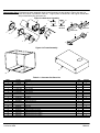
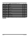
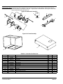
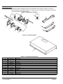
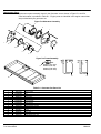
Replacement Parts . . . . . . . . . . . . . . . . . . . . . . . . . . . . . . . . . . . . . . . . . . . . . . . . . . . . . . . . . . . . . . . . . . . . . . . . . . . . .
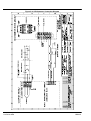
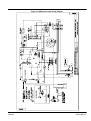
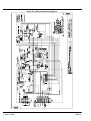
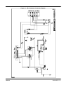
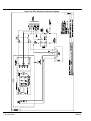
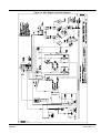
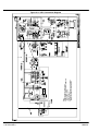
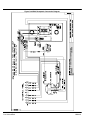
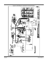
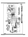
Wiring Diagrams . . . . . . . . . . . . . . . . . . . . . . . . . . . . . . . . . . . . . . . . . . . . . . . . . . . . . . . . . . . . . . . . . . . . . . . . . . . . . . .
Appendix B
Series AE10 . . . . . . . . . . . . . . . . . . . . . . . . . . . . . . . . . . . . . . . . . . . . . . . . . . . . . . . . . . . . . . . . . . . . . . . . . . . . . . . . . . . . . .
Operator Panel Configuration . . . . . . . . . . . . . . . . . . . . . . . . . . . . . . . . . . . . . . . . . . . . . . . . . . . . . . . . . . . . . . . . . . . .
Replacement Parts . . . . . . . . . . . . . . . . . . . . . . . . . . . . . . . . . . . . . . . . . . . . . . . . . . . . . . . . . . . . . . . . . . . . . . . . . . . . .
Wiring Diagrams . . . . . . . . . . . . . . . . . . . . . . . . . . . . . . . . . . . . . . . . . . . . . . . . . . . . . . . . . . . . . . . . . . . . . . . . . . . . . . .
Appendix C
Series AE11 . . . . . . . . . . . . . . . . . . . . . . . . . . . . . . . . . . . . . . . . . . . . . . . . . . . . . . . . . . . . . . . . . . . . . . . . . . . . . . . . . . . . . . .
Operator Panel Configuration . . . . . . . . . . . . . . . . . . . . . . . . . . . . . . . . . . . . . . . . . . . . . . . . . . . . . . . . . . . . . . . . . . . .
Replacement Parts . . . . . . . . . . . . . . . . . . . . . . . . . . . . . . . . . . . . . . . . . . . . . . . . . . . . . . . . . . . . . . . . . . . . . . . . . . . . .
Conversion from LPG to Natural Gas . . . . . . . . . . . . . . . . . . . . . . . . . . . . . . . . . . . . . . . . . . . . . . . . . . . . . . . . . . . . .
Wiring Diagrams . . . . . . . . . . . . . . . . . . . . . . . . . . . . . . . . . . . . . . . . . . . . . . . . . . . . . . . . . . . . . . . . . . . . . . . . . . . . . . .
Appendix D
Series AE25 . . . . . . . . . . . . . . . . . . . . . . . . . . . . . . . . . . . . . . . . . . . . . . . . . . . . . . . . . . . . . . . . . . . . . . . . . . . . . . . . . . . . . .
Operator Panel Configuration . . . . . . . . . . . . . . . . . . . . . . . . . . . . . . . . . . . . . . . . . . . . . . . . . . . . . . . . . . . . . . . . . . . .
Replacement Parts . . . . . . . . . . . . . . . . . . . . . . . . . . . . . . . . . . . . . . . . . . . . . . . . . . . . . . . . . . . . . . . . . . . . . . . . . . . . .
Wiring Diagrams . . . . . . . . . . . . . . . . . . . . . . . . . . . . . . . . . . . . . . . . . . . . . . . . . . . . . . . . . . . . . . . . . . . . . . . . . . . . . . .
ii Table of Contents
A-1
A-1
A-2
A-3
B-1
B-1
B-2
B-3
C-1
C-1
C-2
C-3
C-4
D-1
D-1
D-2
D-3
MN2415
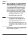
Section 1
Product Safety Information
Safety Notice
Be sure that you are completely familiar with the safe operation of this equipment. This
equipment may be connected to other machines that have rotating parts or parts that are
controlled by this equipment. Improper use can cause serious or fatal injury. Always
disconnect all electrical loads before starting the generator.
Installation and repair procedures require specialized skills with electrical generating equipment
and liquid cooled engine systems. Any person that installs or repairs this generator must have
these specialized skills to ensure that this generating unit is safe to operate. Contact Baldor for
repairs or any questions you may have about the safe installation and operation of this system.
The precaution statements are general guidelines for the safe use and operation of this
generator. It is not practical to list all unsafe conditions. Therefore, if you use a procedure that is
not recommended in this manual you must determine if it is safe for the operator and all
personnel in the proximity to the generator and connected loads. If there is any question of the
safety of a procedure please contact Baldor before starting or stopping the generator.
This equipment contains high voltages. Electrical shock can cause serious or fatal injury. Only
qualified personnel should attempt the start−up procedure or troubleshoot this equipment.
This equipment may be connected to other machines that have rotating parts or parts that are
driven by this equipment. Improper use can cause serious or fatal injury. Only qualified
personnel should attempt the start−up procedure or troubleshoot this equipment.
−
System documentation must be available to anyone that operates this equipment at all
times.
−
Keep non-qualified personnel at a safe distance from this equipment.
−
Only qualified personnel familiar with the safe installation, operation and maintenance
of this device should attempt start-up or operating procedures.
−
Always stop engine before making or removing any connections.
−
Always stop engine and allow it to cool before refueling.
Responsibility
When your generator is delivered, it becomes the responsibility of the owner/operator of the
generator set to prevent unsafe conditions and operation of the equipment. Some
responsibilities include (but are not limited to) the following:
1. It is the responsibility of the owner/operator of this generator to ensure that this
equipment is correctly and safely installed.
2. It is the responsibility of the owner/operator of this generator to ensure that this
equipment, when installed fully complies with all federal, state and local codes.
3. It is the responsibility of the owner/operator of this generator to ensure that any person
operating this equipment has been properly trained.
4. It is the responsibility of the owner/operator of this generator to ensure that any person
operating this equipment has access to all manuals and information required for the
safe use and operation of this equipment.
5. It is the responsibility of the owner/operator of this generator to ensure that it is properly
maintained and safety inspected at regular scheduled intervals.
6. It is the responsibility of the owner/operator of this generator to ensure that any person
who has not been trained on the safe use of this equipment does not have access to
this equipment.
Read This Manual Thoroughly
If you do not understand any concept, any procedure, any safety warning statement, any safety
caution statement or any portion of this manual, contact Baldor or your nearest authorized Baldor
representative. We are happy to make sure you understand the information in this manual so
that you can safely enjoy the full use of this generator.
MN2415
Product Safety Information 1-1
Symbols
This symbol is shown throughout the manual to indicate a connection to ground reference point.
Indicates a potentially hazardous situation which, if not avoided, could result in injury or death.
Indicates a potentially hazardous situation which, if not avoided, could result in injury or death.
Precaution Statements Used In This Manual
There are three classifications of precautionary statements used in this manual. The most critical
is a WARNING statement, then the Caution statement and the least critical is the Note
statement. The usage of each statement is as follows:
WARNING: Indicates a potentially hazardous situation which, if not avoided, could result in injury or
death.
Caution: Indicates a potentially hazardous situation which, if not avoided, could result in damage to
property.
Note:
Additional information that is not critical to the installation or operation.
IMPORTANT SAFETY INSTRUCTIONS
SAVE THESE INSTRUCTIONS − This manual contains important instructions for the generator that
should be followed during installation, operation and maintenance of the generator.
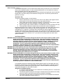
For ease of reading, the Warning statements are divided into four categories: Operation, Burn, Installation,
and Maintenance.
Operation
WARNING: Never operate this generator in a manner other than as described in this manual. Operation
in any manner not described in this manual should be considered unsafe and should not be
attempted. Never start the engine unless you have first verified that the installation and
operation of the generator are as described in this manual.
WARNING: Be sure that you are completely familiar with the safe operation of this equipment. This
equipment may be connected to other machines that have rotating parts or parts that are
controlled by this equipment. Improper use can cause serious or fatal injury.
WARNING: Exhaust fumes/gases are extremely dangerous and can cause severe illness or death. Never
breath exhaust fumes produced by a running engine. Only run the engine outdoors where
ventilation is plentiful. Exhaust gases contain carbon monoxide, a colorless, odorless and
extremely dangerous gas that can cause unconsciousness or death. Symptoms of carbon
monoxide poisoning include: dizziness, nausea, headaches, sleepiness, vomiting or
incoherence. If you or anyone else experiences these symptoms, get out into fresh air
immediately. Stop the engine and do not restart the engine until it has been inspected and if
necessary repaired or reinstalled in a well ventilated area.
WARNING: Hot exhaust gasses must never be directed toward anything that may catch fire or explode.
WARNING: This generator must not be used on or near any forest covered, brush covered, or grass
covered land unless the engine’s exhaust system is equipped with a spark arrestor. The
spark arrestor must be maintained in effective working order by the operator.
WARNING: Some parts of this generator rotate during operation. Rotating parts can present extreme
danger if clothing or body extremities are caught by the rotating part and can cause serious
or fatal injury. Never touch a part of the generator until the engine has been stopped and all
rotating parts are completely stopped. Also, disconnect the spark plug wires and battery
connection to prevent accidental engine rotation during servicing.
WARNING: Never move a generator set that is running. Loads should be connected and position secure
before starting the engine. Hazards are caused by moving a generator set that is running.
Continued on next page.
1-2 Product Safety Information
MN2415
Operation Warning Statements Continued
WARNING: Never connect or disconnect loads during operation. Always connect load circuits before
starting the engine and use external branch disconnects etc. to switch loads On/Off.
WARNING: Be sure that you understand how to stop the engine quickly in case of an emergency situation.
Become familiar with the controls and safety systems provided with this generator set.
WARNING: Always wear safety glasses with side shields and hearing protection when working near the
generator.
WARNING: Improper operation may cause violent motion of connected equipment. Be certain that
unexpected movement will not cause injury to personnel or damage to equipment.
WARNING: Never operate the generator set indoors or in a poorly ventilated area such as a tunnel or cave.
Exhaust fumes are extremely dangerous to all personnel that are in or in contact with that area.
WARNING: Never permit anyone to operate the generator without proper instructions. Be sure to keep a
copy of this manual with the generator so that all users can be properly informed of its safe
operation.
WARNING: Never allow children or pets to be in the area where the generator is running. The generator
and the equipment being powered by the generator may cause injury or death.
WARNING: Never operate the generator unless all guards, covers, shields and other safety items are
properly installed.
WARNING: Do not put hands, feet, tools clothing or other objects near rotating parts such as drive shaft,
pulley, belt etc. Rotating parts cause extremely dangerous situations because they can catch
loose clothing or extremities and cause serious or fatal injury.
WARNING: When operating this generator remain alert at all times. Never operate machinery when
physically or mentally fatigued, or while under the influence of alcohol, drugs or medication.
WARNING: Never operate the engine when the air cleaner is removed. An engine backfire can cause
serious burns.
WARNING: Never “jump start” a generator to start the engine. If the battery charge is insufficient to start
the engine, charge or replace the battery and try to restart. Jump starting a battery can cause
the battery to explode and cause severe injury or death to anyone in the area.
WARNING: High voltage is present whenever engine is running. Electrical shock can cause serious or
fatal injury. Never operate electrical equipment while standing in water, on wet ground or with
wet hands, feet or shoes or while barefoot.
WARNING: High voltage is present whenever the engine is running. Electrical shock can cause serious
or fatal injury. Always stop engine before connecting or disconnecting power cords or
external devices.
WARNING: Do not smoke near generator during operation or when close to fuel source. LPG and natural
gas fuels are flammable and can cause fire, explosions, injury or death.
WARNING: Keep generator at least three feet away from buildings and other structures.
WARNING: Keep generator away from flammable or hazardous materials (trash, rags, lubricants,
explosives, paints etc.) and grass or leaf build up.
WARNING: Keep a fire extinguisher near the generator while generator is in use. An extinguisher rated
“ABC” by the National Fire Protection Association is appropriate.
Burn
WARNING: Parts of this generator are extremely hot during and after operation. To prevent severe burns,
do not touch any part of the generator until you have first determined if the part is hot. Wear
protective clothing and after use allow sufficient time for parts to cool before touching any
part of the generator.
WARNING: Do not touch the hot exhaust parts or the high voltage spark plug or coil terminals of the
engine. Although spark plug voltages are not normally lethal, a sudden involuntary jerk of the
hand or body part caused by contact with high voltage or a hot surface can result in injury to
yourself or others.
WARNING: Engine coolant is under pressure and is near the boiling point of water when engine is hot.
Do not open the coolant system until the engine has completely cooled. Hot coolant can
cause severe burns and other injuries. When engine is cool, coolant level can be checked.
Continued on next page.
MN2415
Product Safety Information 1-3
Warning Statements Continued
Installation
WARNING: Installation and servicing of batteries is to be performed or supervised by personnel
knowledgeable of batteries and the required precautions. Keep unauthorized personnel away
from batteries.
WARNING: Disconnect the battery’s ground terminal before working in the vicinity of the battery or
battery wires. Contact with the battery can result in electrical shock when a tool accidently
touches the positive battery terminal or wire. The risk of such shock is reduced when the
ground lead is removed during installation and maintenance.
WARNING: An open bottom stationary engine generator set must be installed over noncombustible
materials and shall be located such that it prevents combustible materials from accumulating
under the generator set.
WARNING: Installation and repair procedures requires specialized skills with electrical generating
equipment and small engine systems. Any person that installs or performs repairs must have
these specialized skills to ensure that the generator set is safe to operate. Contact Baldor for
installation or repairs.
WARNING: Be sure all wiring complies with the National Electrical Code (NEC) and all regional and local
codes or CE Compliance. Improper wiring may cause a hazardous condition and exposure to
electrical hazards can cause serious injury or death.
WARNING: Be sure the system is properly grounded before applying power. Do not apply AC power before
you ensure that grounds are connected. Electrical shock can cause serious or fatal injury. NEC
requires that the frame and exposed conductive surfaces (metal parts) be connected to an
approved earth ground. Local codes may also require proper grounding of generator systems.
WARNING: Never allow the exhaust outlet to be positioned so that the exhaust gases are directed
towards any openings or air entry routes (doors, windows, vents, etc...) of an occupied
building. When discharging the hot exhaust gases out of the building do not direct them
towards anything that could catch fire or explode.
WARNING: Place protective covers over all rotating parts such as drive shaft, pulley, belt etc. Rotating
parts cause extremely dangerous situations because they can catch loose clothing or
extremities and cause serious or fatal injury.
WARNING: Unauthorized modification of a generator set may make the unit unsafe for operation or may
impair the operation of the unit. Never start a generator set that has been modified or
tampered with. Be sure that all covers and guards are properly installed and that the unit is
safe before starting the engine. If you are unsure, contact Baldor before starting the engine.
WARNING: When moving the generator, use reasonable caution. Be careful where you place fingers and
toes to prevent injury “Pinch Points”. Never try to lift a generator without a hoist or lift means
because they are heavy and bodily injury may result.
Warning: Never connect this generator to the electrical system of any building unless a licensed
electrician has installed an approved transfer switch. The national electrical code (NEC)
requires that connection of a generator to any electrical circuit normally powered by means of
an electric utility must be connected by means of approved transfer switch equipment to
isolate the electrical circuit from the utility distribution system when the generator is
operating. Failure to isolate the electrical circuits by such means may result in injury or death
to utility power workers due to backfeed of electrical energy onto the utility lines.
WARNING: Circuit overload protection must be provided in accordance with the National Electrical Code
and local regulations.
WARNING: Check Ground Fault Circuit Interrupt (GFCI) receptacles monthly by using the “Test” and
“Reset” buttons.
WARNING: Only a professional experienced technician should install a fuel supply system. LPG and
natural gas fuels are flammable and can cause fire, explosions, injury or death. Fuel supply
lines should be kept away from sharp objects to prevent rupture. Comply with all NFPA
regulations and local codes for shut−off valves, regulators, fuel line type, connectors etc.
WARNING: Have electrical circuits and wiring installed and checked by licensed electrician or qualified
technician. Electrical shock can cause serious or fatal injury.
WARNING: Incorrect installation of this generator set could result in property damage, injury or death.
Connection of the generator to its fuel source must be done by a qualified professional
technician or contractor.
Continued on next page.
1-4 Product Safety Information
MN2415
Warning Statements Continued
Maintenance
WARNING: Before servicing the generator set, be sure to disconnect the battery terminals to prevent
accidental engine rotation or starting.
WARNING: Disconnect the battery’s ground terminal before working in the vicinity of the battery or
battery wires. Contact with the battery can result in electrical shock when a tool accidently
touches the positive battery terminal or wire. The risk of such shock is reduced when the
ground lead is removed during installation and maintenance.
WARNING: Installation and servicing of batteries is to be performed or supervised by personnel
knowledgeable of batteries and the required precautions. Keep unauthorized personnel away
from batteries.
WARNING: A battery presents a risk of fire and explosion because they generate hydrogen gas.
Hydrogen gas is extremely explosive. Never jump start a battery, smoke in the area around
the battery or cause any spark to occur in the area around the battery.
WARNING: Do not mutilate the battery or dispose of a battery in a fire. The battery is capable of
exploding. If the battery explodes, electrolyte solution will be released in all directions.
Battery electrolyte solution is caustic and can cause severe burns and blindness. If
electrolyte contacts skin or eyes, immediately flush the area with water and seek medical
attention quickly.
WARNING: A battery presents a risk of electrical shock hazard and high short circuit current. Electrical
shock can cause serious or fatal injury. Never wear jewelry, watch or any metal objects when
in the area around the battery.
WARNING: The battery electrolyte is a dilute sulfuric acid that is harmful to the skin and eyes. It is
electrically conductive and corrosive. If electrolyte contacts the skin, flush the area
immediately with water and wash it off using soap and water. If electrolyte contacts the eyes,
immediately flush the eye thoroughly with water and seek medical attention quickly.
WARNING: Before cleaning, inspecting, repairing or performing any maintenance to the generator set,
always be sure the engine has stopped and that all rotating parts have also stopped. After
stopping, certain components are still extremely hot so be careful not to get burned. Before
servicing the generator set, be sure to disconnect the spark plug wires and the battery
terminals to prevent accidental engine rotation or starting.
WARNING: Engine coolant is under pressure and is near the boiling point of water when engine is hot.
Do not open the coolant system until the engine has completely cooled. Hot coolant can
cause severe burns and other injuries. When engine is cool, coolant level can be checked.
WARNING: Before servicing the generator set, be sure to disconnect the spark plug wires and the battery
terminals to prevent accidental engine rotation or starting.
WARNING: Inspect all wiring frequently and replace any damaged, broken or frayed wiring or wires with
damaged insulation immediately. Electrical shock can cause serious or fatal injury.
WARNING: Disconnect all electrical wires and load devices from generator power outlets before servicing
the generator. Electrical shock can cause serious or fatal injury. Always treat electrical
circuits as if they are energized.
WARNING: Check all fuel supply piping, and their connections monthly for fuel leaks. LPG and natural
gas fuels are flammable and can cause fire, explosions, injury or death. If a leak is found,
replace only with approved pipe or components.
Continued on next page.
MN2415
Product Safety Information 1-5
Caution Statements
Caution: Avoid installing the generator set beside heat generating equipment, or directly below water
or steam pipes or in the vicinity of corrosive substances or vapors, metal particles and dust.
Heat can cause engine problems to develop and unwanted substances can cause rust or
generator failure over time.
Caution: Do not apply high voltage to windings (do not start the generator) in a moisture−saturated
condition. Moisture can cause insulation breakdown, making it necessary to return the
generator to the factory for repair, and consequent expense and loss of time.
Caution: Use only original equipment or authorized replacement parts. Using the correct parts will
assure continued safe operation as designed.
Caution: Do not support the generator from the top of the frame or enclosure.
Caution: Do not tamper with or change the engine speed. Engine speed is factory set to produce the
correct voltage and output frequency.
Caution: Never operate the engine without a muffler. The engine is designed to have the correct
exhaust components installed and operating without these components can present a fire
hazard, cause excessive exhaust gases and cause damage to engine. Inspect muffler
periodically and replace if necessary.
Caution: The Programmable Output Contacts selection must agree with the external control wiring
prior to energizing the controller. Failure to do so may cause severe equipment damage.
Caution: This generator must have a battery installed for operation. The battery is used during starting
and during operation. If engine operation is attempted while the battery is removed, damage
to the engine’s electrical components may result.
1-6 Product Safety Information
MN2415
Section 2
General Information
Thank you for purchasing your Baldor Generator Set. This manual contains information you need to safely and efficiently
install and operate your generator set. During the preparation of this manual every effort was made to ensure the
accuracy of its contents. This manual describes only very basic engine information. A separate owner’s manual for the
engine is supplied with this unit for your use. Please refer to the engine manual for information relative to engine
operation, maintenance, recommendations and additional safety warnings.
Copyright Baldor { 2004. All rights reserved.
This manual is copyrighted and all rights are reserved. This document may not, in whole or in part, be copied or
reproduced in any form without the prior written consent of Baldor Electric Company, Inc.
Baldor Generators have earned the reputation of being high quality and dependable. We take pride in this fact and
continue to keep our quality standards high on our list of priorities. We are also constantly researching new technological
ideas to determine if they could be used to make our generator sets even better.
Baldor makes no representations or warranties with respect to the contents hereof and specifically disclaims any implied
warranties of fitness for any particular purpose. The information in this document is subject to change without notice.
Baldor assumes no responsibility for any errors that may appear in this document.
Limited Warranty
Baldor Generators will replace or repair free of charge any part or parts of the generator of their manufacture that are
defective in workmanship and materials for a period of time as set forth in the Warranty Period chart below. All Baldor
products requiring warranty service shall be transported or shipped freight pre−paid, at the risk of the party requiring
warranty service, to a Baldor Generator repair facility, or to Baldor Generators’ Customer Service Department in
Oshkosh, Wisconsin. Written notification of the alleged defect in addition to a description of the manner in which the
Baldor generator is used, and the name, address and telephone number of the party requiring warranty service must be
included. Baldor is not responsible for removal and shipment of the Baldor product to the service center or for the
reinstallation of the Baldor product upon its return to the party requiring warranty service. Problems with Baldor products
can be due to improper maintenance, faulty installation, non−Baldor additions or modifications, or other problems not due
to defects in Baldor workmanship or materials. If a Baldor Generator repair facility determines that the problem with a
Baldor product is not due to defects in Baldor workmanship or materials, then the party requesting warranty service will
be responsible for the cost of any necessary repairs. EXCEPT FOR THE EXPRESSED WARRANTY SET FORTH
ABOVE, BALDOR GENERATORS DISCLAIMS ALL OTHER EXPRESSED AND IMPLIED WARRANTIES INCLUDING
THE IMPLIED WARRANTIES OF FITNESS FOR A PARTICULAR PURPOSE AND MERCHANTABILITY. NO OTHER
WARRANTY, EXPRESSED OR IMPLIED, WHETHER OR NOT SIMILAR IN NATURE TO ANY OTHER WARRANTY
PROVIDED HEREIN, SHALL EXIST WITH RESPECT TO THE GOODS SOLD UNDER THE PROVISIONS OF THESE
TERMS AND CONDITIONS. ALL OTHER SUCH WARRANTIES ARE HEREBY EXPRESSLY WAIVED BY THE BUYER.
UNDER NO CIRCUMSTANCES SHALL BALDOR GENERATORS BE LIABLE OR RESPONSIBLE IN ANY MANNER
WHATSOEVER FOR ANY INCIDENTAL, CONSEQUENTIAL OR PUNITIVE DAMAGES, OR ANTICIPATED PROFITS
RESULTING FROM THE DEFECT, REMOVAL, REINSTALLATION, SHIPMENT OR OTHERWISE. This is the sole
warranty of Baldor Generators and no other affirmations or promises made by Baldor Generators shall be deemed to
create an expressed or implied warranty. Baldor Generators has not authorized anyone to make any representations or
warranties other than the warranty contained herein.
Warranty Period
Generator Series
Labor*
Parts
Portable Products (Premier, Powerchief,
DG Series, K Series)
Towable Products (TS)
1 Year
3 Years
3 Years or 3,000 Hours
Whichever comes first
POW’R LITE Light Towers
3 Years or 3,000 Hours Whichever comes first
Excluded from any warranty coverage regardless of
time period: Light Fixture, Lamps and Ballasts
3600 RPM Standby Systems
1 Year or 1,000 Hours
3 Years or 1,000 Hours
(Some AE Models)
Whichever comes first
Whichever comes first
1800 RPM Standby Systems
1 Year or 3,000 Hours
3 Years or 3,000 Hours
(Some AE Models, DLC, GLC)
Whichever comes first
Whichever comes first
Industrial Standby Systems
1 Year or 1,000 Hours
2 Years or 1,000 Hours
Whichever comes first
Whichever comes first
Industrial Prime Power Systems
1 Year or 1,000 Hours
1 Year or 1,000 Hours
Whichever comes first
Whichever comes first
International
1 Year or 1,000 Hours
1 Year or 1,000 Hours
Whichever comes first
Whichever comes first
*For products covered under labor coverage, travel expenses will be allowed up to 7 hours straight labor or 300 miles,
whichever occurs first and only applies to permanently wired and mounted products (AE, DLC, GLC, IDLC).
No warranty registration card is necessary to obtain warranty on Baldor Generators.
You must save the purchase receipt. Proof of purchase, date, serial number and model number will be required for all
portable and Towable products to qualify for any warranty consideration.
For all other products, a start−up inspection form/warranty registration must be completed in its entirety and submitted to
Baldor Generators within 30 days of start−up to qualify for any warranty consideration.
MN2415
1 Year or 3,000 Hours
Whichever comes first
1 Year or 3,000 Hours
Whichever comes first
General Information 2-1
2-2 General Information
MN2415
Section 3
Receiving & Installation
Receiving & Inspection When you receive your generator, there are several things you should do immediately.
1.
Observe the condition of the shipping container and report any damage immediately to
the commercial carrier that delivered your system.
2. Verify that the part number of the system you received is the same as the part number
listed on your purchase order.
3. If the system is to be stored for several weeks before use, be sure that it is stored in a
location that conforms to published storage temperature and humidity specifications.
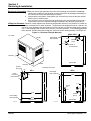
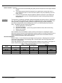
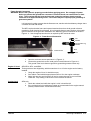
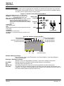
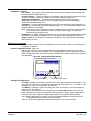
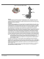
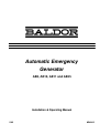
Lifting the Generator When lift or hoist equipment is used to lift the generator and move it to position, be careful not
to contact overhead wires or other obstacles. The generator can weigh as much as 1,500 lbs. Be
sure lift or hoist equipment has appropriate tires for the terrain to avoid becoming stuck or tipping
over. If the shipping pallet is intact, use a fork lift to move the generator. If the shipping pallet has
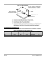
been removed, use two steel pipes through the “Lift Point” holes to lift the generator. See Figure 3-1.
Figure 3-1 Generator Lifting & Mounting
AE8 & AE10
Not To Scale
2.63
Four mounting
holes 0.38" dia.
Length
8.88
8.88
Electrical
Stub Up
7.75
Fuel Inlet on
Horizontal Surface
Height
44.50
Lift Point
(Alternator End)
Width
Lift Point
29.00
Thru Base
Stub Up Area
All dimensions are in inches.
1.50
Stub Up
Access Panel
(Fuel & Electrical)
1.50
AE11
AE25
Six mounting
holes 0.410" dia.
30.00
6.00
4.52
24.00
42.00
3.19
Fuel Inlet
Zone
46.00
28.00
24.00
26.14
Four mounting
holes 0.38" dia.
LT0143A30
MN2415
29.29
(Alternator End)
30.29
72.00
8.12
3.19
Electrical
Stub Up
20.94
(Alternator End)
LT0143A02
31.25
Receiving & Installation 3-1
Physical Location The mounting location of the system is important. It should be installed in an area that is
protected from direct harmful gases or liquids, dust, metallic particles, shock and vibration.
It should be installed in an outdoor location so the exhaust fumes are vented to the atmosphere.
WARNING: An open bottom stationary engine generator set must be installed over noncombustible
materials and shall be located such that it prevents combustible materials from accumulating
under the generator set.
Outdoor Location with Baldor Supplied Enclosure
If the generator is installed outdoors there should not be a cooling problem. The factory installed
enclosure is designed to keep out undesirable weather elements while providing cooling and
ventilation. It should be installated on a concrete pad with at least thirty−six (36) inches
clearance on all sides for air flow.
1. For effective cooling and maintenance, the system should be installated on a concrete pad
with at least thirty−six (36) inches clearance on all sides for air flow and service access.
2. Installation should prevent water levels from reaching the generator. Drainage must be
adequate to keep concrete pad free from standing water.
3. Installation should prevent obstructions by buildup of leaves, grass, sand, snow, etc. If
these items pose a problem, consider building a small fence or other break to protect
the unit from accumulation of debris.
Indoor Location Open Frame Configuration
When the Generator is installed in a building it is essential to provide:
1. Adequate control and exhausting of the heated air.
2. An adequate and constant supply of incoming cooling air.
3. Adequate control and discharge of the engine’s hot exhaust gases.
4. Adequate ventilation of the building when the engine shuts down.
Several other factors should be carefully evaluated when selecting a location for installation:
1. For effective cooling and maintenance, the system should be mounted on a flat, smooth,
non-flammable level surface. A concrete pad is ideal and provides a secure installation.
2. Installation should prevent water levels from reaching the generator. Drainage must be
adequate to keep concrete pad free from standing water.
3. Installation should prevent obstructions by buildup of leaves, grass, sand, snow, etc. If
these items pose a problem, consider building a small fence or other break to protect
the unit from accumulation of debris.
4. Installation should place the generator as close as possible to the fuel supply and
transfer switch.
5. At least forty−eight (48) inches clearance must be provided on all sides for air flow.
6. Maximum Ambient temperature is 122°F (50°C).
Engine Cooling
A sufficient flow of clean, cool air is required for combustion and to dissipate the heat produced
by the engine. Approximately 60% of the heat value of the fuel used is given off as heat (cooling
air and exhaust).
The air that will cool the engine must be brought in from outside the building. A sufficient air−flow
of rate “Cubic Feet per Minute” (CFM) will allow the incoming fresh air to cool the engine. This
requires a power ventilation system of sufficient CFM to be located at the highest possible point
of the building to exhaust hot air and draw in cool fresh air. For 8−12KW we recommend an
exhaust fan of at least 2000 CFM.
Note: The exhaust fan must not be located where it could easily become blocked by leaves,
snow, water, debris, etc.
3-2 Receiving & Installation
MN2415
Indoor Location Continued
It is recommended that the cool air intake have at least three (3) times the cross−sectional area
of the power ventilation system. It is also recommended that the cool air intake be located as
close as possible to the top of the generator set.
The exhaust fan must be connected to the AC power terminals of the generator set so that when
the generator set starts it will provide immediate cooling air flow. The fan will operate until the
generator set stops.
Ventilation Test
To test the ventilation system, do the following:
1. Place a thermometer as close as you can to the cool air intake of the engine’s blower
housing but do not let the thermometer touch any material surface.
2. Place another thermometer outside the building or compartment in the open air. (Keep
the thermometer out of direct sunlight or any other heat sources).
3. Run the engine under maximum load for an extended period of time (at least one hour).
4. The temperature difference between the two should not exceed 15 degrees F.
Note that opening any door, window or other opening can upset the air−flow pattern and result in
a significant reduction in the cooling air−flow across the generator set. This may result in
overheating, fire, or explosion. To find out if this is true with your specific application run the
Ventilation Test with all doors and windows closed. Then repeat this test with different doors and
windows open, and eventually with all the windows and doors open. If any of these tests result in
a temperature difference in excess of 15° F, you must not run the generator set under those
specific conditions.
Hot Exhaust Gasses
WARNING: Exhaust fumes/gases are extremely dangerous and can cause severe illness or death. Never
breath exhaust fumes produced by a running engine. Only run the engine outdoors where
ventilation is plentiful. Exhaust gases contain carbon monoxide, a colorless, odorless and
extremely dangerous gas that can cause unconsciousness or death. Symptoms of carbon
monoxide poisoning include: dizziness, nausea, headaches, sleepiness, vomiting or
incoherence. If you or anyone else experiences these symptoms, get out into fresh air
immediately. Stop the engine and do not restart the engine until it has been inspected and if
necessary repaired or reinstalled in a well ventilated area.
WARNING: Hot exhaust gasses must never be directed toward anything that may catch fire or explode.
WARNING: Never allow the exhaust outlet to be positioned so that the exhaust gases are directed
towards any openings or air entry routes (doors, windows, vents, etc...) of an occupied
building. When discharging the hot exhaust gases out of the building do not direct them
towards anything that could catch fire or explode.
WARNING: Exhaust fumes/gases are extremely dangerous and can cause severe illness or death. Never
breath exhaust fumes produced by a running engine. Only run the engine outdoors where
ventilation is plentiful. Exhaust gases contain carbon monoxide, a colorless, odorless and
extremely dangerous gas that can cause unconsciousness or death. Symptoms of carbon
monoxide poisoning include: dizziness, nausea, headaches, sleepiness, vomiting or
incoherence. If you or anyone else experiences these symptoms, get out into fresh air
immediately. Stop the engine and do not restart the engine until it has been inspected and if
necessary repaired or reinstalled in a well ventilated area.
It is extremely important to discharge engine exhaust gasses away from the engine and out of
the building. The direction of the discharged hot air and hot exhaust gases is important as they
have the potential to create brown spots on the lawn. In extreme cases this extremely hot air
could cause dried grass or other debris to ignite.
Guidelines for Exhaust System
1. It is extremely important that you do not allow the hot exhaust gases to re−circulate into
the engine’s cooling air intake.
2. The exhaust system is subject to the engine’s vibration and it must therefore be solidly
secured to reduce mechanical stress and the potential for breakage.
3. The engine’s exhaust system is the hottest component of the installation and extreme
care and considerations must be given to it.
MN2415
Receiving & Installation 3-3
Indoor Location Continued
4. Keep all fuel and its associated piping away from all components of the engine exhaust
system.
5. The exhaust system should be inspected on a regular basis to assure there are no
toxic exhaust gas leaks. In some areas this inspection may be provided by your local
public service.
6. A carbon monoxide tester may be installed to detect the presence of the deadly gas
during times when you are in the building with the engine running (during testing or
maintenance).
The generator is completely assembled, tested and adjusted at the factory before it is shipped to
you. The procedures presented in this manual are suggestions and it is the responsibility of the
Owner/Operator to arrange for these procedures to be performed by licensed contractors
according to all applicable codes including local codes for your Municipality/City/County and
State. Installation generally includes the following:
1. Secure Generator to concrete pad.
2. Connect Fuel Supply.
3. Electrical Connections − power wiring (optional transfer switch) and control wiring.
4. Battery (not included).
5. Ground Connection.
After installation, the post installation checks must be performed prior to starting the engine.
After these checks have been performed and the system operation is verified to be good, refer to
Section 6 Maintenance for periodic checks that must be performed at scheduled intervals to
ensure continued operation with minimal problems.
Secure the Generator
Refer to Table 3-1 for the dimensions and weight of each generator. Mounting bolts in the base
frame secure the generator to the shipping pallet. Remove these bolts, lift the generator and
remove the shipping pallet.
Secure the generator to the concrete pad using anchor hardware (not provided). See Figure 3-1.
Anchor bolts must be long enough to extend through the generator mounting frame.
Table 3-1 Physical Dimensions
Installation
Generator
Model
AE8−E/O
AE10−E/O
AE11−E
AE25−E−NG
AE25−E−LP
Height
Width
Length
36.75
36.75
30.50
34.00
34.00
29.00
29.00
30.375
31.5.0
31.5.0
44.5
44.5
46
72
72
3-4 Receiving & Installation
Weight
Open
255 lbs.
316 lbs.
Enclosed
463 lbs.
509 lbs.
468 lbs.
1450 lbs.
1450 lbs.
MN2415
Fuel Connections
The AE Series generators will run on Natural Gas or LPG (Liquid Propane Gas). If natural gas
supply is used, follow the “Natural Gas Connections” procedure. If LPG supply is used, follow
the “LP Gas Connections” procedure. Table 3-2 defines the flow rate required for each fuel type.
Note: The AE25 must be ordered for use with Natural gas or LPG.
Table 3-2 Fuel Consumption Natural and LPG
Generator Model
AE8
AE10
AE11
AE25
Required Flow Rate (cubic feet per hour)
Natural Gas
LPG
160
64
200
72
200
72
400
159
Pressure
oz. (inches
i h water
t column)
l
)
6 oz (11)
6 oz (11)
4 oz. (7)
6 oz (11)
General Considerations
1. A generator set needs the engine to deliver 2 hp of energy to the alternator for every
1000 watts of electric output power (example: an 8000 watt generator needs the engine
to deliver 16 hp of energy to the generator end).
2. An engine needs 10,000 BTU’s of fuel energy per horsepower of engine power to
provide a sufficient supply of fuel (example: a 16 Hp engine needs 160,000 BTU’s of
fuel energy for it to work properly). This fuel must be supplied to the regulator on the
generator set at a pressure indicated in Table 3-2. To achieve this pressure in an L.P.
System, you will normally have to reduce the tank pressure by means of a primary
regulator or a regulator system of 2 or more regulators.
3. There are 2,516 BTU’s in one cubic foot of Propane (LP Fuel).
There are 1,096 BTU’s in one cubic foot of Natural Gas.
4. There are 36.39 cubic feet in one gallon of Propane.
There are 57.75 cubic feet in one gallon of Natural Gas.
5. There are 8.58 cubic feet per pound of Propane.
There are 23.56 cubic feet per pound of Natural Gas.
6. When installing the piping for the gaseous fuel supply please refer to the pipe chart in
Tables 3-3 and 3-4 to be sure you are using piping of significantly large size to deliver
the necessary amount of fuel.
7. If copper tubing is used, it should be “K” or “L” having a minimum wall thickness of
0.032 inches. Black Iron Pipe is recommended but follow building codes for your area.
The following pamphlets are available from:
National Fire Protection Association (NFPA) P.O. Box 9101 Quincy, MA 02269
No. 37 − Combustion Engines
No. 54 − Gaseous Appliances and piping
No. 58 − Storage and handling LPG
Example: Determining Pipe Size for Natural Gas
An AE8 has a 16Hp engine. For Natural Gas fuel, determine the supply pipe size for 60 feet run.
16 x 10,000 = 160,000 BTU’s / per hour for proper operation.
160, 000
+ 146 cubic feet per hour.
1, 096
From Table 3-4, a 60 foot run requires a minimum 1” pipe at full engine load.
MN2415
Receiving & Installation 3-5
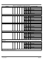
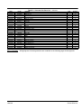
Natural Gas Connections
The incoming pressure must be as indicated in Table 3-2.
Note: Almost all operation problems are related to the installation techniques used.
Do Not guess, be sure pipe size is adequate for required flow rate.
Table 3-3 Natural Gas Flow Rate (Cubic Feet per Hour) per Pipe Length
Pipe
Length
(Feet)
15
30
45
60
75
90
105
120
150
180
210
240
270
300
Iron Pipe Size
1/ ″
2
3/ ″
4
73
50
41
37
165
115
95
83
74
67
63
1.
2.
3.
1″
1−1/4″
1−1/2″
2″
2−1/2″
3″
4″
6″
8″
332
232
191
166
149
137
126
115
105
96
89
722
515
418
366
332
298
274
260
233
216
197
183
171
164
1174
818
673
587
524
433
433
404
366
337
308
289
274
260
2386
1712
1419
1241
1077
962
885
827
750
693
635
596
558
524
3704
2646
2213
1924
1684
1501
1376
1289
1174
1077
991
933
875
827
6253
4521
3752
3319
2886
2597
2357
2213
2011
1876
1712
1616
1520
1433
13352
9331
7600
6542
5772
5291
4906
4618
4185
3848
3559
3357
3127
2886
37229
26330
22462
18595
16652
15200
14064
13160
11775
10736
9937
9235
8658
8177
53728
43867
37999
33959
31025
28715
26859
24050
21934
20298
18990
17903
16998
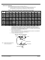
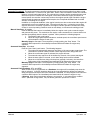
Connect the proper size gas pipe at the input to the Natural Gas regulator. Connect
the Natural Gas pipe line shown in Figure 3-2 using the correct size pipe for the
required flow rate and length of pipe. Refer to Table 3-3 for pipe size. Be certain that
all connections are sealed and no leaks are present. The installer must ensure that all
gas connections comply with all building codes.
Verify Fuel Supply Pressure
Prior to initial operation of generator, verify that fuel system pressure is as indicated in
Table 3-2 and fuel pipe sizes comply with Table 3-3.
Proceed to Electrical Connections.
Figure 3-2 Gas Line Connections
Carburetor
Air Cleaner
Gasket
Regulator
Solenoid, Fuel Lock
Note:
Regulator shown for Natural Gas only.
For LPG, mount upside down.
Inlet Connection
Mounting Bracket
3-6 Receiving & Installation
MN2415
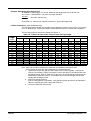
Example: Determining Pipe Size for LPG
An AE8 has a 16Hp engine. For LP fuel, determine the supply pipe size for 60 feet run.
16 x 10,000 = 160,000 BTU’s / per hour for proper operation.
160, 000
+ 63.5 cubic feet per hour.
2, 516
From Table 3-4, a 60 foot run requires a minimum 1” pipe at full engine load.
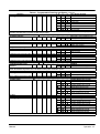
LP Gas Connections (vapor withdrawal only)
The LPG connections should only be made if your generator is setup to run on LPG. If it is setup
to run on Natural Gas, contact your Baldor representative and do not continue with installation.
The incoming pressure must be as indicated in Table 3-2.
Table 3-4 LP Gas Flow Rate (Cubic Feet per Hour) per Pipe Length
Pipe
Length
(Feet)
15
30
45
60
75
90
105
120
150
180
210
240
270
300
Iron Pipe Size
1/ ″
2
3/ ″
4
1″
1−1/4″
1−1/2″
2″
2−1/2″
3″
4″
6″
8″
48
33
27
24
109
76
63
54
49
44
41
218
153
126
110
98
89
83
76
69
63
58
475
339
275
241
218
196
180
171
153
142
130
120
113
108
772
538
443
386
345
310
285
266
241
222
202
190
180
171
1570
1127
934
817
709
633
582
544
494
456
418
393
367
345
2437
1741
1456
1266
1108
987
905
848
772
709
652
614
576
544
4115
2975
2469
2184
1899
1709
1551
1456
1323
1234
1127
1063
1000
943
8786
6140
5001
4304
3798
3482
3228
3038
2754
2532
2342
2209
2057
1899
24497
17325
14781
12236
10957
10001
9254
8659
7748
7064
6439
6077
5697
5381
50007
35353
28865
25004
22345
20414
18895
17673
15825
14432
13356
12405
11780
11179
Note: Almost all operation problems are related to the installation techniques used.
Do Not guess, be sure pipe size is adequate for required flow rate.
1. Connect the proper size gas pipe at the input to the LP Gas regulator. Connect the
LPG pipe line shown in Figure 3-2 using the correct size pipe for the required flow rate
and length of pipe. Refer to Table 3-4 for pipe size. Be certain that all connections are
sealed and no leaks are present. The installer must ensure that all gas connections
comply with all building codes.
2. Verify Fuel Supply Pressure
Prior to initial operation of generator, verify that fuel system pressure is as indicated in
Table 3-2 and fuel pipe sizes comply with Table 3-4.
3. Proceed to Electrical Connections.
MN2415
Receiving & Installation 3-7
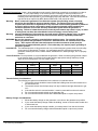
Electrical Connections Class 1 wiring methods must be used for field wiring connections to terminals of a class 2
circuit. It is the responsibility of the owner/operator to arrange for these procedures to be
performed by a licensed electrical contractor and ensure conformance to all applicable codes
including local codes peculiar to your municipality/city/county and state. Wire size and insulation
type should be as required by NEC (National Electrical Code) and local codes.
Warning: Never connect this generator to the electrical system of any building unless a licensed
electrician has installed an approved transfer switch. The national electrical code (NEC)
requires that connection of a generator to any electrical circuit normally powered by means of
an electric utility must be connected by means of approved transfer switch equipment to
isolate the electrical circuit from the utility distribution system when the generator is
operating. Failure to isolate the electrical circuits by such means may result in injury or death
to utility power workers due to backfeed of electrical energy onto the utility lines.
Warning: Incorrect installation of this generator set could result in property damage, injury or death.
Connection of the generator to its fuel source must be done by a qualified professional
technician or contractor.
WARNING: Be sure the system is properly grounded before applying power. Do not apply AC power
before you ensure that grounds are connected. Electrical shock can cause serious or fatal
injury. NEC requires that the frame and exposed conductive surfaces (metal parts) be
connected to an approved earth ground. Local codes may also require proper grounding of
generator systems.
Intended Use The intended purpose of this generator set is to provide emergency power when the main utility
power supply is interrupted. Therefore, it is important that all the wiring that connects the
generator set with your house, transfer switch, distribution box, battery charger, etc. be properly
installed.
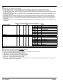
Circuit Protection Circuit protection is not provided with the generator. When connecting the generator output
to an electrical load, a UL listed circuit breaker with the appropriate ratings shall be provided
within 25 feet of the genset. Use only copper wires.
Generator Rating
Kilowatt (kW)
Catalog No.
Rating
AE8
8
AE10
10
AE11
11
AE25
25
1 Phase VAC
120/240
120/240
120/240
120/240
Input Breaker
1 Phase
3 Phase VAC
Amps
120/240/480
120/240/480
120/240/480
120/240/480
3 Phase
Amps
Transfer Switch Considerations
The following are general considerations for the safe use of a transfer switch:
1. The transfer switch should be located inside the building near the main breaker box or
the disconnect box.
2. The transfer switch must be kept away from any location that might allow water to get
on it.
3. If the transfer switch is mounted outside, it must be protected from the environment.
4. Do not mount the transfer switch on the generator set.
5. Do not mount the transfer switch where flammable liquids or vapors are present.
Battery Charger Considerations
1. Mount the battery charger on the generator or as close to the generator as possible.
2. If you mount the battery charger inside the building, mount it near the main breaker box
or disconnect box.
3. If you mount the battery charger outside, you must protect it from the environment.
4. Do not mount the battery charger where flammable liquids or vapors are present.
3-8 Receiving & Installation
MN2415
General Wiring Considerations
1. Control wires and Power wires cannot be located in the same conduit (NEC Article 725).
2. When routing the interface wiring, do not route it up against anything that could cut or
chafe the wiring. do not route the wire up against any hot or potentially hot object.
3. Make sure that all the electrical components (generator set, transfer switch, battery
charger, etc.) share a common hardwired ground.
4. Check with your local building inspector to determine what you must do to comply with
the local regulations for grounding of this type of permanent installation.
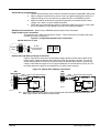
AE8 Electrical Connections Applies only to AE8 Enclosed and Open Series Generators
Single Phase Power Connections
The generator has a 240V single phase AC output. These connections are made at the power
terminal box shown in Figure 3-3.
Figure 3-3 Single Phase Output Power Connections
AE8 with Enclosure or Open
1
N
4
Generator
Output
L1
N
L2
Customer
AC Output Connections
(to Transfer Switch)
L1 to N
L2 to N
L1 to L2
120VAC
120VAC
240VAC
BW0120D
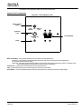
Remote Start and Battery Charger Connections
Figure 3-4 shows the connections for the battery charger and the remote start contacts of the
transfer switch. When the Remote Start Switch is closed, the generator will start. The unit will
remain running until this connection is opened. When the Remote Start Switch is opened, the
control circuits allow the engine to run for approximately 60−90 seconds before it shuts off. This
time delay allows the engine to run unloaded to cool down before stopping.
Figure 3-4 Remote Start & Battery Connections
AE8
with Enclosure
R1
R2
Batt+
Batt−
D1
D2
16AWG Customer Provided Optional Equipment
Twisted Pair Wire
Remote Start Switch
AE8
Open
Customer Provided Optional Equipment
16AWG
Twisted Pair Wire
Remote Start Switch
(Close to Start)
Out+
Out−
(Close to Start)
Out+
Out−
Battery
Charger
+
To 120VAC
(Shore Power)
BW0183D
Battery
Charger
−
Battery
To 120VAC
(Shore Power)
BW0120D
Note: Connect DK1 and DK2 of the battery charger go to the D1 and D2 terminals of the terminal block if a Master Control Systems Inc.
Battery charger is installed. DK1 and DK2 are not polarity sensitive.
MN2415
Receiving & Installation 3-9
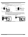
AE10 Electrical Connections Applies only to AE10 Enclosed and Open Series Generators
Single Phase Power Connections
The generator has a 240V single phase AC output. These connections are made at the power
terminal box shown in Figure 3-5.
Figure 3-5 Single Phase Output Power Connections
AE10 Open
AE10 with Enclosure
BW0201D
1
N
4
Generator
Output
L1
N
L2
Customer
AC Output Connections
(to Transfer Switch)
L1 to N
L2 to N
L1 to L2
120VAC
120VAC
240VAC
BW0333D
Generator
Output
To Frame
L1
N
L2
1
N
4
G
Customer
AC Output Connections
(to Transfer Switch)
L1 to N
L2 to N
L1 to L2
Note: G and N are internally
tied to Frame Ground.
120VAC
120VAC
240VAC
Remote Start and Battery Charger Connections
Figure 3-6 shows the connections for the battery charger and the remote start contacts of the
transfer switch. When the Remote Start Switch is closed, the generator will start. The unit will
remain running until this connection is opened. When the Remote Start Switch is opened, the
control circuits allow the engine to run for approximately 60−90 seconds before it shuts off. This
time delay allows the engine to run unloaded to cool down before stopping.
Figure 3-6 Remote Start & Battery Connections
AE10
with Enclosure
R1
R2
Batt+
Batt−
D1
D2
16AWG Customer Provided Optional Equipment
Twisted Pair Wire
Remote Start Switch
Customer Provided Optional Equipment
16AWG
Twisted Pair Wire
Remote Start Switch
(Close to Start)
Out+
Out−
(Close to Start)
Out+
Out−
Battery
Charger
BW0201D
To 120VAC
(Shore Power)
BW0333D
AE10
Open
+
Battery
Charger
−
Battery
To 120VAC
(Shore Power)
Note: Connect DK1 and DK2 of the battery charger go to the D1 and D2 terminals of the terminal block if a Master Control Systems Inc.
Battery charger is installed. DK1 and DK2 are not polarity sensitive.
3-10 Receiving & Installation
MN2415
AE11 Electrical Connections Applies only to AE11 Enclosed Series Generators
Single Phase Power Connections
The generator has a 240V single phase AC output. These connections are made at the power
terminal box shown in Figure 3-7.
Figure 3-7 Single Phase Output Power Connections
AE11 with Enclosure
TBP
Generator
Output
(Jumpered)
(Jumpered)
L1
L2
L3
N
N
G
G
L1
L2
Customer
AC Output Connections
(to Transfer Switch)
N
L1 to N
L2 to N
L1 to L2
120VAC
120VAC
240VAC
BW0459D
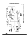
Remote Start and Battery Charger Connections
Figure 3-8 shows the connections for the battery charger and the remote start contacts of the
transfer switch. When the Remote Start Switch is closed, the generator will start. The unit will
remain running until this connection is opened. When the Remote Start Switch is opened, the
control circuits allow the engine to run for approximately 60−90 seconds before it shuts off. This
time delay allows the engine to run unloaded to cool down before stopping.
Figure 3-8 Remote Start & Battery Connections
AE11
with Enclosure
TBP
L1
N
G
Remote Start
Remote Start
Fuel Jumper
Fuel Jumper
16AWG Customer Provided Optional Equipment
Twisted Pair Wire
Remote Start Switch
Fuel Jumper
IN = Natural Gas
OUT = LPG
BW0459D
(Close to Start)
Out+
Out−
+
Battery
Charger
−
Battery
To 120VAC
(Shore Power)
Note: Remove Fuel Jumper
if LP Gas is used.
MN2415
Receiving & Installation 3-11
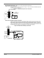
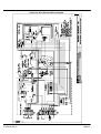
AE25 Electrical Connections Applies only to AE25 Enclosed Series Generators
Single Phase Power Connections
The generator has a 240V single phase AC output. These connections are made at the power
terminal box shown in Figure 3-9.
Figure 3-9 Single Phase Output Power Connections
AE25 with Enclosure (Natural Gas or LPG)
GND
Load
N
L1
L2
L1 to N
L2 to N
L1 to L2
Customer
AC Output Connections
(to Transfer Switch)
120VAC
120VAC
240VAC
Remote Start and Battery Charger Connections
Figure 3-10 shows the connections for the battery charger and the remote start contacts of the
transfer switch. When the Remote Start Switch is closed, the generator will start. The unit will
remain running until this connection is opened. When the Remote Start Switch is opened, the
control circuits allow the engine to run for approximately 60−90 seconds before it shuts off. This
time delay allows the engine to run unloaded to cool down before stopping.
Figure 3-10 Remote Start & Battery Connections
AE25 with Enclosure (Natural Gas or LPG)
R2 R1
TB1
16AWG
Twisted Pair Wire
Customer Provided Optional Equipment
Out+
Out−
Remote Start Switch
(Close to Start)
3-12 Receiving & Installation
+
Battery
Charger
−
Battery
To 120VAC
(Shore Power)
MN2415
Frame Ground Connection
WARNING: Be sure the system is properly grounded before applying power. Do not apply AC power
before you ensure that grounds are connected. Electrical shock can cause serious or fatal
injury. NEC requires that the frame and exposed conductive surfaces (metal parts) be
connected to an approved earth ground. Local codes may also require proper grounding of
generator systems.
It is important for safety reasons that the Generator set, transfer switch and battery charger share
a common Ground and neutral.
The NEC requires that the frame and exposed metal surfaces be at local ground reference
potential to avoid electrical shock hazard. A local ground reference may require a driven earth
ground conductor at the generator installation site. Make the ground connection as shown in
Figure 3-11. Use the appropriate size wire as required by NEC and local codes.
Figure 3-11 Frame Ground Connection
Nut
Washer
Ground Wire Lug
Washer
Earth Ground
Stud
Frame
1.
2.
Open the enclosure access panel door 2 ( Figure 3-1).
Connect the ground wire to the “earth ground” terminal shown in Figure 3-11.
This ground is the local reference ground to ground the generator frame only.
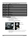
Engine Oil Level
AE8, AE10, AE11, and AE25
These generators are shipped dry, which means there is no oil in the engine and no battery
installed.
1. Check the engine oil level, it should be empty.
2. See Table 3-5 and add the appropriate amount of oil to the engine crankcase.
3. Add a little at a time and check the oil level to ensure that you do not overfill the
crankcase. Stop adding oil when the oil level reaches the full line.
Coolant Level
AE25 only
1. Check the coolant level while the engine is cold, it should be full.
2. If the coolant level is low, add some coolant as recommended in the engine manual
(usually a 50/50 mixture of antifreeze and water).
MN2415
Receiving & Installation 3-13
Caution:
This generator must have a battery installed for operation. The battery is used during starting
and during operation. If engine operation is attempted while the battery is removed, damage
to the engine’s electrical components may result.
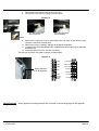
Battery Connections AE8, AE10, AE11, and AE25. The generator is shipped with no battery installed.
WARNING: Installation and servicing of batteries is to be performed or supervised by personnel
knowledgeable of batteries and the required precautions. Keep unauthorized personnel away
from batteries.
WARNING: Do not dispose of battery or batteries in a fire. The battery is capable of exploding. If the
battery explodes, electrolyte solution will be released in all directions. Battery electrolyte
solution is caustic and can cause severe burns and blindness. If electrolyte contacts skin or
eyes, immediately flush the area with water and seek medical attention quickly.
WARNING: Do not mutilate the battery . The battery contains electrolyte solution which is caustic and
can cause severe burns and blindness. If electrolyte contacts skin or eyes, immediately flush
the area with water and seek medical attention quickly.
WARNING: A battery presents a risk of electrical shock hazard and high short circuit current.
The following precautions are to be followed when working on batteries:
1. Remove watches, rings, necklaces and all other metal objects.
2. Use tools with insulated handles.
3. Wear rubber gloves and boots.
WARNING: The battery electrolyte is a dilute sulfuric acid that is harmful to the skin and eyes. It is
electrically conductive and corrosive.
The following precautions are to be followed when working on batteries:
1. Wear full eye protection (safety glasses or goggles) and protective clothing.
2. Where electrolyte contacts the skin, flush the area immediately with water and wash it
off using soap and water.
3. Where electrolyte contacts the eyes, immediately flush the eye thoroughly with water
and seek medical attention quickly.
4. Spilled electrolyte is to be washed down with an acid neutralizing agent. A common
practice is to use a solution of one pound (500 grams) bicarbonate of soda to one
gallon (four liters) of water. The bicarbonate solution is to be added until evidence of
reaction (foaming) has ceased. The resulting liquid is to be flushed with water and the
area dried.
WARNING: A battery presents a risk of fire because they generate hydrogen gas. Hydrogen gas is
extremely explosive. Never jump start a battery, smoke in the area around the battery or
cause any spark to occur in the area around the battery.
The following precautions are to be followed when working on batteries:
1. Do not smoke when near batteries.
2. Do not cause flame or spark in battery area.
3. Discharge static electricity from body before touching batteries by first touching a
grounded metal surface.
WARNING: Disconnect the battery’s ground terminal before working in the vicinity of the battery or
battery wires. Contact with the battery can result in electrical shock when a tool accidently
touches the positive battery terminal or wire. The risk of such shock is reduced when the
ground lead is removed during installation and maintenance.
Procedure:
The correct type battery must be installed in the battery compartment provided, see Table 3-5.
Installation and servicing of batteries is to be performed or supervised by personnel
knowledgeable of batteries and the required precautions.
Keep unauthorized personnel away from batteries.
1. Open access doors and locate battery tray.
2. Place the correct battery (see Table 3-5) on the tray.
3. Install the Battery Hold Down Bar and Rods as shown in Figure 3-12.
a. Place the bent end of the Battery Hold Down Rod through the hole in the Battery Tray.
b. Place the threaded end of the Battery Hold Down Rod through the hole in the
Battery Hold Down Bar and secure with flat washer, lock washer and nut.
c. Repeat steps 3a and 3b for the other Battery Hold Down Rod.
3-14 Receiving & Installation
MN2415
Figure 3-12 Battery Installation
The + and − terminals of your battery may
be different than shown. Be sure that the
Positive lead is connected to the positive
(+) terminal of your battery.
Washers & Nut
Battery Hold Down Bar
(Install away from terminals)
Battery
Washers & Nut
Battery Hold Down Rod
Battery Tray
4.
5.
6.
7.
8.
Connect the positive lead to the positive (+) battery terminal.
Connect the negative lead to the negative (−) battery terminal.
Do not lay tools or metal parts on top of batteries.
Connect charging source to the battery terminals.
Disconnect the battery’s ground terminal before working in the vicinity of the battery or
battery wires. Contact with the battery can result in electrical shock when a tool
accidently touches the positive battery terminal or wire. The risk of such shock is
reduced when the ground lead is removed during installation and maintenance.
Recommended Engine Oil and Battery Type
When replacing batteries, use only the recommended battery for your generator, see Table 3-5.
Table 3-5 Recommended Engine Oil and Battery Type
MODEL
AE8
AE10
AE11
AE25
MN2415
SUMMER
OIL
SAE. 30
SAE. 30
SAE. 30
SAE. 30
WINTER
OIL
5W/30
5W/30
5W/30
5W/30
OIL
CAPACITY
2.2 PTS
2.2 PTS
2.0 QTS
4.5 QTS
RECOMMENDED
BATTERY
Interstate SP−40
Interstate SP−40
Interstate SP−40
BCI Group 24
(AMPS) COLD
CRANKING
340
340
340
750
Receiving & Installation 3-15
Post Installation Checks
When the initial installation is complete, these checks must be performed before starting the
engine. These checks are not required before each start, only after the initial installation.
Caution: Do not apply high voltage to windings (do not start the generator) in a moisture−saturated
condition. Moisture can cause insulation breakdown, making it necessary to return the
generator to the factory for repair, and consequent expense and loss of time.
Note: These precautions are especially necessary in locations such as seaboard installations
and other high humidity areas. Some installations will be in atmospheres that are much
more corrosive than others. Prevention of a failure is better than being forced to make a
repair.
1. Generators that have been in transit or storage for long periods may be subjected to
extreme temperature and moisture changes. This can cause excessive condensation,
and the generator windings should be thoroughly dried before bringing the generator
up to full nameplate voltage. If this precaution is not taken, serious damage to the
generator can result.
2. Verify that the transfer switch is in Utility Power mode. No power must be present at
the generator or transfer switch connections. Verify with a voltmeter.
3. Verify that the engine starting battery negative (−) lead) is disconnected so accidental
starting is not possible.
4. Verify that the generator is securely mounted and anchored to its cement pad.
5. Verify that proper clearance exists on all sides and top of enclosure.
6. Verify that generator power is properly connected to the transfer switch.
7. Verify that generator and transfer switch are properly grounded.
8. Verify that the remote start wires are properly connected and tight between the
generator and transfer switch terminals.
9. Assure that generator is a safe distance from any flammable or combustible material.
10. Verify that the generator and transfer switch load are voltage compatible.
11. Verify that no load is connected to the circuit breaker and/or transfer switch.
12. Inspect the engine and generator and verify that there are no loose wires or
components. Tighten if necessary.
13. Verify that the ground conductor is of correct wire size and properly connected.
14. Verify engine oil level is full. Refer to engine manual if necessary.
15. Verify engine coolant level is full. Refer to engine manual if necessary.
16. Verify exhaust system to assure it is in properly connected and pointing away from
combustible materials.
17. Verify that the Master Control Switch is still in the “Stop” position.
Connect the engine starting battery negative (−) lead).
18. Verify the fuel source is ON and the pressure and flow rate are correct.
19. Remove all tools, rags, etc. from inside the generator enclosure. Close all enclosure
doors and be sure no hands are inside the generator enclosure when it starts.
3-16 Receiving & Installation
MN2415
Post Installation Checks Continued
20. Verify all loads are disconnected.
21. Start the generator. (Refer to Section 4 Operation for details).
22. The engine should begin to crank and start when the fuel moves through the pipe to
the carburetor. If the engine fails to start, refer to Section 5 Troubleshooting.
23. With the engine running, several checks must be made:
a. Verify there are no fuel leaks. If a fuel leak is detected, stop the engine (move the
Master Control Switch to the “Stop” position) immediately and repair the leak
before proceeding.
b. Verify there are no coolant or oil leaks. If a leak is detected, stop the engine
(move the Master Control Switch to the “Stop” position) immediately and repair the
leak before proceeding.
c. Verify that operation is smooth. If belt squeals, vibrations or other sources of
noise exist, stop the engine (move the Master Control Switch to the “Stop”
position) immediately and repair before proceeding.
d. Verify that the correct voltage exists (line−to−line and line−to−neutral) at the
generator and at the transfer switch.
WARNING: Engine coolant is under pressure and is near the boiling point of water when engine is hot.
Do not open the coolant system until the engine has completely cooled. Hot coolant can
cause severe burns and other injuries. When engine is cool, coolant level can be checked.
24. After the operation checks are made, stop the engine (move the Master Control Switch
to the “Stop” position) and wait at least 2 hours for the engine to cool. When the
engine is cool, check engine oil and coolant levels as instructed in the engine operation
manual.
25. Close all enclosure covers. The post installation checks are now complete.
MN2415
Receiving & Installation 3-17
3-18 Receiving & Installation
MN2415
Section 4
Operation
Operator Control Panel
Each operator panel is slightly different, depending on features of the generator you purchased.
The Operator Control Panel of Figure 4-1 is shown because it has most of the available features.
This will be used to explain how the controls operate.
Figure 4-1 Operator Control Panel AE8 and AE10
Master Control Switch (Run Manual −Off − Remote Auto)
Run Manual − Immediately energizes the crank cycle to start
Master Control
the generator set and produce power.
Switch
Stop − Stops the Engine and generator set.
Remote Auto − The engine can only be started by making a connection
across the remote start terminals of the control box.
Allows normal automatic backup operation of the Generator
Controller
Set under control of the Transfer Switch whenever utility AC
Fuse
power is lost.
Controller Fuse
Fuse for engine controller.
Lamp
Lamp
This Red indicator light will come on when the engine shuts down due to
a fault condition.
Circuit Breaker
Circuit Protection for AC power output.
Circuit Breaker − 2 pole Circuit Protection for the generator set output windings.
Circuit Breaker
Figure 4-2 Operator Control Panel AE11
Under Speed Shutdown
Over Speed Shutdown
High Coolant Temperature Shutdown
Alternator Charge Failure Warning
Failure to Start Shutdown
Aux1 Input Warn/Shutdown
Low Oil Pressure Shutdown
Aux2 Input Warn/Shutdown
Stop Manual
Run
Auto
Start
Hour Meter
(fuel solenoid energized
Shutdown Warning Indicators
Low Oil Pressure, High Coolant Temperature, Over Speed (Engine), Under Speed (Engine),
Failure to Start Engine.
Warning (or Shutdown) Indicators
Alternator Failure (to Charge Battery), Auxiliary 1 Input Active, Auxiliary 2 Input Active.
Hour Meter
Displays total hours of operation based on power applied to Fuel Solenoid).
Stop
Stops the Engine and generator set.
Manual Run
Immediately energizes the crank cycle to start the generator set and produce power.
Auto Start
The engine can only be started by making a connection across the remote start terminals of the
control box. This allows normal automatic backup operation of the Generator Set under control of
the Transfer Switch whenever utility AC power is lost.
MN2415
Operation 4-1
Figure 4-3 Operator Control Panel AE25
WATER
HIGH TEMPERATURE
LOW OIL PRESSURE
OVERSPEED
OVERCRANK
STOP
MANUAL
RUN
AUTO
START
MASTER
CONTROL
Display Lamps
Hour Meter
Meters
DC Control Fuse
AC Control Fuse
OIL
BATTERY
Hour Meter
DC CONTROL FUSE AC CONTROL FUSE
NAT. GAS
L.P. GAS
High Temperature − Indicates excessive engine coolant temperature.
Low Oil Pressure − Indicates low engine oil pressure.
Overspeed − Indicates engine speed is greater than preset limit.
Overcrank − Failure of the engine to start by the end of the crank period results in
an “overcrank” shutdown and alarm indication.
Displays total hours of operation based on power applied to Fuel Solenoid).
Water − Displays the temperature of the engine coolant.
Oil − Displays the engines oil pressure.
Battery − Displays the battery voltage of the starting battery.
Fuse for engine controller.
Fuse for engine controller.
Master Control Switch
Stop
Stops the Engine and generator set.
Manual Run
Immediately energizes the crank cycle to start the generator set and produce power.
Auto Start
The engine can only be started by making a connection across the remote start terminals of the
control box. This allows normal automatic backup operation of the Generator Set under control of
the Transfer Switch whenever utility AC power is lost.
Natural/LP Gas Selector Switch
Selects the correct fuel source: Natural Gas or L.P. Gas.
4-2 Operation
MN2415
Operating Procedures The engine−generator controller is designed to start and stop an engine from either a local
mode “Manual Run” or remote mode “Auto Start”. When a start command is issued, the controller
issues a run and crank output signal. The controller then monitors engine speed and when crank
disconnect speed is reached, the crank signal is terminated. While the engine accelerates to
normal speed, the controller continuously monitors the engines speed signal. Should the engine
speed exceed the maximum predetermined setpoint, the Overspeed shutdown fault circuit will
activate, terminating the run signal.
In addition to Overspeed shutdown, other engine functions are also monitored and the engine will
automatically stop for any shutdown fault. The engine will also stop, or when the remote start
signal is removed or local Stop is pressed. The engine controller operation includes time delay
circuits for normal operating conditions such as start delays, cool down and cranking periods.
Manual Start/Stop All models.
Push the Manual Run button to immediately initiate the engine crank cycle to start the engine
and generate AC power. This mode does not require a start command from a remote device but
operates immediately when the button is pushed. When pushed, the following happens:
1. The Engine Crank cycle begins.
2. When the engine starts and accelerates to nominal speed, the controllers speed sensor
will terminate the Engine Crank cycle.
Manually Stop the Generator−Set at anytime by simply pushing the “Stop” button. The
controllers RUN output will be immediately terminated which will initiate the engine stop
sequence.
Automatic Start/Stop All models.
Push the “Auto−Start” push−button. The following happens:
1. The engine will automatically start upon activation of the remote start contact input. The
remote device (transfer switch) initiates a start sequence when utility power fails.
2. When the remote start signal is activated, the engine will start.
3. The automatic stop sequence will be initiated by removal of the remote start signal.
4. When the start signal is removed, a cool down delay function will be initiated.
5. When the cool down time delay period expires (typically 5 minutes), the controllers
RUN output will be immediately terminated which will initiate the engine to stop.
Manually Stop the Generator−Set at anytime by simply pushing the “Stop” button. The
controllers RUN output will be immediately terminated which will initiate the engine stop
sequence.
Automatic Fault Shutdown AE11 and AE25.
When a fault circuit is programmed as a Shutdown, the engine will immediately stop when the
fault is activated. A specific shutdown fault can be programmed with a definite time transient
delay period that must expire before the shutdown is activated. The stop sequence will cause the
controllers RUN output to be immediately terminated which will cause the engine to stop.
A Warning lamp does not terminate generator set operation. It only warns that a condition
exists. (alternator charge failure, etc.) but allows generator operation to continue.
MN2415
Operation 4-3
AE11 Operating Procedures
The AE11 engine controller is programmable and it’s internal workings is more complex than the
other AE series generators.
Auto Start Operation
This mode is activated by pressing the Auto pushbutton, see Figure 4-2. An LED indicator
beside the button lights in Auto mode. The start sequence is initiated when the remote start input
from the transfer switch or other device is activated. To prevent a false remote start, the Start
Delay timer is initiated. If the Remote Start signal is removed during the Start Delay timer, the
unit returns to stand−by. After the Start Delay, if the pre−heat output option is selected, the
pre−heat timer is starts, and the corresponding auxiliary output (if configured) will energize.
After these delays, the Fuel Solenoid is energized, then one second later, the Starter Motor is
engaged. The engine is cranked for a 10−second period. If the engine fails to start, the starter
motor is disengaged for a 10−second rest period. Should this sequence continue beyond the 3
starting attempts, the start sequence will be terminated and Fail to Start fault will be illuminated.
When the engine starts, the starter motor is disengaged and locked out at 20 Hz measured at the
Alternator output. (Rising oil pressure can also be used to disconnect the starter motor, however
it cannot be used for under speed or over speed detection).
When the starter motor has disengaged, the Safety On timer starts. This timer is preset to 12
seconds and allows engine speed, Oil Pressure, High Engine Temperature, Under−speed,
Charge Fail and Auxiliary fault inputs to stabilize without triggering a fault. Once the engine is
running, the Warm Up timer starts (if selected). This allows the engine to stabilize before the
load is switched on. After the Warm Up delay, the AC output is switched on to operate the load.
When the Remote Start signal is removed, the Stop Delay timer is initiated. After which the Load
Transfer output (if configured) is deactivated, and the Cool Down Period is initiated. After the
Cool Down Period has elapsed, the Fuel Solenoid is de−energized, bringing the generator to a
stop.
Manual Operation There is no “Start Delay” in Manual Run.
This mode is activated by pressing the Manual Run pushbutton, see Figure 4-2. If the pre−heat
output option is selected, the pre−heat timer is starts, and the corresponding auxiliary output (if
configured) will energize. After this delay, the Fuel Solenoid is energized, then one second later,
the Starter Motor is engaged. The engine is cranked for a 10−second period. If the engine fails to
start, the starter motor is disengaged for a 10−second rest period. Should this sequence continue
beyond the 3 starting attempts, the start sequence will be terminated and Fail to Start fault will be
illuminated. When the engine starts, the starter motor is disengaged and locked out at 20 Hz
measured at the Alternator output. (Rising oil pressure can also be used to disconnect the starter
motor, however it cannot be used for under speed or over speed detection).
When the starter motor has disengaged, the Safety On timer starts. This timer is preset to 12
seconds and allows engine speed, Oil Pressure, High Engine Temperature, Under−speed,
Charge Fail and Auxiliary fault inputs to stabilize without triggering a fault. Once the engine is
running, the Warm Up timer starts (if selected). This allows the engine to stabilize before the
load is switched on. After the Warm Up delay, the AC output is switched on to operate the load.
The generator will continue to run until the “Stop” or “Auto Start” mode is selected.
If Auto mode is selected, the Remote Stop Delay Timer starts. After this delay, the Fuel Solenoid
is de−energized, to stop the generator.
Selecting Stop de−energizes the Fuel Solenoid is de−energized, to stop the generator.
Warnings and Shutdowns
Warnings
Warnings are used to warn the operator of a problem fault. Battery Charge Failure, if the module
does not detect a voltage from engine mounted alternator, the lamp will illuminate. (Either 8 Volts
or 16 Volts depending on the configuration of Nominal DC Voltage). Inputs 1 and 2 can be
configured as warnings or shutdowns. The lamp will be illuminated when the input is active.
Shutdowns
Shutdowns are latching and stop the Generator. The alarm must be cleared, and the fault
removed to reset the module. In the event of a shutdown the appropriate lamp is illuminated.
The alarm condition must be corrected before a reset will take place. If the alarm condition
remains it is not possible to reset the unit (except faults that occur during the “Safety On timer”
period. These are delayed alarms, like oil pressure is low with the engine at rest).
Inputs 1 and 2 can be configured as warnings or shutdowns. The relevant lamp is illuminated
when the input is active.
4-4 Operation
MN2415
Shutdowns Continued
Fail To Start − if the engine does not start after 3 start cycles, a shutdown will be initiated and
the Fail to Start Shutdown lamp is On.
Low Oil Pressure − if engine oil pressure is less than the low oil pressure limit (after the Safety
On timer), a shutdown will occur and the Low Oil Pressure Shutdown lamp is On.
High Engine Temperature − if engine coolant temperature exceeds the high engine
temperature limit (after the Safety On timer), a shutdown will occur and the High Engine
Temperature Shutdown lamp is On.
Overspeed − if engine speed exceeds the pre−set limit (14% above the nominal frequency), a
shutdown will occur and the Overspeed Shutdown lamp is On. The Overspeed shutdown is not
delayed, shutdown is immediate.
Note: During start−up the Overspeed trip level is extended to 24% above the normal frequency
for the duration of the safety timer to allow an extra trip level margin. This prevents
nuisance tripping during start−up.
Underspeed − if engine speed goes below the pre−set trip (20% of the nominal frequency) after
the Safety On timer delay, a shutdown will occur and the Underspeed Shutdown lamp is On.
Inputs 1 and 2 can be configured as warnings or shutdowns. The relevant lamp is illuminated
when the input is active.
Editing the Configuration
The 4110 engine controller is fully configurable from the front panel. There is no requirement for
a computer or software.
Access Configuration Editor Figure 4-4.
With the unit is in Stop mode, Configuration Mode is selected by a small switch on the rear,
bottom edge of the printed circuit board. This is partially hidden to prevent accidental operation.
When Configuration Mode is selected, the “Auto” LED will flash rapidly, and all normal operations
are suspended.
Figure 4-4 Configuration Editor Access
Switch in Normal Mode
Switch in Configuration Mode
Editing The Configuration
The Stop pushbutton is pressed to select the LED “code“ that corresponds to the function. The
first is the “Pre−Heat Timer”. Pressing Stop again displays “Start Delay” etc. The 5 LED’s on the
left display the code for each function. See Table 4-1.
The Manual pushbutton is pressed to change the value. The 3 LED’s on the right display the
present value. See Table 4-1.
When the correct parameter value is displayed, press the Auto Start button to save the new
setting. Repeat the process for each function value you want to change. When configuration is
complete, return the Configuration Mode Selector Switch to the “Normal Mode” position.
Note: When configuration is complete, return the Configuration Mode Selector Switch to the
“Normal Mode” position to resume normal operation.
Table 4-1 shows the programmable functions and values for this engine controller.
MN2415
Operation 4-5
Table 4-1 Programmable Functions and Values
Value (Preset in Bold)
! 1
! 2
0 Seconds
f
f
f
5 Seconds
f
f
F
10 Seconds
f
F
f
15 Seconds
f
F
F
20 Seconds
F
f
f
30 Seconds
F
f
F
60 Seconds
F
F
f
180 Seconds
F
F
F
Used to pre−heat the engine prior to cranking. The output is active for the duration of the setting, prior to cranking.
Function
Pre−Heat Timer
f
f
f
f
F
y
Start Delay
f
f
f
F
f
f
f
f
f
f
F
f
F
f
f
F
F
F
f
f
F
f
F
F
F
f
F
F
F
Provides a delay between activating the remote start input, or a mains failure, and actually starting the engine.
0 Seconds
5 Seconds
10 Seconds
15 Seconds
20 Seconds
30 Seconds
60 Seconds
180 Seconds
p Delay
y
Stop
f
f
f
F
F
0 Seconds
5 Seconds
10 Seconds
15 Seconds
20 Seconds
30 Seconds
60 Seconds
180 Seconds
g
p Hold Timer
Energize
to Stop
f
p Timer
Warm−up
f
f
f
f
f
F
F
F
F
Provides a delay between deactivating the remote start input and actually stopping the engine.
f
f
F
F
f
f
F
F
f
F
f
F
f
F
f
F
0 Seconds
f
f
f
5 Seconds
f
f
F
10 Seconds
f
F
f
15 Seconds
f
F
F
20 Seconds
F
f
f
30 Seconds
F
f
F
60 Seconds
F
F
f
180 Seconds
F
F
F
Controls of the engine stop solenoid. When the engine is to be stopped, the Energize To Stop output becomes active, closing the stop solenoid (fuel valve).
When the engine comes to rest, the stop solenoid will remain energized for the period of the Energize To Stop Timer, to ensure the engine has come to a
complete stop.
f
F
f
f
0 Seconds
f
f
f
5 Seconds
f
f
F
10 Seconds
f
F
f
15 Seconds
f
F
F
20 Seconds
F
f
f
30 Seconds
F
f
F
60 Seconds
F
F
f
180 Seconds
F
F
F
Delay between the engine being available for use, and the closure of the generator load−switching device to allow time for the engine to warm before being
loaded. This occurs after the 12 second safety on timer.
4-6 Operation
f
F
f
F
MN2415
Table 4-1 Programmable Functions and Values Continued
Value (Preset in Bold)
1 !
2 !
0 Seconds
f
f
f
5 Seconds
f
f
F
10 Seconds
f
F
f
15 Seconds
f
F
F
20 Seconds
F
f
f
30 Seconds
F
f
F
60 Seconds
F
F
f
180 Seconds
F
F
F
Delay between opening the generator load−switching device and stopping the engine to allow time for the engine to cool down before being stopped. This is
particularly useful when used in conjunction with turbo−charged engines.
Function
g Timer
Cooling
f
f
F
F
f
q
y
Nominal Frequency
f
F
f
f
f
f
f
f
f
f
F
50Hz (O/S +14%) Overshoot 24%
60Hz (O/S +14%) Overshoot 24%
The nominal line frequency. Either 50 Hz or 60 Hz
Nominal DC Voltage
g
f
F
f
f
F
f
f
f
f
f
F
The generator battery voltage. Either 12 Volts or 24 Volts. It is used for the charge alternator failure level.
12VDC (CF 8VDC)
24VDC (CF 16VDC)
LOP Switch Contact
f
F
f
F
f
Close on Fault
Open on Fault
HET Switch Contact
f
F
f
F
F
Crank Disconnect on Oil
Pressure
P
f
F
F
f
f
p
Under Speed
Detection
f
F
F
f
F
y Input
p 1
Auxiliary
F
f
f
f
f
f
f
f
f
F
F
F
F
f
f
F
F
f
f
F
F
f
F
f
F
f
F
f
F
Immediate Warning Close on Fault
Immediate Warning Open on Fault
Immediate Shutdown Close on Fault
Immediate Shutdown Open on Fault
Delayed Warning Close on Fault
Delayed Warning Open on Fault
Delayed Shutdown Close on Fault
Delayed Shutdown Open on Fault
F
f
f
f
F
f
f
f
f
F
F
F
F
f
f
F
F
f
f
F
F
f
F
f
F
f
F
f
F
Immediate Warning Close on Fault
Immediate Warning Open on Fault
Immediate Shutdown Close on Fault
Immediate Shutdown Open on Fault
Delayed Warning Close on Fault
Delayed Warning Open on Fault
Delayed Shutdown Close on Fault
Delayed Shutdown Open on Fault
f
f
f
f
f
F
Configuration for the oil pressure switch. Either to close to battery negative on a fault, or open on a fault.
Close on Fault
f
f
f
Open on Fault
f
f
F
Configuration for the coolant temperature switch. Either to close to battery negative on a fault, or open on a fault.
f
f
f
f
f
F
If this is enabled, the starter motor will disconnect 2 seconds after the oil pressure switch detects oil pressure.
NOTE:− Not suitable for all generators, due to the different monitoring points on lubrication systems.
Disabled
Enabled (2 second delay)
Disabled
f
f
f
Enabled (U/S 20%)
f
f
F
If this is enabled, the unit will shut down the generator if the frequency falls below 20% of the nominal frequency.
See Note 1
y Input
p 2
Auxiliary
See Note 1
MN2415
Operation 4-7
Note 1:
Programmable input, can be configured to on of the following:
S Immediate warning close on fault − If the input is activated at any time the unit will alarm and energize the common warning and common alarm output.
S Immediate warning open on fault − If the input is deactivated at any time the unit will alarm and energize the common warning and common alarm output.
S Immediate shutdown close on fault − If the input is activated at any time the generator will be shutdown and energize the common warning and common shutdown output. The
generator can not be started.
S Immediate shutdown open on fault − If the input is deactivated at any time the generator will be shutdown and energize the common warning and common shutdown output.
The generator can not be started.
S Delayed warning close on fault − If the input is activated and the safety time has elapsed the unit will alarm and energize the common warning and common alarm output.
S Delayed warning open on fault − If the input is deactivated and the safety time has elapsed the unit will alarm and energize the common warning and common alarm output.
S Delayed shutdown close on fault − If the input is activated and the safety time has elapsed the generator will be shutdown and energize the common warning and common
shutdown output.
S Delayed shutdown open on fault − If the input is deactivated and the safety time has elapsed the generator will be shutdown and energize the common warning and common
shutdown output.
Table 4-1 Programmable Functions and Values Continued
y Output
p 1
Auxiliary
F
f
f
F
f
f
f
f
f
F
F
F
F
f
f
F
F
f
f
F
F
f
F
f
F
f
F
f
F
Not Used
Pre−heat
Load Transfer
Common Warning
Common Shutdown
System in Auto
Common Alarm
Energize to Stop
F
f
f
F
F
f
f
f
f
F
F
F
F
f
f
F
F
f
f
F
F
f
F
f
F
f
F
f
F
Not Used
Pre−heat
Load Transfer
Common Warning
Common Shutdown
System in Auto
Common Alarm
Energize to Stop
See Note 2
y Output
p 2
Auxiliary
See Note 2
Note 2:
Outputs are solid state, rated at 1.2 Amps and switch to battery negative when active.
Programmable output can be configured to one of the following:
S Pre−heat. − The output is energized for the period of pre−heat time prior to cranking, and between the cranking attempts.
S Load Transfer. − The output is active after the safety timer has elapsed.
S Common warning. − The output is active if there are any warning alarm active.
S Common shutdown − The output is active if there are any shutdown alarms active.
S System in auto. − The output is active when the system is in automatic mode.
S Common Alarm. − The output is active if there is any alarm condition.
S Energize to stop. − The output is energized when the engine is required to stop (normal or fault conditions), and will remain energized for the period of the Energize To Stop.
Timer, to ensure the engine has come to a complete stop.
4-8 Operation
MN2415
Electrical Connections
The engine controller is installed into the AE11 from the factory. The information provided here
will help you connect external devices to the Auxiliary inputs and outputs.
Table 4-2 Engine Controller Terminal Identification
Pin No
1
2
3
4
5
6
7
8
9
10
11
12
13
14
15
16
17
18
19
20
21
Description
DC Plant Supply Input (−ve)
DC Plant Supply Input (+ve)
Fuel Solid State Output
Start Solid State Output
Auxiliary Solid State Output
Auxiliary Solid State Output
Charge Fail Input/ Excitation Output
Low Oil Pressure Input
High Engine Temp Input
Auxiliary Input
Auxiliary Input
Automatic start Input
Not used
Not used
Functional Earth
Not used
Not used
Not used
Not used
Alternator Input L1
Alternator Input N
Cable Size
1.0mm
1.0mm
1.0mm
1.0mm
11.0mm
21.0mm
1.0mm
0.5mm
0.5mm
10.5mm
20.5mm
0.5mm
Notes
Connected to plant battery negative
Connected to plant battery positive (Recommended Fuse 2A)
Used to operate the fuel relay.
Used to operate the cranking relay.
Configurable output.
Configurable output.
Must NOT be connected to plant supply negative if not used.
Switch to negative.
Switch to negative.
Switch to negative.
Switch to negative.
Switch to negative.
1.0mm
Connect to a good clean earth point.
1.0mm
1.0mm
Do not connect if not used. (2A Fuse)
Do not connect if not used.
Garretson Model KN Fuel Valve Considerations
General
The KN is designed for sensitivity and simple operation. It is used with low−pressure vaporized
gaseous fuels, where dependable starting is a requirement. Because of its extreme sensitivity,
the KN offers excellent results in most remote starting applications (Standby power generators,
etc.). With proper installation and maintenance, the KN will provide years of trouble−free service.
Operation
The KN is an atmospheric zero governor which acts like the float and needle valve in a gasoline
carburetor. Air−flow through a venturi in the carburetor creates a vacuum, which acts through the
outlet of the KN on the diaphragm. Atmospheric pressure then forces the diaphragm toward the
vacuum, depressing the lever and pulling the valve seat away from the orifice, which allows fuel
to flow as long as the demand persists. When the vacuum ceases, a spring force pushes on the
lever and forces the valve seat against the orifice shutting off the fuel flow. It is important to
remember that fuel should not flow through the KN when the engine is not running.
A properly adjusted KN requires a vacuum of only 0.25” to 0.35” of water column to start the
opening sequence. Due to this sensitivity, most installations do not need priming to start unless
low cranking speeds or restricted and lengthy piping are required. If priming is necessary and a
manual primer is installed, use only 1 or 2 second bursts of fuel and immediately try to start the
engine. If there is a choke on the carburetor, do not use it as this will probably cause flooding and
hard starting. As you can see, the operation of this unit is simple and basic. If you are having
trouble operating the engine, in most cases the fuel controller is not malfunctioning. There is
generally a problem with the engine or fuel supply. so do not make adjustments or attempt to
service the KN until you are sure it is needed.
MN2415
Operation 4-9
Figure 4-5 Garretson KN Fuel Valve
Outlet
Mount
Primer
(Optional)
Lock−Off
Adjustment
Inlet
Mount
Service
The KN should be periodically checked for leakage past the valve seat and the vents on the
cover kept clean and free of obstructions. If the KN needs service we suggest you take it to a
qualified serviceman. If that help is not available Garretson will furnish you a list of repair shops
with the proper service information.
Installation
The KN should be mounted as close to the carburetor as possible with the arrow on the cover
pointing up and the diaphragm in a vertical position. This helps to minimize the effects of gravity
on diaphragm travel. This unit should also be placed for easy access to the primer if provided.
There are two sets of mounting holes provided. either set of mounts will adequately support the
KN. The bottom set of holes has a 1 3/4” bolt spacing for use with all Garretson universal
mounting brackets. The mounting bosses on the cover are spaced (5 3/4”) for 5/16 bolts.
Before installing the fuel supply line, be sure that the gas pressure is no more than the maximum
inlet pressure shown on the front of the KN. If the pressure is greater, leakage could result in a
fire hazard and or hard starting. The piping to the inlet should be of sufficient size to allow full
flow to the KN. This is very important in natural gas installations as any restrictions can affect
engine performance. If a solenoid is used ahead of the KN in the low− pressure line, it should
have an orifice at least as big as the orifice in the KN. Flexible piping to the inlet should be used
to prevent cracking from vibration if the KN is mounted on the engine or other vibrating surface.
Note: Thread sealing compound should be used on all pipe thread fittings between the KN and
the fuel supply tank, being careful not to get any inside the inlet or fittings. Excess
compound could collect on the seat and orifice and cause hazardous leakage, resulting in
poor performance. After piping is complete, turn on the gas and use a soap solution to
check all fittings for leaks.
If an electric solenoid primer is used, follow the wiring and adjusting instructions furnished
separately. kit by connecting into a pressure line at a reduced pressure, call us. The KN outlet is
3/8 NPT and if an outlet fitting has not been provided, select and insert a suitable vapor fitting
taking care not to allow any chips or dirt to enter the outlet. Use of street ells or conventional pipe
fittings in the fuel line between the KN and the carburetor is not recommended as they may
restrict the flow of fuel.
When installation of a properly sized fuel hose between the KN and carburetor is completed, if
you are installing a complete conversion return to the instructions. For field replacement
applications the unit is ready for service.
4-10 Operation
MN2415
Section 5
Troubleshooting and Maintenance
Maintenance
MN2415
This manual contains only very minimal engine maintenance instructions. Refer to the engine
manufacturer’s owner’s manual for specific engine maintenance instructions for your generator
set. Any maintenance instructions or recommendations in the engine owner’s manual take
precedence over any of the following general recommendations.
General:
1. Inspect the fuel system for leaks. Replace all defective components immediately.
2. Inspect and replace any fuel line that shows signs of deterioration.
3. Inspect all the fuel clamps to ensure they are tight.
4. Inspect and clean the battery posts and the associated battery cable terminals.
5. Inspect the external wire cables and connectors used with the generator set for cuts,
fraying, or loose connections. Repair or replace any problems prior to using the unit.
Engine:
1. Clean and/or replace any fuel, oil, and/or air filters per the engine manufacturers’
guidelines.
2. Check oil level regularly; at least every 5 to 8 operating hours. Maintain the proper oil
level.
3. Change the oil as is recommended in the engine manufacturer’s owner’s manual.
4. Replace the spark plug(s) as is recommended by the engine manufacturer.
5. Clean the cooling fins on the engine to keep the engine’s heat dissipation potential at
it’s maximum.
6. Inspect and clean all governor and carburetor linkages so they operate properly.
Alternator: ( also called Generator End)
This generator set must be run at its proper speed to obtain the correct electrical power at its
output. All engines have a tendency to slow down when a load is applied to it. The engine
governor is designed to hold the operating speed as nearly constant as possible. When the
electrical load is increased, the engine is more heavily loaded and engine speed drops slightly.
This slight decrease in engine speed results in a slight decrease in generator voltage and
frequency output. This voltage and frequency variation has no appreciable effect in the operation
of motors, lights, and most appliances and tools. However, timing devices and clocks will not
keep perfect time when used on this generator.
1. Clean the generator set and remove any and all dust, dirt, or other foreign material.
2. Inspect and clean the cooling air intake and exhaust louvers of the generator end.
Make sure they are clean. Remove dirt or any buildup that may restrict the cooling air
flow.
3. Clean the generator set and its components with a damp cloth or sponge.
Never use a water hose or pressure washer as this may damage electrical
components.
4. Inspect and replace any control panel components that are broken or not working
properly (receptacles, circuit breakers, switches, etc.)
Troubleshooting and Maintenance 5-1
Problems and Solutions
Some of the more common problems are listed in Table 5-1. This information is intended to be a
check or verification that simple causes can be located and fixed. It is not an exhaustive “how to”
for all types of problems. Procedures that require in depth knowledge or skills should be referred
to the Baldor Generator Service Department by calling (920) 236−4200.
Table 5-1 General Troubleshooting Guide
Problem
Engine cranks but will not start
Emergency Stop LED is ON
Fuel or ignition problem
Excessive load
Debris or dirt buildup on engine
Remedy
Check that fuel valves are ON. Check fuel level in fuel tank.
Low Oil Pressure Sutdown activated. Replensih oil to full.
Check/replace air filter.
Check/replace spark plug(s).
Check that engine switch is in Start position.
The magnetic pickup must be correctly adjusted and operating.
Remove battery and trickle charge or replace with new battery.
Never Jump Start.
Reset controller after an Emergency Stop.
Refer to engine manual.
Remove one or more electrical loads.
Remove debris. Clean engine surfaces to allow cooling.
No output voltage
Ciruit Breaker tripped or failed.
Internal failure of Alternator
Reset circuit breaker or replace if required.
Return to factory for repair.
Output voltage varies
Irregular speed (fixed speed mode)
Fluctuating speed (fixed speed mode)
Check engine for malfunction or load for fluctuation
Stabilize load. The addition of a lamp load (resistance load) may
compensate partially for load changes caused by intermittent motor
operation. Do not overload.
Verify all connections and terminal tighness.
Engine will not crank (electric start)
Engine starts but will not run smoothly
Engine overheats
Possible Cause
No fuel.
Low Oil Level
Restricted air flow.
No spark.
No engine speed during crank
Dead battery.
Loose terminal or load connections
Low output voltage
Low engine speed
Excessive load
High resistance connections −
connections will be warm or hot
Internal failure of Alternator
Low power factor
Verify engine RPM.
Check engine for malfunction or system for overload. Reduce load.
Verify all connections and terminal tighness.
High output voltage
Electrical shock when frame is touched
Excessive speed (fixed speed mode)
Static charge.
Grounded armature or field coil.
Check engine for malfunction. Verify engine RPM.
Ground generator frame at local reference ground (see Section 3).
Return to factory for repair
Mechanical noise
Internal failure of Alternator
Loose or misaligned coupling
Return to factory for repair
Tighten; align coupling and alternator shaft to engine shaft.
5-2 Troubleshooting and Maintenance
Return to factory for repair.
Reduce inductive (motor) load. Some AC motors use about the
same current regardless of load. Do not use motors of greater
horsepower rating than is necessary to move the mechanical load.
MN2415
Table 5-2 Troubleshooting Guide (Digital Controller Only)
Problem
Controller does not power up even with
correct DC power applied
Possible Cause
Wiring Mistake
Loss of DC Supply
Remedy
Check the battery and wiring to the unit. Check the DC supply.
Check the DC fuse.
Check DC supply voltage is not above 35 Volts or below 9 Volts.
Check the operating temperature is not above 70 °C.
Low Oil Pressure fault
Low Oil Pressure
Defect in sender or wiring
Check engine oil pressure.
Check oil pressure switch and wiring.
Check switch polarity (i.e. Normally Open or Normally Closed).
High Engine Temperature fault
Excessive Temperature
Defect in sender or wiring
Check engine temperature.
Check switch and wiring.
Check switch polarity (i.e. Normally Open or Normally Closed).
Shutdown fault
Fault Trip
Failed switch or wiring
Clear trip condition and reset controller.
Check switch and wiring of fault indicated by the LED.
Check configuration of input.
Fail to Start is activated after pre−set
number of attempts to start
No fuel
No starting current to starter motor
Engine fault
Continuous starting of generator in AUTO Remote Start circuit fault
Check fuel solenoid is on and battery supply is present at solenoid.
Check fuel.
Check battery supply.
Refer to engine manual.
Check that there is no signal present on the Automatic start" input.
Generator fails to start at remote start
command
Check the Remote Start" input signal.
Check that the Auto Start" mode is selected.
Pre−heat inoperative
Starter motor inoperative
Fuel solenoid inoperative
No Remote Start Signal
Wrong generator mode
Check wiring to engine heater plugs.
Check battery supply is present at the Pre−heat output of module.
Check pre−heat has been selected in your configuration.
NB all the outputs are negative switching.
Check wiring to starter solenoid.
Check battery supply.
Check battery supply is present on the Starter output of module.
NB all the outputs are negativeswitching.
Check wiring to fuel solenoid.
Check battery supply.
Check battery supply is present on the fuel output of module.
NB all the outputs are negativeswitching.
Note: Table 5-2 is provided as a guide check−list only. It is possible for the module to be
configured to provide a wide range of different features always refer to the source of your
module configuration if in doubt.
Note: All the outputs are solid state, rated at 1.2 Amps and switch to battery negative when
active.
MN2415
Troubleshooting and Maintenance 5-3
Note: See Engine Controller manual for additional information.
Table 5-3 Troubleshooting Guide (Analog Controller Only)
Problem
Controller cannot be Reset"
Possible Cause
Engine not stopped
Controller not in OFF mode
Remedy
Verify the engine is at a complete stop before trying to reset.
Set the controller to the OFF mode before trying to reset.
Engine alarms are ON for high engine
temperature or low oil pressure when
engine is operating properly
Sending unit is disconnected (open
circuit)
Defective sending unit
Verify the sending units wiring to controller terminals is not open or
shorted.
Verify the engine mounted senders have correct resistance values
for corresponding input temperature or pressure.
Overspeed shutdown occurs at normal
speed
Controller has failed or input from
Magnetic pickup is incorrect.
Verify the adjustments. Replace controller if failed.
Service
Parts
Service for your generator can be obtained from Baldor Generators. Please have the following
information available prior to contacting the factory:
The model number and serial number of the generator set.
A complete and accurate description of the problem.
Parts for your generator can be obtained from Baldor Generators. Please have the following
information available prior to contacting the factory:
The model number and serial number of the generator set.
A complete and accurate description of the part (part number if known).
Note: Engine parts can usually be obtained from a local distributor by using the information in
the engine manufacturer’s owner’s manual.
5-4 Troubleshooting and Maintenance
MN2415
Appendix A
Series AE8
Information in this Appendix applies to the AE8 Generator.
Operator Panel Configuration
Figure A-1 AE8 Operator Panel
Master Control
Switch
RUN
OFF REMOTE
MANUAL
AUTO
Controller
Fuse
CONTROLLER
FUSE
Circuit Breaker
Lamp
Master Control Switch − A three position switch allows choice of automatic or manual operating mode.
Run Manual − In this position the controller immediately energizes the crank cycle to start the generator set and produce power.
Off − off position, prevents engine from stating.
Remote Auto − The engine can only be started by making a connection across the remote start terminals of the control box. This allows normal
automatic backup operation of the Generator Set under control of the Transfer Switch.
Controller Fuse − This fuse provides overload protection for the controller circuit board.
Lamp − This Red indicator light will come on when the engine shuts down due to a fault condition.
Circuit Breaker − The 2 pole Circuit Breakers provide overload protection (excessive AC current) for the generator set output windings.
MN2415
Series AE8 A-1
Replacement Parts Replacement parts assembly views for the Generator set are shown in Figure A-2 and A-3.
Parts information is provided in Table A-1. Engine parts are identified in the engine manual that
was provided with your generator set.
Figure A-2 Alternator Assembly
5
15
16
23
23
6
RM1088A01
RM1088A06
RM1088A07
HB6150A01
HB6150A00
1
21
8
22
2
7
3
21
4
Figure A-3 Frame Assembly
20
20
Table A-1 Generator Set Parts List
Ref No.
1
2
3
4
5
5
6
6
7
8
15
16
16
20
20
21
22
22
23
23
Part No.
HA9139A01
61FN3000
61RA0016A00
BG6204H03
61SA0015A03
61SA0015A04
61EP3204A01
61EP3204A07
EH0321A00
HA1037A00
RM1088A01
RM1088A06
RM1088A07
BA0191A00
BA5000A00
HB7025A00
HB7002A07
HB7002A08
HB6150A00
HB6150A01
A-2 Series AE8
Description
Adaptor, Engine
Fan
Rotor Assembly
Rotor Bearing
Stator Assembly
Stator Assembly
Bearing Bracket
Bearing Bracket
Cover
C" Washer
Isolator, Control Box
Isolator, Generator end
Isolator, Engine end
Base Frame
Base Frame
Engine Mounting Foot
Engine end frame cross member
Engine end frame cross member
Alternator end frame cross member
Alternator end frame cross member
Open
X
X
X
X
X
Enclosed
X
X
X
X
X
X
X
X
X
X
X
X
X
X
X
X
X
X
X
X
X
X
MN2415
Table A-1 Generator Set Parts List Continued
Ref No.
Not Shown
Not Shown
Not Shown
Not Shown
Not Shown
Not Shown
Not Shown
Not Shown
Not Shown
Not Shown
Not Shown
Not Shown
Not Shown
Not Shown
Not Shown
Not Shown
Not Shown
Not Shown
Not Shown
Not Shown
Not Shown
Not Shown
Not Shown
Not Shown
Not Shown
Not Shown
Part No.
EH0279A00
EH0280A00
EH0281A00
EH0290A00
EH0291A00
HB2400A00
EH0308A00
EB1243A00
EH0296A00
SP9094
DI0181A00
DI0176A00
OC6030F11
CK0070A04
CK0070A27
FU066A02
EA5009A00
EA0008A08
EA0008A08
HB6116A00
HA3187A12
EA0010A04
HB6146A00
HB6147A00
EA0000A00
SE0052A00
Wiring Diagrams
MN2415
Description
Enclosure, Top
Enclosure, Door
Enclosure, End Cap
Enclosure, Right Side
Enclosure, Left Side
Enclosure, Latch
Control Box
Circuit Board, ARSS−3
Control Box
Toggle Switch, Master Control
Glo−Light
Diode
Capacitor, 30MFD / 370V, 90 degree
Circuit Breaker 40Amp
Circuit Breaker 35Amp
Fuse, AGC1
Muffler
Muffler
Muffler Silencer
Battery Tie Down
Battery Tie Down Bolt
Battery Charger, 12V, 2AMP
Fuel Load Block, K−N
Carburetor Adapter
Regulator, K−N, Manual Prime
Solenoid, Low Pressure
Open
Enclosed
X
X
X
X
X
X
X
X
X
X
X
X
X
X
X
X
X
X
X
X
X
X
X
X
X
X
X
X
X
X
X
X
X
X
X
X
X
X
Wiring diagrams for these generators are contained on the following pages of this appendix.
Series AE8 A-3
Figure A-4 AE8 Customer Connection Diagram
A-4 Series AE8
MN2415
Figure A-5 AE8 Open Frame Wiring Diagram
MN2415
Series AE8 A-5
Figure A-6 AE8 Enclosed Wiring Diagram
A-6 Series AE8
MN2415
Appendix B
Series AE10
Information in this Appendix applies to the AE10 Generator.
Operator Panel Configuration
Figure B-1 AE10 Operator Panel
Master Control
Switch
RUN
OFF REMOTE
MANUAL
AUTO
Controller
Fuse
CONTROLLER
FUSE
Circuit Breaker
Lamp
Master Control Switch − A three position switch allows choice of automatic or manual operating mode.
Run Manual − In this position the controller immediately energizes the crank cycle to start the generator set and produce power.
Off − off position, prevents engine from stating.
Remote Auto − The engine can only be started by making a connection across the remote start terminals of the control box. This allows normal
automatic backup operation of the Generator Set under control of the Transfer Switch.
Controller Fuse − This fuse provides overload protection for the controller circuit board.
Lamp − This Red indicator light will come on when the engine shuts down due to a fault condition.
Circuit Breaker − The 2 pole Circuit Breakers provide overload protection (excessive AC current) for the generator set output windings.
MN2415
Series AE10 B-1
Replacement Parts Replacement parts assembly views for the Generator set are shown in Figure B-2 and B-3.
Parts information is provided in Table B-1. Engine parts are identified in the engine manual that
was provided with your generator set.
Figure B-2 Alternator Assembly
5
15
23
6
7
8
RM1088A07
21
22
21
1
2
3
4
Figure B-3 Frame Assembly
20
20
Table B-1 Generator Set Parts List
Ref No.
1
2
3
4
5
6
7
8
Not Shown
15
20
20
21
22
23
Part No.
HB6177A01
62FN4002
62RA014A00
BG6207H03
62SA0006A00
62EX5001A01
62EP3202A01
HA3188A00
HB7023A00
RM1088A07
BA0198A00
BA5000A00
HB7025A00
HB7002A08
HB6068A00
B-2 Series AE10
Description
Adaptor, Engine
Fan
Rotor Assembly
Rotor Bearing
Stator Assembly
Exciter Assembly
Bearing Bracket
Rotor Bolt (Rotor to Engine)
Rotor End Plate
Isolator
Base Frame
Base Frame
Engine Mounting Foot
Engine end frame cross member
Alternator end frame cross member
Open
X
X
X
X
X
X
X
X
X
X
X
X
X
Enclosed
X
X
X
X
X
X
X
X
X
X
X
X
X
X
MN2415
Table B-1 Generator Set Parts List Continued
Ref No.
Not Shown
Not Shown
Not Shown
Not Shown
Not Shown
Not Shown
Not Shown
Not Shown
Not Shown
Not Shown
Not Shown
Not Shown
Not Shown
Not Shown
Not Shown
Not Shown
Not Shown
Not Shown
Not Shown
Not Shown
Not Shown
Not Shown
Not Shown
Not Shown
Not Shown
Part No.
EH0279A00
EH0280A00
EH0281A00
EH0290A00
EH0291A00
HB2400A00
BE0364A17
EH0296A02
SP9094
DI0181A00
DI0176A00
CK0070A05
CK0070A29
EB1243A00
FU066A02
FU066A00
EA5009A00
EA0008A08
HB6116A00
HA3187A12
EA0010A04
HB6146A00
HB6147A00
EA0000A00
SE0052A00
Wiring Diagrams
MN2415
Description
Enclosure, Top
Enclosure, Door
Enclosure, End Cap
Enclosure, Right Side
Enclosure, Left Side
Enclosure, Latch
Control Box
Control Box
Toggle Switch, Master Control
Glo−Light
Diode
Circuit Breaker 50Amp
Circuit Breaker 50Amp
Control Circuit Board
Fuse, AGC1
Fuse, MTH−5
Muffler
Muffler Silencer
Battery Tie Down
Battery Tie Down Bolt
Battery Charger, 12V, 2AMP
Fuel Load Block, K−N
Carburetor Adapter
Regulator, K−N, Manual Prime
Solenoid, Low Pressure
Open
Enclosed
X
X
X
X
X
X
X
X
X
X
X
X
X
X
X
X
X
X
X
X
X
X
X
X
X
X
X
X
X
X
X
X
X
X
X
X
Wiring diagrams for these generators are contained on the following pages of this appendix.
Series AE10 B-3
Figure B-4 AE10 Customer Connection Diagram
B-4 Series AE10
MN2415
Figure B-5 AE10 Open Frame Wiring Diagram
MN2415
Series AE10 B-5
Figure B-6 AE10 Enclosed Wiring Diagram
B-6 Series AE10
MN2415
Appendix C
Series AE11
Information in this Appendix applies to the AE11 Generator.
Operator Panel Configuration
Figure C-1 AE11 Operator Panel
Under Speed Shutdown
Over Speed Shutdown
High Coolant Temperature Shutdown
Alternator Charge Failure Warning
Failure to Start Shutdown
Aux1 Input Warn/Shutdown
Low Oil Pressure Shutdown
Aux2 Input Warn/Shutdown
Stop Manual
Run
Auto
Start
Hour Meter
(fuel solenoid energized
Shutdown Warning Indicators
Low Oil Pressure, High Coolant Temperature, Over Speed (Engine), Under Speed (Engine),
Failure to Start Engine.
Warning (or Shutdown) Indicators
Alternator Failure (to Charge Battery), Auxiliary 1 Input Active, Auxiliary 2 Input Active.
Hour Meter
Displays total hours of operation based on power applied to Fuel Solenoid).
Stop
Stops the Engine and generator set.
Manual Run
Immediately energizes the crank cycle to start the generator set and produce power.
Auto Start
The engine can only be started by making a connection across the remote start terminals of the
control box. This allows normal automatic backup operation of the Generator Set under control of
the Transfer Switch whenever utility AC power is lost.
MN2415
Series AE11 C-1
Replacement Parts
Replacement parts assembly views for the Generator set are shown in Figure C-2 and C-3.
Parts information is provided in Table C-1. Engine parts are identified in the engine manual that
was provided with your generator set.
Figure C-2 Alternator Assembly
5
15
6
23
7
8
RM1088A15
21
1
2
22
3
4
Figure C-3 Frame Assembly
20
Table C-1 Generator Set Parts List
Ref No.
1
2
3
4
5
6
7
8
Not Shown
15
20
21
22
23
Part No.
HB6177A02
62FN4002
62RA0016A00
BG6207H03
62SA0025A00
62EX5001A01
62EP3202A01
HA3188A00
HB7023A00
RM1088A15
EH0491A09
HB6068A02
HB6068A16
HB6068A03
C-2 Series AE11
Description
Adaptor, Engine
Fan
Rotor Assembly
Rotor Bearing
Stator Assembly
Exciter Assembly
Bearing Bracket
Rotor Bolt (Rotor to Engine)
Rotor End Plate
Isolator
Base Frame
Engine Mount (Kohler CP23)
Engine/Alternator Mount
Alternator Mount
MN2415
Table C-1 Generator Set Parts List Continued
Ref No.
Not Shown
Not Shown
Not Shown
Not Shown
Not Shown
Not Shown
Not Shown
Not Shown
Not Shown
Not Shown
Not Shown
Not Shown
Not Shown
Not Shown
Not Shown
Not Shown
Not Shown
Not Shown
Not Shown
Not Shown
Not Shown
Not Shown
Not Shown
Part No.
EH0491A02
EH0491A11
EH0491A01
EH0491A10
EH0491A13
HB2414A05
HW2409A21
HW2409A22
HW2410A02
EH0309A02
EM0046A00
RE5031A01
EM0027A01
CK0070A29
FU066A02
FU066A00
SE0057A02
EA5038A00
HB6116A00
HA3187A12
EA0010A04
EA0000A00
SE0071A00
Description
Enclosure, Top
Enclosure, Access Panel
Enclosure, Front
Enclosure, Right Side (Hinge) & Rear
Enclosure, Left Side (Latch) & Front
Latch
Hinge, Nylon
Hinge, Nylon
Gas Spring, 30 lb.
Control Box
Engine Controller, 4110 Auto Start
Relay
Voltage Regulator (AVC63−20.)
Circuit Breaker 50Amp
Fuse, AGC1
Fuse, MTH−5
Solenoid, Engine Starting 12V
Muffler
Battery Tie Down
Battery Tie Down Bolt
Battery Charger, 12V, 2AMP
Regulator, K−N, Manual Prime
Solenoid, Automatic Gas Valve
Conversion from LPG to Natural Gas Optional Procedure
If this is a new installation, begin with step 5.
If the generator has been installed, ensure that the following steps are performed:
1. Place the controller in the OFF position.
2. Place the circuit breaker in the OPEN position.
3. Turn off the LPG supply.
Disconnect and remove the LPG equipment and hoses.
4. Disconnect the negative terminal from the starting battery.
Figure C-4
90° Elbow
K−N Regulator
Insert
5.
6.
MN2415
Open the lid and remove the front panel by removing the two 7/16” bolts along the top
edge of the front panel.
Remove the hose that connects to the 90° elbow at the top of the demand (K−N)
regulator, Figure C-4.
Series AE11 C-3
7.
8.
Remove the insert from the 90° elbow, Figure C-5.
Connect the hose and hose clamp to the 90° elbow.
Figure C-5
90° Elbow with LPG
Insert removed.
Hose (fuel line) and
clamp installed
Insert
9.
Remove the control box cover by removing the six 7/16” bolts. to gain access to the
customer connection terminal strips.
10. Remove the jumper assembly attached to the demand regulator.
11. Locate the two terminals labeled FUEL JUMPER and connect the jumper assembly
between them.
12. Install the control box cover and the front panel.
The unit has now been converted to operate on Natural Gas.
Figure C-6
Jumper attached
to K−N Regulator
L1 GEN
L1 BAT Charger
L2 GEN
N BAT Charger
L3 GEN
G BAT Charger
N GEN
Remote Start
N
Remote Start
G GEN
Grounding
Electrode
Terminal
Wiring Diagrams
C-4 Series AE11
Fuel Jumper
Fuel Jumper
Wiring diagrams for these generators are contained on the following pages of this appendix.
MN2415
Figure C-7 AE11 Customer Connection Diagram
MN2415
Series AE11 C-5
Figure C-8 AE11 Generator Connection Diagram
C-6 Series AE11
MN2415
Figure C-9 AE11 Engine Connection Diagram
MN2415
Series AE11 C-7
Notes:
1. Remove jumper if LP fuel is used.
2. Remove bullet connector from BLK/WHT wire.
Substitute WD1000F23.
3. No Bonding wire.
4. (GRN) wires have green colored insulation.
(Red) wires have Red colored insulation.
Figure C-10 AE11 Connection Diagram
C-8 Series AE11
MN2415
Figure C-11 AE11 Customer Wiring Interface Diagram
MN2415
Series AE11 C-9
C-10 Series AE11
MN2415
Appendix D
Series AE25
Information in this Appendix applies to the AE25 Generator.
Operator Panel Configuration
Figure D-1 AE25 Operator Panel
WATER
HIGH TEMPERATURE
LOW OIL PRESSURE
OVERSPEED
OVERCRANK
STOP
MANUAL
RUN
AUTO
START
MASTER
CONTROL
Display Lamps
Hour Meter
Meters
DC Control Fuse
AC Control Fuse
OIL
BATTERY
Hour Meter
DC CONTROL FUSE AC CONTROL FUSE
NAT. GAS
L.P. GAS
High Temperature − Indicates excessive engine coolant temperature.
Low Oil Pressure − Indicates low engine oil pressure.
Overspeed − Indicates engine speed is greater than preset limit.
Overcrank − Failure of the engine to start by the end of the crank period results in
an “overcrank” shutdown and alarm indication.
Displays total hours of operation based on power applied to Fuel Solenoid).
Water − Displays the temperature of the engine coolant.
Oil − Displays the engines oil pressure.
Battery − Displays the battery voltage of the starting battery.
Fuse for engine controller.
Fuse for engine controller.
Master Control Switch
Stop
Stops the Engine and generator set.
Manual Run
Immediately energizes the crank cycle to start the generator set and produce power.
Auto Start
The engine can only be started by making a connection across the remote start terminals of the
control box. This allows normal automatic backup operation of the Generator Set under control of
the Transfer Switch whenever utility AC power is lost.
Natural/LP Gas Selector Switch
Selects the correct fuel source: Natural Gas or L.P. Gas.
MN2415
Series AE25 D-1
Replacement Parts
Replacement parts assembly views for the Generator set are shown in Figure D-2 and D-3.
Parts information is provided in Table D-1. Engine parts are identified in the engine manual that
was provided with your generator set.
Figure D-2 Alternator Assembly
5
6
7
1
9
2
8
3
4
Figure D-3 Frame Assembly
15
RM1088A11 (TS25−Green)
RM1088A12 (TS45−Red)
RM1088A13 (TS80−White)
RM1088A25 (TS45−Green)
HB6072A05
HB6072A04
21
22
20
Table D-1 Generator Set Parts List
Ref No.
1
2
3
4
5
6
7
8
9
Not Shown
15
20
21
22
Part No.
HB6179A00
62FN2000A02
62RA0025A00
BG6207H03
62SA0017A00
62EX5002A04
62EP3200A02
HB7023A00
HA2444A02
EM0027A01
RM1088A11
BA0232A03
HB6072A04
HB6072A05
D-2 Series AE25
Description
Adaptor, Engine
Fan
Rotor Assembly
Rotor Bearing
Stator Assembly
Exciter Assembly
Bearing Bracket
Rotor End Plate
Rotor Bolt (Rotor to Engine)
Voltage Regulator, AVC63−2.0
Isolator
Base Frame
Engine Mounting Foot, Right
Engine Mounting Foot, Left
MN2415
Table D-1 Generator Set Parts List Continued
Ref No.
Not Shown
Not Shown
Not Shown
Not Shown
Not Shown
Not Shown
Not Shown
Not Shown
Not Shown
Not Shown
Not Shown
Not Shown
Not Shown
Not Shown
Not Shown
Not Shown
Not Shown
Not Shown
Not Shown
Not Shown
Not Shown
Not Shown
Not Shown
Not Shown
Not Shown
Not Shown
Not Shown
Not Shown
Not Shown
Not Shown
Not Shown
Not Shown
Not Shown
Not Shown
Not Shown
Not Shown
Not Shown
Not Shown
Not Shown
Not Shown
Not Shown
Not Shown
Not Shown
Not Shown
Not Shown
Not Shown
Not Shown
Not Shown
Not Shown
Not Shown
Not Shown
Not Shown
Not Shown
Not Shown
Not Shown
Part No.
EH0278A78
EH0278B72
EH0386A02
EH0386A03
EA0006A08
FN0027A00
EA0005A08
EA0005A38
TA0000A07
TA0002A07
EA0044A07
EA0044A00
EA0001A01
EA0001A02
EA0007A05
EA0029A02
SE0052A00
EA0000A02
EA0015A08
EA0029A03
EA0030A02
GS0091A00
GS0091A01
BE0412A00
EM0045A01
EM0039A02
CK0070A59
RE5031A09
EA5034A02
HB6116A00
HA3187A12
EA0010A02
SP9094
SP9113
WD3203A00
WD3204A00
WD3201A11
WD3201A00
FU066A07
FU066A00
LB0094B19
LB0100A22
LB0100A02
LB0100A03
LB0094A11
LB0094A30
LB0095A07
LB0095A08
LB0095A15
LB0095A16
LB0095A17
LB0095A42
LB0095A51
LB0094A36
LB0095A37
Wiring Diagrams
MN2415
Description
Enclosure, Top
Enclosure, Door
Enclosure, Front
Enclosure, Rear
Radiator
Fan, Radiator Cooling
Upper Radiator Hose
Lower Radiator Hose
Coolant Recovery Tank
Cap, Coolant Recovery Tank
Valve, Fumoto F−107−N
Valve, Fumoto T−202N
Sender, Water Temperature
Sender, Oil Pressure
Magnetic Pickup Assembly
Fuel Actuator, Ford 2.5L
Fuel Lock Solenoid
Fuel Regulator
Air FIlter
Fuel Mixer, Ford 2.5L
Diaphragm, Natural Gas
Gasket, Throttle
Gasket, Actuator to Mixer
Control Box
Engine Controller, Memory 09, 132 Tooth
Controller LRG423 for Ford 2.5L
Circuit Breaker, w/o shunt trip
Relay, VF7−41F11
Diode Kit with #10 & 1/4" Ring Terminals
Battery Tie Down
Battery Tie Down Bolt
Battery Charger, 12VDC, 6AMP
Switch, DPDT
Switch, Nat. Gas/L.P. Gas
Oil Pressure Gauge
Water Temperature Gauge
Volt Meter
Elapsed Time Meter
Fuse, AGC15
Fuse, MTH−5
Decal, Control Panel AE25
Decal, Baldor Auto Emergency 20"
Decal, Baldor Auto Emergency 12"
Decal, Baldor Auto Emergency 39" (split)
Decal, Danger−High Voltage
Decal, Warning, Auto Start
Placard, Line"
Placard, Load"
Placard, Neutral"
Placard, L1"
Placard, L2"
Placard, Remote Start"
Placard, A.C. Connection"
Decal, Danger Hot
Placard, Ground"
Wiring diagrams for these generators are contained on the following pages of this appendix.
Series AE25 D-3
Figure D-4 AE25 Receptacle Connection Diagram
D-4 Series AE25
MN2415
Figure D-5 AE25 Engine Compartment Connection Diagram
MN2415
Series AE25 D-5
Figure D-6 AE25 Control Box Connection Diagram
D-6 Series AE25
MN2415
Baldor District Offices
UNITED STATES
ARIZONA
PHOENIX
4211 S 43RD PLACE
PHOENIX, AZ 85040
PHONE: 602−470−0407
FAX: 602−470−0464
CALIFORNIA
LOS ANGELES
6480 FLOTILLA
COMMERCE, CA 90040
PHONE: 323−724−6771
FAX: 323−721−5859
HAYWARD
21056 FORBES STREET
HAYWARD, CA 94545
PHONE: 510−785−9900
FAX: 510−785−9910
COLORADO
DENVER
2520 W BARBERRY PLACE
DENVER, CO 80204
PHONE: 303−623−0127
FAX: 303−595−3772
FAX: 586−978−9969
MICHIGAN Continued
GAND RAPIDS
668 3 MILE ROAD NW
GRAND RAPIDS, MI 49504
PHONE: 616−785−1784
FAX: 616−785−1788
TEXAS
HOUSTON
4647 PINE TIMBERS
SUITE # 135
HOUSTON, TX 77041
PHONE: 713−895−7062
FAX: 713−690−4540
MINNESOTA
MINNEAPOLIS
21080 134TH AVE. NORTH
ROGERS, MN 55374
PHONE: 763−428−3633
FAX: 763−428−4551
DALLAS
3040 QUEBEC
DALLAS, TX 75247
PHONE: 214−634−7271
FAX: 214−634−8874
MISSOURI
ST LOUIS
422 INDUSTRIAL DRIVE
MARYLAND HEIGHTS, MO 63043
PHONE: 314−298−1800
FAX: 314−298−7660
KANSAS CITY
915 N W PLATTE VALLEY DR
RIVERSIDE, MO 64150
PHONE: 816−587−0272
FAX: 816−587−3735
UTAH
SALT LAKE CITY
2230 SOUTH MAIN STREET
SALT LAKE CITY, UT 84115
PHONE: 801−832−0127
FAX: 801−832−8911
WISCONSIN
MILWAUKEE
2725 SOUTH 163RD STREET
NEW BERLIN, WI 53151
PHONE: 262−784−5940
FAX: 262−784−1215
NEW YORK
AUBURN
ONE ELLIS DRIVE
AUBURN, NY 13021
PHONE: 315−255−3403
FAX: 315−253−9923
INTERNATIONAL SALES
FORT SMITH, AR
P.O. BOX 2400
FORT SMITH, AR 72902
PHONE: 479−646−4711
FAX: 479−648−5895
FLORIDA
TAMPA/PUERTO RICO/
VIRGIN ISLANDS
3906 EAST 11TH AVENUE
TAMPA, FL 33605
PHONE: 813−248−5078
FAX: 813−247−2984
NORTH CAROLINA
GREENSBORO
1220 ROTHERWOOD ROAD
GREENSBORO, NC 27406
P O BOX 16500
GREENSBORO, NC 27416
PHONE: 336−272−6104
FAX: 336−273−6628
CANADA
EDMONTON, ALBERTA
4053−92 STREET
EDMONTON, ALBERTA T6E 6R8
PHONE: 780−434−4900
FAX: 780−438−2600
GEORGIA
ATLANTA
62 TECHNOLOGY DR.
ALPHARETTA, GA 30005
PHONE: 770−772−7000
FAX: 770−772−7200
OHIO
CINCINNATI
2929 CRESCENTVILLE ROAD
WEST CHESTER, OH 45069
PHONE: 513−771−2600
FAX: 513−772−2219
CONNECTICUT
WALLINGFORD
65 SOUTH TURNPIKE ROAD
WALLINGFORD, CT 06492
PHONE: 203−269−1354
FAX: 203−269−5485
ILLINOIS
CHICAGO
1601 FRONTENAC ROAD
NAPERVILLE, IL 60563
PHONE: 630−848−5100
FAX: 630−848−5110
INDIANA
INDIANAPOLIS
5525 W. MINNESOTA STREET
INDIANAPOLIS, IN 46241
PHONE: 317−246−5100
FAX: 317−246−5110
800−428−4141
IOWA
DES MOINES
1800 DIXON STREET, SUITE C
DES MOINES, IA 50316
PHONE: 515−263−6929
FAX: 515−263−6515
MARYLAND
BALTIMORE
6660 SANTA BARBARA RD.
SUITE 22−24
ELKRIDGE, MD 21075
PHONE: 410−579−2135
FAX: 410−579−2677
MASSACHUSETTS
BOSTON
6 PULLMAN STREET
WORCESTER, MA 01606
PHONE: 508−854−0708
FAX: 508−854−0291
MICHIGAN
DETROIT
33782 STERLING PONDS BLVD.
STERLING HEIGHTS, MI 48312
PHONE: 586−978−9800
CLEVELAND
8929 FREEWAY DRIVE
MACEDONIA, OH 44056
PHONE: 330−468−4777
FAX: 330−468−4778
OKLAHOMA
TULSA
2 EAST DAWES
BIXBY, OK 74008
PHONE: 918−366−9320
FAX: 918−366−9338
OREGON
PORTLAND
20393 SW AVERY COURT
TUALATIN, OR 97062
PHONE: 503−691−9010
FAX: 503−691−9012
PENNSYLVANIA
PHILADELPHIA
1035 THOMAS BUSCH
MEMORIAL HIGHWAY
PENNSAUKEN, NJ 08110
PHONE: 856−661−1442
FAX: 856−663−6363
PITTSBURGH
616H BEATTY ROAD
MONROEVILLE, PA 15146
PHONE: 412−380−7244
FAX: 412−380−7250
TENNESSEE
MEMPHIS
4000 WINCHESTER ROAD
MEMPHIS, TN 38118
PHONE: 901−365−2020
FAX: 901−365−3914
OAKVILLE, ONTARIO
2750 COVENTRY ROAD
OAKVILLE, ONTARIO L6H 6R1
PHONE: 905−829−3301
FAX: 905−829−3302
MONTREAL, QUEBEC
1844 WILLIAM STREET
MONTREAL, QUEBEC H3J 1R5
PHONE: 514−933−2711
FAX: 514−933−8639
VANCOUVER,
BRITISH COLUMBIA
1538 KEBET WAY
PORT COQUITLAM, BC V3C 5M5
PHONE 604−421−2822
FAX: 604−421−3113
WINNIPEG, MANITOBA
54 PRINCESS STREET
WINNIPEG, MANITOBA R3B 1K2
PHONE: 204−942−5205
FAX: 204−956−4251
AUSTRALIA
UNIT 3, 6 STANTON ROAD
SEVEN HILLS, NSW 2147,
AUSTRALIA
PHONE: (61) (2) 9674 5455
FAX: (61) (2) 9674 2495
UNIT 8, 5 KELLETTS ROAD
ROWVILLE, VICTORIA, 3178
AUSTRALIA
PHONE: (61) (3) 9753 4355
FAX: (61) (3) 9753 4366
BALDOR CENTROAMERICA
RESIDENCIAL PINARES DE SUIZA
POL. 15 #44, NVA. SAN SALVADOR
EL SALVADOR, CENTRO AMERICA
PHONE: (503) 288−1519
FAX: (503) 288−1518
BALDOR SUDAMERICA
CALLE F, EL CANGREJO
CONDOMINIO P.H. CONDADO PLAZA
APT. 11D, BELLA VISTA
PANAMÁ CITY, REP. DE PANAMÁ
PHONE: (507) 265−6041
CHINA
SHANGHAI JIAHUA BUSINESS CENTER
ROOM NO. A−8421
808 HONG QIAO ROAD
SHANGHAI 200030
PHONE: 86−21−64473060
FAX: 86−21−64078620
GERMANY
DIESELSTRASSE 22
D−85551 KIRCHHEIM
MUNICH, GERMANY
PHONE: (49) (89) 90508 − 0
FAX: (49) (89) 90508 − 492
INDIA
14, COMMERCE AVENUE
MAHAGANESH COLONY
PAUD ROAD
PUNE − 411 038
MAHARASHTRA, INDIA
PHONE: 91 20 25 45 95 31/32
FAX: 91 20 24 55 95 30
ITALY
BALDOR ASR AG
SUCCURSALE DI MENDRISIO
VIA BORROMINI, 20A
CH−6850 MENDRISIO
SWITZERLAND
PHONE: 41 91 640 9952
FAX: 41 91 630 2633
JAPAN
DIA BLDG 802,
2−21−1 TSURUYA−CHO,
KANAGAWA−KU
YOKOHAMA, 221−0835, JAPAN
PHONE: 81−45−412−4506
FAX: 81−45−412−4507
KOREA
ROOM 210
BUPYEONG INDUSTRIAL
COMMERCIAL COOPERATIVE
396−16 CHEONGCHEON 2−DONG,
BUPYEONG−GU
INCHEON, KOREA, 403−858
PHONE: 82 32 508 3252
FAX: 82 32 508 3253
MÉXICO
KM. 2.0 BLVD. AL AEROPUERTO
LEÓN 37545, GUANAJUATO, MÉXICO
PHONE: 52 477 761 2030
FAX: 52 477 761 2010
MIDDLE EAST & NORTH AFRICA
VSE INTERNATIONAL CORP.
3233 NORTH ARLINGTON HEIGHTS
SUITE 100W
ARLINGTON HEIGHTS, IL 60004
PHONE: 847 590 5547
SINGAPORE
51 KAKI BUKIT ROAD 2
K B WAREHOUSE COMPLEX
SINGAPORE 417863
PHONE: (65) 6 744 2572
FAX: (65) 6 747 1708
SWITZERLAND
POSTFACH 73
SCHUTZENSTRASSE 59
CH−8245 FEUERTHALEN
SWITZERLAND
PHONE: (41) (52) 6474700
FAX: (41) (52) 6592394
TAIWAN
4F, NO. 25, SEC. 1,
TUNHUA S ROAD,
TAIPEI 10557, TAIWAN, R.O.C.
PHONE: (886−2) 2577−4352
FAX: (886−2) 2577−4157
UNITED KINGDOM
6 BRISTOL DISTRIBUTION PARK
HAWKLEY DRIVE
BRISTOL BS32 0BF U.K.
PHONE: 44 1454 850000
FAX: 44 1454 859001
WARNING:
CALIFORNIA PROPOSITION 65 WARNING:
Engine exhaust from this product contains chemicals known
to the state of California to cause cancer, birth defects and
other reproductive harm.
WARNING:
CALIFORNIA PROPOSITION 65 WARNING:
Battery posts, terminals and related accessories are known to
the state of California to cause cancer, birth defects and other
reproductive harm.
BALDOR ELECTRIC COMPANY
P.O. Box 2400
Ft. Smith, AR 72901--2400
(479) 646--4711
Fax (479) 648--5792
© Baldor Electric Company
MN2415
Printed in USA
5/05