1
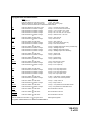
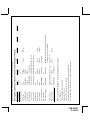
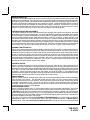
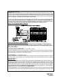
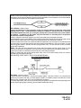
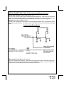
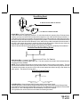
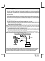
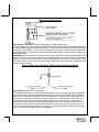
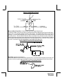
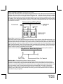
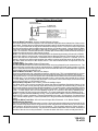
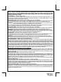
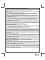
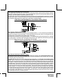
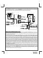
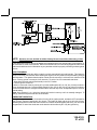
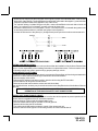
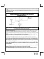
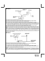
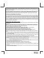
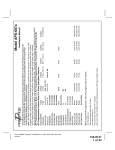
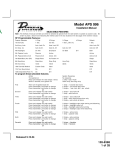
1
From APS997 with 07SP transmitters 5/07
128-8129
1 of 28
Passive
Passive Arm
Siren/Horn
10mS
Custom Code
On
On
Not Available
Not Available
Not Available
5th Passive Locks
6th Pass/Act Arm
7th Siren/Horn
8th Horn Chirp
9th O/R Method
10th 2 Step U/L
11th Chp Del Tx
12th Volts/HdWire
13th Trigger Circuits
14th L/UL Poll
Off
Off
Valet
16mS
Siren Only
Active Arm
Active
On Disarm
Auto UL All
Auto Lock Off
3.5 Sec.
2 Chirps
30mS
Horn Only
On Both
Auto UL Off
1 Sec L, Dbl. U/L
3 Chirps
Siren chirps 2 times indicating access to RF feature program mode.
Press and hold valet switch for 5 seconds
turn ignition off then on
Press and release valet switch 3 times
Turn the ignition on
When using the RF programmer, enter the program mode as follows:
Auto UL Dr.
On Arm
4th Headlights
2nd Accy Lock
3rd Accy. UL
1 Sec.
Auto Lock On
1st DoorL/UL
1 Chirp
Feature Selection
40mS
Off
Dbl L, 1 Sec UL
4 Chirps
50mS
Dbl L, Dbl UL
5 Chirps
1 S l/350mS ul
6 Chirps
RF Programmable Feature Bank 1 Is For Transmitter Programming See Transmitter Programming Guide.
RF Programmable Features Bank 2 Is Alarm Selectable Features:
Note : The method of manual override can either be selected to operate from the valet switch or operate as custom code.
Be certain to place a check mark indicating the method used in the box located on the last page of the owner's manual.
NOTE: Keyless Entry Models with no horn output will Flash the Parking Lights instead of chirp where chirp is indicated.
Also, No data will be indicated if a feature is not available for a particular model. The unit will enter the feature but no selection will be available.
SELECTABLE FEATURES
The selectable features can be set manually as explained below, or with the RF feature programmer.
To set features using the RF programmer, follow the instructions packaged with the programmer.
Factory default settings are indicated by bold text.
Installation Manual
Model APS-997a
To program these selectable features;
Action
System Response
Turn ignition on
No response
Press and release the valet switch 3 times
1 Chirp - LED 1 flash
Within 3 seconds, turn ignition Off Then On
Short chirp, then long chirp
This Action Accesses Feature Bank 2 Alarm Selectable Features
First
Press
Press
Press
Press
Press
Press
Second
Press
Press
Third
Press
Press
Press
Fourth
Press
Press
Press
Press
Fifth
Press
Press
Sixth
Press
Press
Seventh
Press
Press
Press
Eighth
Press
Press
Press
Press
Press
and release the valet switch 1 time
transmitter Lock button to change
transmitter Lock button to change
transmitter Lock button to change
transmitter Lock button to change
transmitter Lock button to change
or
and release the valet switch
transmitter Lock button to change
or
and release the valet switch
transmitter Lock button to change
transmitter Lock button to change
or
and release the valet switch
transmitter Lock button to change
transmitter Lock button to change
transmitter Lock button to change
or
and release the valet switch
transmitter Lock button to change
or
and release the valet switch
transmitter Lock button to change
or
and release the valet switch
transmitter Lock button to change
transmitter Lock button to change
or
1
2
3
4
5
6
chirp = 1 second door lock & unlock
chirps = 3.5 second door lock & Unlock
chirps = 1 sec. lock, dbl 1 sec. unlock
chirps = dbl 1 sec lock, 1 sec unlock
chirps = dbl 1 sec lock, dbl 1 sec unlock
chirps = 350mS unlock. 1 sec lock
2 chirps = auto locks off
1 chirp = auto locks on
3 chirps = auto unlock off
1 chirp = auto unlock drivers door only
2 chirps = auto unlock all doors
3
4
1
2
chirps = headlight output when arming and disarming
chirps = headlight output off
chirp = headlight output when arming
chirps = headlight output when disarming
2 chirps = active locks
1 chirp = passive locks
2 chirps = active arming
1 chirp = passive arming
1 chirp = siren and horn output
2 chirps = siren output only
3 chirps = horn output only
and release the valet switch
2 chirps = horn chirp output 16mS
transmitter Lock button to change
3 chirps = horn chirp output 30mS
transmitter Lock button to change
4 chirps = horn chirp output 40mS
transmitter Lock button to change
5 chirps = horn chirp output 50mS
transmitter Lock button to change
1 chirp = horn chirp output 10 mS
or
Ninth
Press and release the valet switch
2 chirps = valet switch override operation
Press transmitter Lock button to change
1 chirp = custom code override operation
or
Tenth
Press and release the valet switch
2 chirps = 2 step unlock off
Press transmitter Lock button to change
1 chirp = 2 step unlock on
or
Eleventh
Press and release the valet switch
2 chirps = chirp delete from transmitter inactive
Press transmitter Lock button to change
1 chirp = chirp delete from transmitter active
or
Twelfth
Press and release the valet switch
Non Functional On This Unit
or
Thirteenth
Press and release the valet switch
Non Functional On This Unit
or
Fourteenth
Press and release the valet switch
Non Functional On This Unit
or
Press and release the valet switch or turn the ignition off to:
Exit Programming Mode
or
Turn ignition switch off then on to advance to feature Bank 3:
2
128-8129
2 of 28
3
128-8129
3 of 28
Off
Single Pulse
17th Black/Blue (Aux O/P)
1.5 Sec
5 Mins
Shunt From Tx
10 Mins
4 times with the key to be effective.
To exit program mode, turn ignition off, or press and release valet switch.
Siren chirps 2 times indicating access to RF feature program mode.
Press and hold valet switch for 5 seconds
turn ignition off then on
Press and release valet switch 3 times
Turn the ignition on
Diesel 20
2.0 Sec
20 Mins
4 Chirps
5 Chirps
Note: When averaging, the engine must be started
Until Ign. Off
Diesel 15
When using the RF programmer, enter the program mode as follows:
As Feature #1
3 Mins
Shunt Until Clear Shunt R/S Cycle
Preset Time
On
During Start
16th Turbo Select
13th Temp Start
15th R/S Shock
Off
12th Transponder O/P
Diesel 10
1.0 Sec
On
On During Crank Same As Accy
Averaging
While R/S On
11th Gas/Diesel
15 Mins
3 Chirps
On During Crank Same As Accy.
< 0.5V B4 Start
Tach
Flashing
10 Mins
On
10 Mins
2 Chirps
14th Crank Averaging
0.8 Sec
Gas
10th Crank Time
Off During Crank
Off
Off During Crank
7th Ign. 2 Select
9th Diagnostics
>0.5V B4 Start
6th Voltage Level
8th Ign. 3 Select
On Steady
5 Mins
3rd Run Time
Voltage
Off
2nd RF Start Chirp
5th Input Check
Pulsed
1st Defrost Output
4th Parking Lights
1 Chirp
Feature Selection
RF Programmable Features Bank 3 Is Remote Start Selectable Features:
To exit program mode, turn ignition off, or press and release valet switch.
6 Chirps
Action
System Response
Turn ignition on
No response
Press and release the valet switch 3 times
1 Chirp - LED 1 flash
Within 3 seconds, turn ignition Off, On, Off, On
Short chirp, then 2 long chirps
This Action Accesses Feature Bank 3 Remote Start Selectable Features
First
Press the valet switch one time
Press transmitter Lock button to change
or
Second
Press and release the valet switch
Press transmitter Lock button to change
or
Third
Press and release the valet switch
Press transmitter Lock button to change
Press transmitter Lock button to change
Press transmitter Lock button to change
or
Fourth
Press and release the valet switch
Press transmitter Lock button to change
or
Fifth
Press and release the valet switch
Press transmitter Lock button to change
or
Sixth
Press and release the valet switch
Press transmitter Lock button to change
or
Seventh
Press and release the valet switch
Press transmitter Lock button to change
Press transmitter Lock button to change
or
Eighth
Press and release the valet switch
Press transmitter Lock button to change
Press transmitter Lock button to change
or
Ninth
Press and release the valet switch
Press transmitter Lock button to change
or
Tenth
Press and release the valet switch
Press transmitter Lock button to change
Press transmitter Lock button to change
Press transmitter Lock button to change
or
Eleventh
Press and release the valet switch
Press transmitter Lock button to change
Press transmitter Lock button to change
Press transmitter Lock button to change
or
Twelfth
Press and release the valet switch
Press transmitter Lock button to change
Press transmitter Lock button to change
or
Thirteenth
Press and release the valet switch
Press transmitter Lock button to change
or
Fourteenth
Press and release the valet switch
Press transmitter Lock button to change
or
Fifteenth
Press and release the valet switch
Press transmitter Lock button to change
Press transmitter Lock button to change
or
Sixteenth
Press and release the valet switch
Press transmitter Lock button to change
Press transmitter Lock button to change
Press transmitter Lock button to change
or
Seventeenth
Press and release the valet switch
Press transmitter Lock button to change
Press and release the valet switch or turn the ignition off to:
1 chirp = defrost output pulsed
2 chirps = defrost output 10 Mins
2 chirps = RF start chirp on
1 chirp = RF start chirp off
2
3
4
1
chirps = run time set for 10 mins
chirps = run time set fro 15 mins
chirps = run time set for 20 mins
chirp = run time set for 5 mins
1 chirp = parking lights on steady w/RS active
2 chirps = parking lights flashing w/RS active
2 chirps = tachometer input checking
1 chirp = voltage sense input checking
1 chirp = greater than 0.5 V check before start
2 chirps = less than 0.5 V check before start
2 chirps = ign 2 on during crank
3 chirps = ign 2 same as accessory
1 chirp = ign 2 off during crank
2 chirps = ign 3 on during crank
3 chirps = ign 3 same as accessory
1 chirp = ign 3 off during crank
1 chirp = diagnostics off
2 chirps = diagnostics on
2
3
4
1
chirps = crank time 1.0 sec
chirps = crank time 1.5 sec
chirps = crank time 2.0 sec
chirp = crank time 0.8 sec
1
2
3
4
chirp = unit set for gasoline engine
chirps = unit set for diesel engine 10 sec delay
chirps = unit set for diesel engine 15 sec delay
chirps = unit set for diesel engine 20 sec delay
1 chirp = transponder output while R/S active
2 chirps = transponder output during start only
3 chirps = transponder output until ignition turned off
1 chirp = temperature start off
2 chirps = temperature start on
1 chirp = crank averaging w/voltage input checking
2 chirps = preset crank time w/voltage input check
1 chirp = shk sensor shunted until clear
2 chirps = shk sensor shunted for the R/S Cycle
3 chirps = shk sensor shunted from tx 1 start cycle
1 chirp = turbo timer off
2 chirps = turbo timer 3 mins
3 chirps = turbo timer 5 mins
4 chirps = turbo timer 10 mins
1 chirp = aux o/p Black/Blue single pulse
2 chirps = aux o/p Black/Blue as alarm feature #1
Exit Programming Mode
Note : Once you enter the feature programming mode, do not allow more than 15 seconds to pass between steps or the
programming will be terminated.
4
128-8129
4 of 28
This Remote Start/Alarm System is designed to be used with Automatic Transmission- Fuel Injection
Vehicles Only! The unit provides a selectable ignition control that allows a number of selectable timed outputs
for glow plug preheat in addition to a "Wait To Start Input" either of which may be required for certain diesel
vehicles, (see selectable feature #11 Bank 3 & or Green/Yellow Wire). If the diesel engine has a instant fire, (no
glow plug preheat system), feature #11 of Bank 3 should remain in the default Gasoline mode setting. For
diesel applications, consult your dealer for the type of ignition system used in your particular vehicle.
Regardless of the vehicle, Gasoline or Diesel, for every installation, the vehicle MUST HAVE a Tach
Signal Input, Automatic Transmission and Fuel Injection.
INSTALLATION OF THE MAJOR COMPONENTS:
CONTROL MODULE:
Select a mounting location inside the passenger compartment (up behind the dashboard). The mounting
location selected must be within 24" of the ignition switch wiring harness to allow connection of the 6 pin
main wiring harness.
Be certain that the chosen location will not interfere with proper operation of the vehicle. Avoid mounting
the module to or routing the wiring around the steering shaft/column, as the module or wiring may wrap
around or block the steering wheel preventing proper control of the vehicle. Secure the module in the
chosen location using cable ties or screws as necessary.
Do Not Mount The Module In The Engine Compartment, as it is not waterproof.
SIREN:
Select a location in the engine compartment that is not accessible from below the vehicle. The selected
location must be clear of hot or moving parts within the engine compartment The siren must be pointed
downward to prevent water retention and the flared end must be pointed away from and out of the engine
compartment for maximum sound distribution. Before securing the siren, check behind your chosen
location to assure that the mounting screws will not penetrate any factory wiring or fluid lines. Secure the
siren mounting bracket using #8 self taping screws or by first using the mounting bracket as a template,
scribe or mark the mounting holes. Drill the marked holes using a 1/8" drill bit, then mount the siren using
#8 sheet metal screws.
HOOD AND TRUNK PIN SWITCHES:
The pin switches included in this package are intended for protecting the hood and trunk areas of the
vehicle. In all cases, the switch must be mounted to a grounded metal surface. When the pin switch is
activated, (hood/trunk open), it will supply a ground to the input wire activating the alarm. In addition, the
hood switch is required for the safety shut down of the remote start unit. If the vehicle is being worked on,
this hood switch prevents the remote start activation even if the RF command to start is issued. This
switch must be installed in all applications. Failure to do so may result in personal injury or
property damage. Mount the switches in the hood and trunk locations away from water drain paths. If
necessary, the included brackets may be used to move the switch away from rain gutters or allow
mounting to the firewall behind the hood seal. In both cases the switch must be set up to allow the hood
or trunk door to depress the switch at least 1/4 inch when the hood or trunk is closed and fully extended
when the hood or trunk is opened. For direct mounting, a 1/4 inch hole must be drilled. Carefully check
behind the chosen location to insure the drill will not penetrate any existing factory wiring or fluid lines.
Drill a 1/4" hole in the desired location and thread the pin switch into it using a 7/16" nut driver or deep well
socket. If using the mounting bracket, first secure the bracket to the desired location and secure the pin
switch in the pre-threaded mounting bracket hole.
5
128-8129
5 of 28
DASH MOUNTED LED:
The small LED included in the kit will serve as a visual indicator of the alarm's status and provide a visual
deterrent to a potential thief. The LED also provides important feed back information during the transmitter
and feature program modes. The LED should be installed in the dash in an area highly visible so that it may
be seen from the driver's seat as well as from outside the vehicle. Inspect behind the chosen location to
insure that the drill will not penetrate any existing factory wiring or fluid lines. Carefully drill a 1/4" hole in
the desired location and pass the connector end of the LED through the hole and toward the control
module. Press the LED firmly into place until it is fully seated in the mounting hole.
THE RECEIVER/ANTENNA ASSEMBLY:
The Superheterodyne Receiver Antenna Assembly provided with this unit allows routing from below the
dash board for maximum operating range. Choose a location above the belt line (dashboard) of the vehicle
for best reception. Special considerations must be made for windshield glass as some newer vehicles
utilize a metallic shielded window glass that will inhibit or restrict RF reception. In these vehicles, route
the antenna toward a rear window location for best reception. Secure the antenna with double stick tape
provided. After securing the antenna with tape, we advise also securing a section of the antenna cable to
a fixed support. This will prevent the antenna from dropping down in case the double stick tape is exposed
to extreme heat which may loosen it's gummed surface. Route the connector toward the control module
using caution not to pinch the cable as this will cause poor or no RF reception to the control module.
PUSHBUTTON LED SWITCH
Select a mounting location known and accessible to the operator of the vehicle. A dash knockout plug or
front dash panel is desirable as the now Push-Button LED assembly needs the LED to be visible from the
outside of the vehicle and will be used for valet modes, programming features, programming transmitters,
and for overriding the remote start unit when the vehicle is being serviced. Inspect behind the chosen
location to insure that adequate clearance is allowed for the body of the switch, and also that the drill will
not penetrate any existing factory wiring or fluid lines. Drill a 5/16" or 8mm hole in the desired location and
mount the switch by passing the connectors, one at a time, through the panel from the front side and
pressing on the bezel until the switch is fully seated.
CONTROL SWITCH:
Select a mounting location known and accessible to the operator of the vehicle. A lower dash panel, kick
panel, or glove box is desirable. Inspect behind the chosen location to insure that adequate clearance is
allowed for the body of the switch, and also that the drill will not penetrate any existing factory wiring or fluid
lines. Drill a 1/4" hole in the desired location and mount the switch by passing it through the panel from the
underside. Secure the switch using the nut, star washer, and on/off face plate. It is suggested that the
switch be oriented to allow the on position to be up toward the driver and the off position to be down or away
from the driver. Route the switch's connector toward the control module.
SHOCK SENSOR:
Select a centrally located, solid mounting surface for the shock sensor that will allow consistent operation
from all areas of the vehicle. The selected location must be within 18" of the control module to allow
routing and connecting of the 4 pin harness. Secure the shock sensor to the chosen location using two #8
self tapping sheet metal screws. The sensor can also be secured to an existing dash brace using cable
tie straps. Whichever mounting method is used be sure to allow access to the sensitivity adjustment
potentiometer for use later in the installation.
STARTER INHIBIT RELAY:
Select a mounting location within 12" of the ignition switch's low current start solenoid wire. Secure the
relay to an existing harness in the chosen location using a cable tie around the relay's wiring harness.
CAUTION! Do not wire tie the metal bracket to an existing wiring harness as vibration may cause chaffing
and shorting damaging the factory wiring. If an existing harness is not available then secure the relay's
metal mounting tab to an under dash metal brace with a #8 self tapping sheet metal screw. Wire the relay
as per the diagram found later in this manual.
This unit is to be used in vehicles with AUTOMATIC TRANSMISSIONS only! Although this combination
Alarm/Remote Start unit is a sophisticated system with many advanced features, IT MUST NOT be
installed into a vehicle with a manually operated transmission. Doing so may result in serious personal
6
128-8129
6 of 28
injury and property damage.
IMPORTANT! It is the responsibility of the installing technician to determine the load factor of the vehicles
electrical circuits when the vehicle is running, and to adequately fuse the three power wires based on that
load. If the vehicle, running under load with the air conditioner, heater blower motor, and accessories exceed
24 Amps continuous, we recommend that two fuses be used in combination on each power wire as shown
below. For additional information see Tech Update issued 9/30/96.
DO NOT PLUG THE SIX PIN MAIN POWER HARNESS OR THE MULTI PIN INPUT / OUTPUT HARNESS
INTO THE CONTROL MODULE UNTIL ALL CONNECTIONS TO THE VEHICLE HAVE BEEN MADE. AFTER SELECTING YOUR TARGET WIRES AS DEFINED BELOW, DISCONNECT THE NEGATIVE BATTERY CABLE FROM THE VEHICLE BATTERY PRIOR TO MAKING ANY CONNECTIONS.
WIRING THE 6 PIN MAIN POWER HARNESS:
WIRING THE 6 PIN MAIN POWER HARNESS:
Note: Do not remove the fuse holders from this wire harness. Fuses must be
used and located as close as possible to the power source for adequate protection of the vehicle.
Fused RED w/ WHITE TRACE WIRE: + 12 volt Battery 1 Source
Locate the vehicle battery wire(s) at the ignition switch. Verification: These wires will register voltage in all positions
of the ignition switch. Connect the Red w/White wire to the vehicle's battery wire. This wire provides power for the
control circuit as well as the ignition 1 and ignition 2 relays.
Fused RED WIRE: + 12 Volt Battery 2 Source
Locate the vehicle battery wire(s) at the ignition switch. Verification: These wires will register voltage in all positions
of the ignition switch. Connect the Red wire to the vehicle's battery wire. This wire provides power for the start relay
and the accessory relay.
I M P O R TA N T !
IT IS THE RESPONSIBILITY OF THE INSTALLING TECHNICIAN TO DETERMINE THE LOAD FACTOR OF THE
VEHICLES ELECTRICAL CIRCUITS WHEN THE VEHICLE IS RUNNING AND TO ADEQUATELY FUSE THE TWO
POWER WIRES BASED ON THAT LOAD. IF THE VEHICLE, RUNNING UNDER LOAD WITH THE AIR CONDITIONER, HEATER BLOWER MOTOR, AND ACCESSORIES EXCEEDS 24 AMPS CONTINUOUS, WE RECOMMEND
THAT TWO FUSES BE USED IN COMBINATION ON EACH POWER WIRE AS SHOWN BELOW. FOR ADDITIONAL
INFORMATION SEE TECH UPDATE ISSUED 9/30/96.IMPORTANT!
It is the responsibility of the installing technician to determine the load factor of the vehicles electrical
circuits when the vehicle is running, and to adequately fuse the two power wires based on that load. If the
7
128-8129
7 of 28
vehicle, running under load with the air conditioner, heater blower motor, and accessories exceed 24 Amps
continuous, we recommend that two fuses be used in combination on each power wire as shown below.
For additional information see Tech Update issued 9/30/96.
YELLOW Wire: Starter Output
Careful consideration for the connection of this wire must be made to prevent the vehicle from
starting while in gear. Understanding the difference between a mechanical and an electrical
Neutral Start Switch will allow you to properly identify the circuit and select the correct installation method. In addition you will realize why the connection of the safety wire is required for
all mechanical switch configurations.
Failure to make this connection properly can result in personal injury and property damage.
In all installations it is the responsibility of the installing technician to test the remote start unit and ensure
that the vehicle cannot start via RF control in any gear selection other than park or neutral.
In both mechanical and electrical neutral start switch configurations, the connection of the Yellow wire will
be made to the low current start solenoid wire of the ignition switch harness. This wire will have +12 volts
when the ignition switch is turned to the start (crank) position only. This wire will have 0 volts in all other
ignition switch positions.
NOTE: This wire must be connected to the vehicle side of the starter cut relay (when used). For the
electrical neutral switch configuration, this connection must be made between the starter inhibit relay,
( when used ) and the neutral safety switch as shown in the following diagram.
Failure to connect this wire to the ignition switch side of the of the neutral safety switch can result in
personal injury and property damage.
SEE NEUTRAL START SAFETY TEST FOR FURTHER DETAILS.
YELLOW START WIRE DETAIL
BLUE Wire: Ignition 1 Output
Connect this wire to the ignition 1 wire from the ignition switch. This wire will show +12 volts when the
ignition key is turned to the "ON" or "RUN" and the "START" or CRANK" positions, and will have 0 volts
when the key is turned to the "OFF" and "ACCESSORY" positions.
For Diesel Applications, this wire must be connected to the ignition circuit that powers the glow plugs if the
vehicle requires glow plug pre-heating. (See selectable feature Bank 3 #11)
8
128-8129
8 of 28
GREEN Wire: Ignition 2 Output
Connect this wire to the ignition 2 wire from the ignition switch. This wire will show + 12 volts when the
ignition key is turned to the "ON" or "RUN" position and is some cases the "START" or CRANK" position.
This wire will show 0 volts when the key is turned to the "OFF" and "ACCESSORY" positions.
NOTE: See programming information (Bank 3 Selection #2) concerning this wire to allow output during the
"START" mode.
VIOLET Wire: Accessory Output
Connect this wire to the Accessory wire from the ignition switch. This wire will show + 12 volts when the
ignition switch is turned to the "ACCESSORY" or "ON" and "RUN" positions, and will show 0 volts when
the key is turned to the "OFF" and "START" or "CRANK" positions.
WIRING THE 4 PIN ALTERNATE IGNITION HARNESS
ORANGE/BLACK Wire: Parking Brake Input
This wire is used only when the turbo timer mode, Bank 3, feature # 16 is selected ON. This input insures
that the vehicle parking brake is applied whenever the vehicle is set up for and the turbo timer circuit is used.
This input must switch to ground when the vehicle's parking brake is applied. Connect the Orange/Black wire
to the negative output of the vehicle's parking brake switch.
RED/BLACK Wire: + 12 Volts Input
Note: The Red/Black and Pink are dry contacts and may be used for negative switching when necessary.
Connecting the Red/Black to chassis ground will result in Pink being ground when the R/S is activated.
This input is to be connected to a separate, (Other than the wire Red or Red/White is connected to), constant
on + 12 volt source which will supply + 12 volt power to the additional ignition output, (Pink), wire. Connect
this wire to a separate + 12 Volt source.
PINK Wire: Additional Ignition Output
This wire can be used as an additional + 12 Volt ignition output supplied by the Red/Black wire. This output
can be selected to be on or off during the start cycle. (See feature bank 3 selection # 8) Connect this wire
to the third ignition circuit in the vehicle and set the selectable feature # 8 of Bank 3 according to the way
in which the vehicle's ignition switch operates.
Note: Do not remove the fuse holders from this wire harness. Fuses must be
used and located as close as possible to the power source for adequate protection of the vehicle.
9
128-8129
9 of 28
WIRING CONNECTIONS: Multi Pin Accessory Input/Output Harness
White w/ Red Trace Wire: Parking Light Flasher Feed
This wire is the common contact of the on board parking light flasher relay. If the vehicle you are working
on has +12 volt switched parking lights, connect this wire to a fused + 12 volt source. (Max. 15 Amps)
NOTE: If the vehicle's parking lights are ground switched, connect this wire to chassis ground.
White Wire: Parking Light Flasher Output
This wire is the normally open contact of the on board parking light flasher relay. Connect this wire to the
vehicle parking light feed wire. See diagram below for details on wiring positive switched parking light
circuits.
Parking Light Wiring Detail
White w/ Black Trace Wire: (+) Siren Output
This is the positive siren feed wire. Route this wire through a grommet in the firewall to the siren
location. Connect the White w/ Black Trace wire to the Red wire of the Siren. Secure the Black wire
of the Siren to a known chassis ground or solid clean metal surface.
10
128-8129
10 of 28
Siren Wiring Detail
TO WHITE w/BLACK WIRE OF MODULE
(-) TO VEHICLE'S CHASSIS GROUND
Purple Wire: (+) Door Trigger Input
If the vehicle's door courtesy light switches + 12 volts when the door is opened, (Some Fords and some
Imports), you must connect this wire to the positive output from one of the vehicle's door pin switches. In
most cases, the Purple wire will need to be connected to only one door switch no matter how many doors
the vehicle has as most door lighting circuits are wired in parallel. This wire will be shunted when remote
starting the vehicle and will remain shunted, if active, while running under command of the remote start. If
this wire is active when the system is armed, the siren will emit three chirps. When the zone clears, the
siren will emit 1 chirp to confirm full arming. See below for wiring details.
Note for vehicles with interior delay lighting see programming under title "Completing The Installation".
Positive Door Switch Wiring Detail
Dark Green Wire: (-) Instant Trigger Input
This is the instant on ground trigger input wire. This wire must be connected to the hood and trunk pin
switches previously installed.
NOTE: This wire will be shunted when remote control channel 3 is accessed, (trunk release). This wire
will remain shunted all the while there is ground present and for 5 seconds after the ground is removed.
This allows the operator to open the trunk via the remote transmitter without having to first disarm the
alarm system. See below for wiring detail.
Hood Pin Switch Detail
Light Blue Wire: Ground Output While Running Under Remote Start Control
This wire provides a 300mA ground output that becomes active 3 seconds before the Remote Start
Unit initializes and remains grounded while running plus an additional 4 seconds after the Remote Start
Unit turns off. In all of the applications described below, a relay will be required.
The Light Blue wire can be used to accommodate the following situations:
11
128-8129
11 of 28
A. Shock Sensor By Pass:
If there is a Non Plug in Shock Sensor used with the alarm system and it is not shunted during the
Remote Start activation period, then vibration from the running vehicle can cause the alarm to trigger. In
this case, connect the Light Blue Wire to terminal #86 of a external relay. Connect terminal # 85 of the
relay to a fused + 12 volt battery source. Cut the shock sensor trigger wire and connect one end of the
cut wire to terminal #30 and the other end of the cut wire to terminal #87a. Just before the Remote Start
unit is activated, the relay contacts will open, preventing the shock sensor's operation until the Remote
Start unit shuts off.
B. Additional Ignition Output:
Some newer vehicles more than three ignition outputs to start and keep the vehicle's engine running. If
this is the case, connect the Light Blue wire to terminal #86 of an external relay. Connect terminal # 30
& # 85 to a fused + 12 volt battery source rated for a minimum of 25 Amp. Connect terminal # 87 to the
third ignition wire in the vehicle.
C. GM VATS Key Override:
If the vehicle has the General Motors VATS system installed, you will need to bypass the system while
the vehicle is operating under the control of the Remote Start Unit. To Do This:
1. Measure the resistance of the resistor pellet on the ignition key then select a resistor within 5% of the
key's value from the resistor pack supplied.
2. Locate the pair of VATS wires in the vehicle, usually a pair of thin gauge wires running from the
ignition switch to the VATS control module.
NOTE: These wires are typically White w/ Black trace and Violet w/ Yellow trace, however in later model
Cadillacs, they are run through an orange sleeve, and are either both Black, both Yellow, or both White
wires. Consult the factory service manual for additional information.
3. Connect the Light Blue Wire from the Remote Start Unit to terminal #86 of an external relay. Connect
terminal #85 of the relay to a fused + 12 volt battery source.
4. Cut (#1) wire (as shown), and connect the ignition switch side of the cut wire to terminal #87a of the
relay. Connect the other side of the (#1) wire to terminal #30.
5. Connect the previously selected resistor from terminal #87 to the second (#2) wire (as shown).
NOTE: The above information and following diagram is for the GM VATS system only. For GM PASS
LOCK System you will require the Audiovox AS-PASS II Module.
General Motors VATS By-Pass Diagram
Green w/ White trace Wire: Entry Illumination Ground Output
This wire provides a 30 second ground output (300 mA Max.) whenever the remote is used to disarm the
alarm or to unlock the doors and provides a continuous pulsed output whenever the alarm is triggered.
This wire should be connected to an external relay and wired to the vehicles interior entry lighting
whenever the optional Interior Illumination circuit is desired. See below for relay wiring details.
12
128-8129
12 of 28
Entry Illumination Detail
Grey w/ Black Trace Wire: Negative Inhibit Input Plus Trigger When Armed
The Grey w/ Black Trace wire provides an instant shutdown for the Remote Start Control Module whenever
it is grounded also trigger for the alarm when armed. Connect the Grey w/ Black trace wire to the hood pin
switch previously installed. This wire must be routed through a grommet in the firewall and connected to
the hood pin switch. If the pin switch is to be used with an alarm system, connect this wire using the diode
assembly provided.
IMPORTANT! This connection is a safety wire and must be connected as shown and tested as specified.
Failure to do so may result in personal injury or property damage. See detail of wiring in the following
diagram. This wire may also be used if the vehicle brake light circuit switches ground to the brake lights.
An isolation diode must be used for ground switched brake light circuits and must be connected to the
output of the brake switch.
Grey w/ Black Trace Negative Inhibit Safety Shut Down Detail
Orange Wire: Ground When Armed Output
This wire provides a 300 mA ground output when the alarm circuit is armed to control the starter inhibit
relay. Connect the Orange wire to terminal #86 (orange wire) of the relay provided. Connect terminal
#85 (red wire) of the relay to an ignition wire in the vehicle that is +12 volts when the ignition switch is
turned to the on and start positions and off when the key is off. Locate and cut the low current start
solenoid wire found at the vehicles ignition switch harness. This wire will have + 12 volts when the
ignition key is moved to the start (crank) position and will have 0 volts in all other key positions. Connect one side of the cut wire to terminal #87a ( Black wire) of the relay. Connect the other side of the
cut wire to terminal #30 (White/Black wire) of the relay. See below for detail of wiring, also see Yellow
Start wire detail for connection to vehicle considerations.
13
128-8129
13 of 28
Starter Inhibit Wiring Detail
Black
White/Black
Brown w/ Black Trace Wire: Positive Inhibit Input Plus Trigger When Armed
The Brown w/ Black Trace wire provides an instant shutdown for the Remote Start Control module whenever it gets + 12 volts also triggers the alarm when armed. If the Brake lights switch in the vehicle
switches + 12 volts to the brake light circuit, connect the Brown w/ Black trace wire to the output side of
the brake switch. This will allow the Remote Start to shut down if an attempt is made to operate the
vehicle without the key while running under the control of the Remote Start. In most vehicles, in order to
shift into gear, the brake pedal must be depressed. The brake input will in turn cause the remote start unit
to shut off. See detail in the following diagram for wiring the brake light circuit.
Brake Switch Positive Shutdown Detail
Black Wire: Chassis Ground Source
Connect the Black wire to a known vehicle ground source or to a solid clean metal part of the chassis. Be
certain to remove any paint or grease and secure this wire with a self tapping screw and ring terminal.
Chassis Ground Connection Detail
14
128-8129
14 of 28
Green w/ Orange Trace Wire: Tachometer Input Signal
This wire will continually monitor the engine's tach rate while the unit is under power of the Remote Start
module. This wire will be routed to the vehicle ECM tach input or through the firewall into the engine
compartment and connect to the negative side of the ignition coil. This Remote Start unit learns the tach
rate of the vehicle and in most cases will operate properly from one multi coil pack regardless of the number
of cylinders. If the vehicle has a single coil unit for each cylinder, it may be necessary to connect this wire
to more than one cylinder for proper tach reference. See multi coil wiring detail shown later in this manual
for additional information.
Tachometer Input Wiring Detail
Brown Wire: Negative Door Trigger
If the vehicle's door courtesy light switches ground when the door is opened, (Most GMs and Imports), you
must connect this wire to the negative output from one of the vehicle's door pin switches. In most cases the
Brown wire will need to be connected to only one door switch no matter how many doors the vehicle has as
most door lighting circuits are wired in parallel. This wire will be shunted when remote starting the vehicle
and will remain shunted, if active, while running under command of the remote start. If this wire is active
when the system is armed, the siren will emit three chirps. When the zone clears, the siren will emit 1
chirp to confirm full arming. See below for wiring detail.
Note for vehicles with interior delay lighting see programming under title "Completing The Installation".
Negative Door Switch Wiring Detail
Dark Blue Wire: Delayed 300mA Pulsed Channel 3 Output
The Dark Blue wire supplies a 300mA ground pulsed output whenever channel three of the receiver is
accessed. Pressing the pre-programmed transmitter button for three seconds will access channel two.
This is a low current output and must be connected to a relay to supply power to the trunk release or the
circuit you wish to control. Connect the Dark Blue wire to terminal # 86 of a VF45F11 P&B relay or
equivalent. Connect terminal # 85 of the relay to a fused + 12 volt source. Connect the common,
normally open, and normally closed contacts of the relay to perform the selected function of channel 3.
See below for relay wiring detail.
15
128-8129
15 of 28
Channel 3 Relay Wiring Detail
Green w/ Black Trace Wire: 300mA Latched Channel 4 Output
The Green w/ Black Trace wire supplies a 300 mA switched output whenever channel four of the receiver
is accessed. Pressing the pre-programmed transmitter button(s) will access channel four and will remain
active, for up to 20 seconds, as long as the transmitter button(s) is held. This is a low current output and
must be connected to a relay to supply power to the device you intend to control. Connect Green w/ Black
Trace wire to terminal #86 of a VF45F11 P&B relay or equivalent. Connect terminal #85 of the relay to a
fused + 12 volt source. Connect the common, normally open, and normally closed contacts of the relay to
perform the selected function of the channel 4 output.
NOTE: This wire also can be used for defrost activation as dictated by the setting of feature # 1 of Bank 3.
Anytime the vehicle is running under control of the Remote Start and Channel 4 is activated, then dependent on the selection of this feature, Green/Black will be activated as a pulse for 1 second, or for 10
minutes. Note this wire will not operate when the vehicle is running under the power of the ignition key,
only while under the control of the remote start or if not used for defrost then an output will occur as
indicated above.
Dark Blue/Black Trace Wire: External Trigger Input
The Dark Blue/Black trace wire allows the remote start unit to be activated from an external source. The
intent of this wire is to allow the unit to be controlled from a "POSSE/CAR-LINK" paging system or similar
device. When this wire receives a ground pulse, the unit will start the vehicle. Connect this wire to a ground
pulsed output from the controlling circuit.
Black w/ White Trace Wire : 300 mA Horn Output
The black w/ white trace wire is provided to beep the vehicle’s horn. This is a transistorized low current
output, and should only be connected to the low current ground output from the vehicle’s horn switch.
If the vehicle uses a + 12 VDC horn switch, then connect the black w/ white trace wire to terminal 86 of the
AS 9256 relay ( or an equivalent 30 Amp automotive relay ), and connect relay terminal 85 to a fused
+ 12 VDC battery source. Connect relay terminal 87 to the vehicle’s horn switch output, and connect relay
terminal 30 to a fused + 12 VDC battery source.
White w/ Blue Trace Wire: Low Current (-) Ground Headlight Output
The White w/ Blue Trace wire is provided to operate the optional headlamp illumination feature of the
system. This is a low current (300mA) output and must be connected to an external relay to control the
high current switching circuit of the vehicle's headlamps. To use this option, connect the White /w Blue
Trace wire to terminal # 86 of a P&B VF45F11 relay or equivalent. Connect Terminals #85 and # 30 to a
fused + 12 Volts source with a current capability equal to or in excess of the factory headlamp fuse.
Connect terminal # 87 of the relay to the switched + 12 volt wire feeding the vehicle's headlamp circuit.
NOTE: For ground switched headlamp circuits, Connect the White /w Blue Trace wire to terminal # 86 of
a P&B VF45F11 relay or equivalent. Connect Terminal #85 to a fused + 12 Volts source. Connect terminal
# 30 to a clean chassis ground. Connect terminal # 87 to the ground switched headlamp control wire in the
vehicle.
Orange w/ White Trace Wire : 300 mA Ground Output When Disarmed - N. O. Starter Disable
(Optional Relay Required).
This wire is provided to control the starter cut relay. Connect the orange w/white wire to terminal 86 of the
relay. Connect relay terminal 85 to an ignition wire in the vehicle that is live when the key is in the on and
crank positions, and off when the key is in the off position. ( This is typically where the yellow, (ignition),
wire of an alarm would be connected ). Cut the low current starter solenoid wire in the vehicle, and connect
one side of the cut wire to relay terminal 87. Connect the other side of the cut wire to relay terminal 30.
16
128-8129
16 of 28
NOTE : This is a normally opened starter cut arrangement, when power is removed from the
security system, the starter disable feature will remain operational, and the vehicle will not start.
Audiovox does not recommend using the Orange w/ White trace wire to interrupt anything but the
starting circuit of the vehicle.
Lt Green Wire: (-) Instant Trigger Zone 1
This is a instant on ground trigger input intended for the connection of optional triggering devices. The
ground trigger output wire of motion detectors, microwave detectors, or glass break detectors, can be
connected to this Light Green trigger input wire.
Lt Blue/Green Wire : DELAYED 300 mA PULSED OUTPUT / CHANNEL 5
The light blue/green wire pulses to ground via an independent RF channel from the keychain transmitter.
This is a transistorized, low current output, and should only be used to drive an external relay coil.
WARNING: Connecting the light blue/green to the high current switched output of trunk release circuits,
some remote start trigger inputs, will damage the control module.
Connect the light blue/green to terminal 86 of the AS - 9256 relay (or equivalent 30 A automotive relay) and
wire the remaining relay contacts to perform the selected function of channel 5.
Lt Blue/Black Wire : DELAYED 300 mA PULSED OUTPUT / CHANNEL 6
The light blue/green wire pulses to ground via an independent RF channel from the keychain transmitter.
This is a transistorized, low current output, and should only be used to drive an external relay coil.
WARNING: Connecting the light blue/black to the high current circuits, will damage the control module.
Connect the light blue/black to terminal 86 of the AS - 9256 relay (or equivalent 30 A automotive relay) and
wire the remaining relay contacts to perform the selected function of channel 6.
Blue/Red Wire : DELAYED 300 mA PULSED OUTPUT / CHANNEL 7
The light blue/red wire pulses to ground via an independent RF channel from the keychain transmitter. This
is a transistorized, low current output, and should only be used to drive an external relay coil.
WARNING: Connecting the light blue/red to the high current circuits, will damage the control module.
Connect the light blue/red to terminal 86 of the AS - 9256 relay (or equivalent 30 A automotive relay) and wire
the remaining relay contacts to perform the selected function of channel 7.
Green/Yellow Wire: DIESEL WAIT TO START INPUT
The green/yellow wire, when connected to the wire that get + 12 volts during the glow plug preheat stage will
delay the starter output until this wire drops the 12 volts. In other words, in a Diesel vehicle with glow plug
preheat circuit, when the ignition is turned on, the vehicle will not crank until the glow plugs are hot enough
to fire the atomized fuel oil when injected into the cylinder. By connecting this wire to the glow plug + 12 volt
wire, when the remote start unit activates the ignition one output, the glow plug output also activates. The
remote start sees the green/yellow with positive voltage and waits for this to go inactive( drop the 12 volts)
before activating the starter motor. If this wire is not used or you have difficulty accessing the glow plug
preheat circuit, you may elect to utilize the Diesel timed output as specified in Remote Start feature selection #9. NOTE: If green/yellow is used, it will override or negate any setting of feature #9.
WIRING THE 4 PIN AUXILIARY OUTPUT HARNESS
The auxiliary 4 pin connector provides low current outputs to control various functions in the vehicle during
different stages of the Remote Start unit's operation. Understanding these outputs and the time in which
they occur will allow you to determine if they are needed for the particular vehicle you are working on as well
as how to use them.
Black w Blue Trace Wire: Pulsed Ground Output Before Start
The Black w/ Blue Trace wire will provide a 1 second 300 mA pulsed ground output 1.5 second before the
remote start unit activates as well as when the transmitter is used to disarm the system. Typical use for
this output would be to disarm a factory theft deterrent system to prevent false triggering of the factory alarm
when the remote start unit engages or when the system is used to unlock the doors.
NOTE: This output can be selected to operate like the door lock output as set in alarm feature setting #1 by
selecting feature #7 on.
Black w/ Light Green Trace Wire: Pulsed Ground Output After Start
The Black w/ Light Green Trace wire will provide a 1 second 300mA pulsed ground output after the vehicle
is started under control of the remote start unit. Typically this wire will be used to re-lock the vehicle doors
if the doors unlock automatically when the factory anti-theft system is disarmed. This wire will also activate
when the transmitter is used to alm/lock the system.
Black w/ Red Trace Wire: Pulsed Ground Output After Shutdown
The Black w/ Red Trace wire will provide a 1 second 300 mA pulsed ground output after the remote start unit
shuts down. This output will occur regardless of whether the circuit times out or is manually terminated.
Typically this output will be used to re-lock the vehicle doors if the doors unlock automatically when the
ignition circuit transitions to off.
17
128-8129
17 of 28
Black w/ Yellow Trace Wire: Ground Output During Start (Crank)
The Black w/ Yellow Trace wire will provide a 300 mA ground output while the starter output of the remote
start unit is active. This output can be used to activate the Crank Low/Bulb Test wire found in some GM
vehicles. This wire is also referred to as the ECM wake up wire in some vehicles.
NOTE: The outputs above are low current outputs and must be used with a relay if the circuit's requirement
is more than 300 mA.
2 Pin Transponder Control Output: (Yellow Connector)
This output is intended to allow the control of a transponder bypass interface module or transponder
bypass relay. The system also allows software selections to control the way in which this output
operates, see remote start feature # 10 for setting this output.
When the unit is selected for output during the start sequence, this output will be active at the same
time Ign. 3 becomes active, and will remain active until the vehicle has started. This will be used for one
time read transponder circuits.
When the unit is selected for transponder on, this output will become active at the same time ign. 3
becomes active, and will remain active all the time the unit is operational under the control of the remote
start. When the unit is selected for continuous and the vehicle is started via the Remote Start, this
output will become active at the same time ign. 3 becomes active and will remain active until the ignition
in the vehicle goes low. This will allow the unit to be used for continuous read transponders circuits.
2 Pin Control Switch: (Red Connector)
The Black & Black w/White Trace wires loaded in the two pin red connector enable the operation of the
Remote Start unit. When the Black w/ White Trace wire is grounded, the remote start unit is operable.
When this wire is open from ground, the remote start is disabled. Route the twin lead Black & Black w/
White Trace wires from the control switch to the remote start unit and plug red two pin connector into the
mating red two pin connector shell of the control module.
4 Pin Upgrade Telematic Module:
Red = + 5 Volts / Black = Ground / White = Data TX / Yellow = Data RX
Connect the 4 pin harness found in the Telematic one way module kit to the mating port on the controlling circuit.
NOTE: If using the TWO WAY Telematic module, only Ground, TX, and RX are used on this port, the + 12 volt supply
for the two way module must be sourced separately or the unit will not operate.
2 Pin Valet/Program/Override Push-Button Switch: (Blue Connector)
The Black & Grey twin lead wires loaded in the two pin blue connector are the ground supply and program/
valet/override input of the Remote Start unit. When the Grey wire is grounded, under certain conditions, the
unit will enter the valet mode. When the Grey wire is sequentially grounded under other conditions, the unit
will enter the various program modes. Route the twin lead Black and Grey wires from the valet/Program
switch to the remote start unit and plug the two pin connector into the mating blue connector shell of the
control module. Refer to the remote programming, feature programming and function programming shown
later in this installation guide for operation of the valet/program switch. For override information, refer to the
owners manual.
4 Pin Antenna/Receiver Connector:
Plug the previously routed connector from the antenna receiver assemble into the mating connector of the
control module. This connector supplies 12 volts, ground and RF data from the antenna receiver to the
remote start module. Be certain this connector is firmly seated making good contact to the control unit.
4 Pin Shock Sensor: (White Connector)
The Red (+12 volt), Black (ground), Blue (pre-detect) and Green (full trigger when armed) wires loaded into
the white connector shell are the inputs/outputs of the shock sensor. Route the 4 wire harness from the
shock sensor to the remote start control unit and plug the 4 pin white connector into the mating 4 pin
connector shell of the control module.
NOTE: While operating under the control of the remote start unit the shock sensor will be shunted (bypassed). Once the remote start shuts down, the shock sensor will be re-enabled.
2 Pin LED Harness: (White Connector)
The Red & Blue wires loaded into the two pin mini white connector control the anode and cathode of the
dash mounted LED. Route the twin lead Red and Blue wires from the LED to the remote start control unit
and plug the two pin connector into the mating white mini connector shell of the control module.
3 Pin Door Lock/Unlock Harness: (White Connector)
The Red and Green wires will provide either a pulsed ground output to the factory door lock control relay, or
a pulsed + 12 volt output to the factory door lock control relay. In either case, the maximum current draw
through these outputs must not exceed 300 mA. The Red w/Black trace wire will provide a pulsed ground
only, and will only provide an output when the unlock button of the transmitter is pressed a second time
after a first unlock command was issued. This is used for second step unlock or all doors unlock in a two
step circuit. In this arrangement, Red is used to control the drivers door unlock relay, and the Red/Black
will be used to control unlock of all other doors.
18
128-8129
18 of 28
3 Wire Ground Switched Door Lock Circuits:
In this application, the Red wire of the door lock harness provides a ground pulse during the arming
sequence, or pulsed ground lock output. Connect the Red wire to the low current ground signal wire from
the factory door lock switch to the factory door lock relay.
The Green wire of the door lock harness provides a ground pulse during the disarming sequence, or pulsed
ground unlock output. Connect the Green wire to the low current ground signal wire from the factory door
unlock switch to the factory door unlock relay. See Below For Wiring Detail.
3 WireGround Switched Door Lock/Unlock Wiring Detail
3 Wire Positive Switched Door Locks:
In this application, the Red wire of the door lock harness provides a + 12 volt pulse during the disarming
sequence, or pulsed 12 volt unlock output. Connect the Red wire to the low current 12 volt signal wire from
the factory door unlock switch to the factory door unlock relay.
The Green wire of the door lock harness provides a + 12 volt pulse during the arming sequence, or pulsed
12 volt lock output. Connect the Green wire to the low current 12 volt signal wire from the factory door lock
switch to the factory door lock relay. See Below For Wiring Detail.
3 Wire Positive Switched Door Lock/Unlock Wiring Detail
3 Wire Ground Switched 2 Step Door Locks:
In this application, the red wire provides a ground pulse during arming, or the pulsed ground lock output.
Connect the red wire to the wire that provides a low current ground signal from the factory door lock switch
to the factory door lock control relay.
The green wire provides the first ground pulse during disarming, or the drivers door pulsed ground
unlock output. Connect this wire to the drivers door unlock relay that requires a low current ground
signal to unlock only the drivers door. If the vehicle does not have a separate drivers door relay, one will have
to be added. Locate the drivers door unlock motor wire and cut it at a convenient location to allow wiring of
an optional relay. Connect the door side of the cut wire to terminal 30 of the optional relay added. Connect
the vehicle side of the cut wire to terminal 87a of the optional relay added. Connect the green wire of the 3
pin harness to terminal 86 of the optional relay added. Connect terminal 85 of the optional relay added to
a fused constant + 12 volt source. Most vehicles door lock/unlock motor legs rest at ground, and switch
+12 volts to the door lock/unlock motor legs for operation, if this is the case in the vehicle you are working
on, connect the remaining terminal, 87, to a fused + 12 volt source. In the rare instance that the vehicle
door lock/unlock motor legs rest at + 12 volts and switches ground to the door lock/unlock motors, connect
the remaining terminal, 87, to chassis ground.
19
128-8129
19 of 28
The Red/Black wire provides a pulse ground output when the unlock button of the transmitter is pressed a
second time after disarming. Connect the Red/Black wire to the wire that provides a low current ground
signal from the factory door unlock switch to the factory door unlock control relay.
3 Wire Positive Switched 2 Step Door Locks:
The green wire provides a positive pulse during arming or the pulsed + 12 volt lock output. Connect the
green wire to the wire that provides a low current positive signal from the factory door lock switch to the
factory door lock control relay.
The red wire provides a positive pulse during disarming or the drivers door pulsed positive unlock
output. Connect this wire to the drivers door unlock relay that requires a low current positive signal to
unlock only the drivers door. If the vehicle does not have a separate drivers door relay, one will have to be
added. Locate the drivers door unlock motor wire and cut it at a convenient location to allow wiring of an
optional relay. Connect the door side of the cut wire to terminal 30 of the optional relay added. Connect the
vehicle side of the cut wire to terminal 87a of the optional relay added. Connect the red wire of the 3 pin
harness to terminal 86 of the optional relay added. Connect terminal 85 of the optional relay added to
chassis ground. Most vehicles door lock/unlock motor legs rest at ground, and switch +12 volts to the door
lock/unlock motor legs for operation, if this is the case in the vehicle you are working on, connect the
remaining terminal, 87, to a fused + 12 volt source. In the rare instance that the vehicle door lock/unlock
motor legs rest at + 12 volts and switches ground to the door lock/unlock motors, connect he remaining
terminal, 87, to chassis ground.
The Red/Black wire provides a pulse ground output when the unlock button of the transmitter is pressed a
second time after disarming. Because the vehicle you are working on requires a positive pulse from the
factory door lock switch to the factory door lock control relay, you will have to add a relay to invert the output
polarity of this wire. Connect the Red/Black wire to terminal 86 of the optional added relay. Connect
terminal 85 & 87 to a fuse + 12 volt source. Connect terminal 30 to the low current door unlock wire from the
factory door switch to the door unlock control relay.
20
128-8129
20 of 28
NOTE: Resistive Circuits, As Well As 4 Wire Polarity Reversal and 5 Wire Alternating 12 Volt
Door Lock Control Circuits
These applications require the use of additional components which may include relays, fixed resistors, or
for convenience, a Door Lock Interface. Refer to the AUDIOVOX Door Lock Wiring Supplement and or the
Audiovox fax back service for information on your particular vehicle for properly connecting to these types of
circuits.
START PROGRAM:
The Remote Start unit has the ability to start the vehicle automatically at timed intervals. This feature is
useful in extremely cold climates where starting the engine is the only means to keep the battery charged
and fluids warm. The operator has the option to have the unit start every 2 or 4 hours for a maximum of 48
hours. Factory pre-set is to start at 4 hour intervals. To select 2 or 4 hour automatic start timer:
1. Start with the Enable switch (Red Handle) in the "On" Position.
2. Turn the ignition on then off.
3. Within 10 seconds of the key turning off, cycle the enable switch Off, On, Off, On ( 2 times) to select a
2 hour timed start interval. Cycle the enable switch Off, On, Off, On, Off, On, Off, On (4 times) to select a
4 hour timed start interval. The lights will flash and the siren will chirp 2X or 4X dependant upon 2 or 4 hour
interval setting.
NOTE: Once selected, 2 or 4, this timer interval will remain in memory until it is manually changed. To
change, the above sequence will have to be followed.
TIMED START OPERATION:
To begin the start timer, within 10 seconds of turning off the ignition switch, activate the RF command to
start 2 times. (Press the start button four times). The lights will flash and the siren will chirp 4 times.
Indicating timed interval mode has been initiated. The vehicle will automatically start every 2 or 4 hours as
programmed. To cancel the timed start mode start the vehicle either by RF or by the ignition key.
21
128-8129
21 of 28
TEMPERATURE START:
When Temperature Start, Bank 3 feature #13 is selected on, the temperature start mode can be activated
from the transmitter. See owners manual for turning this feature on from the transmitter. Once activated,
the unit will start 1 time if the vehicle temperature reaches "0* " and then will run the allotted time.
NOTE: When selecting Diesel operation, (Bank 3 Feature #11), over gasoline, the only change is to the
ignition circuits. When Diesel is selected, the ignition circuits will power up 10, 15, or 20 seconds
before the start circuit. The intent of this feature is to allow the glow plug warming required by some
diesel engines. If your vehicle is a instant start diesel, it is not necessary to activate this feature.
NOTE: When selecting Diesel mode, be certain that the intended vehicle has a true tach reference and be
certain to connect the tach input wire. Also note, if the "Diesel Wait to Start" input is connected,
(Green/Yellow) this wire will take precedence over the Diesel selection of bank 3 feature 11.
Programming Tach Rate:
NOTE: All applications require that tach be programmed.
The unit will not operate unless tach is programmed. If an attempt is made to start the vehicle via the remote start
without first programming tach, the unit will flash the parking lights 7 times indicating tach has not been learned
and stored. If the tach rate is not properly programmed to the specific vehicle, the unit may not realize that the vehicle
is running in certain instances reengage the starter motor.
The Remote Start Unit will learn the tach rate of most vehicle's single coil, multiple coil packs, or single
injector. To learn tach.
1. Turn the ignition key to the On position.
2. Press and release the valet/program push button switch 3 times.
3. Immediately turn the ignition key Off.
4. Press and hold the valet/program push button switch, then start the vehicle using the key.
5. When the unit senses the tach signal, the parking lights will begin to flash.
6. Release the valet/program pushbutton switch. The parking lights will turn on for three seconds to
indicate that the learned tach signal is stored and the unit is out of the tach learn mode.
NOTE: If the unit fails to learn tach rate due to an improper tachometer connection or a poor tach source,
the parking lights will not flash. To correct this situation, locate and connect the Green/Orange wire to the
proper tach signal, and then repeat the tach learn routine.
Diagnostics:
Enter Bank 3 and turn on selectable feature # 9 as described on the front pages of this manual.
NOTE: Diagnostic mode is a temporary mode. Once you have accessed the diagnostic mode, the unit will
pause for two seconds then begin to flash the last stored shut down code. This code will be displayed
three times in succession, then the unit will automatically exit the diagnostic on mode.
The parking lights will flash a number of times indicating the reason for the last remote start shutdown. The
light flash indications are as follows:
1
2
3
4
5
6
7
Flash
Flashes
Flashes
Flashes
Flashes
Flashes
Flashes
Run timer expired
Low or no tach signal (RPM)
Positive or Negative inhibit wire activation
Control switch moved to the off position
RF shutdown, Remote signal received, or manual start trigger wire reactivated.
High tach signal (RPM)
Tach signal has not been learned
Multi Coil Pack Adaptor: (Optional)
The multi coil pack adaptor is designed for use with vehicles having multiple ignition coils where a single
point tach signal is unavailable, or non responsive. P/N 136B1400
To use the adaptor, the Green/Black wires must connect to the negative side of the ignition coil(s).
1. For vehicles utilizing independent coils per cylinder, connect the three Green/Black leads to alternate
coils. To achieve optimum performance the coil signals must be evenly distributed. This is accom22
128-8129
22 of 28
plished by first mapping out the firing order of the engine in groups of as indicated below. Draw a circle
around any of the columns. The Green/Black wires should be connected to the negative (-) terminal of the
respective cylinder number which appears in any of the circles.
2. For vehicles utilizing 2 cylinder firing per coil pack, connect Green/Black to the tach side of each coil
pack. For 8 cylinder, four coil systems, connect to any of the three coils.
3. Connect the Yellow wire to a +12 volt ignition 1 source. This wire will have +12 volts with the ignition in the
on and start position and have 0 volts with the ignition in the off position.
4. Connect the Green wire to the (Green) or (Orange/Green) tach input of the Audiovox remote start unit.
TESTING YOUR INSTALLATION:
WARNING!! The following procedure must be performed after the installation of an Audiovox Remote Start
Device. It is the responsibility of the installing technician to complete these tests. Failure to test the unit in
the following manner may result in personal injury, property damage, or both.
HOOD PIN SAFETY SHUT DOWN:
The intention of the hood pin safety shut down is to prevent the Remote Start unit from being activated while
a mechanic or vehicle owner is performing normal routine vehicle maintenance.
To test the integrity of this circuit:
1. With the drivers window in the down position, start the vehicle using the RF transmitter.
2. Reach inside the car and pull the hood release.
3. Raise the hood and confirm that the remote start unit shuts down.
If the unit fails this test, recheck your pin switch connection to the Gray/Black wire of the Audiovox Remote
Start Unit.
DO NOT RELEASE THIS VEHICLE TO THE CONSUMER UNTIL YOU CONFIRM THE
OPERATION OF THE HOOD PIN SAFETY SHUT DOWN FEATURE.
MANUAL SHUT DOWN / ENABLE CIRCUIT:
The intent of the manual shut down/enable circuit is to allow the vehicle operator to prevent operation of the
Remote Start Unit regardless of the RF transmitter operation.
To test the integrity of the manual shut down/enable circuit:
1. Place the control switch in the on (Closed To Ground) position.
2. Start the vehicle using the RF transmitter.
3. The vehicle should start and run under the control of the remote start unit.
4. Move the switch to the off (Open From Ground) position, the vehicle should shut off.
23
128-8129
23 of 28
If the unit fails this test, recheck your enable switch connection to the Ground and the Black/White wire of
the Audiovox Remote Start Unit. If you have a plug in enable switch, check that the two pin connector is
firmly seated in the mating connector on the control module.
DO NOT RELEASE THIS VEHICLE TO THE CONSUMER UNTIL YOU CONFIRM THE
OPERATION OF THE MANUAL SHUT DOWN / ENABLE FEATURE.
NEUTRAL START SAFETY TEST:
The intent of the neutral start switch is to prevent the vehicle from starting while the gear selector is in any
position other than Park, or Neutral. When installing a Remote Start Device, it is imperative that the Yellow
Starter wire be connected to the ignition switch side of the Neutral Start Switch. Consideration for the
placement of a starter inhibit relay is important as well and should be connected to the ignition switch side
of the Yellow Start Wire.
To test the integrity of the Neutral Start Safety Circuit:
1. Set the vehicle parking brake.
2. Block the drive wheels to prevent vehicle movement.
3. Temporarily disconnect the Brown/Black positive shut down wire from the vehicle's brake switch.
4. Sitting in the vehicle, start the engine using the vehicle's ignition key.
5. Step on the brake pedal and shift the gear selector into reverse.
6. Allow the transmission to shift. When you feel the engine pull, do not move the gear selector just turn
the ignition switch off. DO NOT attempt to remove the key.
7. Keeping the brake pedal depressed, activate the RF transmitter in an attempt to start the vehicle. The
car should not start.
8. Repeat the above test this time move the gear selector to the drive position. If the unit attempts to start,
failing this test, recheck your Yellow Wire's connection. This wire must be connected to the ignition
switch side of the Neutral Start Switch. If the vehicle you are working on does not have an Electrical
Neutral Safety Switch, it will be necessary to reconfigure the Remote Starts Wiring to accommodate
this vehicle. The information concerning the Mechanical Neutral Safety Switch provided below will help
you to determine if the vehicle you are working on has this type of safety switch and will provide
alternate wiring methods to accommodate this situation.
MECHANICAL NEUTRAL SAFETY SWITCH CONSIDERATIONS:
Mechanical neutral safety switch configurations differ slightly in that they do not offer the same level of
safety when installing a remote start device. Often when the ignition switch is turned off while the gear
selector is in any position other than park or neutral, the mechanical function will not allow the key to be
turned to the start position or be removed from the ignition cylinder. This configuration prevents mechanical
operation while the vehicle is in gear but offers no consideration for electrical operation. Because of this
potential problem, this installation requires the additional connection of a safety wire from the remote start
device to the vehicle Park/Neutral ECM Input or the vehicle key in sensor. This connection will prevent
remote start operation if the key is left in the ignition switch regardless of the gear selectors position.
PARK / NEUTRAL ECM INPUT:
The Park / Neutral ECM input is the preferred method of installation. This not only maintains the integrity
of the factory circuit, it is also the easiest to install, providing the vehicle you are working on has this ECM
input.
The installation required for this application (shown below), indicates the slight reconfiguration of the control switch wiring and the addition of a 4000 series diode. Shown is a typical GM Park/Neutral ECM input
circuit. To connect the Audiovox remote start unit to the GM Park / Neutral ECM input:
1. Locate the Orange / Black reference wire in the" C2" connector found at the ECM in GM B Body
vehicles or, locate the equivalent reference wire in the vehicle you are installing the Audiovox Remote
Start Unit in.
2. Connect the Cathode, (Striped) end of a 4000 series diode to this reference wire.
3. Connect the Anode, (Non Striped) end of the diode to one side of the Remote Start enable switch.
24
128-8129
24 of 28
4. Connect the other side of the enable switch to the Black/White enable input wire of the Remote Start
unit.
The reference diagram below shows a typical GM B Body ECM reference wire and how it is to be connected
to the Remote Start Unit.
CAUTION!
REMEMBER TO RECONNECT THE BROWN/BLACK WIRE TEMPORARILY
DISCONNECTED IN STEP 3
DO NOT RELEASE THIS VEHICLE TO THE CONSUMER UNTIL YOU CONFIRM THE OPERATION
OF THE NEUTRAL SAFETY START FEATURE.
KEY IN SENSOR CIRCUITS:
If the vehicle you are working on does not have or you cannot locate the ECM reference wire, there are
two alternatives available. Although not preferred, the vehicle Key In Sensor may be reconfigured to
allow a margin of safety and will prevent the vehicle with a Mechanical Neutral Start Switch from starting
in gear.
AUDIOVOX ADVISES THAT YOU MAINTAIN THE FACTORY CIRCUIT WHENEVER POSSIBLE. The
following two circuits may be used only if the above circuit is not available.
NOTE: When completing an installation using either of the following key in sensor circuits, if the
operator inserts the ignition key while the vehicle is running under the control of the Remote Start, the
vehicle will shut down. This must be explained to the operator as it is in contrast to the normal operation of a vehicle utilizing an electrical neutral start switch and is inconsistent with the operators manual.
Additional information concerning Key In Sensor methods 1 & 2 are listed below and should be reviewed
before considering either alternative.
Method 1 will allow the safety required for the remote start unit and prevent the vehicle from starting
while in any gear other than Park or Neutral while the key is in the ignition cylinder however, if the key is
left in the ignition switch and the door is left opened, the added relay will be energized causing a 150mA
drain on the battery.
Method 2 will allow the safety required for the remote start unit and prevent the vehicle from starting
while in any gear other than Park or Neutral while the key is in the ignition cylinder however, the original
factory key in chime module will not alert the owner that the key has been left in the ignition switch. In
addition, this may also effect other warning tones such as the light on reminder.
These situations should be carefully considered before altering the vehicle's wiring and must be fully
explained to the consumer.
25
128-8129
25 of 28
METHOD 1
To connect to the key in sensor as shown in method 1:
A. Locate the control wire that connects the drivers door pin switch to the key in sensor switch.
B. Cut this wire and connect the ignition cylinder side to chassis ground.
C. Locate the key in sensor switch wire that connects the chime module to the ignition cylinder .
D. Cut this wire and connect the ignition cylinder side to terminal 30 of a P&B VF45F11 or equivalent relay.
E. Connect the cathode (striped) side of a 4002 series diode to this same wire, and connect the (non
striped) side to the negative shut down safety wire (Gray / Black) of the Audiovox Remote Start Unit.
F. Connect terminal 86 of the relay to a fused +12 volt constant battery source.
G. Connect terminal 87 of the relay to the Chime Module side of the previously cut wire in step D.
H. Connect terminal 85 of the relay to the Drivers Door side of the pin switch wire previously cut in step B.
NOTE: A second 4002 series diode may be required to maintain the integrity of the hood open, shut down
circuit. If this is the case, it must be installed as shown in the diagram above. The anode (Non Striped)
side must be connected to the Gray/Black wire of the Remote Start Unit. The cathode (Striped) side must
be connected to the hood pin switch. If the hood pin switch is also used for an alarm trigger input, be
certain to use the dual diode assembly packaged with the Audiovox Remote Start Unit as shown in this
installation guide. (Page 9)
METHOD 2
To connect to the key in sensor circuit as shown for method 2:
A. Locate the control wire that connects the drivers door pin switch to the key in sensor switch.
B. Cut this wire and connect the ignition cylinder side to chassis ground.
C. Locate the key in sensor switch wire that connects the chime module to the ignition cylinder .
D. Cut this wire and connect the ignition cylinder side to the Remote Start Negative Safety Shut down Wire
Gray/Black, using a 4002 series diode as shown above.
NOTE: A second 4002 series diode may be required to maintain the integrity of the hood open, shut down
circuit. If this is the case, it must be installed as shown in the diagram above. The anode (Non Striped)
side must be connected to the Gray/Black wire of the Remote Start Unit. The cathode (Striped) side must
26
128-8129
26 of 28
be connected to the hood pin switch. If the hood pin switch is also used for an alarm trigger input, be
certain to use the dual diode assembly packaged with the Audiovox Remote Start Unit as shown in this
installation guide. (Page 9)
AFTER THE CONNECTION OF THE NEUTRAL START SAFETY WIRE AS INDICATED IN ANY OF THE
PREVIOUS ALTERNATE CONFIGURATIONS, THIS CIRCUIT MUST BE TESTED FOR OPERATION.
Retest by following the steps outlined in the NEUTRAL START SAFETY TEST shown in this manual.
4 PIN IN VEHICLE DATA BUS PORT (IDB Port)
The 4 pin port located on the side of this module is for proprietary Audiovox data bus interface modules.
These modules are used to access a variety of features in the vehicle which can be as simple as door
trigger inputs, to more complex door locks outputs, or transponder interfaces for remote starting. DO NOT
connect anything to this port other than the Audiovox IDB modules or damage to the Remote Start module
will occur. All installation instructions for the IDB modules will be packaged with the individual component
along with the proper 4 pin wiring harness requires to access the data transmit & receive as well as the
proper voltage levels for the interface.
COMPLETING THE INSTALLATION:
After you have confirmed the operation of the Audiovox Remote Start unit and tested all the safety features
of the system:
NOTE: This unit has the ability to learn the dome light delay time, up to 60 seconds. If the vehicle has
delay interior lights, and you wish to avoid three chirp, defect zone, indication normally associated with
this type of interior light, we suggest you learn the interior light delay.
To learn the light delay, start with all doors closed:
(1) Use the transmitter to Lock / Unlock / Lock / Unlock / Lock / Unlock / Lock, the system.
The LED turns on solid to confirm the system entered the learn mode.
(2) Immediately open and close the door of the vehicle to initiate the dome delay.
The unit will monitor the door trigger input Positive, (Purple), and Negative, (Brown) when active.
When the dome light turns off, the unit will add 2 seconds then exit the learn mode.
(3) The LED will begin flashing the Armed indication indicating the unit has exited the learn mode and is
armed.
1. If you have not done so already, place the red rubber handle cover over the handle of the control switch
for ease of identification. This will allow your customer to distinguish the Remote Start control switch
from the program switch.
2. Mount the control module up and behind the dash securing it in place with cable ties or screws. Be
certain that the chosen mounting location will not inhibit any of the controls of the vehicle.
3. Securely harness and tie all wiring up and away from all hot and moving parts that they may come in
contact with under the dash board or in the engine compartment areas.
CAUTION: Particularly avoid the area around the steering shaft and column, as wires can wrap around
these mechanisms and impair the safe operation of the vehicle.
4. Apply the Caution Labels supplied with this kit to a conspicuous area in the engine compartment. Make
sure to clean the surface before affixing the label.
5. Check the vehicle's wipers, lights, horn, etc.... to insure proper operation.
6. Replace all panels that were removed during installation, and retest the system.
7. Explain all activated features and safety systems associated with Remote Start Unit installed to the
customer.
8. Place the Valet Switch Tag and or the Remote Start Control Switch Tag on their respective switches and
point these out to the customer.
27
128-8129
27 of 28
For Customer Service
Visit Our Website At
WWW.audiovox.com
Product Information, Photos,
FAQ’s Owner’s Manuals
© 2007 Audiovox Electronics Corp., Hauppauge, NY 11788
128-8129
28
128-8129
28 of 28