1
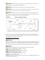
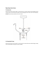
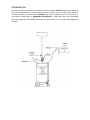
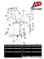
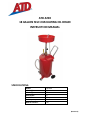
 ATD‐5200 18 GALLON SELF‐EVACUATING OIL DRAIN INSTRUCTION MANUAL SPECIFICATIONS: Model: Min Height: Max Height: Bowl Depth: Bowl Diameter: Tank Capacity: Max Air Pressure: ATD‐5200 46” 76” 5.5” 15” 18 Gallon 7 PSI (REV 05‐13) General Safety Warnings: WARNING: The instructions and warnings contained in this manual should be read and understood before using or operating this tool. Do not allow anyone to use or operate this tool until they have read this manual and have developed a thorough understanding of how this tool works. Failure to observe any of the following instructions could result in severe personal injury to tool user and bystanders, or cause damage to the tool and property. Keep this manual for future reference. Note: The warnings and cautions discussed in this instruction manual cannot cover all possible conditions and situations that may occur. It must be understood by the operator that common sense and caution are factors which cannot be built into this product, but must be supplied by the operator. WARNING: Use safety equipment. User and bystanders should use safety goggles or safety glasses with side shields which comply with current national standards, or when needed, a face shield. Use an ANSI approved dust mask or respirator when working around metal, wood, and chemical dusts and mists. This applies to all persons in the work area. Also use non‐skid safety shoes, hardhat, gloves, dust collection systems, and hearing protection when appropriate. WARNING: Keep bystanders and children out of the work area while operating this tool. WARNING: Always keep your work area clean, uncluttered, and well lit. Cluttered or dark areas invite accidents and injuries. DO NOT work on floor surfaces that are slippery. WARNING: Do not operate this tool if you are tired or under the influence of alcohol, drugs, or medications that could affect your ability to use the tool properly. WARNING: Dress properly. Do not wear loose clothing or jewelery as they can be caught in moving parts. Wear restrictive hair covering to contain long hair. WARNING: Do not reach over or across running machines. Keep proper footing and balance at all times. Non‐skid footwear is recommended when working. Air Tool Specific Warnings: WARNING: Air under pressure can cause severe injury. Never point an air tool at anyone or direct air at yourself or others. It could cause serious injury. WARNING: Always turn off the air supply, drain the hose of air pressure and detach the tool from the air supply before installing, removing or adjusting any accessory on this tool, or before performing any maintenance on this tool. Failure to do so could result in injury. WARNING: Always check for damaged, frayed or loose hoses and fittings. Have any defective or damaged parts replaced immediately by qualified personnel. WARNING: Always use air hose and couplings with a minimum working pressure rating of at least 1‐1/2 times the maximum working pressure rating of the tool. WARNING: Do not depress the tool trigger/lever when connecting the air supply hose. WARNING: Do not lock, tape, wire, or otherwise disable the “ON/OFF” valve in the “ON” position. The trigger must always be free to return to the “OFF” position when released. WARNING: When the tool is not in use, shut off the air supply and press the trigger/lever to drain the air supply line. If the tool is not to be used for a period of time, first lubricate, disconnect from the air supply and store in a clean and dry location at average room temperature. NOTE: Typical Air Supply Installation Always use clean, dry air. Dust, corrosive fumes and/or water in the airline will cause damage to the tool. Drain the air tank daily. Clean the air inlet filter screen on at least a weekly schedule. The recommended hook up procedure can be viewed in the above figure. ATD‐5200 Specific Warnings: INSPECTION: Check for worn parts, air leaks, and damaged, loose or missing parts before operating. Check tank operation by connecting air to air nipple and closing ball valve. Verify that there is sufficient air flow coming from nozzle/hose assembly. An annual tank/component inspection is recommended. WARNING: Failure to heed the following may result in personal injury and/or property damage. NEVER leave unit unattended when operating or evacuating. NEVER use near open flame or heat source. ALWAYS raise drain bowl and close main valve before emptying. ALWAYS disconnect air supply after emptying. NEVER use unit for handling highly volatile fuels and fluids. USE ONLY the nozzle assembly provided. DO NOT tamper with or remove the pop‐off valve and preset, non adjustable regulator as they have been installed for protection. WARNING: MAX Pressure – 7 psi. Never pressurize tank with ball valve open. If used oil does not evacuate tank upon pressurization, check that ball valve is fully closed (handle in horizontal position). If this does not correct the problem, remove the unit from service and contact an authorized service center for repair. If the pop‐off valve relieves ANY air pressure from the tank, remove the unit from service and contact an authorized service center for repair. WARNING: ALWAYS remove oil drain and any tools, jacks, etc. and from under vehicle before lowering lift. ASSEMBLY 1. Remove tank from box. Slide 1/2” diameter steel axle (#25) through axle housing on bottom of tank (#15). Place wheel (#21) on axle (#25), securing with washer and retaining ring (#22 & #23). Repeat for other wheel. 2. Remove wood spacers from casters brackets. Slide stud of caster (#20) through bracket, securing with washer and nut (#18 & #19). Repeat for other caster. 3. Place TFE pipe sealant on thread of 3/4” NPT barbed fitting (#17) and screw into lower fitting on side of tank (#15). Slide loop clamp (#16) over end of hose (#14). Then push end of hose (#14) over barbed fitting (#17). Slide the loop clamp (#16) down over hose (#14) and barbed fitting (#17) and tighten for use. 4. Place loop clamp (#13) around tubing and fasten to tank (#15). Continually keeping tension on hose to keep as straight as possible. 5. Place TFE pipe sealant on 1‐1/2” NPT nipple (#5) on top dome of tank. Screw 1‐1/2” ball valve (#7) into tank (#15). Screw clamping knob (#4) into 4” pipe nipple (#3). (NOTE: Only one of the four holes in 4” nipple is threaded. The other 3 holes are non‐threaded pressure relief ports.) 6. Place TFE pipe sealant on funnel assembly (#1). Then put drain tube (#2) and funnel assembly (#1) into tank (#15) through the 4” nipple (#3) and ball valve (#7) assembly. All fittings should be tight so as to prevent any leaking. Operating Instructions: TO DRAIN OIL: With valve fully open (Valve handle in vertical position), raise drain bowl to desired height and lock in place. Drain oil into bowl/tank assembly. Check sight gauge tube on back side of tank frequently. DO NOT fill tank above maximum oil level as shown. TO TRANSPORT TANK With valve fully open (valve handle in vertical position), lower drain bowl to desired height. Always use the tank handle to transport the tank assembly. TO EVACUATE OIL Evacuate used oil from tank when maximum oil level is obtained. DO NOT fill tank above maximum oil level as indicated above. Raise drain bowl and lock in place, close valve fully (valve handle in horizontal position), and place nozzle SECURELY into used oil collection reservoir. Connect air to inlet nipple and discharge oil. MAXIMUM AIR PRESSURE – 7 PSI. Never leave unit unattended when evacuating oil. Immediately disconnect air supply when oil is no longer discharging into reservoir. ATD-5200
ITEM#
1
2
3
4
5
6
7
8
9
10
11
12
13
14
ORDERING PART#
PRT5200-01
PRT5200-02
PRT5200-03
PRT5200-04
PRT5200-05
PRT5200-06
PRT5200-07
PRT5200-08
PRT5200-09
PRT5200-10
PRT5200-11
PRT5200-HK
PRT5200-HK
PRT5200-14
PART DESCRIPTION
FUNNEL ASSEMBLY
DRAIN TUBE
4” NIPPLE
KNOB
HEX BUSH
1/4" BALL VALVE
1-1/2" BALL VALVE
TUBE CONNECTOR
HEX CONNECTOR
HANDLE
BLEEDER VALVE
SCREW
LOOP CLAMP
HOSE/NOZZLE ASSEMBLY
ITEM#
15
16
17
18
19
20
21
22
23
24
25
26
27
ORDERING PART#
PRT5200-15
PRT5200-HK
PRT5200-17
PRT5200-HK
PRT5200-HK
PRT5200-20
PRT5200-21
PRT5200-HK
PRT5200-HK
PRT5200-24
PRT5200-25
PRT5200-26
PRT5200-27
PART DESCRIPTION
TANK ASSEMBLY
LOOP CLAMP
BARBED FITTING
NUT
WASHER
CASTER
WHEEL
WASHER
RETAINING RING
SCREW PLUG
AXLE
CONNECTOR
PARTS TRAY
(REV 05-13)