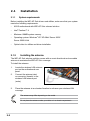
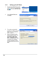
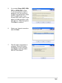
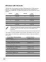
1
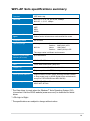
E2949
®
User Guide
E2949
Third Edition V3
December 2006
Copyright © 2006 ASUSTeK COMPUTER INC. All Rights Reserved.
No part of this manual, including the products and software described in it, may be reproduced,
transmitted, transcribed, stored in a retrieval system, or translated into any language in any form or by any
means, except documentation kept by the purchaser for backup purposes, without the express written
permission of ASUSTeK COMPUTER INC. (“ASUS”).
Product warranty or service will not be extended if: (1) the product is repaired, modified or altered, unless
such repair, modification of alteration is authorized in writing by ASUS; or (2) the serial number of the
product is defaced or missing.
ASUS PROVIDES THIS MANUAL “AS IS” WITHOUT WARRANTY OF ANY KIND, EITHER EXPRESS
OR IMPLIED, INCLUDING BUT NOT LIMITED TO THE IMPLIED WARRANTIES OR CONDITIONS OF
MERCHANTABILITY OR FITNESS FOR A PARTICULAR PURPOSE. IN NO EVENT SHALL ASUS, ITS
DIRECTORS, OFFICERS, EMPLOYEES OR AGENTS BE LIABLE FOR ANY INDIRECT, SPECIAL,
INCIDENTAL, OR CONSEQUENTIAL DAMAGES (INCLUDING DAMAGES FOR LOSS OF PROFITS,
LOSS OF BUSINESS, LOSS OF USE OR DATA, INTERRUPTION OF BUSINESS AND THE LIKE),
EVEN IF ASUS HAS BEEN ADVISED OF THE POSSIBILITY OF SUCH DAMAGES ARISING FROM ANY
DEFECT OR ERROR IN THIS MANUAL OR PRODUCT.
SPECIFICATIONS AND INFORMATION CONTAINED IN THIS MANUAL ARE FURNISHED FOR
INFORMATIONAL USE ONLY, AND ARE SUBJECT TO CHANGE AT ANY TIME WITHOUT NOTICE,
AND SHOULD NOT BE CONSTRUED AS A COMMITMENT BY ASUS. ASUS ASSUMES NO
RESPONSIBILITY OR LIABILITY FOR ANY ERRORS OR INACCURACIES THAT MAY APPEAR IN THIS
MANUAL, INCLUDING THE PRODUCTS AND SOFTWARE DESCRIBED IN IT.
Products and corporate names appearing in this manual may or may not be registered trademarks or
copyrights of their respective companies, and are used only for identification or explanation and to the
owners’ benefit, without intent to infringe.
ii
Contents
Features
About this guide.......................................................................................... iv
WiFi-AP Solo specifications summary....................................................... v
Chapter 1: Product introduction
1.1
Welcome!....................................................................................... 1-2
1.3
LED and antenna port................................................................... 1-4
1.2
1.4
Features......................................................................................... 1-2
Choosing an appropriate wireless network................................ 1-5
1.4.1
Access Point Mode (AP Mode)........................................ 1-6
1.4.3
Ad-hoc mode.................................................................... 1-7
1.4.2
Infrastructure mode.......................................................... 1-7
Chapter 2: Installation
2.1
Installation..................................................................................... 2-2
2.1.1
System requirements....................................................... 2-2
2.1.3
Signal range..................................................................... 2-3
2.1.2
2.2
Installing the antenna....................................................... 2-2
Driver and utilities installation..................................................... 2-4
Chapter 3: Setting up
3.1
3.2
3.3
About the setup utilities............................................................... 3-2
Setting up with WiFi-AP Solo Wizard.......................................... 3-3
3.2.1
3.2.2
Setting up infrastructure of the station mode .................. 3-6
Setting up via setup utility........................................................... 3-7
3.3.1
3.3.2
3.3.3
3.4
Setting up the AP Mode .................................................. 3-4
3.3.4
How to launch the WiFi-AP Solo...................................... 3-7
Utility Windows ............................................................... 3-7
Setting up AP Mode ...................................................... 3-12
Setting up the station mode........................................... 3-14
Setting up wireless security....................................................... 3-17
Glossary
Glossary..................................................................................................... 4-2
Appendix
Wireless LAN Channels............................................................................A-2
Safety Statements......................................................................................A-4
iii
About this guide
This user guide contains the information you need to install and configure your
ASUS WiFi-AP Solo wireless solution.
How this guide is organized
This guide contains the following parts:
•
Chapter 1: Product introduction
This chapter describes the general features of the ASUS WiFi-AP Solo
wireless solution. The chapter also presents the LED indications, and
recommended WiFi-AP Solo network settings.
•
Chapter 2: Installation
•
Chapter 3: Setting up
•
Glossary
•
Appendix
This chapter provides step by step instructions on installing the wireless LAN
adapter drivers and software applications using the support CD.
This chapter provides information on how to set up the WiFi-AP Solo in your
home or office network using the setup wizard.
This chapter provides definition for the technical terms used in this manual.
The Appendix lists the wireless LAN channels available for use in your
country or location and safety statements.
Conventions used in this guide
To make sure that you perform certain tasks properly, take note of the following
symbols used throughout this manual.
DANGER/WARNING: Information to prevent injury to yourself when trying to complete a task.
IMPORTANT: Information that you MUST follow to complete a task.
iv
CAUTION: Information to prevent damage to the components when trying to complete a task.
NOTE: Tips and additional information to aid in completing a task.
WiFi-AP Solo specifications summary
Standard
IEEE 802.11b/g
Data rate
802.11g: 6, 9, 12, 18, 24, 36, 48, 54Mbps
802.11b: 1, 2, 5.5, 11Mbps
Security
Access Point mode:
WEP
WPA
WPA2
Network architechture
types
Access point mode
Station mode: Infrastructure mode and Ad-Hoc mode
Frequency band
2.4~2.5GHz
Operating range
802.11g
Indoor: 80ft (30m)
Outdoor: 200ft (60m) LOS*
802.11b
Indoor: 130ft (40m)
Outdoor: 1000ft (310m) LOS*
The range varies in different environments
Number of connected
devices (AP mode)
up to 64 stations
Antenna
ASUS WiFi-AP Solo omni-directional antenna
LED
Green data transmission (AIR) LED
Support OS
Windows® 2003, XP, XP-64bit, 2003-64bit
Compatibility
Fully compatible with IEEE802.11b/g standard products
ASUS special features
Supports ASUS EZ WiFi mode: Running wireless network
in sleep mode (only on ASUS Digital Home motherboards
except for P5LD2-VM DH and N4L-VM DH)
Software support
ASUS WiFi-AP Solo Wizard
ASUS WiFi-AP Solo
* The Vista driver is ready when the Windows® Vista Operating System (OS)
is launched. Visit the ASUS website (www.asus.com) to download the latest
driver.
* LOS=Light of Sight
* The specifications are subject to change without notice.
vi
Chapter 1
This chapter describes the general
features of the ASUS WiFi-AP Solo
wireless solution. The chapter also
presents the LED indications, and
recommended WiFi-AP Solo network
settings.
Product introduction
1-1
1.1
Welcome!
Thank you for choosing the ASUS WiFi-AP Solo wireless solution!
The WiFi-AP Solo is an easy-to-use wireless local area network (WLAN) adapter
designed for home or office use. The WiFi-AP Solo is backward compatible with
the earlier IEEE 802.11b standard allowing seamless integration of both wireless
LAN standards in a single network.
The WiFi-AP Solo also supports several wireless network configuration including
Infrastructure, Ad-hoc, and Access Point. This gives you flexibility to your existing
or future wireless network configurations.
To provide efficient security to your wireless communication, WiFi-AP Solo
employs both 64-bit/128-bit Wired Equivalent Privacy (WEP) and Wi-Fi Protected
Access (WPA/WPA2) encryptions.
With these and many more, ASUS WiFi-AP Solo is sure to keep you ahead in the
world of wireless computing.
1.2
Features
ASUS EZ WiFi mode
Users will be able to play LAN games, connect to the Internet, access and share
printers, and use Skype from anywhere within the range.
WiFi-AP Solo can provide these functions even when the PC is in the sleep mode.
Hence, users can use Skype instead of the traditional long distance telephone
service.
The ASUS EZ WiFi mode will work only on PCs with ASUS Digital Home
motherboards, except for P5LD2-VM DH and N4L-VM DH motherboards.
No hardware installation
Because the WiFi-AP Solo wireless LAN adapter comes embedded in your ASUS
motherboard, no hardware installation is needed. Just install the drivers and utilities
from the motherboard support CD and start computing wirelessly in no time.
1-2
54Mbps speed advantage
With data transmission rate up to five times faster than IEEE 802.11b standards,
the WiFi-AP Solo breaks the wireless data transmission speed barrier to give you
faster Internet connection and file sharing capabilities.
Easy integration
The WiFi-AP Solo is compatible with all IEEE 802.11b devices so you can still use
your IEEE 802.11b devices in the WiFi-AP Solo network.
Access point mode function
In AP Mode, WiFi-AP Solo can support up to 64 stations with wireless LAN
adapters making it an ideal solution for homes and offices with single Internet
connection or network printer.
Moveable omni-directional antenna
A moveable, omni-directional antenna comes with your WiFi-AP Solo to maximize
your wireless coverage.
1-3
1.3
LED and antenna port
The WiFi-AP Solo comes with a green data transmission LED (AIR) and an
antenna port located at the motherboard rear panel.
Antenna port AIR LED
•
•
The location of the WiFi-AP Solo data transmission LED and antenna port may vary on motherboard models.
The back I/O may vary depending on the models.
LED indicators
Refer to the table below for LED indications.
LED
Air LED
1-4
Status
On
Off
Blinking quickly
Blinking slowly
Indication
Power on but no data activity.
Power off or no wireless connection.
Transmitting and/or receiving data.
Site survey.
1.4
Choosing an appropriate wireless network
You can use the ASUS WiFi-AP Solo in various wireless network configurations. It
is recommended that you select the most appropriate configuration for your home or
office network before setting up the WiFi‑AP Solo.
The following pictures and descriptions are for reference only and may not
exactly match your actual network configuration.
Select Mode
AP Mode
Station Mode
1-5
1.4.1
Access Point Mode (AP Mode)
If you wish to share the Internet access with the wireless stations in your
environment, you can configure the WiFi-AP Solo in an access point mode (AP
Mode). In this mode, the WiFi-AP Solo becomes the wireless access point that
provides local area network and Internet access for your wireless stations.
The requirement of using AP Mode function is an onboard Ethernet LAN adapter
with the driver properly installed.
The AP Mode feature is ideal for home/SOHO networks with several computers, a
shared printer, and a shared Internet connection.
˝
Internet
ADSL or Cable
Modem (if any)
Printer 1
WiFi-AP Solo
MODE
Station 4
Station 1
Station 3
Station 2
1-6
1.4.2
Station mode
The station mode is centered on
a wireless access point (AP) that
provides Internet access and LAN
communication for the wireless
stations. In station mode, the wireless
LAN stations communicate with each
other via the wireless AP.
In this mode, your WiFi-AP Solo
acts as a wireless adapter. It
communicates with the LAN
computers and accesses Internet
through the wireless AP.
Internet
˝
ADSL or Cable
Modem (if any) Access Point
Station 1
WiFi-AP Solo
Station 2
In the station mode, use the Windows® Zero Configuration to set up your
WiFi-AP Solo.
1-7
1-8
Chapter 2
This chapter provides step by step
instructions on installing the WiFi-AP Solo
drivers and utilities to your computer. This
part also provides information on installing
the antenna.
Installation
2-1
2.1
Installation
2.1.1
System requirements
Before installing the WiFi-AP Solo drivers and utilities, make sure that your system
meets the following requirements.
•
ASUS motherboard with WiFi-AP Solo onboard solution
•
Intel® Pentium™ 4
• Minimum 128MB system memory
•
Operating system: Windows® XP/ XP-64bit/ Server 2003/
Server 2003 64-bit
•
Optical drive for utilities and driver installation
2.1.2
Installing the antenna
The WiFi-AP Solo wireless solution comes with an omni-directional and moveable
antenna to maximize the WiFi-AP Solo coverage.
To install the antenna:
1.
2.
3.
Locate the wireless LAN antenna
port on the motherboard rear
panel.
Connect the antenna twiston connector (female) to the
wireless LAN antenna port
(male).
Place the antenna at an elevated location to enhance your wireless LAN
coverage.
The antenna may differ depending on the model.
Do not place the antenna under your table or in a closed compartment.
2-2
2.1.3
Signal range
The signal range of WiFi-AP Solo depends on the operating environment.
Obstacles such as walls and metal barriers could reflect or absorb radio signals.
Devices such as microwave stove can also greatly interfere with the wireless
network.
Signal range:
802.11g: Indoor 80ft (30m), outdoor (LOS, Light-Of-Sight) 200ft (60m)
802.11b: Indoor 130ft (40m), outdoor (LOS, Light-Of-Sight) 1000ft (310m)
By default, the device automatically adjusts the data rate and the closer the
wireless station is, the better signal and transmit speed it receives. To improve your
wireless transmission, move your wireless stations closer to the WiFi-AP Solo.
2-3
2.2
Driver and utilities installation
•
The contents of the motherboard support CD are subject to change without
notice. Visit the ASUS website for driver/utilities updates.
•
If you use a Windows® operating system, your computer auto‑detects the
WiFi-AP Solo when system boots and displays an Add New Hardware
Wizard window. Click Cancel then proceed with the following instructions.
To install the WiFi-AP Solo driver and utilities:
1.
2.
3.
Place the motherboard support CD to the optical drive.
The CD automatically displays the Drivers menu if Autorun is enabled in your
computer. Click the wireless driver and follow screen instructions to install the
WiFi-AP Solo driver.
Select the driver / utility menu in the support CD and click to install the WiFiAP Solo utility.
If Autorun is disabled in your computer, locate the Wireless folder under the
root directory of the support CD, then double click the Setup.exe file to begin
installation.
To use soft AP function, you may need to install Ethernet adapter driver.
2-4
Chapter 3
This chapter provides information on how
to set up the WiFi-AP Solo in your home or
office network.
Setting up
3-1
3.1
About the setup utilities
After you have installed the WiFi-AP Solo drivers and utilities to your system, you
are now ready to setup the WiFi-AP Solo in your network.
Make sure that you have selected the most appropriate configuration for your
wireless network before you proceed. Refer to section 1.4 for details.
Make sure you have connected the supplied antenna to the antenna connector
on the motherboard, or the WiFi-AP Solo may not be able to detect other
wireless devices in your environment.
The WiFi-AP Solo provides two configuration approaches: the setup wizard and the
setup utility. The former scheme provides an easy approach to the most frequently
used functions while the latter allows configuring all the functions, including the
advanced settings.
For normal users, the setup wizard helps to:
1. configure the WiFi-AP Solo as an access point, or wireless station.
For advanced users, the setup utility helps to:
1.
configure the WiFi-AP Solo as an access point, or wireless station;
3.
show statistics.
2.
3-2
enable or disable the WiFi-AP Solo; and
3.2
Setting up with WiFi-AP Solo Wizard
You can create your own wireless local area network (WLAN) in your home using
the WiFi-AP Solo Access Point Mode (AP Mode) feature. Create your own WLAN
if:
1.
2.
your computer is connected to the Internet; and
the operating system of your computer is Windows® XP/ XP 64-bit/ Server
2003/ Server 2003 64-bit.
Install the WiFi-AP Solo software from the
support CD.
WiFi-AP Solo
Setup Wizard
After completing the installation, the WiFiAP Solo Setup Wizard will run automatically.
AP Mode
To use AP Mode, refer to
Section 1.4.1.
Station Mode
To use Station Mode, refer to
Section 1.4.2.
3-3
3.2.1
1.
To launch the WiFi-AP Solo setup
wizard, right-click the system tray
icon
and select WiFi-AP Solo
Wizard.
2.
Select Access Point and
click Next.
3.
The system automatically
generates an SSID for the AP
mode. You can rename the
SSID, if desired.
4.
3-4
Setting up the AP Mode
Select a Network Security
level for your AP mode. The
configurable options are
None, Share-WEP, WPAPSK, and WPA2-PSK. Refer
to section 3.4 for detailed
security information. Select
an appropriate level and click
Next.
5.
If you select Share-WEP, WPAPSK, or WPA2-PSK in Step
4, you are required to input a
password. You can choose to
configure the password in either
ASCII or HEX mode. If you
choose HEX mode, input 10 hex
digits for 64-bit encrytion, or 26
hex digits for 128-bit encryption.
Click Next to continue.
6.
Select your Internet connection
and click Next.
7.
The AP mode configuration is
complete. Record the setup
information on your note and
click Finish to quit the ASUS
WiFi-AP Solo wizard.
3-5
3.2.2
Setting up the station mode
In the Infrastructure mode, you can connect to the LAN or Internet, or both, through
a wireless AP.
1.
To launch the WiFi-AP Solo setup wizard, right-click the system tray icon
and select ASUS WiFi-AP Solo Wizard.
2.
Select Station and click Next.
3.
Click Finish.
3.
Double-click the wireless icon
on the task bar to configure
the Windows® Wireless Zero
Configuration.
Refer to Section 3.3.4 Setting up the station mode for how to use the
Windows® Wireless Zero Configuration.
3-6
3.3
Setting up via setup utility
3.3.1
How to launch Wifi-AP Solo utility
You can launch Wifi-AP Solo either from the Windows® Program menu or the tray icon.
The tray icon is an optional quick launch to be enabled by a user.
Windows® Program Menu
It is the absolute way to launch the WiFi-AP Solo from the program folder.
We recommend that you uninstall the WiFi-AP Solo utility by clicking Start >
Control Panel > Add or Remove Programs.
Tray Icon
The tray icon will be not be shown until you
enable the Show Tray Icon from the WiFi-AP
Solo. When the WiFi-AP Solo icon is shown on
the system tray, you could double-click the icon to
launch the WiFi-AP Solo Wizard.
3.3.2
Utility Windows
•
Global Control Bar
•
Show Tray Icon
Each control items on the Global Control Bar directly affects the adapter of
the management GUI.
When this item is checked, the WiFi-AP Solo icon will appear on the system
tray located at the right and lower corner of your Windows screen.
3-7
•
•
Radio Off
When this item is checked, the radio
is turned off to save power. When the
radio is off, the links with other wireless
network nodes are disconnected.
Disable Adapter
When this item is checked, the wireless
LAN adapter is disabled to increase
performance in terms of better system
resource management and CPU
utilization.
If the wireless configuration is in AP mode, checking Radio Off will cause the
sub-network belonging to the AP to disconnect with the Internet/intranet.
Status page
• Manufacturer: ASUS
•
Short Radio Header
•
•
•
• • • • • • • •
• • • 3-8
NDIS Driver Version
Data Encryption: Current encryption
mode.
Authentication: authentication state
Channel Set: selected channel plan
currently. Please reference Appendix-A
with the detail comparisons.
MAC Address: MAC address of this adapter.
Data Rate: wireless LAN transition speed
Channel (Frequency): current channel number
Status: wireless network status
Network Name (SSID): name of connecting access point
Basic Service Set Identification (BSSID)
Network Type: indicate current network configuration type
Power Save Mode: current setting power save mode
Associated AP MAC: MAC address of connecting access point
Associated AP IP: IP address of connecting access point
• Up Time
Config page
This page displays the basic information of
the WiFi-AP Solo:
Statistics page
You could watch the Tx/Rx status of current
wireless connection. It provides a statistic
analysis of packet transition.
Advanced page
This page presents all the access points in
the system.
Internet Connection Sharing (ICS)
page
This page is enabled when the WiFi-AP Solo
is switched to AP mode. This page allows
you to configure your Internet connection
which you wish to share.
3-9
3.3.3
Setting up AP Mode
Open the setup utility by double-clicking the utility icon on the
desktop. The setup utility contains six buttons - Status, Config,
Survey, Statistics, Advanced and ICS in the left column. The Survey
button is greyed out in AP mode and the ICS button is disabled
when in the station mode.
3-10
1.
Open the setup utility and click
Config button. Click the AP/
Station Mode switch button - To
Access Point Mode. The WiFiAP Solo is switched to AP mode
in several seconds.
2.
Click ICS button to configure your
Internet connection which you
wish to share. Select the correct
connection and click Apply
button.
3.
Click Config button and enter
the Network Monitor tab. Click
Config button to enter the
Wireless Network Properties
page of the AP mode.
4.
You are directed to the Wireless
Network Properties page to set
up the AP mode. In this page,
you can change the SSID, select
the communication channel and
specify the network security. When
configuration is complete, click OK
to apply the settings and return to
the setup wizard.
5.
The AP mode configuration is
finished. You can view in the
Association Table of the Config
page all the wireless stations that
have connected to the WiFi-AP
Solo (AP mode).
3-11
3.3.4
Setting up the station mode
Open the setup utility by double-clicking the utility icon on the desktop. A
message pops up asking you to set up the station mode via the Windows®
Wireless Zero Configuration (WZC) service.
The actual screens of Windows® Wireless Zero Configuration service may differ
according to the Operating System (OS) of your computer.
To configure the Windows® Wireless Zero Configuration (WZC) service, follow the
instruction below to make the settings.
1. Double-click the wireless network
icon on the task bar to view
available networks.Select the AP
and click Connect.
2. A window prompts out asking
you for the key if you have set
up encryption on your wireless
router, input the keys and click
Connect. The connection is
complete.
3-12
To set up the wireless connection properties, right-click the wireless icon on the
task bar and select Open Network Connection. Then right-click the network
connection icon and select Properties to open the Wireless Network Connection
Status page.
1.
The General page shows status,
duration, speed, and signal
strength. Signal strength is
represented by green bars with
5 bars indicating excellent signal
and 1 bar meaning poor signal.
2.
Select “Wireless Networks” tab
to show Preferred networks.
Use the Add button to add the
“SSID” of available networks and
set the connection preference
order with the Move up and
Move down buttons. The radio
tower with a signal icon identifies
the currently connected access
point. Click Properties to set the
authentication of the wireless
connection.
3-13
3.
The Authentication page allows
you to add security settings.
Read Windows help for more
information.
4.
The Advanced page allows
you to set firewall and sharing.
Read Windows help for more
information.
In the station mode, the Windows® Zero Configuration does not support WPA2
PSK and cannot connect the access point with WPA2 PSK. Visit the Microsoft
download center to download the WPA2 package.
3-14
3.4
Setting up wireless security
To protect your wireless network, you need to setup a security mechanism on your
WiFi-AP Solo. Under AP mode, only Open, Shared, and WPA-PSK are supported.
Under Station mode, all the security modes listed below are supported.
Network authentication
Network authentication uses certain types of mechanism to identify authenticated wireless
clients. WiFi-AP Solo supports the following authentication methods:
Open:
This option disables authentication protection for your wireless network. Under the Open mode, any IEEE802.11b/g wireless client can connect to
your wireless network.
Shared: Shared means using the same WEP keys for authentication and encryption.
802.1X: 802.1X uses RADIUS (Remote Access Dial-Up User Service) server to authenticate wireless clients with a user name and password. It can authenticate user with different levels of access right.
WPA: WPA stands for WiFi-Protected Access. WPA provides two security
modes for Home/SOHO user and enterprise network. The former solution
adopts Pre-Shared Key for authentication, and the later uses the existing
802.1X RADIUS server in the enterprise network to process the
authentication requests.
WPA - PSK: WPA-PSK (Pre-Shared Key) is the solution for home and SOHO
users who have no 802.11X authentication server within the
LAN. To setup WPA-PSK, you need to input a passphrase and let
the system generate the key. Combination of letters, numbers and non
alphnumeric charecters is recommended for ensuring security.
3-15
Encryption
Encryption is used to convert plain text data into unreadable codes with certain
type of algorithm before capsulation for wireless transmission. WiFi-AP Solo
supports the following encryption methods:
WEP:
WEP stands for Wired Equivalent Privacy. It uses 64 or 128-bit
static keys. You can let the system generate the WEP keys by inputting a
Passphrase.
TKIP:
AES:
Temporal Key Integrity Protocol (TKIP) dynamically generates unique
keys to encypt every data packet in a wireless session.
Advanced Encryption Standard (AES) is a dependable encryption
adopted in WPA2 or IEEE802.11i standard. It offers stronger protection
and greatly increases the complexity of wireless encryption.
TKIP + AES: For a network where WPA clients (using TKIP encryption) and WPA2
3-16
clients (using AES encryption) co-exit. Select this option to enable both.
Glossary
4-1
Access Point (AP)
A networking device that seamlessly connects wired and wireless networks. Access
Points combined with a distributed system support the creation of multiple radio
cells that enable roaming throughout a facility.
Ad Hoc
A wireless network composed solely of stations within mutual communication range
of each other (no Access Point).
Basic Rate Set
This option allows you to specify the data transmission rate.
Basic Service Area (BSS)
A set of stations controlled by a single coordination function.
Broadband
A type of data transmission in which a single medium (such as cable) carries
several channels of data at once.
Channel
An instance of medium use for the purpose of passing protocol data units that
may be used simultaneously, in the same volume of space, with other instances
of medium use (on other channels) by other instances of the same physical layer,
with an acceptably low frame error ratio due to mutual interference.
Client
A client is the desktop or mobile PC that is connected to your network.
COFDM (for 802.11a or 802.11g)
Signal power alone is not enough to maintain 802.11b-like distances in an
802.11a/g environment. To compensate, a new physical-layer encoding technology
was designed that departs from the traditional direct-sequence technology being
deployed today. This technology is called COFDM (coded OFDM). COFDM was
developed specifically for indoor wireless use and offers performance much
superior to that of spread-spectrum solutions. COFDM works by breaking one
high-speed data carrier into several lower-speed subcarriers, which are then
transmitted in parallel. Each high-speed carrier is 20 MHz wide and is broken
up into 52 subchannels, each approximately 300 KHz wide. COFDM uses 48 of
these subchannels for data, while the remaining four are used for error correction.
COFDM delivers higher data rates and a high degree of multipath reflection
recovery, thanks to its encoding scheme and error correction.
4-2
Each subchannel in the COFDM implementation is about 300 KHz wide. At the low
end of the speed gradient, BPSK (binary phase shift keying) is used to encode 125
Kbps of data per channel, resulting in a 6,000-Kbps, or 6 Mbps, data rate. Using
quadrature phase shift keying, you can double the amount of data encoded to 250
Kbps per channel, yielding a 12-Mbps data rate. And by using 16-level quadrature
amplitude modulation encoding 4 bits per hertz, you can achieve a data rate of
24 Mbps. The 802.11a/g standard specifies that all 802.11a/g-compliant products
must support these basic data rates. The standard also lets the vendor extend the
modulation scheme beyond 24 Mbps. Remember, the more bits per cycle (hertz)
that are encoded, the more susceptible the signal will be to interference and fading,
and ultimately, the shorter the range, unless power output is increased.
Default Key
This option allows you to select the default WEP key. This option allows you to
use WEP keys without having to remember or write them down. The WEP keys
generated using the Pass Phrase is compatible with other WLAN products. The
Pass Phrase option is not as secure as manual assignment.
Device Name
Also known as DHCP client ID or network name. Sometimes provided by an ISP
when using DHCP to assign addresses.
DHCP (Dynamic Host Configuration Protocol)
This protocol allows a computer (or many computers on your network) to be
automatically assigned a single IP address from a DHCP server.
DNS Server Address (Domain Name System)
DNS allows Internet host computers to have a domain name and one or more IP
addresses. A DNS server keeps a database of host computers and their respective
domain names and IP addresses, so that when a user enters a domain name into
the Internet browser, the user is sent to the proper IP address. The DNS server
address used by the computers on your home network is the location of the DNS
server your ISP has assigned.
DSL Modem (Digital Subscriber Line)
A DSL modem uses your existing phone lines to transmit data at high speeds.
Direct-Sequence Spread Spectrum (for 802.11b)
Spread spectrum (broadband) uses a narrowband signal to spread the transmission
over a segment of the radio frequency band or spectrum. Direct-sequence is a
spread spectrum technique where the transmitted signal is spread over a particular
frequency range.
4-3
Direct-sequence systems communicate by continuously transmitting a redundant
pattern of bits called a chipping sequence. Each bit of transmitted data is mapped
into chips and rearranged into a pseudorandom spreading code to form the
chipping sequence. The chipping sequence is combined with a transmitted data
stream to produce the output signal.
Wireless mobile clients receiving a direct-sequence transmission use the spreading
code to map the chips within the chipping sequence back into bits to recreate the
original data transmitted by the wireless device. Intercepting and decoding a directsequence transmission requires a predefined algorithm to associate the spreading
code used by the transmitting wireless device to the receiving wireless mobile
client.
This algorithm is established by IEEE 802.11b specifications. The bit redundancy
within the chipping sequence enables the receiving wireless mobile client to
recreate the original data pattern, even if bits in the chipping sequence are
corrupted by interference. The ratio of chips per bit is called the spreading ratio.
A high spreading ratio increases the resistance of the signal to interference. A
low spreading ratio increases the bandwidth available to the user. The wireless
device uses a constant chip rate of 11Mchips/s for all data rates, but uses different
modulation schemes to encode more bits per chip at the higher data rates. The
wireless device is capable of an 11 Mbps data transmission rate, but the coverage
area is less than a 1 or 2 Mbps wireless device since coverage area decreases as
bandwidth increases.
Encryption
This provides wireless data transmissions with a level of security. This option
allows you to specify a 64-bit or a 128-bit WEP key. A 64-bit encryption contains
10 hexadecimal digits or 5 ASCII characters. A 128-bit encryption contains 26
hexadecimal digits or 13 ASCII characters.
64-bit and 40-bit WEP keys use the same encryption method and can interoperate
on wireless networks. This lower level of WEP encryption uses a 40-bit (10
hexadecimal digits assigned by the user) secret key and a 24-bit Initialization
Vector assigned by the device. 104-bit and 128-bit WEP keys use the same
encryption method.
All wireless clients in a network must have identical WEP keys with the access
point to establish connection. Keep a record of the WEP encryption keys.
Extended Service Set (ESS)
A set of one or more interconnected basic service set (BSSs) and integrated local
area networks (LANs) can be configured as an Extended Service Set.
ESSID (Extended Service Set Identifier)
You must have the same ESSID entered into the gateway and each of its wireless
clients. The ESSID is a unique identifier for your wireless network.
4-4
Ethernet
The most widely used LAN access method, which is defined by the IEEE 802.3
standard. Ethernet is normally a shared media LAN meaning all devices on the
network segment share total bandwidth. Ethernet networks operate at 10Mbps
using CSMA/CD to run over 10-BaseT cables.
Firewall
A firewall determines which information passes in and out of a network. NAT can
create a natural firewall by hiding a local network’s IP addresses from the Internet.
A Firewall prevents anyone outside of your network from accessing your computer
and possibly damaging or viewing your files.
Gateway
A network point that manages all the data traffic of your network, as well as to the
Internet and connects one network to another.
IEEE
The Institute of Electrical and Electronics Engineers. The IEEE sets standards
for networking, including Ethernet LANs. IEEE standards ensure interoperability
between systems of the same type.
IEEE 802.11
IEEE 802.xx is a set of specifications for LANs from the Institute of Electrical
and Electronic Engineers (IEEE). Most wired networks conform to 802.3, the
specification for CSMA/CD based Ethernet networks or 802.5, the specification for
token ring networks. 802.11 defines the standard for wireless LANs encompassing
three incompatible (non-interoperable) technologies: Frequency Hopping Spread
Spectrum (FHSS), Direct Sequence Spread Spectrum (DSSS), and Infrared.
802.11 specifies a carrier sense media access control and physical layer
specifications for 1 and 2 Mbps wireless LANs.
IEEE 802.11a
Compared with 802.11b: The 802.11b standard was designed to operate in
the 2.4-GHz ISM (Industrial, Scientific and Medical) band using direct-sequence
spread-spectrum technology. The 802.11a standard, on the other hand, was
designed to operate in the more recently allocated 5-GHz UNII (Unlicensed
National Information Infrastructure) band. And unlike 802.11b, the 802.11a standard
departs from the traditional spread-spectrum technology, instead using a frequency
division multiplexing scheme that's intended to be friendlier to office environments.
The 802.11a standard, which supports data rates of up to 54 Mbps, is the Fast
Ethernet analog to 802.11b, which supports data rates of up to 11 Mbps. Like
Ethernet and Fast Ethernet, 802.11b and 802.11a use an identical MAC (Media
Access Control). However, while Fast Ethernet uses the same physical-layer
encoding scheme as Ethernet (only faster), 802.11a uses an entirely different
encoding scheme, called OFDM (orthogonal frequency division multiplexing).
4-5
The 802.11b spectrum is plagued by saturation from wireless phones, microwave
ovens and other emerging wireless technologies, such as Bluetooth. In contrast,
802.11a spectrum is relatively free of interference.
The 802.11a standard gains some of its performance from the higher frequencies
at which it operates. The laws of information theory tie frequency, radiated power
and distance together in an inverse relationship. Thus, moving up to the 5-GHz
spectrum from 2.4 GHz will lead to shorter distances, given the same radiated
power and encoding scheme.
Compared with 802.11g: 802.11a is a standard for access points and radio NICs
that is ahead of 802.11g in the market by about six months. 802.11a operates in the
5GHz frequency band with twelve separate non-overlapping channels. As a result,
you can have up to twelve access points set to different channels in the same
area without them interfering with each other. This makes access point channel
assignment much easier and significantly increases the throughput the wireless
LAN can deliver within a given area. In addition, RF interference is much less likely
because of the less-crowded 5 GHz band.
IEEE 802.11b
In 1997, the Institute of Electrical and Electronics Engineers (IEEE) adopted the
802.11 standard for wireless devices operating in the 2.4 GHz frequency band. This
standard includes provisions for three radio technologies: direct sequence spread
spectrum, frequency hopping spread spectrum, and infrared. Devices that comply
with the 802.11 standard operate at a data rate of either 1 or 2 Mbps.
In 1999, the IEEE created the 802.11b standard. 802.11b is essentially identical
to the 802.11 standard except 802.11b provides for data rates of up to 11 Mbps
for direct sequence spread spectrum devices. Under 802.11b, direct sequence
devices can operate at 11 Mbps, 5.5 Mbps, 2 Mbps, or 1 Mbps. This provides
interoperability with existing 802.11 direct sequence devices that operate only at 2
Mbps.
Direct sequence spread spectrum devices spread a radio signal over a range of
frequencies. The IEEE 802.11b specification allocates the 2.4 GHz frequency band
into 14 overlapping operating Channels. Each Channel corresponds to a different
set of frequencies.
IEEE 802.11g
802.11g is a new extension to 802.11b (used in majority of wireless LANs today)
that broadens 802.11b's data rates to 54 Mbps within the 2.4 GHz band using
OFDM (orthogonal frequency division multiplexing) technology. 802.11g allows
backward compatibility with 802.11b devices but only at 11 Mbps or lower,
depending on the range and presence of obstructions.
4-6
Infrastructure
A wireless network centered about an access point. In this environment, the access
point not only provides communication with the wired network but also mediates
wireless network traffic in the immediate neighborhood.
IP (Internet Protocol)
The TCP/IP standard protocol that defines the IP datagram as the unit of
information passed across an Internet and provides the basis for connectionless
packet delivery service. IP includes the ICMP control and error message protocol
as an integral part. It provides the functional equivalent of ISO OSI Network
Services.
IP Address
An IP address is a 32-bit number that identifies each sender or receiver of
information that is sent across the Internet. An IP address has two parts: the
identifier of a particular network on the Internet and an identifier of the particular
device (which can be a server or a workstation) within that network.
ISM Bands (Industrial, Scientific, and Medicine Bands)
Radio frequency bands that the Federal Communications Commission (FCC)
authorized for wireless LANs. The ISM bands are located at 902 MHz, 2.400 GHz,
and 5.7 GHz.
ISP (Internet Service Provider)
An organization that provides access to the Internet. Small ISPs provide service
via modem and ISDN while the larger ones also offer private line hookups (T1,
fractional T1, etc.).
LAN (Local Area Network)
A communications network that serves users within a defined geographical area.
The benefits include the sharing of Internet access, files and equipment like
printers and storage devices. Special network cabling (10 Base-T) is often used to
connect the PCs together.
MAC Address (Media Access Control)
A MAC address is the hardware address of a device connected to a network.
NAT (Network Address Translation)
NAT masks a local network’s group of IP addresses from the external network,
allowing a local network of computers to share a single ISP account. This process
allows all of the computers on your home network to use one IP address. This will
enable access to the Internet from any computer on your home network without
having to purchase more IP addresses from your ISP.
4-7
NIC (Network Interface Card)
A network adapter inserted into a computer so that the computer can be connected
to a network. It is responsible for converting data from stored in the computer to the
form transmitted or received.
Packet
A basic message unit for communication across a network. A packet usually
includes routing information, data, and sometimes error detection information.
Pass Phrase
The Wireless Settings utility uses an algorithm to generate four WEP keys based
on the typed combination.
PPP (Point-to-Point Protocol)
PPP is a protocol for communication between computers using a serial interface,
typically a personal computer connected by phone line to a server.
PPPoE (Point-to-Point Protocol over Ethernet)
Point-to-Point Protocol is a method of secure data transmission. PPP using
Ethernet to connect to an ISP.
Preamble
Allows you to set the preamble mode for a network to Long, Short, or Auto. The
default preamble mode is Long.
Radio Frequency (RF) Terms: GHz, MHz, Hz
The international unit for measuring frequency is Hertz (Hz), equivalent to the
older unit of cycles per second. One megahertz (MHz) is one million Hertz. One
gigahertz (GHz) is one billion Hertz. The standard US electrical power frequency is
60 Hz, the AM broadcast radio frequency band is 0.55-1.6 MHz, the FM broadcast
radio frequency band is 88-108 MHz, and wireless 802.11 LANs operate at 2.4
GHz.
SSID (Service Set Identifier)
SSID is a group name shared by every member of a wireless network. Only client
PCs with the same SSID are allowed to establish a connection. Enabling the
Response to Broadcast SSID requests option allows the device to broadcast
its SSID in a wireless network. This allows other wireless devices to scan and
establish communication with the device. Unchecking this option hides the SSID to
prevent other wireless devices from recognizing and connecting to the device.
4-8
Station
Any device containing IEEE 802.11 wireless medium access conformity.
Subnet Mask
A subnet mask is a set of four numbers configured like an IP address. It is used to
create IP address numbers used only within a particular network.
TCP (Transmission Control Protocol)
The standard transport level protocol that provides the full duplex, stream service
on which many application protocols depend. TCP allows a process or one
machine to send a stream of data to a process on another. Software implementing
TCP usually resides in the operating system and uses the IP to transmit information
across the network.
WAN (Wide Area Network)
A system of LANs, connected together. A network that connects computers located
in separate areas, (i.e., different buildings, cities, countries). The Internet is a wide
area network.
WECA (Wireless Ethernet Compatibility Alliance)
An industry group that certifies cross-vender interoperability and compatibility
of IEEE 802.11b wireless networking products and to promote that standard for
enterprise, small business, and home environments.
WPA (Wi-Fi Protected Access)
Wi-Fi Protected Access (WPA) is an improved security system for 802.11. It is part
of the 802.11i draft security standard. WPA encompasses TKIP (Temporal Key
Integrity Protocol) along with MIC (Message Integrity Check) and other fixes to
WEP such as Weak IV (Initialization Vector) filtering and Random IV generation.
TKIP uses 802.1x to deploy and change temporary keys as opposed to static
WEP keys once used in the past. It is a significant improvement over WEP. WPA
is part of a complete security solution. WPA also requires authentication servers in
enterprise security solutions.
WLAN (Wireless Local Area Network)
This is a group of computers and other devices connected wirelessly in a small
area. A wireless network is referred to as LAN or WLAN.
4-9
4-10
Appendix
The Appendix lists the wireless LAN
channels available for use in your country
or location, and safety warning statements
A-1
Wireless LAN channels
The IEEE 802.11b/g standard for wireless LAN allocated the 2.4 GHz frequency
band into 13 overlapping operating channels. Each channel corresponds to a
different set of frequencies. The table below shows the center frequencies of each
channel.
Channel
Center
Channel
Frequency
Center
Frequency
1
2.412 GHz
8
2.447 GHz
2
2.417 GHz
9
2.452 GHz
3
2.422 GHz
10
2.457 GHz
4
2.427 GHz
11
2.462 GHz
5
2.432 GHz
12
2.467 GHz
6
2.437 GHz
13
2.472 GHz
7
2.442 GHz
14
2.484 GHz
If several Wi-Fi devices are operating in the same vicinity, the distance between
the center frequencies of channels used must be at least 25MHz to avoid
interference.
The number of channels available for the wireless LAN adapter varies by country/
region. Refer to the table below to determine the number of channels available in
your location.
Country/Region (Regulating Body)
Channels 1 to 13
Belgium (RTT&E/EMC/LVD)
Channels 1 to 13
Bulgaria (RTT&E/EMC/LVD)
Channels 1 to 13
Canada (CSA/cUL 950 3rd Edition)
Channels 1 to 11
China (MII)
Channels 1 to 11
Cyprus (RTT&E/EMC/LVD)
Channels 1 to 13
Czech Republic (RTT&E/EMC/LVD)
Channels 1 to 13
Denmark (RTT&E/EMC/LVD)
Channels 1 to 13
Finland (RTT&E/EMC/LVD)
Channels 1 to 13
France (RTT&E/EMC/LVD)
Channels 1 to 13
Germany (RTT&E/EMC/LVD)
Channels 1 to 13
Greece (RTT&E/EMC/LVD)
Channels 1 to 13
Hong Kong (OFTA)
Channels 1 to 13
(continued next page)
A-2
Available Channels
Australia (ACA)
Country/Region (Regulating Body)
Available Channels
Hungary (RTT&E/EMC/LVD)
Channels 1 to 13
Iceland (RTT&E/EMC/LVD)
Channels 1 to 13
Ireland (RTT&E/EMC/LVD)
Channels 1 to 13
Italy (RTT&E/EMC/LVD)
Channels 1 to 13
Japan (TELEC)
Channels 1 to 14
Luxembourg (RTT&E/EMC/LVD)
Channels 1 to 13
Malaysia (SIRIM/CMC)
Channels 1 to 13
Mexico
Channels 9 to 11
Netherlands Antilles (RTT&E/EMC/LVD)
Channels 1 to 13
Netherlands/Holland (RTT&E/EMC/LVD)
Channels 1 to 13
New Zealand (PTC)
Channels 1 to 13
Norway (RTT&E/EMC/LVD)
Channels 1 to 13
Portugal (RTT&E/EMC/LVD)
Channels 1 to 13
Saudi Arabia
Channels 1 to 13
Singapore
Channels 1 to 13
South Korea (KS)
Channels 1 to 13
Spain (RTT&E/EMC/LVD)
Channels 1 to 13
Sweden (RTT&E/EMC/LVD)
Channels 1 to 13
Switzerland (RTT&E/EMC/LVD)
Channels 1 to 13
Taiwan (DGT)
Channels 1 to 11
Turkey (TTAS)
Channels 1 to 13
United Kingdom (RTT&E/EMC/LVD)
Channels 1 to 13
United States (FCC)
Channels 1 to 11
Channels 1, 6 and 11 are independent and do not overlap each other. We
recommended that you tune your wireless LAN adapter to these channels.
A-3
Safety statements
Federal Communications Commission Statement
This device complies with FCC Rules Part 15. Operation is subject to the following
two conditions:
•
This device may not cause harmful interference, and
•
This device must accept any interference received, including interference that
may cause undesired operation.
This equipment has been tested and found to comply with the limits for a class B
digital device, pursuant to Part 15 of the Federal Communications Commission
(FCC) rules. These limits are designed to provide reasonable protection against
harmful interference in a residential installation. This equipment generates, uses,
and can radiate radio frequency energy and, if not installed and used in accordance
with the instructions, may cause harmful interference to radio communications.
However, there is no guarantee that interference will not occur in a particular
installation. If this equipment does cause harmful interference to radio or television
reception, which can be determined by turning the equipment off and on, the user
is encouraged to try to correct the interference by one or more of the following
measures:
•
Reorient or relocate the receiving antenna.
•
Increase the separation between the equipment and receiver.
•
Connect the equipment into an outlet on a circuit different from that to which
the receiver is connected.
•
Consult the dealer or an experienced radio/TV technician for help.
CAUTION! You are cautioned that changes or modifications not expressly
approved by the party responsible for compliance could void your authority to
operate the equipment.
Reprinted from the Code of Federal Regulations #47, part 15.193, 1993.
Washington DC: Office of the Federal Register, National Archives and Records
Administration, U.S. Government Printing Office.
A-4
Regulatory Information/Disclaimers
Installation and use of this Wireless LAN device must be in strict accordance with
the instructions included in the user documentation provided with the product. Any
changes or modifications (including the antennas) made to this device that are not
expressly approved by the manufacturer may void the user’s authority to operate
the equipment. The manufacturer is not responsible for any radio or television
interference caused by unauthorized modification of this device, or the substitution
of the connecting cables and equipment other than manufacturer specified. It is the
responsibility of the user to correct any interference caused by such unauthorized
modification, substitution or attachment. Manufacturer and its authorized resellers
or distributors will assume no liability for any damage or violation of government
regulations arising from failing to comply with these guidelines.
CAUTION! To maintain compliance with FCC’s RF exposure guidelines, this
equipment should be installed and operated with minimum distance [20cm]
between the radiator and your body. Use on the supplied antenna. Unauthorized
antenna, modification, or attachments could damage the transmitter and may
violate FCC regulations.
Safety Information
In order to maintain compliance with the FCC RF exposure guidelines, this
equipment should be installed and operated with minimum distance [20cm]
between the radiator and your body. Use only with supplied antenna.
Unauthorized antenna, modification, or attachments could damage the transmitter
and may violate FCC regulations.
CAUTION! Any changes or modifications not expressly approved in this manual
could void your authorization to use this device.
MPE Statement
Your device contains a low power transmitter. When device is transmitted it sends
out Radio Frequency (RF) signal.
A-5
Caution Statement of the FCC Radio Frequency Exposure
This Wireless LAN radio device has been evaluated under FCC Bulletin OET
65C and found compliant to the requirements as set forth in CFR 47 Sections
2.1091 and 15.247(b)(5) addressing RF Exposure from radio frequency devices.
The radiation output power of this Wireless LAN device is far below the FCC
radio frequency exposure limits. Nevertheless, this device shall be used in such a
manner that the potential for human contact during normal operation – as a mobile
or portable device but use in a body-worn way is strictly prohibit. When using this
device, a certain separation distance between antenna and nearby persons has
to be kept to ensure RF exposure compliance. In order to comply with the RF
exposure limits established in the ANSI C95.1 standards, the distance between the
antennas and the user should not be less than [20cm].
RF Exposure
The antenna(s) used for this transmitter must not be co-located or operating in
conjunction with any other antenna or transmitter.
A-6