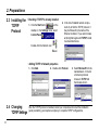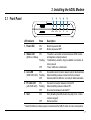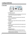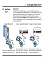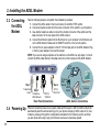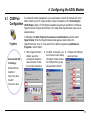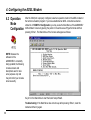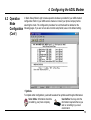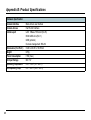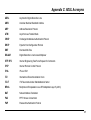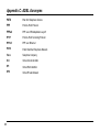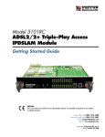
1
AAM6000EV ADSL Modem
User's Manual
Copyright Information
Copyright © 2000 ASUSTeK Computer Inc.
All rights reserved. No part of this publication may be reproduced, transmitted, transcribed, stored in a retrieval
system, or translated into any language or computer language, in any form or by any means, electronic, mechanical,
magnetic, optical, chemical, manual or otherwise, without the prior written consent of ASUSTeK Computer Inc.
Disclaimer
ASUSTeK Computer Inc. makes no representations or warranties with respect to the contents hereof and specifically
disclaims any implied warranties of merchantability or fitness for any particular purpose. Furthermore, ASUSTeK
Computer Inc. reserves the right to revise this publication and to make changes from time to time in the content
hereof without obligation to notify any person of such revisions or changes.
Trademarks
Products and corporate names appearing in this manual may or may not be registered trademarks or copyrights of
their respective companies, and are used only for identification or explanation and to the owners’ benefit, without
intent to infringe.
2
Product Name:
Manual Revision:
AAM6000EV ADSL Modem
1.00 E585
Release Date:
August 2000
Contents
1. Introduction
1.1 Overview ............................................................ 4
1.2 Features ............................................................. 4
2. Preparations
2.1
2.2
2.3
2.4
System Requirements .......................................
Installing a Network Card ...................................
Installing the TCP/IP Protocol ............................
Changing TCP/IP Settings .................................
5. Software Upgrade
5.1 System Update Procedure ............................... 22
5
5
6
6
3. Installing the ADSL Modem
3.1
3.2
3.3
3.4
4.2.8 PPTP Access Concentrator <PAC> ............ 21
4.3 Load Factory Default ....................................... 21
Front Panel ........................................................ 7
Rear Panel ......................................................... 8
Connecting the ADSL Modem ......................... 10
Powering Up .................................................... 10
4. Configuring the ADSL Modem
4.1 COM Port Configuration ................................... 11
4.2 Operation Mode Configuration ......................... 12
4.2.1 MPoA/Bridged <RFC-1483> ...................... 14
4.2.2 MPoA/Routed <RFC-1483> ....................... 15
4.2.3 IPoA <RFC-1577> ...................................... 16
4.2.4 PPPoA/Bridged <RFC-2364> ..................... 17
4.2.5 PPPoA/Routed <RFC-2364> ..................... 18
4.2.6 PPPoE <RFC-2516> .................................. 19
4.2.7 PPPoE Relay <RFC-2516> ........................ 20
Appendix A: Product Certifications
FCC ......................................................................... 26
UL ............................................................................ 26
CE ............................................................................ 26
Appendix B: Product Specifications
ADSL Specifications ................................................
ATM Specifications ..................................................
Basic Protocol and RFC ..........................................
Routing Function ......................................................
Hardware Specification ............................................
Appendix C: ADSL Acronyms
27
27
28
29
30
31
3
1. Introduction
1.1 Overview
Thank you for purchasing the ASUS AAM6000EV ADSL modem. This ADSL modem delivers
the highest performance in Asymetric Digital Subscriber Line technology, allowing you to
simultaneously enjoy the telephone and Internet service using existing copper phone lines.
Ideal for home and small business users, this easy-to-use communication device offers
reliable connectivity as well as remarkable data transfer rates--up to 8Mbps downstream and
640Kbps upstream. Once the ADSL Modem is powered up, you are always online to enjoy
real-time 3D animation, video conferencing, or perform other data intensive operations.
1.2 Features
Standards Compliance
•
•
•
•
ANSI T1.413 Issue 2 compliant
ITU-T G.992.1 (G.dmt) compliant: up to 8Mbps downstream and 640Kbps upstream data rate
ITU-T G.992.2 (G.lite) compliant: supports splitter-less implementation and up to 1.5Mbps
downstream and 512Kbps upstream data rate
ITU-T G.994.1 (G.hs), G.996.1 (G.test), and G.997.1 (G.ploam) support via software
upgrade as standards approved by ITU-T
Hardware Features
•
•
•
Interoperable with Alcatel, Cisco, Lucent, and other DSLAMs
Supports 8 bits of VPI and 16 bits of VCI address range
Capable of transmitting data up to 19,000 feet
Software Features
•
•
4
Supports RFC 2364 protocol (PPP over ATM), RFC 1483 encapsulation, RFC 2516
protocol (PPP over Ethernet), and RFC 1577 protocol (classical IP over ATM)
Firmware upgrade and configuration restoration over TFTP
2. Preparations
2.1 System
Requirements
Before connecting the ADSL modem to your PC, make sure your system is equipped with an
Ethernet controller and supports the TCP/IP protocol.
2.2 Installing a
Network
Card
If your system does not have an embedded Ethernet controller, you must install a network
interface card as instructed below (assuming that you are using the ASUS PCI-L101 Fast
Ethernet card under the operating system of Windows 98):
1. Install the PCI-L101 card on your
motherboard.
2. Power up your PC and follow the Add
New Hardware Wizard’s instructions to
install the driver. When asked to restart
your computer at the end of the installation, click Yes.
3. After restarting the system, right-click
My Computer on the desktop, select
Properties, click the Device Manager
tab, and then double-click Network
adapters to confirm that the Ethernet
driver is properly installed.
5
2. Preparations
2.3 Installing the
TCP/IP
Protocol
• Checking if TCP/IP is already installed
1. Click the Start button
on the
desktop. In the Settings menu, select
Control Panel
.
Double-click the Network icon
2. In the list of installed network components try to find the TCP/IP protocol. It
may be followed by the name of the
Ethernet controller. If you cannot locate
anything that begins with TCP/IP, install
it as described below.
.
• Adding TCP/IP in Network properties
1. Click Add.
2. Double-click Protocol.
3. Select Microsoft from the
manufacturers. In the list
of network protocols
browse to TCP/IP and
then double-click it.
.
2.4 Changing
TCP/IP Settings
6
After the TCP/IP protocol is installed, restart your computer and consult the installation
guide provided by your telephone company to complete TCP/IP configurations.
3. Installing the ADSL Modem
3.1 Front Panel
1
2
POWER
STATUS
3
4
5
LINE
PC
TEST
LED Indicator
1. Power LED
State
Description
ON
OFF
Modem is powered ON
Modem is powered OFF
2. Status LED
ON
OFF
“Showtime”–successful connection between ADSL modem
and telephone company’s network
“Handshaking”–modem is trying to establish a connection to
telco’s network
“Down”–ADSL line is inactivated
ON
Flashing
OFF
Successful connection to telco’s network; ready for data transmission
Data transmitting between modem and telco’s network
Disconnected from ADSL line; not ready for data transmission
ON
Flashing
OFF
Successful connection between LAN and PC
Data transmitting between LAN and PC
No connection between LAN and PC*
ON
Error (Resetting the ADSL modem may help; if not, contact
customer support)
Normal operation
(ADSL Line Status)
Flashing
3. Line LED
(WAN Traffic LED)
4. PC Link LED
(LAN Traffic LED)
5. Test
OFF
* Check if the Ethernet cable is properly connected and the HUB-PC switch is in the correct position.
7
3. Installing the ADSL Modem
3.2 Rear Panel
1
2
3
4
5
6
7
Console
Reset
USB
10/100-BaseT
HUB
DC+5V/2A
Line
Phone
PC
1. DC +5V/2A Power Input Jack
The provided power adapter converts AC power to DC power for use with this jack. Power
supplied through this jack will supply power to the ADSL Modem.
2. Line Connector
The RJ-11 connector allows ADSL data communication between the modem and the
PSTN through a twisted-pair phone wire.
3. Console Port
The 9-pin D-sub serial port supports the RS-232 terminal interface for advanced ADSL
modem management.
4. Reset Switch
The reset button, when pressed, resets the modem without the need to unplug the power cord.
5. USB Port (optional)
The optional USB port allows the modem to be connected to your computer through the
USB interface.
6. 10/100-BaseT Ethernet Port
The RJ-45 Ethernet port supports 10Base-T networks. (100Base-TX networks will be
supported in the near future.) This port allows your PC or Ethernet hub to be connected to
the ADSL Modem through a Cat. 5 Ethernet cable.
8
3. Installing the ADSL Modem
7. HUB-PC Switch
3.2 Rear Panel
(Cont’)
The HUB-PC switch controls the crossover function. Modem-to-PC connection must
contain crossovers. When connecting the modem to a PC, leaving the switch on the default
position PC allows you to implement crossover cabling without using a crossover cable.
When connecting the modem to an Ethernet hub’s RJ-45 downlink port, use a pen or
screwdriver to slide the switch to HUB and implement straight-through cabling. If you run
out of the hub’s downlink ports and connect the modem to the uplink port, you must slide the
switch to the position of PC.
Example 1. Modem to PC
Example 2. Modem to Hub (Downlink)
UPLINK
HUB
HUB
1
2
3
4
5
6
7
8
PC
Example 3. Modem to Hub (Uplink)
UPLINK
HUB
1
2
3
4
5
6
7
8
PC
PC
When using a PC with the modem, adjust
the HUB-PC switch to the position of PC.
When connecting the modem to an
Ethernet hub’s downlink port, adjust the
HUB-PC switch to the position of HUB.
When connecting the modem to an
Ethernet hub’s uplink port, adjust the HUBPC switch to the position of PC.
9
3. Installing the ADSL Modem
Take the following steps to accomplish the installation procedure:
1. Connect the ADSL cable to the line connector of an ADSL POTS splitter.
2. Connect a telephone cable from the phone connector of the splitter to your telephone.
3. Use another telephone cable to connect the modem connector of the splitter and the
Line connector on the rear panel of the ADSL modem.
4. Connect the Ethernet cable from the RJ-45 port on your computer to the Ethernet port
on the ADSL Modem. Make sure the HUB-PC switch is in the correct position.
5. Connect the AC power adapter to the DC +5V/2A input jack on the ADSL Modem. Plug
in the AC power adapter to an electrical outlet.
NOTE: If you are not using a telephone or fax machine on the ADSL line, skip steps 1 to 3 and
connect the ADSL cable directly to the Line connector on the rear panel of the ADSL Modem.
3.3 Connecting
the ADSL
Modem
ADSL
Modem
Step 5
To Electrical
Outlet
Step 4
Step 3
To Splitter or
ADSL Network
To PC’s
COM Port
Rear Panel Connections
3.4 Powering Up
10
To PC’s
RJ-45 Port
To Telco’s
ADSL
Network
ADSL
Splitter
Computer
Phone/Fax
ADSL Service Connections
When all connections have been properly made and the power is ON, the ADSL modem will
automatically start the self-test and log on to your phone company’s ADSL network. For new
modems, please go through the configuration as detailed in the following section, and then
you are all set and ready to enjoy the Internet services at a marvelous speed!
4. Configuring the ADSL Modem
4.1 COM Port
Configuration
For advanced modem management, use a serial cable to connect the Console port on the
ADSL modem to your PC’s empty COM port. (See the illustration in 3.3 Connecting the
ADSL Modem.) Open a VT100 terminal emulation program such as NetTerm or Windows’
HyperTerminal to configure the COM port. (The setup under HyperTerminal is given as an
example below.)
In Windows, click Start, Programs, Accessories, Communications, and then select
HyperTerminaI. When the HyperTerminal window appears, double click on the
HyperTerminal icon to run it. If you cannot find it, add the program using Add/Remove
Programs in Control Panel.
Recommended COM
Port Settings:
Bit Rate: 9600 bps
1. When HyperTerminal is
started, you will be
prompted to establish a
new connection. Follow
the onscreen instruction.
2. For ADSL connections, you 3. Configure the COM port
do not have to enter dial-up
as shown below.
information. Simply choose
the COM port that you are
using and then click OK.
Data Bits: 8
Parity Check: None
Stop Bit: 1
Flow Control: None
11
4. Configuring the ADSL Modem
4.2 Operation
Mode
Configuration
After the COM port is properly configured, select an operation mode for the ADSL modem in
the terminal emulation program. If you have established an ADSL connection as demonstrated in 4.1 COM Port Configuration, you may evoke the Main Menu of the AAM6000EV
ADSL Modem Console by placing the pointer in the white area of HyperTerminal and then
pressing <Enter>. The Main Menu of the Console will appear as follows:
NOTE: Because the
software for the
AAM6000EV is constantly
being updated, the following
console screens and
descriptions are for reference purposes only and
may not reflect your console
screens exactly.
Key in 3 in the Main Menu to start the Quick Setup Wizard.
Troubleshooting: If the Main Menu does not show up after pressing <Enter>, reset the
modem and then try again.
12
4. Configuring the ADSL Modem
4.2 Operation
Mode
Configuration
(Cont’)
In Quick Setup Wizard, eight console operation modes are provided for your ADSL modem
configuration. Refer to your ADSL service manual or consult your phone company before
selecting the mode. The configuration procedure for each mode will be detailed on the
following pages. If you are not sure about certain setup fields, leave on the default setting.
• Symbols
To complete certain configurations, you should be aware of two symbols used throughout this manual.
Telco Define: Information should be
provided by your phone company.
User Define: You may enter the
information required either as you
wish or according to your own
environment.
13
4. Configuring the ADSL Modem
4.2.1 MPoA/Bridged
<RFC-1483>
Enter 1 in the Quick Setup Wizard to set up MPoA/Bridged mode.
MPoA/Bridged mode
complies with IETF RFC1483 Multiprotocol Encapsulation over ATM Adaptation Layer 5. In this mode,
the modem acts as a
bridging device.
Step 1
Step 2
Step 3
Step 4
14
Step 5
4. Configuring the ADSL Modem
4.2.2 MPoA/Routed
<RFC-1483>
Enter 2 in the Quick Setup Wizard to set up MPoA/Routed mode.
MPoA/Routed mode
complies with IETF RFC1483 Multiprotocol Encapsulation over ATM Adaptation Layer 5. In this mode,
the modem acts as a
routing device, and, when
configured to, implements a
NAT function for users to
assign virtual IPs to their
PCs.
Step 1
Step 2
Step 3
Step 5
Step 4
Step 6
Step 7
Step 8
Step 9
Step 10
Note for Step 8: The subnet address must consist of hexadecimal numbers.
15
4. Configuring the ADSL Modem
4.2.3 IPoA
<RFC-1577>
Enter 3 in the Quick Setup Wizard to set up IPoA mode.
IPoA mode complies with
the IETF RFC-1577 IP over
ATM. In this mode, the
modem acts as a routing
device and, when configured to, implements a NAT
function for PCs to share a
single real IP.
Step 1
Step 2
Step 3
Step 5
Step 4
Step 6
Step 7
Step 8
Step 9
Step 10
Step 11
Note for Step 7: The subnet address must consist of hexadecimal numbers.
16
4. Configuring the ADSL Modem
4.2.4 PPPoA/Bridged
<RFC-2364>
PPPoA/Bridged mode
complies with IETF RFC2364 PPP over ATM. In this
mode, the modem acts as a
bridging device, and allows
users to enter their user
names and passwords to
log on to the server’s
network. This mode also
supports authentication
protocols (PAP, CHAP) and
different IP control protocols
(IPCP, DHCP).
Enter 4 in the Quick Setup Wizard to set up PPPoA/Bridged mode.
Step 1
Step 2
Step 3
Step 4
Step 5
Step 6
Step 7
Step 8
Step 9
17
4. Configuring the ADSL Modem
4.2.6 PPPoA/Routed
<RFC-2364>
PPPoA/Routed mode
complies with IETF RFC2364 PPP over ATM. In this
mode, the modem acts as a
routing device, and allows
users to enter their user
names and passwords to
log on to the server’s
network. This mode also
supports authentication
protocols (PAP, CHAP),
different IP control protocols
(IPCP, DHCP), and a NAT
function for PCs to share a
real IP.
Enter 5 in the Quick Setup Wizard to set up PPPoA/Routed mode.
Step 1
Step 2
Step 3
Step 4
Step 5
Step 6
Step 7
Step 8
Step 9
Step 10
Step 11
Step 12
Step 13
Note for Step 4: The subnet address must consist of hexadecimal numbers.
18
4. Configuring the ADSL Modem
4.2.7 PPPoE
<RFC-2516>
Enter 6 in the Quick Setup Wizard to set up PPPoE mode.
PPPoE mode complies with
IETF RFC-2516 PPP over
Ethernet. In this mode, the
modem allows users to
enter their user names and
passwords to log on to the
server’s network. This mode
also supports authentication
protocols (PAP, CHAP),
different IP control protocols
(IPCP, DHCP), and a NAT
function for PCs to share a
real IP.
Step 1
Step 2
Step 3
Step 4
Step 5
Step 6
Step 7
Step 8
Step 9
Step 10
Step 11
Step 12
Step 13
Step 14
Step 15
Note for Step 4: The subnet address must consist of hexadecimal numbers.
19
4. Configuring the ADSL Modem
4.2.8 PPPoE Relay
<RFC-2516>
Enter 7 in the Quick Setup Wizard to set up PPPoE Relay mode.
PPPoE mode complies with
IETF RFC-2516 PPP over
Ethernet. In this mode, the
modem allows users to use
other software solutions to
implement the PPPoE client
function.
Step 1
Step 2
Step 3
Step 4
Step 5
20
4. Configuring the ADSL Modem
4.2.9 PPTP Access
Concentrator <PAC>
Enter 8 in the Quick Setup Wizard to set up PPTP Access Concentrator mode.
PPTP Access Concentrator
mode supports Virtual
Private Network (VPN) with
the latest PPTP technology.
It allows remote users to log
on to a private network
through the Internet or other
networks.
Step 1
Step 2
Step 3
Step 4
Step 5
4.3 Load Factory
Default
Enter 5 in
the Main
Menu.
Step 1
Enter 2 in
the System
Maintenance
Menu.
Step 2
21
5. Software Upgrade
5.1 System
Update
Procedure
1. Download an updated software image file from the Internet (see ASUS Contact Information on the inside of the back cover for details) and save it to your hard drive.
2. Make sure the modem is connected to your PC through the Ethernet interface and the
Console port on the modem is connected to your PC’s COM port.
3. Run a terminal emulation program such as HyperTerminal.
4. Run a BOOTP server program such as Weird Solutions’ BOOTP Server95, which works on
Windows 95/98 as well as Windows NT. Configure your BOOTP server as shown below.
Enter the MAC address
labeled on the back of your
ADSL modem.
Select Boot file and
IP address from
Avalable options.
Click Edit to enter the IP
address of your computer.
Click Close when you are done.
22
5. Software Upgrade
5.1 System
Update
Procedure
(Cont’)
5. Run a TFTP server program such as Cisco TFTP Server.
Browse to the location of
the updated FLASH file you
saved on your computer.
23
5. Software Upgrade
5.1 System
Update
Procedure
(Cont’)
6. Press the reset button on the modem and at the same time press the asterisk key <*> in
your terminal emulation program. When a question appears asking you to “Boot from
Ethernet, USB or Flash”, enter E since the modem is connected to your computer through
the Ethernet interface.
7. The modem will then boot from the Ethernet and automatically start downloading the
software image file from the computer.
24
5. Software Upgrade
5.1 System
Update
Procedure
(Cont’)
8. When the file is successfully downloaded, the main menu of the updated
console will be launched.
9. In Main Menu, enter 5 for System
Maintenance.
10. In System Maintenance Menu, enter 3
for Firmware Update. The software
update is now completed.
NOTE: If Boot ROM update is required as part of the software upgrade, it
will be specified on the ASUS web site where you download the updated
software image. Then please refer to the web site for detailed Boot ROM
update procedures.
25
Appendix A: Product Certifications
FCC (Federal Communications
Commission
Statement)
26
This ASUS AAM6000EV ADSL Modem has been tested and found to comply with the limits
for a class B personal computer and peripherals, pursuant to Part 15 of the FCC Rules.
These limits are designed to provide reasonable protection against harmful interference in a
residential installation. This equipment generates, uses and can radiate radio frequency
energy and, if not installed and used in accordance with the instructions, may cause harmful
interference to radio communications. However, there is no guarantee that interference will
not occur in a particular installation. If this unit does cause harmful interference to radio or
television reception, which can be determined by turning the unit off and on, the user is
encouraged to try to correct the interference by one or more of the following measures:
•
Reorient or relocate the receiving antenna.
•
Increase the separation between the equipment and receiver.
•
Connect the equipment into an outlet on a circuit different from that to which the
receiver is connected.
UL
This product meets all safety requirements per UL-1950 Type 3 standard.
CE
This certificate of conformity is based on an evaluation of the AAM6000EV product that is in
compliance with the Low Voltage Directive 73/23/EEC and the Amendment Directive 93/68/
EEC.
Appendix B: Product Specifications
ADSL Specifications
Line Coding
• Discrete Multi-Tone (DMT)
Standards Compliance
• Full rate ADSL ANSI T1.413 Issue 2
• ITU G.992.1 (G.dmt)
• Splitterless ITU G.992.2 (G.lite)
• Maximum transmission rate: Downstream up to 8Mbps
Upstream up to 800Kbps
Data Rate
Rate Adaption
• Data rate auto-negotiation in 32Kbps increments
ATM Specifications
ATM Adaption Layer
• Supports AAL5
ATM Signaling
• ATM Forum UNI3.0, 3.1, and UNI4.0
VCs
• Supports multiple Permanent Virtual Circuits (PVCs)
Service Class
• CBR, UBR
OAM
• ITU-T I.610 OAM Principles and Functions (including F4/F5) loop
27
Appendix B: Product Specifications
Basic Protocol & RFC
RFC 1483
Multiple protocol encapsulation over AAL5
• Supports Logical Link Control (LLC) encapsulation
• Supports VC-based multiplexing
RFC 2364
PPP over AAL5
• Supports LLC encapsulation
• Supports VC-based multiplexing
• Supports VPN
28
RFC 2516
PPP over Ethernet
• Supports VPN
RFC 1577
Classical IP and ARP over ATM
RFC 1661
PPP Link Control Protocol (LCP)
RFC 1332
Internet Protocol Control Protocol (IPCP)
RFC 1334
PPP Authentication Protocol (PAP)
RFC 1994
PPP Challenge Handshake Authentication Protocol (CHAP)
RFC 792
Internet Control Message Protocol (ICMP)
802.1 d
Spanning-tree bridge
Appendix B: Product Specifications
Routing Function
RFC 1058, 1723
Routing Information Protocol (RIP, RIPv2)
• Packet Filtering for the In/Out Packets
RFC 1631
Network Address Translation (NAT)
• Supports FTP, mail, Telnet, HTTP
• Supports Netmeeting
RFC 2131
Dynamic Host Configuration Protocol (DHCP)
• Supports DHCP server and client
VPN
Virtual Private Networks
• Supports Point-to-Point Tunneling Protocol (PPTP)
29
Appendix B: Product Specifications
Hardware Specification
30
Console Interface
Console Access
• Menu-driven user interface
• Via RS-232 interface
Interface port
Dimensions (H x W x D )
Weight
Power Consumption
• LAN: 10Base-T Ethernet (RJ-45)
• WAN: ADSL line (RJ-11)
• USB (optional)
• Console management: RS-232
• 34.60 x 202.95 x 182.50mm
• 470g
• 10W (max.)
DC Input Voltage
Operating Temperature
Non-operating Temp.
• DC +5V
• 32° ~ 104° F (0° ~ 40° C)
• -4° ~ 149° F (-20° ~ 65° C)
Appendix C: ADSL Acronyms
ADSL
Asymmetric Digital Subscriber Line
ANSI
American National Standards Institute
ARP
Address Resolution Protocol
ATM
Asynchronous Transfer Mode
CHAP
Challenge-Handshake Authentication Protocol
DHCP
Dynamic Host Configuration Protocol
DMT
Discrete Multi-Tone
DSLAM
Digital Subscriber Line Access Multiplexer
IETF RFC
Internet Engineering Task Force Request for Comments
IPCP
Internet Protocol Control Protocol
IPoA
IP over ATM
ITU
International Telecommunication Union
ITU-T
ITU Telecommunication Standardization Sector
MPoA
Multiprotocol Encapsulation over ATM Adaptation Layer 5 (AAL5)
NAT
Network Address Translation
PAC
PPTP Access Concentrator
PAP
Password Authentication Protocol
31
Appendix C: ADSL Acronyms
32
POTS
Plain Old Telephone Service
PPP
Point-to-Point Protocol
PPPoA
PPP over ATM Adaptation Layer 5
PPTP
Point-to-Point Tunneling Protocol
PPPoE
PPP over Ethernet
PSTN
Public Switched Telephone Network
Telco
Telephone Company
VCI
Virtual Circuit Identifier
VPI
Virtual Path Identifier
VPN
Virtual Private Network