1
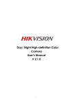
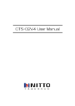
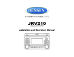
VR182
MOBILE AUDIO SYSTEM
Installation and Operation Manual
VR182
SAFETY INFORMATION
When Driving
Keep the volume level Iow enough to be aware of the road and traffic conditions.
Protect from Water
Do not expose the product to water, as this can cause electrical shorts, fire or other damage.
Protect from High Temperatures
Exposure to direct sunlight for an extended period of time can produce very high temperatures
inside your vehicle. Give the interior a chance to cool down before starting playback.
Do not mount radio within close proximity of engine compartment.
Use the Proper Power Supply
This product is designed to operate with a 12 volt DC negative ground battery system.
Protect the Disc Mechanism
Avoid inserting any foreign objects into the disc slot. Misuse may cause malfunction or
permanent damage due to the precise mechanism of this unit.
CAUTION:
THIS MOBILE CD PLAYER IS A CLASS I LASER PRODUCT. THIS UNIT USES A VISIBLE/
INVISIBLE LASER BEAM WHICH COULD CAUSE HAZARDOUS RADIATION IF EXPOSED
DIRECTLY. BE SURE TO OPERATE THE MOBILE CD PLAYER AS INSTRUCTED.
USE OF CONTROLS OR ADJUSTMENTS OR PERFORMANCE OR PROCEDURES OTHER
THAN THOSE SPECIFIED HEREIN MAY RESULT IN HAZARDOUS RADIATION
EXPOSURE.
DO NOT OPEN COVERS AND DO NOT REPAIR BY YOURSELF. PLEASE REFER
SERVICING TO A QUALIFIED TECHNICIAN.
WARNING:
•
•
•
TO REDUCE THE RISK OF FIRE OR ELECTRIC SHOCK, DO NOT EXPOSE THIS
EQUIPMENT TO WATER.
TO REDUCE THE RISK OF FIRE OR ELECTRIC SHOCK AND INTERFERENCE, USE
ONLY THE RECOMMENDED ACCESSORIES.
THIS DEVICE IS INTENDED FOR CONTINUOUS OPERATION.
2
VR182
DISC NOTES
Depending on the recording status, conditions of the disc, and the equipment used for
recording, some CD-Rs/CD-RWs may not play on this unit. For more reliable playback, please
adhere to the following recommendations:
•
•
•
NOTE: A disc may become scratched (although not enough to make it unusable)
depending on how you handle it and other conditions in the usage environment. These
scratches are not an indication of a problem with the player.
Use CD-RWs with speed 1x to 4x and write with speed 1x to 2x.
Use CD-Rs with speed 1x to 8x and write with speed 1x to 2x.
Do not play a CD-RW which has been written more than 5 times.
Compatible Disc Types
Table 1: General Disc Information
Disc Type
Diameter/
Playable Sides
Logo
Audio CD
12 cm single side
RECORDABLE
Playback Time
74 minutes
REWRITABLE
NOTE: CD-R and CD-RW discs will not play unless the recording session is closed and
the CD is finalized.
Disc Maintenance
•
A dirty or defective disc may cause sound dropouts while playing. Before playing, wipe
the disc using a clean cloth, working from the center hole towards the outside edge.
Never use benzene, thinners, cleaning fluids, anti-static liquids or any other solvent.
Insert label
side up.
•
•
•
Do not bend.
Never touch
the under side
of the disc.
Wipe clean from
the center to the
edge.
Be sure to use only round CDs for this unit and do not use any special shape CDs. Use of
special shape CDs may cause the unit to malfunction.
Do not stick paper or tape on the disc. Do not use CDs with labels or stickers attached or
that have sticky residue from removed stickers.
Do not expose discs to direct sunlight or heat sources such as hot air-ducts, or leave them
in a vehicle parked in direct sunlight where there can be a considerable rise in
temperature inside the vehicle.
3
VR182
INSTALLATION
Before You Begin
1.
Disconnect Battery
Before you begin, always disconnect the battery negative terminal.
2.
Remove Transport Screws and discard.
MOUNTING SLEEVE
Important Notes
•
•
•
•
•
•
Before final installation, test the wiring connections to make sure the unit is connected
properly and the system works.
Use only the parts included with the unit to ensure proper installation. The use of
unauthorized parts can cause malfunctions.
Consult with your nearest dealer if installation requires the drilling of holes or other
modifications to your vehicle.
Install the unit where it does not interfere with driving and cannot injure passengers if
there is a sudden or emergency stop.
If the installation angle exceeds 30º from horizontal, the unit might not give optimum
performance.
Avoid installing the unit where it will be subject to high temperatures from direct sunlight,
hot air, or from a heater, or where it would be subject to excessive dust, dirt or vibration.
REMOVAL KEY
2.
3.
DIN Front Mount
This unit can be installed in a dashboard with an opening of the following dimensions:
Check the dashboard opening size by sliding the mounting sleeve into it. If the opening is
not large enough, carefully cut or file as necessary until the sleeve easily slides into the
opening. Do not force the sleeve into the opening or cause it to bend or bow. Check that
there will be sufficient space behind the dashboard for the radio chassis.
Locate the series of bend tabs along the top, bottom and sides of the mounting sleeve.
With the sleeve fully inserted into the dashboard opening, bend as many of the tabs
outward as necessary to firmly secure the sleeve to the dashboard.
DASHBOARD
TABS
93mm
SCREWDRIVER
182.6mm
1.
MOUNTING SLEEVE
4.
Slide the mounting sleeve off of the chassis if it has not already been removed. If it is
locked into position, use the removal keys (supplied) to disengage it. Insert the keys
through the holes in the front panel as far as they will go, and then slide the sleeve off the
back of the unit.
5.
6.
7.
8.
4
Place the radio in front of the dashboard opening so the wiring can be brought through the
mounting sleeve.
Follow the wiring diagram carefully and make certain all connections are secure and
insulated with crimp connectors or electrical tape to ensure proper operation.
After completing the wiring connections, reconnect battery and turn the unit on to confirm
operation (vehicle ignition switch must be on). If the unit does not operate, recheck all
wiring until the problem is corrected. Once proper operation is achieved, turn the ignition
switch off and proceed with final mounting of the chassis.
Carefully slide the radio into the mounting sleeve making sure it is right-side-up until it is
fully seated and the spring clips lock it into place.
Test radio operation by referring to the operating instructions for the unit.
VR182
Ford Vehicle Mount
1.
Remove the mounting sleeve (see step 1 of “DIN Front Mount” on page 4). The mounting
sleeve is not used in this application.
2.
Use the supplied mounting screw and the rear installation bracket to secure the unit in
place.
REMOVAL KEYS
REAR INSTALLATION
BRACKET
MOUNTING
SCREW
3.
4.
5.
6.
7.
Place the radio in front of the dashboard opening so the wiring can be brought through the
mounting sleeve.
Follow the wiring diagram carefully and make certain all connections are secure and
insulated with crimp connectors or electrical tape to ensure proper operation.
After completing the wiring connections, reconnect battery and turn the unit on to confirm
operation (vehicle ignition switch must be on). If the unit does not operate, recheck all
wiring until the problem is corrected. Once proper operation is achieved, turn the ignition
switch off.
Carefully slide the radio onto the guide rail inside the vehicle dash until it is fully seated
and the spring clips lock into place.
Test radio operation by referring to the operation section for the unit.
Removing the Unit
To remove the radio after installation:
1.
Make sure the ignition is turned off, and then disconnect the cable from the vehicle’s battery negative (-) terminal.
2.
Insert the removal keys straight into the holes on the front of the unit, as far as they will
go.
Pull the radio straight out.
3.
5
VR182
WIRING
SIRIUS Connector
CD Changer Connector
Antenna Connection
(BLUE WIRE)
RED
Aux-In RCA
Connections
A
(YELLOW WIRE)
WHITE
(RED WIRE)
(YELLOW WIRE)
RED
Aux-Out RCA
Connections
0.5A FUSE
A
15A FUSE
(GRAY WIRE)
A-A
WHITE
Chassis Ground
Connect to ground terminal or clean
unpainted metal part of chassis.
(BLACK WIRE)
IR Remote Connector
(WHITE WIRE)
iPOD Connector
Power Antenna
Connect to power antenna
or amplifier. If not used,
tape bare end of wire.
+12V Battery/Constant
Connect to battery or 12 volt power source
that is always live. The radio will not work if
this wire is not connected.
12V Ignition/Switched
Connect to existing radio wire or radio fuse.
6
VR182
BASIC OPERATION
2.
3.
4.
5.
Rotate the VOLUME control (1) within 5 seconds to adjust the hours.
Press the DISP button again and the minutes will flash.
Rotate the VOLUME control within 5 seconds to adjust the minutes.
Press DISP again to exit time set mode. After 5 seconds, time set mode will exit
automatically.
NOTE: If the time mode is set to “12 HOUR” in the setup menu, continue turning the
VOLUME control to change between AM (A) and PM (P).
NOTE: If “P-CLOCK ON” is selected in the setup menu, the clock will be displayed in the
center of the LCD in large characters when the unit is turned off while the ACC is on.
Reset
Use a ball point pin or thin metal object to press the RESET button (18). The unit will return to
the factory default settings. The reset button should be activated for the following reasons:
•
•
•
initial installation of the unit when all wiring is completed
function buttons do not operate
error symbol on the display
To recover factory default settings, press and hold the MODE button (4) for more than 3
seconds. The LCD will display “EEP-INIT” and all settings will return to the original factory
values.
Power On/Off
Audio Menu
Press any button (except the eject button (23)) to turn the unit ON. Press the VOLUME/ON/
OFF button (1) to turn the unit OFF.
Press the AUDIO/MENU button (3) on the control panel to access the Audio Menu. You can
navigate through the Audio Menu items by pressing the AUDIO/MENU button repeatedly.
Once the desired menu item appears on the display, adjust that option by turning the VOLUME
control (1) within 5 seconds. The unit will automatically exit the Audio Menu after five seconds
of inactivity. The following menu items can be adjusted.
Volume Control
To increase the volume, rotate the volume control (1) clockwise.
To decrease the volume, rotate the volume control counter clockwise.
Bass Level
Mute
Use the volume control to adjust the Bass level range from “-6” to “+6”.
Press the MUTE button (26) on the control panel to mute the audio output. “Mute” will appear
on the LCD display. Press MUTE again to restore the audio output to the previous level.
Treble Level
Use the volume control to adjust the Treble level range from “-6” to “+6”.
Mode
Balance
Press the MODE button (4) on the control panel to select a different mode of operation, as
indicated on the display panel. Available modes include TUNER, CD, SIRIUS, IPOD, CDC and
AUX IN (optional Auxiliary Input).
Use the volume control to adjust the Balance between the left and right speakers from “12L”
(full left) to “12R” (full right).
Fader
NOTE: CDC, IPOD, or SIRIUS mode will be skipped if the module is not installed.
Use the volume control to adjust the Fader between the rear and front speakers from “12R”
(full rear) to “12F” (full front).
Adjusting the Clock (DISP)
Volume Level
The current time is displayed in the lower right hand corner of the LCD display.
Use the volume control to adjust the Volume level from 0 to 46.
To adjust the clock:
1.
Press the DISP button (14) until the hour flashes on the LCD.
7
VR182
System Menu
1.
Press and hold the MENU/AUDIO button (3) for more than 3 seconds to enter the system
menu.
2.
3.
4.
5.
Rotate the VOLUME control (1) to highlight the desired item.
Press the VOLUME button (1) to select the highlighted item.
Rotate the VOLUME control to select a value.
Press the VOLUME button to return to menu selection mode.
The following feature functions can be adjusted:
•
•
•
•
•
•
•
•
BEEP (ON/OFF): Turn the audible beep ON/OFF (heard when functions/buttons are
selected).
P-VOLUME (00 – 46): Select an automatic turn-on volume.
AREA (EURO/USA)
P-CLOCK (ON/OFF): Choose “ON” to display the clock in large format when the radio is
turned off while ACC is on.
CLOCK (12/24 HOUR)
CONTRAST (-6 – +6)
BRIGHTNESS (0 – 7)
AUTO IPOD (ON/OFF): Choose “ON” to automatically switch to iPod mode when an iPod
is connected.
Default values: BEEP ON, P-VOLUME 12, USA, CLOCK ON, 12 HOUR, CONTRAST 0,
BRIGHTNESS 4, AUTO IPOD ON.
Equalizer
Press the EQ/LOUD button (11) to turn the equalization function on/off.
Auxiliary Input
To access an auxiliary device:
1.
Connect the portable audio player to the AUX in on the front panel (21) or to the AUX IN
cables on the back of the radio.
2.
3.
Press the MODE button to select Aux In mode.
Press MODE again to cancel Aux In mode and return to the previous mode.
NOTE: The front AUX input overrides the rear Auxiliary Input.
Scroll
When in Sirius Satellite Radio or iPod mode, press the SCROLL button (14) to view the entire
program information.
Remote Sensor
Point the remote control handset (sold separately) at the remote sensor IR (2) and press the
function keys on the handset to control the system.
8
VR182
TUNER OPERATION
replace any stations already stored in that band. After stations have been stored, the radio will
enter Preset Scan and preview each stored station.
Preset Scan
Select a band (if needed). Press AS/PS (15) to scan stations stored in the current band. The
unit will pause for ten seconds at each preset station. Press AS/PS again to stop scanning
when the desired station is reached.
Weather Band Selection
In any mode, press the WB button (17) to access the weather band (NOAA seven frequency
broadcast). In weather band mode, the tuner will automatically seek the active weather band
automatically and stop.
Rotate the TUNE ADJUST knob (22) clockwise or counter-clockwise to choose a channel from
CH1 – CH7. You can also press the six preset buttons (27) to select CH1 – CH6 directly.
Press the SEEK < / > buttons (20/19) to seek the stations down/up.
Press the BAND (16) or MODE (4) button to exit weather band mode.
NOTE: The weather band channel frequency is fixed in preset memory and cannot be
changed.
RDBS Operation
While in FM Radio mode, press the TA button (12) to start search of a Traffic Announcement in
your area. If no TA information is being broadcast, the radio will display “NO TA” and return to
the previously tuned station.
Select a Band
Press the BAND button (16) on the control panel to change between two FM bands and one
AM band. In Sirius Satellite Radio, WB, CD, CDC, AUX IN or IPOD mode, press the BAND
button to automatically switch to radio mode.
In any mode, press the TA button to access Traffic Announcement mode. If a TA is being
broadcast, playback of the current mode will be interrupted and the radio will switch to the FM
station issuing the TA. Press the TA button again to exit TA mode.
Tuning
In FM radio mode, press the PTY button (13) to list the following search options: ANY / News /
Information / Sports / Talk / Rock / Classic Rock / Adult Hits / Soft Rock / Top 40 / Country /
Oldies / Soft / Nostalgia / Jazz / Classical / Rhythm and Blues / Soft R&B / Language /
Religious Music / Religious Talk / Personality / Public / College / Weather / Emergency Test /
Emergency.
Rotate the TUNE ADJUST knob (22) clockwise or counter-clockwise to tune up or down in one
step increments. Press the SEEK > (19) or SEEK < button (20) to seek the next strong station.
Press and hold a SEEK button (19/20) to seek the stations up/down step by step.
Preset Stations
Use the TUNE ADJUST knob (22) to select an item from the list, then press SEEK < / > (20/
19) to search the corresponding program. “PTY SEARCH' will be displayed in the upper right
corner of the LCD. If a corresponding program is found, the unit will play the program. If there
is no corresponding program, “PTY NOT FOUND” will be displayed on the LCD.
Six numbered preset buttons store and recall stations for each band (FM1, FM2, AM).
Store a Station
Tune radio to desired station. Press and hold a preset button (27) for three seconds. A beep
tone will confirm the stored station and the preset number will appear in the display.
Stereo (ST)
The unit will automatically pick up an FM stereo signal, when available. When in stereo mode,
the “ST” icon appears in the display. When no stereo signal is available, the unit will
automatically revert to mono operation, and no icon will be displayed.
Recall a Station
Select a band (if needed). Press a preset button (27) to select the corresponding stored
station.
Automatic Store / Preset Scan (AS/PS)
Automatic Store
Select a band (if needed). Press and hold the AS/PS (15) button for more than three seconds
to automatically select six strong stations and store them in the current band. New stations
9
VR182
CD/MP3/WMA OPERATION
Repeat Play
Press the RPT button (5) during disc play to repeat play the current track. Press RPT again to
stop repeat play
Random Play
Press the SHUF button (7) on the control panel during disc play to play all tracks on a CD in
random, shuffled order. “SHUFFLE” will display in the upper right corner. Press SHUF again to
stop random play.
Selecting MP3/WMA Tracks
The AS/PS button (15) functions as the Digital Audio Mode selection button during MP3/WMA
operation.
Direct Track Search
1.
Press the AS/PS button (15) once to search for a track name directly. The current track
number will be displayed: “DIRECT 002".
2.
3.
Rotate the VOLUME control (1) to change the track number.
Press the ENTER button (22) to search the track.
Directory/File Name Search
Inserting and Ejecting a Disc
Insert a disc, label-side up, into the disc slot (24) with the unit turned on. The unit will
automatically draw the disc in and play the first track on the disc.
Press the eject button (23) to stop disc play and eject the disc. The unit does not have to be
turned on to eject the disc.
Controlling Disc Playback
Selecting Tracks
Press the SEEK > (19) or SEEK < button (20) to advance to the next track on the CD. The
selected track number will appear on the display. Press and hold the SEEK > (19) or SEEK <
button (20) to fast forward or fast reverse through the disc. CD play starts when the button is
released.
For an MP3/WMA disc, press the DISC/DIR UP or DN button (10/9) to skip to the following/
previous folder.
Play/Pause Disc Playback
Press the >/|| button (26) to suspend disc play. Press the >/|| button again to resume disc Play.
Previewing Tracks
Press the SCAN button (6) on the control panel to play the first 10 seconds of each track
sequentially. Press SCAN again to stop Intro Scan and resume normal play at the current
track.
10
1.
Press the AS/PS (15) button two times to search for a Directory or File Name.
2.
3.
4.
Use the VOLUME control (1) to input numbers 0 – 9 and characters A – Z.
Press the AUDIO button (3) to confirm entry of each character.
Press the ENTER button (22) to start the title search. The unit will search files and
directories containing the specified characters.
VR182
SIRIUS RADIO OPERATION
tune to that channel. While viewing a category list, press the DISP button to change display
information between Channel Name, Artist, or Song Title.
Storing Preset Channels
The preset buttons (27) can be used to store 6 channels per band (SIR1, SIR2 and SIR3),
allowing convenient access to your favorite channels.
Programming Channels
1.
Select the channel you want to store in memory.
2.
Press and hold a preset button (27) until the corresponding preset button number
appears.
Repeat steps 1 and 2 to program additional channels.
3.
Recalling a Preset Channel
Press one of the six preset buttons (27) within a selected band to tune a preset channel
directly.
Channel Preset Scan
Press the AS/PS button (15) to preview each stored preset channel in SIR1, SIR2 and SIR3 for
10 seconds.
Press the AS/PS button again to stop scanning and play the current channel.
Direct Tune Mode
Switching to SIRIUS Mode
1.
Press and hold the S-MOD button (22) to switch to Direct Tune/Skip Channel mode. After
accessing Direct mode, “DIRECT _ _ _” appears on the display.
Press the MODE button (4) to change the mode to Sirius Satellite Radio mode.
2.
Use the TUNE ADJUST UP/DN knob (22) to select a number for the hundreds digit
position.
Press the ENTER button (22) to confirm entry of the hundreds digit. The tens digit will
flash on/off.
Use the TUNE ADJUST UP/DN knob to select a number for the tens digit position.
Press the ENTER button again to confirm entry of the tens digit. The ones digit will flash
on/off.
Use the TUNE ADJUST UP/DN knob to select a number for the ones digit position.
Press the ENTER button to tune to the selected channel.
Activating Sirius Satellite Radio
3.
In Sirius mode, press and hold the S-MOD button (22) to select DIRECT mode. The LCD will
display “DIRECT _ _ _” upon entry. Use the TUNE ADJUST UP/DN knob (22) to select “0” and
then press the ENTER button (22) to input the number. Continue for remaining digits. Enter
“000” to display the 12 digit Sirius ID.
4.
5.
Selecting a Band
6.
7.
In Sirius mode, press the BAND button (16) to access the Sirius user-preset channel groups in
the following order: SIR1, SIR2, SIR3.
Skip Channel Mode
Tuning a Channel
1.
Press and hold the S-MOD button (22) to switch to Direct Tune/Skip Channel mode.
Rotate the TUNE ADJUST UP/DN knob (22) clockwise to tune up or counter-clockwise to tune
down the available Sirius channels. The channel information display can be changed to
emphasize either Artist or Song Title by pressing the DISP button (14). Press and hold the
DISP button to scroll.
2.
While the display is showing “DIRECT _ _ _”, press the S-MOD button to access Skip
Channel mode.
Use the TUNE ADJUST UP/DN knob (22) to select the channel to be skipped.
Press and hold the ENTER button (22) to skip or release the current channel. (If the
channel was previously skipped, the “SKIP” icon will be displayed.)
Press the S-MOD button (22) to return to normal mode. The unit will automatically return
to normal mode after several seconds of inactivity.
3.
4.
Selecting a Category
5.
Press the CATEGORY < / > buttons (20/19) to view available categories. Each category title
and associated channels will be displayed in increments. While in the category mode, the
individual channels within a category may be accessed by rotating the TUNE ADJUST UP/DN
knob (22). Once a highlighted channel has been selected, press the ENTER button (22) to
11
VR182
IPOD OPERATION
Random Play
During playback, press the SHUF button (7) to play all songs in the current category in random
order. Random play will begin once the current song has finished playing. “Shuffle” will appear
on the LCD. Press SHUF again to stop random playback.
Selecting Tracks
During playback, press the SEEK < / > button (20/19) to play the previous or next track in the
current category. Press the SEEK < button (20) once to play the song from the start position or
press SEEK < twice to play the previous track.
Press and hold the SEEK < / > button (20/19) to fast reverse/forward the song. iPod playback
will continue when the button is released.
If AUTO IPOD “ON” is selected in the system menu, your iPod will play automatically when
connected to the unit. “IPOD” will appear in the upper left corner of the display.
If AUTO IPOD “OFF” is selected in the system menu, your iPod will not play automatically
when connected. In this case, press the MODE button (4) to change to IPOD mode.
If you press the BAND, WB or MODE button during iPod playback, the iPod will resume
playback when you return to IPOD mode.
Selecting a Playlist
1.
When an iPod is playing, press the ENTER button (22) to display the playlists on the LCD.
2.
Rotate the TUNE ADJUST UP/DN button (22) to change the playlist between Artist /
Album /Genre /Song / Composer.
Press ENTER to confirm the selected playlist.
3.
Press the EXIT (AS/PS) button (15) to exit or back out of the current menu.
Controlling Playback
Pausing Playback
During playback, press the >/|| button (26) to pause the iPod player. “Pause” will appear on the
LCD. Press >/|| again to resume playback.
Repeat Play
During playback, press the RPT button (5) to repeat the current song. “Repeat” will appear on
the LCD. Press RPT again to stop repeat playback.
12
VR182
CD CHANGER OPERATION
After an optional CD changer has been installed and properly connected, press the reset
button (11) to initialize the installation. Refer to the owner’s manual included with the CD
changer for instructions on installing, loading and using the CD magazine.
Switching to CDC Mode
Press the MODE button (4) until “CDC” appears on the LCD display. Playback begins with the
first CD that the CD changer detects.
Controlling Disc Playback
Pausing Playback
Press the >/|| button (26) to pause the CD player. Press >/|| again to resume playback.
Selecting Tracks
Press the SEEK < (19) or SEEK > button (20) to move to the following or previous track. The
track number appears on the LCD display.
Press and hold the SEEK < or SEEK > button to fast reverse or fast forward. Disc play starts
when you release the button.
Previewing Tracks
Press the SCAN button (6) to play the first ten seconds of each track on the current disc. Press
and hold the SCAN button to play first ten seconds of the first track on each disc in the CD
magazine.
Press SCAN again to stop intro scan and listen to the current track.
Repeat Play
Press the RPT button (5) to continuously repeat the same track.
Press and hold the RPT button to continuously repeat all tracks on the current disc.
Press RPT again to stop repeat playback.
Random Play
Press the SHUF button (7) to play all tracks on the current disc in random order.
Press and hold the SHUF button to select a random disc and play the selected disc in random
order. Press SHUF again to cancel the random playback.
Selecting a Disc
Press the DISC DN (9) or DISC UP button (10) to select the previous disc or next disc.
13
VR182
REMOTE CONTROLLERS
Steering Wheel Remote (SOLD SEPARATELY)
Inserting the Battery
Installing the Steering Wheel Remote
1.
To open the battery compartment cover, push the cover marked “OPEN” on the back of
the remote control.
2.
Insert the new battery (CR2025 3V) into the battery compartment. Make sure the positive
and negative terminals of the battery are oriented as indicated.
Close the cover.
Use the mounting bracket to attach the remote control to the steering wheel:
1.
Use the screwdriver to remove the two screws on the bottom of the mounting cabinet and
remove the cabinet.
2.
Unfold the binding, then let the binding surround the pole of the steering wheel tightly.
Adhere the soft-hook side to the hair curler side. The mounting base and the binding are
fixed to the steering wheel.
Use the two screws to fix the mounting cabinet to the mounting base.
3.
3.
Battery Cover
Binding
ld
Unfo
Mounting Base
Mounting Base
Mounting Cabinet
Screws
Screwdriver
Key Functions
•
•
4.
•
Fix the remote control to the mounting cabinet. Aim the outshoot on the mounting cabinet
to the groove on the side of the remote control.
•
•
Groove
TUN +/-: Changes frequency/channel by one step in AM/FM/SAT modes.
SEEK +/-: Seeks to next strongest station in AM/FM modes. Skips to next/previous preset
station in SAT mode.
PTY / PS: Cycles though a list of RDS program types in FM radio mode (seek +/- is
pressed to search the band for the selected program type). Scans all stored presets in
SAT or radio mode (any button press during PS will stop the scan).
WB: Directly access to weatherband.
MODE: Cycles through all available play modes (Radio, CDP, CDC, SAT, iPod, Aux).
Outshoot
NOTE: If CDC, SAT or iPod hardware is not connected, the corresponding mode will be
skipped in the sequence.
•
•
Remote Control
Mounting Bracket
•
•
5.
If the main unit is placed on the right side of the steering wheel, to operate the unit
conveniently, you can install the remote control on the right pole of the steering wheel,
then you can use the right hand to press the keys on the remote control to control the
main unit.
14
POWER: Powers on/off.
MUTE (Play/Pause): Mutes audio in all modes. Pauses/resumes CD play in CDP/CDC
modes.
BAND: Sequences bands/preset-banks (AM1, AM2, FM1, FM2, FM3) in Radio mode.
Sequences preset banks (SAT1, SAT2, SAT3) in satellite mode.
VOLUME +/-: Adjusts volume level.
VR182
Credit Card Remote (SOLD SEPARATELY)
CARE AND MAINTENANCE
•
•
•
•
•
•
•
•
•
•
•
•
•
•
•
•
•
POWER: Powers on/off.
MOD: Cycles through all available play
VOL
POWER
MENU
modes (Radio, CDP, CDC, SAT, iPod, Aux).
MOD
AUD
VOL: Adjusts volume level.
AUD (MENU): Accesses Audio and System
S-MOD
TUNE/CH
TUNE/CH
Menu.
ENT
MUTE
ENT (S-MOD): Enter key.
VOL
TUNE/CH +/-: Changes frequency/channel
EXIT/SCH
by one step in AM/FM/SAT modes.
WB
AS/PS
BAND
MUTE: Mutes audio in all modes.
RPT
SCAN
SHUF
SCROLL
WB: Directly accesses to weatherband.
DISP
BAND: Sequences bands/preset-banks
1
2
3
(FM1, FM2, AM) in Radio mode. Sequences
DN DISC/DIR UP
LOUD
preset banks (SAT1, SAT2, SAT3) in satellite
EQ
4
5
6
mode.
CATEGORY
AS/PS (EXIT/SCH): Scans all stored presets
in SAT or radio mode (any button press
PTY
TA
during PS will stop the scan).
DISP (SCROLL): Sets clock. Scrolls ID3
information.
DN/DISC/UP: Moves to next/previous disc in
CDC mode.
EQ (LOUD): Turns on/selects preset
Equalizer functions.
PTY: Cycles though a list of RDS program types in FM radio mode (seek +/- is pressed to
search the band for the selected program type). Scans all stored presets in SAT mode
(any button press during PS will stop the scan).
TA: Enters Traffic Announcement mode.
CATEGORY </>: Changes category in SIRIUS/iPod mode.
•
•
•
•
Keep the product dry. If it does get wet, wipe it dry immediately. Liquids might contain
minerals that can corrode the electronic circuits.
Keep the product away from dust and dirt, which can cause premature wear of parts.
Handle the product gently and carefully. Dropping it can damage circuit boards and
cases, and can cause the product to work improperly.
Wipe the product with a dampened cloth occasionally to keep it looking new. Do not use
harsh chemicals, cleaning solvents, or strong detergents to clean the product.
Use and store the product only in normal temperature environments. High temperature
can shorten the life of electronic devices, damage batteries, and distort or melt plastic
parts.
Ignition
The most common source of noise in reception is the ignition system. This is normally due to
the fact that radio is placed relatively close to the ignition system (engine). This type of noise
can be easily detected because it will vary in intensity of pitch with the speed of the engine.
Usually, the ignition noise can be suppressed considerably by using a radio suppression type
high voltage ignition wire and suppressor resistor in the ignition system. (Most vehicles employ
this wire and resistor but it may be necessary to check them for correct operation.) Another
method of suppression is the use of additional noise suppressors. These can be obtained from
most CB/A radio or electronic supply shops.
Interference
Radio reception in a moving environment (automobile) is very different from reception in a
stationary (home). It is very important to understand the difference.
AM reception will deteriorate when passing through a tunnel or when passing under high
voltage lines. Also, noise can be picked up from passing automobiles. Although AM is subject
to environmental noise, it has the ability to received at great distance. This is due to
the fact that broadcasting signals follow the curvature of the earth and are reflected back by the
upper atmosphere.
15
VR182
TROUBLESHOOTING
SPECIFICATIONS
CD
Symptom
No power
Disc cannot be loaded or
ejected
No sound
The operation keys do
not work
Sound skips
Cannot tune to radio station, auto-seek does not
work
Cause
The vehicle’s ignition is not
on
Solution
Signal to Noise Ratio. . . . . . . . . . . . . . . . . . . . . . . . . . . . . . . . . . . . . . . . . . . . . . . . . . > 60dB
Channel Separation. . . . . . . . . . . . . . . . . . . . . . . . . . . . . . . . . . . . . . . . . . . : More than 50 dB
Frequency Response . . . . . . . . . . . . . . . . . . . . . . . . . . . . . . . . . . . . . . . . . . .: 40Hz - 18 kHz
If the power supply is properly
connected to the vehicle accessory terminal, switch the ignition
key to “ACC”.
The fuse is blown
Replace the fuse.
Presence of CD disc inside
the player
Remove the disc in the player and
insert the new one.
Inserting the disc in reverse
direction
Insert the compact disc with the
label facing upward.
Compact disc is extremely
dirty or disc is defective
Clean the disc or try to play a new
one.
Temperature inside the
vehicle is too high
Wait until the ambient temperature returns to normal.
Condensation
Leave the player off for an hour or
so, then try again.
Volume is too low
Adjust volume to audible level.
Wiring is not properly connected.
Check wiring connections.
Control panel not properly
installed
Reinstall control panel.
The built-in microcomputer
is not operating properly
due to noise
Press the RESET button.
The installation angle is
more than 30 degrees.
Adjust the installation angle to
less than 30 degrees.
The disc is dirty or defective.
Clean the disc and try to play
again or use new disc.
The antenna cable is not
connected.
Insert the antenna cable firmly.
The signals are too weak.
Select a station manually.
FM Radio
Frequency Coverage (USA) . . . . . . . . . . . . . . . . . . . . . . . . . . . . . . . . . . . 87.5 to 107.9 MHz
Frequency Coverage (Europe) . . . . . . . . . . . . . . . . . . . . . . . . . . . . . . . . . . . 87.5 to 108 MHz
Intermediate Frequency . . . . . . . . . . . . . . . . . . . . . . . . . . . . . . . . . . . . . . . . . . . . . 10.7 MHz
Sensitivity (S/N=30dB) . . . . . . . . . . . . . . . . . . . . . . . . . . . . . . . . . . . . . . . . . . . . . . . . . . . 4µV
Image Rejection . . . . . . . . . . . . . . . . . . . . . . . . . . . . . . . . . . . . . . . . . . . . . . . . . . . . . >45 dB
Stereo Separation . . . . . . . . . . . . . . . . . . . . . . . . . . . . . . . . . . . . . . . . . . . . . . . . . . . . . >25dB
AM/MW
Frequency Range (USA) . . . . . . . . . . . . . . . . . . . . . . . . . . . . . . . . . . . . . . . . . 530-1710KHz
Frequency Range (Europe). . . . . . . . . . . . . . . . . . . . . . . . . . . . . . . . . . . . . . . 522-1620KHz
Intermediate Frequency . . . . . . . . . . . . . . . . . . . . . . . . . . . . . . . . . . . . . . . . . . . . . . .450KHz
Sensitivity (S/N=20dB) . . . . . . . . . . . . . . . . . . . . . . . . . . . . . . . . . . . . . . . . . . . . . . . . . 36 dB
General
Operating Voltage . . . . . . . . . . . . . . . . . . . . . . . . . . . . . . . . . . . . . . . . . . . . . . . . .DC 12 Volts
Grounding System. . . . . . . . . . . . . . . . . . . . . . . . . . . . . . . . . . . . . . . . . . . . Negative Ground
Speaker Impedance . . . . . . . . . . . . . . . . . . . . . . . . . . . . . . . . . . . . . . .4-8 ohms per channel
Tone Controls:
Bass (at 100 Hz). . . . . . . . . . . . . . . . . . . . . . . . . . . . . . . . . . . . . . . . . . . . . . . . . . : ±10 dB
Treble (at 10 kHz). . . . . . . . . . . . . . . . . . . . . . . . . . . . . . . . . . . . . . . . . . . . . . . . . : ±10 dB
Power Output . . . . . . . . . . . . . . . . . . . . . . . . . . . . . . . . . . . . . . . . . . . . . . . . . . . . . . 40W x 4
Current Drain. . . . . . . . . . . . . . . . . . . . . . . . . . . . . . . . . . . . . . . . . . . . . . . .15 Ampere (max.)
Dimensions . . . . . . . . . . . . . . . . . . . . . . . . . . . . . . . . . . . . . . . . . . 80 (W) x 183 (D) x 100 (H)
ASA Electronics Corporation
www.asaelectronics.com
© 2007 ASA Electronics Corporation
v.021907
16