1
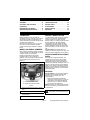
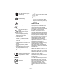
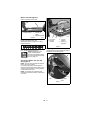
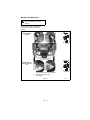
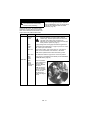
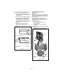
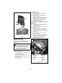
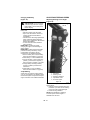
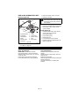
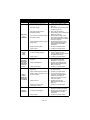
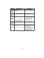
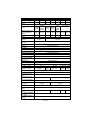
ZOOM Owner/Operator Manual Models 915055 - 1944 915057 - 2148 915059 - 2352 915065 - 1540 915067 - 1740 915501 - 1844 915502 - 1540 ENGLISH FRANÇAIS ESPAÑOL Transfer model & serial number label from product registration here. Coller l’autocollant du modèle et du numéro de série dans cet encadré. Transferir aquí la etiqueta del modelo y número de serie del registro del producto. 00367300 9/04 Printed in USA Ariens Company 655 West Ryan Street P.O. Box 157 Brillion, Wisconsin 54110-0157 USA Telephone (920) 756-2141 Facsimile (920) 756-2407 EC DECLARATION OF CONFORMITY ISSUED BY THE MANUFACTURER – DÉCLARATION DE CONFORMITÉ CE ÉMISE PAR LE FABRICANT – EU-ÜBEREINSTIMMUNGSERKLÄRUNG DES HERSTELLERS – VERKLARING VAN OVEREENSTEMMING VOOR DE EU, AFGEGEVEN DOOR DE FABRIKANT – EF OVERENSSTEMMELSESERKLÆRING UDSTEDT AF FABRIKANTEN – DICHIARAZIONE DI CONFORMITÀ CE RILASCIATA DAL PRODUTTORE – DECLARACIÓN DE CONFORMIDAD CE EMITIDA POR EL FABRICANTE – EF-SAMSVARSERKLÆRING FRA PRODUSENTEN – EG-DEKLARATIONEN OM ÖVERENSSTÄMMELSE UTFÄRDAD AV TILLVERKAREN – VALMISTAJAN ANTAMA EYVAATIMUSTENMUKAISUUSVAKUUTUS – DEKLARACJA ZGODNOŚCI Z PRZEPISAMI EC WYDANA PRZEZ PRODUCENTA – DECLARAÇÃO DE CONFORMIDADE CE EMITIDA PELO FABRICANTE We the undersigned, ARIENS COMPANY, certify that: – Nous, soussignés ARIENS COMPANY, certifions que : – Der Unterzeichnete, ARIENS COMPANY, bescheinigt, dass: – Wij, de ondergetekenden, ARIENS COMPANY, verklaren dat: – Undertegnede, ARIENS COMPANY, attesterer, at: – La sottoscritta società ARIENS COMPANY certifica che: – Nosotros, los abajo firmantes, ARIENS COMPANY, certificamos que: – Undertegnede, ARIENS COMPANY, bekrefter at: – Undertecknad, ARIENS COMPANY, intygar att: – Allekirjoittanut, ARIENS COMPANY, vakuuttaa, että: – My, niżej podpisani, ARIENS COMPANY, oświadczamy, że: – Nós, abaixo assinados, certificamos em nome da ARIENS COMPANY, que: Type: – Type : – Typ: Type: – Type: – Tipo: Tipo: – Type: – Typ: Tyyppi: – Typ: – Tipo: Riding Rotary Lawn Mower – Tondeuse à gazon autoportée rotative – AufsitzSichelmäher – Rijdende roterende grasmaaier – Havetraktor med roterende knive – Trattorino con unità di taglio rotativa – Tractor cortacésped giratorio – Plentraktor med rotorklipper – Rotoråkgräsklippare – Ajoleikkuri – Samobieżna rotacyjna kosiarka trawnikowa – Tractor Cortador de Relva – Trade Name: – Appellation commerciale : – Handelsbezeichnung: – Handelsnaam: – Firmanavn: – Nome commerciale: – Nombre comercial: – Handelsnavn: – Handelsbeteckning: – Kauppanimi: – Nazwa handlowa: – Nome da Marca: Model: – Modèle : – Modell: – Model: – Model: – Modello: – Modelo: – Modell: – Modell: – Malli: – Model: – Modelo: Cutting Width: – Largeur de coupe : – Schnittbreite: – Maaibreedte: – Klippebredde: – Larghezza di taglio: – Ancho de corte: – Klippebredde: Klippbredd: – Leikkuuleveys: – Szerokość cięcia: – Largura de corte: Ariens 915501 915502 112 102 Conforms to: – Est conforme à : – Mit den Anforderungen der folgenden Richtlinien übereinstimmt: – Voldoet aan: – Er i overensstemmelse med: – È conforme a: – Cumple con: – Er i samsvar med: – Överensstämmer med: – Täyttää seuraavat vaatimukset: – Jest zgodny z: – De acordo com: 98/37/EC, 89/336/EEC; 2000/14/EC Conformity Assessment Annex VI. – Annexe VI de l'évaluation de conformité. – Konformitätsbewertung, Anhang VI. – Bijlage VI voor beoordeling van overeenstemming. – Vurdering af overensstemmelse Anneks VI. – Annesso VI della valutazione di conformità. – Anexo VI de la evaluación de la conformidad. – Samsvarsvurdering etter vedlegg VI. – Bedömning av överensstämmelse Bilaga VI. – Vaatimustenmukaisuuden arviointi, liite VI. – Dodatek VI, Ocena zgodności. – Anexo VI da Avaliação de Conformidade. 2 Representative Measured Sound Power Level (Lwa) – Niveau de puissance acoustique représentatif mesuré (Lwa) – Repräsentativer gemessener Geräuschpegel (Lwa) – Representatief gemeten geluidsniveau (Lwa) – Repræsentativt, målt støjeffektniveau (Lwa) Livello di – potenza sonora rappresentativo rilevato (Lwa) – Nivel de potencia acústica representativo medido (Lwa) – Representativt målt lydeffektnivå (Lwa) – Representativ uppmätt ljudnivå (Lwa) – Tyypillinen mitattu äänitehotaso (Lwa) – Zmierzony reprezentatywny poziom mocy akustycznej (Lwa) – Nível de Potência de Som Medido Representativo (Lwa) Guaranteed Sound Power Level (Lwa) – Niveau de puissance acoustique garanti (Lwa) – Garantierter Geräuschpegel (Lwa) – Gegarandeerd geluidsniveau (Lwa) – Garanteret støjeffektniveau (Lwa) – Livello di potenza sonora garantito (Lwa) – Nivel de potencia acústica garantizado (Lwa) – Garantert lydeffektnivå (Lwa) – Garanterad uppmätt ljudnivå (Lwa) – Taattu äänitehotaso (Lwa) – Gwarantowany reprezentatywny poziom mocy akustycznej (Lwa) – Nível de Potência de Som Garantido (Lwa) 915501: 99 dBA 915502: 99 dBA 915501: 100 dBA 915502: 100 dBA Notified Body – Organisme notifié – Zertifizierungsstelle – Aangemelde SNCH instantie – Bemyndiget organ – Organismo notificato – Organismo 11, Route de Luxembourg notificado – Teknisk kontrollorgan – Anmält organ – Ilmoitettu laitos – L-5230 Sandweiler Organ zaświadczający – Organismo Certificador – Philip J. Smucker: Quality and Conformance Manager (Keeper of Technical File) – Responsable de la qualité et de la conformité des produits (Dépositaire de la fiche technique) – Manager Qualitätssicherung und Konformität (Archivar der technischen Akte) – Kwaliteits- en normalisatiemanager (Beheerder van technische bestand) – Chef for kvalitet og overensstemmelse (Indehaver af tekniske data) – Responsabile della qualità e della conformità del prodotto (Depositario del file tecnico) – Gerente de calidad y conformidad (Depositario del archivo técnico) – Kvalitetog samsvarsansvarlig (innehaver av teknisk fil) – Chef för kvalitet och produktöverensstämmelse (Innehavare av tekniska data) – Laadusta ja vaatimustenmukaisuudesta vastaava johtaja (Teknisen tiedoston haltija) – Kierownik do spraw jakości i zgodności (Przechowujący Dokumentację Techniczną) – Gestor de Qualidade e Conformidade (Zelador de Arquivos Técnicos) Ariens Company Brillion, WI 54110-0157 USA Signature – Signature – Unterschrift – Handtekening – Underskrift – Firma – Firma – Signatur – Namnteckning – Allekirjoitus – Podpis – Assinatura 12/10/2003 Date – Date – Datum – Datum – Dato – Data – Fecha – Dato – Datum – Päiväys – Data – Data CE Sound and Vibration – Bruits et vibrations CE – CE Geräusch- und Vibrationswerte – CE Geluid en trilling – CE støj og vibration – Livello sonoro e vibrazioni CE – Sonido y vibración CE – CE-lyd og -vibrasjon – CE ljudnivå och vibrationer – CE, melu ja tärinä – CE Dźwięku i Wibracji – Som e Vibração CE – (Ref. EN836-2001) 915502 Model: – Modèle : – Modell: – Model: – Model: – Modello: – Modelo: – Modell: – Modell: – 915501 Malli: – Model: – Modelo: Oper. Ear Sound Pressure (Lpa) in dBA – Pression acoustique aux oreilles de l’opérateur (Lpa) en dBA – Geräuschpegel am Ohr des Bedieners (Lpa) in dBA – Geluidsdruk bij het oor van de gebruiker (Lpa) in dBA – Strøjtryk ved brugerens øre (Lpa) målt i dBA – Pressione sonora all’orecchio dell’operatore (Lpa) in dBA – Presión de sonido en el oído (Lpa) in dBA – Lydtrykk ved førerens øre (Lpa) inn dBA – Ljudeffekt vid förarens öron (Lpa) i dBA – Kuljettajan korvaan kohdistuva äänenpaine (Lpa), dBA – Robocze ciśnienie akustyczne na uchu (Lpa) w decybelachA – Oper. Pressão do Som no Ouvido (Lpa) 86 87 em dBA – Vibration Measure (m/sec2) at Operator: – Mesure des vibrations (m/s2) au niveau de l’opérateur: – Vibration (m/s2) an des Bedieners: – Gemeten trilling bij (m/sec2): – Vibrationsmålinger (m/s2) ved brugerens: – Vibrazioni percepite dall’operatore (m/sec2): – Medida de vibración (m/seg2) en el operador: – Vibrasjonsmåling (m/s2) ved førerens: – Vibrationsmått (m/s2) vid förarens: – Tärinä (m/s2) kuljettajan: – Pomiar wibracji (m/sec2) u operatora: – Medida de Vibração (m/seg.2) no Operador: Hands – Mains – Hände – De handen van de gebruiker – Hænder – Mani – Manos – Hender – Händer – Käsissä – Ręce – Mãos – 2.9 X 0.76 1.4 Y 0.59 1.3 Z 1.10 Feet – Pieds – Füße – De voeten van de gebruiker – Fødder – Piedi –Pies – Føtter – Fötter – Jaloissa – Stopy – Pés – 0.28 X 0.34 0.16 Y 0.42 1.5 Z 1.19 Seat – Siège – Sitz – De bestuurdersplaats – Sæde – Sedile – Asiento – Sete – Säte – Istuimella – Siedzenie – Assento – 0.43 X 0.35 0.29 Y 0.37 0.91 Z 0.87 3 TABLE OF CONTENTS SAFETY . . . . . . . . . . . . . . . . . . . . . . . . . . 5 STORAGE . . . . . . . . . . . . . . . . . . . . . . . 25 ASSEMBLY. . . . . . . . . . . . . . . . . . . . . . . 10 TROUBLESHOOTING . . . . . . . . . . . . . . 26 CONTROLS AND FEATURES . . . . . . . . 11 SERVICE PARTS . . . . . . . . . . . . . . . . . . 28 OPERATION . . . . . . . . . . . . . . . . . . . . . . 11 ACCESSORIES . . . . . . . . . . . . . . . . . . . 28 MAINTENANCE SCHEDULE . . . . . . . . . 16 SPECIFICATIONS . . . . . . . . . . . . . . . . . 29 SERVICE AND ADJUSTMENTS . . . . . . 17 WARRANTY . . . . . . . . . . . . . . . . . . . . . . 30 INTRODUCTION THE MANUAL PRODUCT REGISTRATION Before operation of unit, carefully and completely read your manuals. The contents will provide you with an understanding of safety instructions and controls during normal operation and maintenance. All reference to left, right, front, or rear are given from operator seated in operation position and facing the direction of forward travel. The Ariens dealer must register the product at the time of purchase. Registering the product will help the company process warranty claims or contact you with the latest service information. All claims meeting requirements during the limited warranty period will be honored, whether or not the product registration card is returned. Keep a proof of purchase if you do not register your unit. Customer Note: If the dealer does not register your product, please fill out, sign, and return the product registration card to Ariens. MODEL AND SERIAL NUMBERS When ordering replacement parts or making service inquiries, know the Model and Serial numbers of your unit and engine. Numbers are located on the product registration form in the unit literature package. They are printed on a serial number label, located on the frame of your unit (figure 1). 2 1 UNAUTHORIZED REPLACEMENT PARTS Use only Ariens replacement parts. The replacement of any part on this unit with anything other than an Ariens authorized replacement part may adversely affect the performance, durability, and safety of this unit and may void the warranty. Ariens disclaims liability for any claims or damages, whether warranty, property damage, personal injury or death arising out of the use of unauthorized replacement parts. DELIVERY OE0170 1. Unit Serial Number Label 2. Engine Serial Number Label Figure 1 • Record Unit Model and Serial numbers here. Customer Note: If you have purchased this product without complete assembly and instruction by your retailer, it is your responsibility to: • Read and understand all assembly instructions in this manual. If you do not understand or have difficulty following the instructions, contact your nearest Ariens Dealer for assistance. NOTE: To locate your nearest Ariens Dealer, call 920-756-4664 or go to www.ariens.com on the internet. WARNING: Improper assembly or adjustments can cause serious injury. • Record Engine Model and Serial numbers here. GB - 4 © Copyright 2004 Ariens Company Before Attempting To Operate Your Unit: 1. Make sure all assembly has been properly completed. 2. Understand all Safety Precautions provided in the manuals. 3. Review control functions and operation of the unit. Do not operate the unit unless all controls function as described in this manual. 4. Review recommended lubrication, maintenance and adjustments. 5. Review Limited Warranty Policy. 6. Fill out a product registration card and return the card to the Ariens Company or go to www.ariens.com. DISCLAIMER Ariens reserves the right to discontinue, change, and improve its products at any time without notice or obligation to the purchaser. The descriptions and specifications contained in this manual were in effect at printing. Equipment described within this manual may be optional. Some illustrations may not be applicable to your unit. SAFETY WARNING: This cutting machine is capable of amputating hands and feet and throwing objects. Failure to observe the safety instructions in the manuals and on decals could result in serious injury or death. Slopes are a major factor related to loss-of-control and tip-over accidents. Operation on all slopes requires extra caution. Tragic accidents can occur if the operator is not alert to the presence of children. Never assume that children will remain where you last saw them. Gasoline is extremely flammable and the vapors are explosive, handle with care. Disengage attachment, stop unit and engine, remove key, engage parking brake, and allow moving parts to stop before leaving operator’s position. SAFETY ALERTS DANGER: IMMINENTLY HAZARDOUS SITUATION! If not avoided, WILL RESULT in death or serious injury. WARNING: POTENTIALLY HAZARDOUS SITUATION! If not avoided, COULD RESULT in death or serious injury. CAUTION: POTENTIALLY HAZARDOUS SITUATION! If not avoided, MAY RESULT in minor or moderate injury. It may also be used to alert against unsafe practices. NOTATIONS NOTE: General reference information for proper operation and maintenance practices. IMPORTANT: Specific procedures or information required to prevent damage to unit or attachment. SAFETY DECALS AND LOCATIONS Look for these symbols to point out important safety precautions. They mean: • Attention! • Personal Safety Is Involved! • Become Alert! • Obey The Message! ALWAYS replace missing or damaged Safety Decals. Refer to figure 2 for Safety Decal locations. 1. Caution! The safety alert symbol is used in decals and with this manual. Understand the safety message. It contains important information about personal safety. GB - 5 • • • • • Maximum Tongue weight: 30 lbs. Maximum Trailer weight: 300 lbs. Do not use hitch with bagger attached. Do not use on steep hills or slopes. Do not park on hills when trailer is attached. • Do not use with any ground engaging equipment. 1 7 2 3 5 6 077541 4 OE0050 Figure 2 2. Danger! NO STEP! Always keep feet away from rotating parts. Avoid injury - Stay clear of rotating parts. OL1813 OL1816 4. Warning! 3. Danger! Always stand clear of discharge area. Always keep feet and hands away from rotating parts. OL1814 OL1809 Do not operate mower unless bagger is attached or guards are in operating position. Always stand clear of discharge area. Do not direct discharge toward other people. OL1810 OL1815 5. Danger! To Avoid Serious Injury or Death Keep people away from unit while operating. Read the operator’s manual. OL18111 OL1801 Shut off engine, remove key, and read manual before you adjust or repair unit. Keep children and others away from unit while operating. OL1812 OL1802 GB - 6 OL1803 Never direct discharge toward other people. Thrown objects can cause injury. Fill fuel tanks to 2-1/2 in. (6.35 cm) below bottom of filler neck. Look down and behind before and while backing. • Never fill fuel tank when engine is running, hot or unit is indoors. Never overfill fuel tank. • Replace fuel cap securely and clean up spilled fuel. OL1804 OL1805 SAFETY RULES Never carry children. OL1806 10 MAX OL1807 Go up and down slopes, not across. DO NOT operate on slopes over 10°. • If machine stops going uphill, stop blade and back down slowly. • Avoid sudden turns. • Keep safety devices (guards, shields, switches, etc.) in place and working. • Check interlock system per manual before use. • Understand location and function of all controls. • Never allow operation by untrained persons. • Disengage PTO, stop unit and engine, set parking brake and remove key before making any inspections, repairs, etc. 6. Hot Surfaces! DO NOT touch parts which are hot from operation. ALWAYS allow parts to cool. OL1801 7. Caution No smoking. If unit is to be used by someone other than original purchaser; loaned, rented or sold, ALWAYS provide this manual and any needed safety training before operation. Only the user can prevent and is responsible for accidents or injuries occurring to themselves, other people or property. Read, understand, and follow all safety practices in Owner/Operator Manual before assembling, using or working on this mower. ALWAYS remove key from ignition and wire from spark plug before assembly, or working on this unit. Inspect unit before each use for: missing or damaged decals and shields, correctly operating safety interlock system, and deterioration of grass catchers. Replace or repair as needed. ALWAYS check overhead and side clearances carefully before operation. ALWAYS be aware of traffic when crossing or operating along streets or curbs. Keep children, people, and pets away. Be alert and shut off unit if anyone enters work area. Keep children under watchful care of a responsible adult. NEVER allow children to operate or play on or near unit. Keep area of operation clear of all toys, and debris. Thrown objects can cause injury. Stay alert for hidden hazards, holes, and ruts. Avoid uneven or rough terrain. DO NOT operate near drop-offs, ditches, or embankments. Unit can suddenly turn over if a wheel is over the edge of a cliff or ditch, or if an edge caves in. Dust, fog, etc. can reduce vision and cause an accident. Operate unit only when there is good visibility and light. Data indicates that operators, age 60 and above, are involved in a larger percentage of riding mower related injuries. These operators should evaluate their ability to operate the riding mower safely enough to protect themselves and others from serious injury. GB - 7 Only trained adults may operate unit. Training includes being familiar with controls and actual operation. NEVER operate unit after or during the use of medication, drugs or alcohol. NEVER allow anyone to operate this unit when their alertness or coordination is impaired. Wear adequate safety gear, sturdy shoes, and protective gloves. DO NOT wear loose clothing or jewelry and tie back hair that may get caught in rotating parts. Protect eyes, face and head from objects that may be thrown from unit. Wear appropriate hearing protection. Always wear safety goggles or safety glasses with side shields when operating mower. Avoid sharp edges. Sharp edges can cut. Moving parts can cut off fingers or a hand. ALWAYS keep hands and feet away from all rotating parts during operation. Rotating parts can cut off body parts. ALWAYS keep hands away from all pinch points. Start and operate unit only when seated in operator’s position. Steering control levers must be in neutral, PTO disengaged and parking brake set when starting engine. ALWAYS keep body and hands away from pin holes or nozzles which eject hydraulic fluid under pressure. DO NOT touch unit parts which might be hot from operation. Allow parts to cool before attempting to maintain, adjust or service. NEVER place your hands or any part of your body or clothing inside or near any moving part while unit is running. NEVER direct discharge towards persons or property. Thrown objects may ricochet back towards operator. ALWAYS stand clear of the discharge area. ALWAYS disengage attachment, stop unit and engine, remove key, engage parking brake, and allow moving parts to stop before leaving operator’s position. Use extreme caution on gravel surfaces. Disengage PTO when attachment is not in use and when crossing gravel surfaces. DO NOT operate unit if safety interlock system is damaged or disabled. Check safety interlock before each use. ALWAYS remove key to prevent unauthorized use. DO NOT operate at too fast a rate. Slow down before turning. Stop engine before removing grass catcher or unclogging chute. DO NOT mow on wet grass. Reduced traction could cause sliding. DO NOT try to stabilize the machine by putting your foot on the ground. Know the weight of loads. Limit loads to those you can safely control and the unit can safely handle. ALWAYS keep protective structures, guards and panels in good repair, in place and securely fastened. Do not operate without either entire grass catcher or the discharge guard in place. DO NOT operate in reverse unless absolutely necessary. ALWAYS look down and behind before and while backing; especially for children. Follow the manufacturer’s recommendations for wheel weights or counterweights to improve stability when using attachments. NEVER carry passengers–especially children–even with blades off. Use extra care when approaching blind corners or objects that may obscure vision of hidden obstacles and children. If you cannot back up a slope or you feel uneasy on it, do not mow it. Mow up and down slopes, not across them. Use slow speed on any slope. Tires may lose traction on slopes even though the brakes are functioning properly. Keep all movements on the slope slow and gradual. DO NOT make sudden changes in speed or direction. Use extra care while operating machines with grass catcher or other attachments. They can affect stability of the machine. Avoid starting, stopping, or turning on a slope. If tires lose traction, disengage the blades and proceed slowly straight down the slope. DO NOT operate on slopes over 10°. DO NOT park on slopes unless necessary. If unit is parked on a slope, ALWAYS chock or block wheels and set parking brake. DO NOT disengage or bypass transmission and coast downhill. Tow only with a machine that has a hitch designed for towing. Do not attach towed equipment except at the hitch point. Follow the manufacturer’s recommendations for weight limits for towed equipment and towing on slopes. NEVER allow children or others in or on towed equipment. On slopes, the weight of the towed equipment may cause loss of traction and loss of control. Travel slowly and allow extra distance to stop. Use extra care when loading or unloading unit onto trailer or truck. Secure unit chassis to transport vehicle. NEVER secure from rods or linkages that could be damaged. DO NOT transport machine while engine is running. GB - 8 ALWAYS turn off power to attachment and shut off fuel when transporting unit. Keep unit free of grass clippings, leaves, and other debris. Clean up oil or fuel spills. This product is equipped with an internal combustion type engine. DO NOT use unit on or near any unimproved, forest-covered or brush covered land unless exhaust system is equipped with a spark arrester meeting applicable local, state or federal laws. A spark arrester, if it is used, must be maintained in effective working order by operator. Fuel is highly flammable and its vapors are explosive. Handle with care. Use an approved fuel container. NO smoking, NO sparks, NO flames. ALWAYS allow engine to cool before servicing. NEVER fill fuel tank when engine is running or hot from operation. NEVER fill or drain fuel tank indoors. NEVER overfill fuel tank. Replace fuel cap securely and clean up spilled fuel. NEVER fill containers inside a vehicle or on a truck or trailer bed with a plastic liner. Always place containers on the ground away from your vehicle before filling. When practical, remove gas-powered equipment from the truck or trailer and refuel it on the ground. If this is not possible, then refuel such equipment on a trailer with a portable container, rather than from a gasoline dispenser nozzle. Keep the nozzle in contact with the rim of the fuel tank or container opening at all times until fueling is complete. Do not use a nozzle lock-open device. If fuel is spilled on clothing, change clothing immediately. Avoid Electric Shock. Objects contacting both battery terminals at the same time may result in injury and unit damage. DO NOT reverse battery connections. Explosive Gases from battery can cause death or serious injury. Poisonous battery fluid contains sulfuric acid and its contact with skin, eyes or clothing can cause severe chemical burns. NO flames, NO sparks, NO smoking near battery. ALWAYS wear safety glasses and protective gear near battery. Use insulated tools. DO NOT TIP battery beyond a 45° angle in any direction. ALWAYS keep batteries out of reach of children. Battery posts, terminals and related accessories contain lead and lead compounds, chemicals known to the State of California to cause cancer and reproductive harm. Wash hands after handling. Reverse connections may result in sparks which can cause serious injury. Always connect positive (+) lead of charger to positive (+) terminal, and negative (-) lead to negative (-) terminal. ALWAYS disconnect negative (-) cable FIRST and positive (+) cable SECOND. ALWAYS connect positive (+) cable FIRST, and negative (-) cable SECOND. A frozen battery can explode and result in death or serious injury. DO NOT charge or jump start a battery containing frozen fluid. Thaw the battery before putting on a charger or jump starting. ALWAYS keep protective structures, guards, and panels in good repair, in place and securely fastened. NEVER modify or remove safety devices. DO NOT change engine governor settings or over-speed engine. Fumes from engine exhaust can cause injury or death. DO NOT run engine in an enclosed area. Always provide good ventilation. ALWAYS maintain unit in safe operating condition. Damaged or worn out muffler can cause fire or explosion. Stop and inspect equipment if you strike an object or if there is an unusual vibration. Repair, if necessary, before restarting. Never make adjustments or repairs with the engine running. Mower blades are sharp and can cut you. Wrap the blade(s) or wear gloves, and use extra caution when servicing them. NEVER weld or straighten mower blades. Rotation of one blade may cause rotation of the other blades. Check brake operation frequently. Adjust and service as required. Keep all hardware properly tightened. Stored energy in springs can cause injury. Maintain or replace safety and instruction labels, as necessary. Never store the machine or fuel container inside a building where there is an open flame, such as a water heater. Shut off fuel (if provided) and allow engine to cool completely before storing in closed area or covering unit. Clean grass and debris from unit, especially from around muffler and engine, to help prevent fires. For extended storage, clean unit thoroughly. See Engine Manual for proper storage. Use only attachments or accessories designed for your unit. Check attachment components frequently. If worn or damaged, replace with manufacturer’s recommended parts. GB - 9 ASSEMBLY Check Safety Interlock System WARNING: AVOID INJURY. Read and understand the entire Safety section before proceeding. WARNING: Safety interlock failure and improper operation of unit can result in death or serious injury. Check system before each use to make sure it is functioning properly. Tools Required • Adjustable wrench • Petroleum jelly or dielectric grease. Unpack Unit See Safety Interlock System on page 11. Remove unit and all other components from the shipping container. Engage transmission bypass lever (see MOVING UNIT MANUALLY on page 15). Push unit from container onto a level surface. Disengage transmission bypass lever. Check function of all controls See OPERATION on page 11. 1 Connect Battery 2 3 See Battery Removal and Installation on page 22 and perform steps 2 and 3 in the installation section. Place Unit in Operating Position (figure 3): 1. Tip seat back. NOTE: Models 915501 and 502 must use the flat washer and nut to secure the seat to the unit. 2. Secure seat to unit with clamping knob (915065, 067, 055, 057, 059) or flat washer and nut (915501, 502) (located in literature pack). 3. Install steering levers on the handlebar brackets with mounting hardware. 4. Adjust steering levers (see ADJUSTING STEERING LEVERS on page 23). 4 Check Engine Oil Level Refer to Engine Manual. Check Tire Pressure See SPECIFICATIONS on page 29. Level Mower Deck See LEVELLING AND ADJUSTING PITCH OF MOWER DECK on page 19. Fill Fuel Tanks See FILLING FUEL TANKS on page 14. Adjust Seat See Adjusting Seat on page 13. 5 OE0190 1. Clamping Knob (915065, 067, 055, 057, 059) or flat washer and nut (915501, 502) 2. Seat 3. Steering Lever 4. Mounting Hardware 5. Handlebar Brackets Figure 3 GB - 10 CONTROLS AND FEATURES 2 1 4 3 5 6 7 15 14 7 13 12 11 10 OE0220 Figure 4 1. 2. 3. 4. 5. 6. 7. 8. Ignition Switch PTO Switch Throttle Lever Seat Steering Levers Parking Brake Fuel Tanks Headlights (915067, 055, 057, 059, 501) 9. 10. 11. 12. 13. 14. 15. 8 9 Axle Lock (915067, 055, 057, 059, 501) Mower Lift Pedal Mower Deck Discharge Chute Fuel Shut-Off Valve Choke Control (915055, 057, 059, 501) Hour meter (915067, 055, 057, 059, 501, and optional on 915065, 502) OPERATION WARNING: AVOID INJURY. Read and understand the entire Safety section before proceeding. Safety Interlock System WARNING: Safety interlock failure and improper operation of unit can result in death or serious injury. Check system before each use to make sure it is functioning properly. CONTROLS AND FEATURES See figure 4 for all controls and features locations. Perform the following tests to ensure the safety interlock system is working properly. If the unit does not perform as stated contact your Ariens dealer for repairs. Test Steering Lever PTO Parking Brake 1 Neutral Position Off Engaged Engine Starts 2 Neutral Position On Engaged Doesn’t Start Doesn’t Start 3 Neutral Position Off Disengaged 4*+ Out of Neutral Position Off Disengaged Shuts Off 5*+ Neutral Position On Engaged Shuts Off * Test with engine running. + Operator lifts off seat. GB - 11 Ignition Switch 1 2 3 4 OE0004 Power Take-Off (PTO) Switch Operate ignition switch with a removable key. Ignition switch has four positions: Stop (1), Headlight (2), Run (3), Start (4). See STARTING AND SHUTTING OFF ENGINE on page 14 for detailed instructions on how to start engine. 1 2 OE005 Fuel Shut-Off Valve Throttle Lever (915065, 067, 502) 1 Choke (1) – Use to start a cold engine. 3 1 OFF LEFT TANK RIGHT TANK 2 2 Engages (2) and disengages (1) mower blades. Fast (2) – Increases engine speed. Controls fuel flow from left fuel tank (1) or right fuel tank (2). Open the valve to operate the engine. Turn the valve to off (3) when storing or transporting the unit. OF1881 Hour Meter (915067, 055, 057, 059, 501, and Optional on 915065, 502) 3 OE0002 Records total number of hours engine has been run. NOTE: Hour meter will continue to run if ignition key is left in the run position with the engine turned off. Slow (3) – Decreases engine speed. Throttle Lever (915055, 057, 059, 501) 1 2 OE0043 Fast (1) – Increases engine speed. OF1881 Steering Levers • Reverse (1) – Pull both steering levers backward. • Forward (2) – Push both steering levers forward. • Left (3) – Pull left steering lever back or push right steering lever forward or a combination of both. • Right (4) – Pull right steering lever back or push left steering lever forward or a combination of both. Slow (2) – Decreases engine speed. Choke Control (915055, 057, 059, 501) Use to start a cold engine. Pull choke control out to choke engine. Push choke control in when engine is warm. 1 2 3 4 OE0058 1 Engages (2) and disengages (1) parking brake. 07757600B Parking Brake 0E0030 2 OE0049 NOTE: To stop, return both steering levers to neutral. NOTE: The steering levers must be in the neutral position to start the engine. NOTE: The parking brake must be disengaged prior to moving the steering levers from the neutral position. GB - 12 Mower Lift Pedal (Figure 5) Raises and lowers mower deck. 2 1 3 2. Mower Lift Pedal 3. Adjustment Hole Figure 5 OE0060 1. Adjustment Pin 1 1 05304900 OE0090 2 3 1. Front Axle 2. Pivoting Position NOTE: The adjustment pin is used to set the height of the mower deck. See SPECIFICATIONS on page 29 for cutting height dimensions. 765 4 3 2 4 OE0240 3. Lockout Position 4. Axle Lock Hardware Figure 6 Adjusting Seat Lift adjustment lever and slide seat forward or backward to the desired position. 1 08088400A Press mower lift pedal and install adjustment pin in the desired adjustment hole. NOTE: Adjusting the seat further forward will help increase the leverage in lifting the mower deck (see Adjusting Seat on page 13). Axle Locks (915067, 055, 057, 059, 501) (Figure 6) NOTE: The unit comes shipped with the front axle in the lockout position. If a pivoting front axle is needed: Remove axle lock hardware from lockout position and install axle lock hardware in pivoting position on both sides of front axle. NOTE: To lock front axle, install axle lock hardware in the lockout position on both sides of the axle. 2 1. Seat GB - 13 OE0150 2. Adjustment Lever Figure 7 FILLING FUEL TANKS Stopping the Engine 1. Clean fuel caps and surrounding area to prevent dust, dirt, and debris from entering fuel tanks. 2. Remove fuel caps. IMPORTANT: See Engine Manual for correct type and grade of fuel. 3. Fill fuel tanks to 2-1/2 in. (6.35 cm) below bottom of filler neck. See SPECIFICATIONS on page 29 for capacity of fuel tanks. 4. Replace fuel caps. STOPPING IN AN EMERGENCY Bring steering levers back to neutral, set parking brake, and turn off engine. STARTING AND SHUTTING OFF ENGINE Starting the Engine NOTE: Disengage the PTO, engage the parking brake, and place the steering levers in neutral prior to starting the engine. 1. Set throttle lever to choke (915065, 067, 502) or engage choke control (915055, 057, 059, 501) for a cold engine. Set throttle lever at 1/3 throttle for a warm engine. IMPORTANT: DO NOT operate starter for more than 15 seconds per minute as damage can occur. 2. Turn ignition key to start position and release once the engine has started. 3. After engine starts, set throttle lever to fast. Disengage choke control (915055, 057, 059, 501). IMPORTANT: Let the engine warm up several seconds to several minutes depending on outside temperature. 1. 2. 3. 4. Stop unit. Disengage PTO. Set throttle lever to slow. Turn ignition switch to off position and remove key. 5. Set parking brake. OPERATING MOWER 1. Start engine. 2. Set throttle lever to fast. IMPORTANT: Never engage PTO if mower is plugged with grass or other material. 3. Engage PTO to start mower blades. NOTE: The parking brake must be disengaged prior to moving the steering levers from the neutral lockout position. 4. Release parking brake. 5. Use steering levers to move the unit. 6. Disengage PTO to stop mower blades. TRANSPORTING UNIT ALWAYS shut off engine, set parking brake, remove key, and close fuel shut-off valve or drain fuel when transporting unit on a truck or trailer. Tie unit down securely. Do not tie down by linkages, guards, cables or other parts that may be damaged. FOR BEST PERFORMANCE Cut grass when it is dry. Keep mower blades sharp. Keep mower deck properly leveled. Adjust anti-scalp rollers to prevent scalping. Do not set height of cut too low. For very tall grass, mow twice. Do not travel too fast. Mow with the engine set at full throttle. When mulching, only remove 1/3 of grass length per cutting. Discharge clippings into areas already cut. Vary cutting pattern with each mowing. Do not allow grass or debris to collect inside of mower deck. Clean after each use. GB - 14 MOVING UNIT MANUALLY WARNING: DO NOT disengage or bypass transmission and coast downhill. Disengage (2) transmission bypass levers to drive unit and engage (1) transmission bypass levers to push unit manually (figure 8). 1 Models 915065 and 502 2 1 2 05305600 1 Models 915055, 057, 059, 067, and 501 2 05305200 2 1 1. Transmission Bypass Lever Engaged 2. Transmission Bypass Lever Disengaged Figure 8 GB - 15 OE0260 MAINTENANCE SCHEDULE WARNING: AVOID INJURY. Read and understand the entire Safety section before proceeding. IMPORTANT: Proper maintenance can prolong the life of unit. The following chart shows the recommended service schedule. Refer to the maintenance instructions in the Engine Manual for additional information. Interval Task Check Safety Interlock System Each Use NOTE: To have full access to the engine, the seat must be tipped forward (see TIPPING SEAT FORWARD on page 17) and the hood opened (see OPENING AND CLOSING HOOD on page 18). Action WARNING: Safety interlock system failure and improper operation of unit can result in death or serious injury. Test this system each time the unit is operated. If this system does not function as described, do not operate until repairs are made (see Safety Interlock System on page 11). Check Parking Brake Engage parking brake and engage transmission bypass lever (see MOVING UNIT MANUALLY on page 15). Push unit. If unit rolls, contact your Ariens Dealer. Clean Unit Clean engine, battery, seat, mower deck, etc. of all dirt and debris. Do not use solvents, hard cleaners, or abrasives. NOTE: Protect painted surfaces with automotive type wax. Check Tires See SPECIFICATIONS on page 29 for correct tire pressure. Check Mower Blades Check for worn or damaged mower blades (see SHARPENING MOWER BLADE on page 20). Follow Engine Manual Maintenance Schedule Perform scheduled engine maintenance. Refer to Engine Manual for detailed instructions. NOTE: To drain the oil, use the oil drain petcock (1) supplied with unit, not the drain plug that is shown in the Engine Manual. GB - 16 1 Interval Task Action Check Battery Keep battery and battery terminals clean (see Cleaning Battery and Battery Cables on page 22). Lubricate Unit Apply grease to zerk (1) on each front wheel 25 Hours or Every Season 1 50 Hours or Every Season 100 Hours or Every Season Check Fasteners Check mower blade mounting hardware and all other fasteners. Replace fasteners that are missing or damaged. Tighten all nuts and bolts to the correct torque value. Check All Belts Replace worn or deteriorated belts. • Check hydrostatic belt (see REPLACING HYDROSTATIC BELT on page 25 for hydrostatic belt location). • Check PTO belt (see REPLACING PTO BELT on page 24 for PTO belt location). SERVICE AND ADJUSTMENTS WARNING: AVOID INJURY. Read and understand the entire Safety section before proceeding. 1 2 TIPPING SEAT FORWARD Remove clamping knob (915065, 067, 055, 057, 059) or flat washer and nut (915501, 502) and tip seat forward to access the battery and engine. NOTE: Models 915501 and 502 must use the flat washer and nut to secure the seat to the unit. Tip seat back and secure to unit with clamping knob (915065, 067, 055, 057, 059) or flat washer and nut (915501, 502) (figure 9). 1. Clamping Knob (915065, 067, 055, 057, 059) or flat washer and nut (915501, 502) 2. Seat Tipped Forward OE0300 Figure 9 GB - 17 OPENING AND CLOSING HOOD REMOVING MOWER DECK To open, pull up on the front of the hood to open and push down on top of hood to close until hood snaps into hood clips (figure 10). Remove (Figure 11) 2 1 1. Remove PTO belt from electric clutch (see REPLACING PTO BELT on page 24). NOTE: Perform step 2 and 3 for the right and left side of unit. 2. Remove guide arm from front mount bracket. 3. Remove rear lift link, rear trunnion, front lift link, and front trunnion from mower deck and mower lift. 4. Slide mower deck out from under unit. Install (Figure 11) 1. Slide mower deck under unit. NOTE: Perform step 2 and 3 for the right and left side of unit. 2. Install rear lift link, rear trunnion, front lift link, and front trunnion on mower deck and mower lift. 3. Install guide arm on front mount bracket. 4. Install PTO belt on electric clutch (see REPLACING PTO BELT on page 24). 1. Hood Clip 2. Hood Tipped Open Figure 10 OE0140 GB - 18 7 8 5 6 5 4 9 3 2 1. 2. 3. 4. 5. Mower Deck Front Trunnion Front Lift Link Front Mount Bracket Mower Lift 6. 7. 8. 9. Guide Arm PTO Belt Rear Trunnion Rear Lift Link 1 Figure 11 LEVELLING AND ADJUSTING PITCH OF MOWER DECK OE0230 IMPORTANT: The distance from rear edge of mower blades to the ground MUST NOT exceed 3 in. (7.6 cm) (figure 13). Mower Deck Shown 1 2 From The Side 3 Adjust on a level surface, with the tires inflated to the correct air pressure (see SPECIFICATIONS on page 29). Level Mower Deck 1. Install adjustment pin in the fourth adjustment hole (figure 12). 2 6 1 1. Mower Deck 2. Mower Blade 3. Front of Mower Deck 1. Adjustment Pin 2. Mower Lift Pedal OE0060 Figure 12 2. Rotate the right and left mower blades until the ends of both mower blades are facing rearward (figure 13). NOTE: The rear blade cutting height should be 2-7/8 to 3 in. (7.3 to 7.6 cm) from rear edge of mower blades to the ground on both blades (figure 13). 3. 4. 5. 6. GB - 19 5 4 4. Front Blade Cutting Height 5. Ground 6. Rear Blade Cutting Height Figure 13 OE0010 Measure from rear edge of mower blades to the ground (figure 13). Perform steps 5 through 7 if the measurement is too high or too low on either side of mower deck. Remove rear lift link and rear trunnion from mower deck and mower lift (figure 11). • TO RAISE the mower deck, turn rear trunnion clockwise several turns. • TO LOWER the mower deck, turn rear trunnion counterclockwise several turns. Install rear trunnion and rear lift link on mower deck and mower lift (figure 11). 7. Check that the mower deck is level: a.Rotate right and left mower blades to face side-to-side. b.Measure outer edge of mower blades to ground. Measurement must be within 1/4 inch (6.35 mm). • If mower deck is not level, repeat steps 5 and 6. • If mower deck is level, record the distance from rear edge of mower blades to the ground and then adjust pitch of mower deck. Adjust Pitch of Mower Deck IMPORTANT: The mower blade end used to level the mower deck must be used to adjust the pitch of the mower deck. 1. Rotate the right and left mower blades 180 degrees until the end of the mower blade that was used to level the mower deck is facing forward (figure 13). NOTE: The front blade cutting height should be 1/16 - 1/4 in. (1.59 - 6.35 mm) lower than the rear blade cutting height (figure 13). 2. Measure from front edge of right and left mower blades to the ground. 3. Subtract front blade cutting height measurement from rear blade cutting height measurement (figure 13). 4. Perform steps 5 through 7 if the front blade cutting height is too high or too low on either side on either side of mower deck. 5. Remove front lift link and front trunnion from mower deck and mower lift (figure 11). • TO RAISE the mower deck, turn front trunnion clockwise several turns. • TO LOWER the mower deck, turn front trunnion counterclockwise several turns. 6. Install front trunnion and front lift link on mower deck and mower lift (figure 11). 7. Check mower deck pitch. • If mower deck pitch is not correct, repeat steps 2 through 6. • If mower deck pitch is correct, the adjustment is complete. REPLACING MOWER BLADE Remove (Figure 14) CAUTION: Mower blades are sharp and can cut you. Wrap the blades or wear gloves, and use extra caution when servicing them. 1. Block mower blades to prevent rotation. 2. Remove mounting hardware and mower blades from mower deck. Install (Figure 14) 1. Install mower blades on mower deck with mounting hardware. 2. Torque 5/8-inch hex bolt to 80 to 120 lbf-ft (108 to 163 N•m). 1 2 4 3 1. Flat Washer 2. Bevel Washer 3. 5/8-inch Hex Bolt 4. Mower Blade Figure 14 OE0039 SHARPENING MOWER BLADE CAUTION: DO NOT sharpen mower blade while on unit. An unbalanced mower blade will cause excessive vibration and eventual damage to unit. Check mower blade balance prior to reinstalling mower blades. NEVER weld or straighten mower blades. 1. Remove mower blade from unit (see REPLACING MOWER BLADE on page 20). Ariens recommends having mower blades sharpened by a professional. Contact your Ariens dealer. Discard mower blade if (figure 15): • more than 1/2 in. (1.27 cm) of metal is removed. • the air lift erosion area is eroded. • the mower blade is bent or broken. GB - 20 Do not change angle of cutting edge or round the corner at the end of mower blade. 2. Sharpen mower blade by removing an equal amount of material from each end of mower blade. 3. Check mower blade balance by sliding mower blade on an unthreaded bolt. If blade is balanced, it should remain in a horizontal position. If either end of mower blade moves downward, sharpen the heavy end until mower blade is balanced. 4. Install mower blade on unit (see REPLACING MOWER BLADE on page 20). DO NOT Sharpen to this Pattern ADJUSTING ANTI-SCALP ROLLER NOTE: The anti-scalp rollers are intended to prevent lawn scalping, not to control cutting height. All anti-scalp rollers should be set at the same height. See figure 16 for anti-scalp locations on models 915067, 055, 057, 059, 501. See figure 17 for anti-scalp locations on models 915065 and 502. There are two positions: • Highest Position: Use to disable anti-scalp feature. • Lowest Position: Use for all cutting positions. In the lowest position the anti-scalp rollers will touch the ground. Models 915067, 055, 057, 059, 501 1 Sharpen to this Pattern 3 2 DISCARD if more than 1/2 in. (1.27 cm) 2 1 1. Air Lift Erosion Area 2. Cutting Edge Figure 15 OE0052 3 1 2 1. Anti-scalp Roller GB - 21 2. Lowest Position 3. Highest Position Figure 16 OE0038 Install (Figure 18) Models 915065 and 502 1. Install battery on the unit with battery hold-down bracket. 2. Connect positive (+) cable first, then negative (–) cable. 3. Apply petroleum jelly or dielectric grease to battery cable ends and terminals. 4. Tip seat back (see TIPPING SEAT FORWARD on page 17). 1 3 Cleaning Battery and Battery Cables (Figure 18) 2 1. Anti-scalp Roller 2. Lowest Position 3. Highest Position Figure 17 OE0310 1. Tip seat forward (see TIPPING SEAT FORWARD on page 17). 2. Disconnect negative (–) cable first, then positive (+) cable. 3. Clean battery cable ends, negative (–) terminal, and positive (+) terminal with a wire brush and rinse with a weak baking soda solution. 4. Connect positive (+) cable first, then negative (–) cable. 5. Apply petroleum jelly or dielectric grease to battery cable ends and terminals. 6. Tip seat back (see TIPPING SEAT FORWARD on page 17). SERVING BATTERY 1 NOTE: Unit comes equipped with a maintenance-free battery that requires no regular maintenance except cleaning the terminals. 6 WARNING: Battery posts, terminals and related accessories contain lead and lead compounds, chemicals known to the State of California to cause cancer and reproductive harm. Wash hands after handling. 2 5 Battery Removal and Installation 4 Remove (Figure 18) 1. Tip seat forward (see TIPPING SEAT FORWARD on page 17). 2. Disconnect negative (–) cable first, then positive (+) cable. 3. Remove battery hold-down bracket and battery from unit. 1. Battery Hold-Down Bracket 2. Negative (–) Cable GB - 22 3 3. Negative (–) Terminal 4. Battery 5. Positive (+) Terminal 6. Positive (+) cable OE0120 Figure 18 Charging the Battery ADJUSTING STEERING LEVERS (Figure 18) Adjusting Steering Lever Height (Figure 19) WARNING: FROZEN BATTERIES CAN EXPLODE and result in death or serious injury. DO NOT charge a frozen battery. Let the battery thaw before charging. 1 Follow First Aid directions for contact with battery fluid. • External Contact: Flush with water. • Eyes: Flush with water for at least 15 minutes and get medical attention immediately! • Internal Contact: Drink large quantities of water. Follow with Milk of Magnesia, beaten egg or vegetable oil. Get medical attention immediately! • In case of internal contact, DO NOT induce vomiting! IMPORTANT: DO NOT fast charge. Charging at a higher rate will damage or destroy battery. IMPORTANT: ALWAYS follow information provided on battery and battery charger. Contact battery and battery charger manufacturers’ for detailed instructions. 1. Remove battery from unit (see Battery Removal and Installation on page 22). 2. Place battery in a well-ventilated area. 3. Connect positive (+) lead of charger to positive (+) terminal, and negative (–) lead of charger to negative (–) terminal. 4. Charge battery according to battery charger and battery manufacturers’ instructions. 5. Install battery on unit (see Battery Removal and Installation on page 22). 5 2 3 4 Jump-Starting 1. 2. 3. 4. 5. Ariens does not recommend jump-starting your unit. Jump-starting can damage engine and electrical system components. See your engine manual for more detailed information. Handlebar Steering Lever Mounting Hardware Adjustment Holes Eccentric Spacer Figure 19 OE0046 NOTE: Perform steps 1 and 2 for both steering levers. 1. Remove mounting hardware and move handlebar up or down until the steering levers are at the appropriate height. 2. Install mounting hardware. NOTE: Align handlebars by adjusting eccentric spacer until the height of handlebars are the same. GB - 23 REPLACING PTO BELT Forward and Reverse Speed Adjustment Remove (Figure 21) (Figure 20) 1. Lower mower deck to the ground. IMPORTANT: The unit should track within 2 feet (0.61 m) of a straight line for 30 feet (9.14 m). The travel of the steering levers may need adjustment if: • The unit turns to the right or left when both steering levers are pushed as far forward as possible. • The unit turns to the right or left when both steering levers are pulled back as far rearward as possible. NOTE: The side the unit turns toward indicates that the wheel on that side is turning slower than the other wheel. Either the wheel that is turning faster needs to slow down or the wheel that is turning slower needs to be sped up to allow the unit to travel in a straight line. 1. Determine which way the unit turns. 2. Tip seat forward (see TIPPING SEAT FORWARD on page 17). NOTE: The forward travel adjustment bolt adjusts the forward travel of the steering lever. The rear travel adjustment bolt adjusts the rearward travel of the steering lever. 3. Adjust speed by: • Turning adjustment bolt clockwise to decrease steering lever travel. • Turning adjustment bolt counter clockwise to increase steering lever travel. 2 1 2. Remove belt covers from mower deck. CAUTION: Use care when releasing idler spring tension. Keep body parts well away from idler when performing this operation. 3. Hook a puller into idler hole and pull idler arm towards outside of unit until tension is removed from PTO belt. 3 2 4 5 6 1 7 1. 2. 3. 4. Idler Spring Electric Clutch PTO Belt Idler Hole 5. Idler Pulley 6. Idler Arm 7. Belt Cover Figure 21 OE0080 4. Remove PTO belt from left mower deck pulley. 5. Slowly release idler arm until tension is removed from idler spring. 6. Remove PTO belt from mower deck and electric clutch. Install (Figure 21) 3 1. Forward Travel Adjustment Bolt 2. Rear Travel Adjustment Bolt 3. Steering Lever NOTE: Do not install PTO belt on left mower deck pulley in step 1. 1. Install PTO belt on electric clutch and mower deck. 2. Hook a puller into idler hole and pull idler arm towards outside of unit until PTO belt can be routed around left mower deck pulley. 3. Slowly release idler arm until idler pulley rests firmly against PTO belt. 4. Install belt covers on mower deck. OE0330 Figure 20 GB - 24 REPLACING HYDROSTATIC BELT Remove (Figure 22) 2. Disconnect electric clutch connector. 3. Remove clutch stop. CAUTION: Use care when releasing idler spring tension. Keep body parts well away from idler when performing this operation. 2 1 3 4 2 4. Disconnect idler spring. 5. Remove hydrostatic belt from hydrostatic transmission pulleys, pulley, electric clutch, and idler. 8 Install (Figure 22) 7 6 1. Hydrostatic Belt 2. Hydrostatic Transmission Pulley 3. Electric Clutch Connector 1. Install hydrostatic belt on idler, electric clutch, pulley, and hydrostatic transmission pulleys. 2. Connect idler spring. 3. Install clutch stop. 4. Connect electric clutch connector. 5. Install PTO belt (see REPLACING PTO BELT on page 24). 5 4. 5. 6. 7. 8. Figure 22 Pulley Clutch Stop Electric Clutch Idler Idler Spring OE0051 1. Remove PTO belt (see REPLACING PTO BELT on page 24). STORAGE Short Term Storage Long Term Storage IMPORTANT: NEVER clean unit with high-pressure water or store unit outdoors. Remove all dirt, grease, leaves, etc. Store in a clean dry area. Inspect unit for signs of wear or damage. Ensure all fasteners are properly tightened. Follow all instructions under Short Term Storage. Remove and fully charge battery. Store in a clean dry area. Drain fuel from fuel tank. Refer to Engine Manual for the proper engine storage procedures. Touch up all scratched or chipped paint surfaces. GB - 25 TROUBLESHOOTING PROBLEM Engine will not crank/start. Engine runs rough. PROBABLE CAUSE 1. Check safety interlock system (see Safety Interlock System on page 11). 2. Fuel tanks empty. 2. Fill fuel tanks (see FILLING FUEL TANKS on page 14). 3. Fuel shut-off valve closed. 3. Open fuel shut-off valve. 4. Discharged battery. 4. Charge battery (see Charging the Battery on page 23). 5. Poor connection between battery and battery cables. 5. Tighten battery cables and/or clean battery and battery cables (see Cleaning Battery and Battery Cables on page 22). 6. Spark plug wire(s) loose or spark plug(s) faulty. 6. Connect spark plug wire(s) or replace spark plug(s). Refer to Engine Manual for detailed instructions. 7. Faulty electrical system. 7. Contact your Ariens Dealer. 8. Faulty engine. 8. Contact your Ariens Dealer. 1. Choke engaged. 1. Disengage choke. 2. Air filter cartridge plugged. 2. Clean or replace air filter cartridge. Refer to Engine Manual for detailed instructions. 3. Faulty engine. 3. Contact your Ariens Dealer. 1. The transmission bypass lever is engaged. 1. Disengage transmission bypass lever (see MOVING UNIT MANUALLY on page 15). Unit does not move with engine running 2. Faulty hydrostatic belt. when using steering levers. 3. Faulty transmission. PTO or mower blades do not engage or shuts off. Engine overheats. CORRECTION 1. Safety interlock system is not engaged or is faulty. 2. Replace hydrostatic belt (see REPLACING HYDROSTATIC BELT on page 25). 3. Contact your Ariens Dealer. 1. Operator presence switch not depressed. 1. Depress operator presence switch by sitting on seat. 2. Faulty operator presence switch. 2. Contact your Ariens Dealer. 3. Electric clutch connector is loose or disconnected. 3. Connect the electric clutch connector. See REPLACING HYDROSTATIC BELT on page 25 for the electric clutch connector location. 4. Faulty PTO belt. 4. Replace PTO belt (see REPLACING PTO BELT on page 24). 5. Faulty PTO switch, wires, connectors, or clutch. 5. Contact your Ariens Dealer. 1. Engine oil level low. 1. Add engine oil. Refer to Engine Manual for detailed instructions. 2. Cooling system plugged. 2. Clean cooling system. Refer to Engine Manual for detailed instructions. 3. Faulty engine. 3. Contact your Ariens Dealer. GB - 26 PROBLEM PROBABLE CAUSE Unit moves 1. The parking brake needs with engine adjustment. off and 2. Faulty parking brake. parking brake engaged. Hour meter 1. Ignition key is in the run position continues to with engine turned off. run when engine is not running. 1. Incorrect tire pressure. CORRECTION 1. Contact your Ariens Dealer. 2. Contact your Ariens Dealer. 1. Turn ignition key to the off position. 1. david 1. Check tire pressure (see SPECIFICATIONS on page 29) Unit does not 2. Steering levers need adjustment. travel in a straight line. 2. Adjust steering levers (see Forward and Reverse Speed Adjustment on page 24) 3. Hydrostatic transmission and/or linkage needs adjustment. 3. Contact your Ariens Dealer. Unit creeps 1. Hydrostatic transmission and/or linkage needs adjustment. with steering levers in neutral position. 1. Contact your Ariens Dealer. 1. Mower deck not level or mower pitch is incorrect. Poor cutting 2. Dull or faulty mower blades. quality. GB - 27 2. Level and adjust pitch of mower deck (see LEVELLING AND ADJUSTING PITCH OF MOWER DECK on page 19). 3. Sharpen mower blades (see SHARPENING MOWER BLADE on page 20) or replace mower blades (see REPLACING MOWER BLADE on page 20). SERVICE PARTS ACCESSORIES Be sure to always use genuine Ariens parts to keep your unit running like new. Part No. Qty 03498400 1 40-Inch Mower Blade (915065, 067) 00173800 1 40-Inch Mower Blade (915502) 01593900 1 44-Inch Mower Blade (915055) 01599800 1 44-Inch Mower Blade (915501) 04919100 1 04916400 1 Description Part no. Qty 71502900 1 Dump Cart 81501200 1 46-Inch Snow Head (915065, 067, 055, 057, 059) 81501300 1 54-Inch Dozer Blade 71503200 1 48-Inch Aerator 71503300 1 36-Inch Roller 48-Inch Mower Blade (915057) 71503400 1 48-Inch Dethatcher 71503500 1 15-Gallon Sprayer 52-Inch Mower Blade (915059) 71503600 1 Spreader 71504900 1 Sunshade 71503800 1 48-Inch Lawn Sweeper 81501100 1 Hydrostatic Belt (915067, 055, 057, 059, 501) Bagger (915065, 067, 055, 057, 059) 71505100 1 Baffle Kit (915065, 067, 055, 057, 059) 01554800 1 Battery 07221000 1 Hydrostatic Belt (915065, 502) 07241400 1 See your authorized Ariens dealer to add these optional accessories to your unit. Description 07241800 1 40-Inch PTO Belt (915067) 71501200 1 Hour Meter Kit (915065, 502) 07200001 1 40-Inch PTO Belt (915065, 502) 71504100 1 Light Kit (915065, 502) 71504700 1 Striper Kit (915065, 502) 71505900 1 Anti-Scalp Kit (915065, 502) 07241700 1 44-Inch PTO Belt (915055) 07241500 1 48-Inch PTO Belt (915057) 07242900 1 44-Inch PTO Belt (915501) 07241600 1 52-Inch PTO Belt (915059) GB - 28 SPECIFICATIONS Model Number Model Engine Type 915065 1540 915502 1540 915067 1740 915055 1944 915501 1844 Single Twin Single Cylinder Single Twin Cylinder Cylinder Cylinder Cylinder Kohler Briggs & Kohler Kohler Briggs & Stratton Stratton 915057 2148 915059 2352 Twin Cylinder Kohler Engine Power – HP (kW) at Governed 15 (11.2) 15 (11.2) 16 (11.9) 19 (14.2) 18 (13.4) 21 (15.7) 23 (17.2) RPM Max Governed RPM 3375 2850 3375 3250 2900 3250 Speed Forward Max. – m.p.h 6.0 (9.7) 6.5 (10.5) (km/h) Reverse Max. – m.p.h 3.0 (4.8) (km/h) Turning Radius Zero Brakes Internal Transmission Electrical Starter Electric Battery 12 Volt Maintenance Free PTO (Power Take-Off) Electric Clutch/Brake Fuel Fuel Type Refer to Engine Manual Fuel Tank Capacity – 8 (30.3) gal. (L) Transmission Hydrostatic Drive Size and Weight Length – in. (cm) 76 (193) Width – in. (cm) 47 (119) 50 (127) 55 (140) 57 (145) 660 714 740 Weight – lbs (kg) 616 (279) 687 (312) (299) (324) (336) Height – in. (cm) 41 (104) Tires Front Tire Size – in. 11 x 4 (27.9 x 10.2) (cm) Rear Tire Size – in. 18 x 8.5 (45.7 x 21.6) 18 x 9.5 (45.7 x 24.1) (cm) Front Tire Pressure – 46 (317) psi (kPa) Rear Tire Pressure – 10 (69) 12 (83) psi (kPa) Mower Deck Cutting Height – in. 1-1/2 - 4-1/2 (3.81 - 11.4) (cm) Cutting width – in. 40 (102) 44 (112) 48 (122) 52 (132) (cm) Max. Towing Capacity 300 (136) – lbs (kg) Max. Tongue Weight – 30 (13.6) lbs (kg) GB - 29 2-Year Limited Warranty Ariens Company 655 West Ryan Street P.O. Box 157 Brillion, WI 54110-0157 920-756-2141 Fax 920-756-2407 www.ariens.com Ariens Company warrants to the original purchaser that consumer products manufactured by Ariens Company will be free from defects in material and workmanship for a period of two (2) years after the date of purchase, and will repair any defect in material or workmanship, and repair or replace any defective part, subject to the conditions, limitations and exclusions set forth herein. The two-year duration of this warranty applies only if the product is put to ordinary, reasonable, and usual personal, family, or household uses. If the product is put to any business, commercial, or industrial use such as, but not limited to, commercial landscaping, mowing or snow removal services, or golf course or park maintenance, or agricultural or farmstead use, then the duration of this warranty is ninety (90) days after the date of purchase, or one (1) year after the date of purchase if the product is labeled as a Professional/Commercial Product. If any product is rented or leased, then the duration of this warranty is ninety (90) days after the date of purchase. Genuine Ariens service parts and accessories not purchased with the product covered by this warranty, but which are later purchased and used with that product, are warranted to be free from defects in material and workmanship for a period of ninety (90) days after date of purchase, and Ariens Company will repair or replace any such part or accessory free of charge, except for labor, during that period. This warranty is subject to the following conditions, limitations, and exclusions: This warranty is valid only if the following conditions are met: The purchaser must perform maintenance and minor adjustments explained in the owners manual. The purchaser must promptly notify Ariens Company or an authorized Ariens service representative of the need for warranty service. Returning the product registration card to Ariens Company will enable the company to contact the registrant with repair or replacement part information. This warranty is subject to the following limitations: The purchaser must transport the product to and from the place of warranty service. Warranty service must be performed by an authorized Ariens service representative. (To find an authorized Ariens service representative, contact Ariens Company at the website, number or address above.) Batteries are warranted only for a period of twelve (12) months after date of purchase, on a prorated basis. For the first ninety (90) days of the warranty period, a defective battery will be replaced free of charge. If the applicable warranty period is more than 90 days, Ariens Company will cover the prorated cost of any defective battery, for up to twelve (12) months after the date of purchase. LIMITATION OF REMEDY AND DAMAGES Ariens Companys liability under this warranty, and under any implied warranty that may exist, is limited to repair of any defect in workmanship, and repair or replacement of any defective part. Ariens Company shall not be liable for incidental, special, or consequential damages (including lost profits). Some states do not allow the exclusion of incidental or consequential damages, so the above limitation or exclusion may not apply to you. The following items are not covered by this warranty: Engines and engine accessories are covered only by the warranty made by the engine manufacturer, and are not covered by this warranty. If the product is equipped with a Peerless gearbox and/or transmission, the gearbox and/or transmission are covered only by the warranty made by Peerless, and are not covered by this warranty. If the product is equipped with a Hydro-Gear transmission and/or Hydro-Gear drive components, the Hydro-Gear transmission and/or drive components are covered only by the warranty made by Hydro-Gear, and are not covered by this warranty. Parts that are not genuine Ariens service parts are not covered by this warranty. Shoes, runners, scraper blades, shear bolts, string trimmer height guide, mower blades, mower vanes, trimmer line, headlights, light bulbs are not covered by this warranty. Any defect which is the result of misuse, alteration, improper assembly, improper adjustment, neglect, or accident is not covered by this warranty. Products which were not purchased in the United States, Puerto Rico, or Canada are not covered by this warranty. In all other countries, contact place of purchase. DISCLAIMER OF FURTHER WARRANTY Ariens Company makes no warranty, express or implied, other than what is expressly made in this warranty. If the law of your state provides that an implied warranty of merchantability, or an implied warranty of fitness for particular purpose, or any other implied warranty, applies to Ariens Company, then any such implied warranty is limited to the duration of this warranty. Some states do not allow limitations on how long an implied warranty lasts, so the above limitation may not apply to you. This warranty gives you specific legal rights, and you may also have other rights which vary from state to state. Form: ALW2-122002 GB - 30 Ariens Company 655 West Ryan Street P.O. Box 157 Brillion, WI 54110-0157 Phone: 920-756-2141 Fax: 920-756-2407 www.ariens.com