1
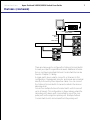
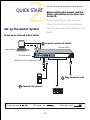
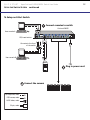
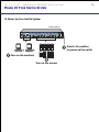
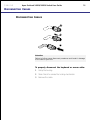
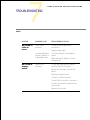
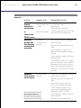
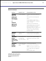
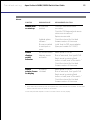
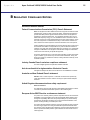
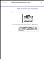
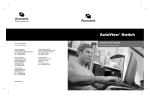
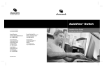
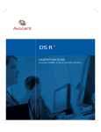
140DX
180DX
OutLook Switch
User Guide
Run Your Servers Smarter
CONTENTS
Apex OutLook 140DX/180DX Switch User Guide
Apex OutLook 140DX/180DX Console
Switch User Guide
© 2000 Apex Inc. All rights reserved.
First Edition June 2000
Printed in the United States of America
Part Number 998-0011-00 Rev. B
The information contained in this guide is
subject to change without notice.
Apex Inc. shall not be liable for technical or
editorial errors or omissions contained herein;
nor is it liable for incidental or consequential
damages resulting from the furnishing,
performance, or use of this material.
Product names mentioned herein may be
trademarks and/or registered trademarks of
their respective companies. PC/AT, PS/2 and
IBM are registered trademarks of International
Business Machines Corporation. Viewpoint,
Viewpoint 64, OutLook and OSCAR are
trademarks of Apex Inc.
Apex Inc.
9911 Willows Road NE
Redmond, WA 98052
USA
Telephone
Fax
Email
Web Site
800 861-5858
425-861-5757
[email protected]
http://www.apex.com
2
CONTENTS
Apex OutLook 140DX/180DX Switch User Guide
SAFETY
Before installing this product, read the Safety Information book.
Antes de instalar este produto, leia o Manual de Informações sobre Segurança.
Pred instalací tohoto produktu si prectete prírucku bezpecnostních instrukcí.
Læs hæftet med sikkerhedsforskrifter, før du installerer dette produkt.
Lue Safety Information -kirjanen, ennen kuin asennat tämän tuotteen.
Avant de procéder à l'installation de ce produit, lisez le manuel Safety Information.
Vor Beginn der Installation die Broschüre mit Sicherheitshinweisen lesen.
Przed zainstalowaniem tego produktu należy przeczytać broszurę Informacje Dotyczące
Bezpieczeństwa.
Prima di installare questo prodotto, leggere l'opuscolo contenente le informazioni
sulla sicurezza.
3
CONTENTS
Apex OutLook 140DX/180DX Switch User Guide
SAFETY ( CONTINUED)
Lees voordat u dit product installeert eerst het boekje met veiligheidsvoorschriften.
Les heftet om sikkerhetsinformasjon (Safety Information) før du installerer dette
produktet.
Antes de instalar este produto, leia o folheto Informações sobre Segurança.
Перед установкой продукта прочтите брошюру по технике безопасности
(Safety Information).
Pred inštaláciou tohto produktu si pre ítajte Informa nú brožúrku o bezpe nosti.
Preden namestite ta izdelek, preberite knjižico Varnostne informacije.
Antes de instalar este producto, lea la Información de Seguridad.
Läs säkerhetsinformationen innan du installerar den här produkten.
Installálás el tt olvassa el a Biztonsági el írások kézikönyvét !
4
CONTENTS
Apex OutLook 140DX/180DX Switch User Guide
GETTING H ELP , SERVICE ,
5
AND I NFORMATION
Getting help, service, and information
If you need help, service, technical assistance, or just
want more information about IBM products, you will
find a wide variety of sources available from IBM to
assist you.
On the World Wide Web, the IBM Personal Computing
Web site has up-to-date information about IBM
Personal Computer products and support.
Some helpful addresses are:
With the original purchase of an IBM hardware product,
you have access to extensive support coverage. During
the IBM hardware product warranty period, you may
call the IBM Personal Computer HelpCenter (1-800772-2227 in the U.S.) for hardware product assistance
covered under the terms of the IBM Statement of
Limited Warranty.
Table 1. IBM Personal Computing Web sites
The following services are available during the warranty
period:
http://www.ibm.com/pc
IBM Personal Computing
• Problem Determination - Trained personnel are
available to assist you with determining if you have
a hardware problem and deciding what action is
necessary to fix the problem.
• IBM Hardware Repair - If the problem is determined
to be caused by IBM hardware under warranty,
trained service personnel are available to provide
the applicable level of service.
World Wide Web site URL Description
http://www.ibm.com
Main IBM home page
http://www.ibm.com/pc/support
IBM Personal Computing Support
http://www.ibm.com/pc/us/accessories
Options by IBM (U.S.)
http://www.ibm.com/pc/us/netfinity
IBM Netfinity Servers (U.S.)
• Engineering Change Management - Occasionally,
there might be changes that are required after a
product has been sold. IBM or your reseller, if
authorized by IBM, will make Engineering Changes
(ECs) available that apply to your hardware.
http://www.ibm.com/pc/techconnect
IBM TechConnect
Be sure to retain your proof of purchase to obtain
warranty service. Refer to the IBM hardware warranty
for a full explanation of IBM’s warranty terms.
You can select a country-specific Web site from these
pages.
Please have the following information ready when you
call:
• Machine type and model
• Serial numbers of your IBM hardware products
• Description of the problem
• Exact wording of any error messages
• Hardware and software configuration information
If you select Profile from the support page, you can
create a customized support page that is specific to
your hardware, complete with Frequently Asked
Questions, Parts Information, Technical Hints and Tips,
and Downloadable Files. You will have the information
you need, all in one place. In addition, you can choose
to receive e-mail notifications whenever new information becomes available about your registered products.
You can also access online support forums, which are
community sites monitored by IBM support staff.
CONTENTS
Apex OutLook 140DX/180DX Switch User Guide
CONTENTS
Safety ............................................................. 3
Getting Help ................................................... 5
1
OVERVIEW .................................................. 8
Product Overview ........................................... 8
Features ........................................................... 9
2
QUICK START ............................................ 11
3
RACK INSTALLATION .............................. 14
4
CABLING .................................................. 15
Cable Lengths ............................................... 15
Cable Locking Mechanism ............................ 15
Disconnecting Cables ................................... 16
Connecting Cables ....................................... 17
Starting the Switch Box ................................ 20
Powering Up the System ............................... 20
Starting the Computers ................................ 21
Configuring the Switch Box .......................... 21
Unattended Reboot ...................................... 22
Resetting the Unit ......................................... 22
Making Connections Under Power ............... 23
Alternative Configurations ............................ 24
5
USING OSCAR .......................................... 26
Launching OSCAR ........................................ 26
OSCAR Selection Screen ............................... 27
OSCAR Status Port Symbols .......................... 28
6
CONTENTS
Apex OutLook 140DX/180DX Switch User Guide
CONTENTS ( CONTINUED)
Command Summary ...................................... 29
OSCAR Advanced Menus Screen .................. 30
Selecting Computers .................................... 31
Switching Tiered Systems ............................. 32
Assigning Unique Names to Computers ........ 33
Changing Menu Attributes ........................... 35
Changing Status Flag Attributes ................... 37
Values and Effects of
Settings on Flag Appearance ........................ 38
Scanning the Computers .............................. 39
Broadcasting Commands .............................. 42
Securing Server Access ................................. 46
Displaying Version Information ..................... 50
Saving the Hardware Settings ....................... 51
Resetting the Mouse and Keyboard .............. 52
Assigning Specific Device Types .................... 53
Capturing the Screen ..................................... 54
6
UPDATING THE FIRMWARE ..................... 55
7
TROUBLESHOOTING ................................. 57
APPENDICES ............................................ 63
A Specifications ............................................ 63
B Regulatory Compliance Notices ................. 65
C Power Cord Set Requirements ................... 66
7
1
OVERVIEW
APEX OUTLOOK SWITCH USER GUIDE
Product Overview
Features
PRODUCT OVERVIEW
The Apex OutLook Console Switch enables you to control
large computer networks using a single keyboard, monitor,
and mouse. On a single video screen, you can select from
as many as 64 computers running different operating
systems.
The 140DX supports 4 computers and one user, while the
180DX supports 8 computers and one user. Both 4 and 8
port switches use the OSCAR on-screen display (OSD)
interface, which has intuitive menus for accessing each
attached computer. Computers can be identified by name
or number, enabling you to view and select server names
that make sense to you.
A typical Apex OutLook Console Switch, also known as
keyboard/monitor mouse (KMM) or keyboard/video/mouse
(KVM) configuration, consists of the console (monitor,
keyboard, and mouse), the switch unit, and the attached
computers.
Additional OutLook Console Switches can be connected to
the primary switch, called tiering, to increase computer
access from 4 computers to as many as 64 computers.
Tiering allows you to modify your OutLook Console Switch
system as your network system needs change.
To switch between computers, type a command at the
keyboard. The selected computer receives typed characters
and displays its video output on the monitor. You can also
use the mouse to interact with the graphic interface of the
selected computer.
Introduction
Apex OutLook 140DX/180DX Switch User Guide
9
F EATURES
F EATURES
You can use the OutLook Console Switch in various configurations to connect from 4 to 64 servers.
The features of the OutLook Console Switch include:
!
OSCAR – Displays system-related information on the monitor, such as power-up test data and configuration menus.
!
Programmable scanning – Evaluates system performance by
sequentially scanning any or all of the computers in the
system. Programmable scanning allows you to determine
which computers to include as well as the duration of the
connection.
!
Configuration non-volatile memory (NVM) – Makes it easy
to set configuration information using commands entered
from the keyboard. The NVM stores the resulting configuration until you decide to change the information, even if the
unit loses power.
!
PS/2 device reset switch – Resets the unit without interrupting power to the system if the keyboard or mouse communication is disrupted.
!
Password protection – Protects against unauthorized users by
providing a password option for security purposes.
!
Switch firmware update – Allows quick and easy update
since the application code of the switch resides in NVM. The
port communications settings are automatically configured to
allow direct downloading from the connected computer.
Introduction
1
Apex OutLook 140DX/180DX Switch User Guide
FEATURES (CONTINUED )
Primary Switch
Keyboard,
Mouse,
and
Video Cables
Secondary Switch
HYDR-002.EPS
There are many ways to configure the OutLook Console Switch
to meet your specific organizational needs. Additional information on configuring multiple OutLook Console Switches can be
found in Chapter 4, Cabling.
A single switch box is used to connect 4 or 8 servers. In this
configuration, the keyboard, monitor, and mouse are connected
directly to the unit by their respective cables. You can connect
the OutLook Console Switch to servers located in the same or
adjoining racks.
You can tier multiple OutLook Console Switch units to connect
up to 64 servers. This configuration is shown above, where the
secondary unit’s device port is connected to one of the computer ports on the original or primary unit. Multiple OutLook
Console Switch units can be tiered from the primary unit.
2
APEX OUTLOOK SWITCH USER GUIDE
QUICK START
Before installing this product, read the
Safety Information on the Apex User
Guide CD.
Get up and running in a few easy steps.
Follow the steps shown in the illustrations.
Select the appropriate setup method for your
Set up the Switch System
switch.
To Set up an OutLook 4-Port Switch
Connect console to switch
OutLook 140DX
User console A
PS/2 reset button
DB9 serial port for updating firmware
Plug in power cord
6
Connect the servers
PS/2 keyboard, male
PS/2 mouse, male
11
HD15 video, male
Q U I C K S TA R T
S ETUP
THE
12
Apex OutLook 140DX/180DX Switch User Guide
S WITCH S YSTEM
continued
To Setup an 8-Port Switch
Connect consoles to switch
OutLook 280ES
User console A
PS/2 reset button
Connects to the front
of the switch
User console B
Plug in power cord
Connect the servers
PS/2 keyboard, male
PS/2 mouse, male
HD15 video, male
50-pin, male
6
Q U I C K S TA R T
Apex OutLook 140DX/180DX Switch User Guide
13
POWER UP Y OUR SWITCH S YSTEM
To Power Up Your Switch System
Primary switch
Press to On position
to power up the switch
Turn on the monitors
Turn on the servers
3
APEX OUTLOOK SWITCH USER GUIDE
INSTALLATION
RACK INSTALLATION
Before installing this product, read the Safety
Information on the Apex User Guide CD.
Refer to the IBM installation instructions for
installation of the console switch in a rack
cabinet.
4
CABLING
APEX OUTLOOK SWITCH USER GUIDE
Cables Lengths/Locking Mechanism
Connecting and Disconnecting Cables
Starting the Switch Box and the Computers
Unattended Reboot
Making Connections Under Power
Alternative Configurations
CABLE L ENGTHS
Cable length affects video quality as well as keyboard and
mouse data timing. The maximum cable length is determined in
part by the computer and peripherals used. Not all systems give
satisfactory results at the maximum length.
USING LOCKING CABLE C ONNECTORS
Keyboard and mouse connectors on the switch work with cables
that have a locking mechanism. The locking mechanism automatically locks cable in place. The cable lock prevents cables
from becoming disconnected from the switch connectors due to
the weight of the cable bundles or accidental tension from
handling cables.
CABLING
Apex OutLook 140DX/180DX Switch User Guide
16
D ISCONNECTING CABLES
D ISCONNECTING CABLES
1
2
3
Attention
Failure to follow proper disconnect procedures could result in damage
to the cable or your unit.
To properly disconnect the keyboard or mouse cable:
1
Grasp the housing.
2
Slide it back to release the locking mechanism.
3
Remove the cable.
CABLING
Apex OutLook 140DX/180DX Switch User Guide
17
CONNECTING C ABLES
CONNECTING CABLES
Connecting the Keyboard Cable in the Proper
Sequence
When you are connecting the video, PS/2 mouse and keyboard
cables from your servers to the OutLook switch, always connect
the keyboard cable after the mouse cable. The switch
detects the system power of the secondary switch or server
through the keyboard cable. When the keyboard cable is connected after the mouse cable, the switch initializes both the
keyboard and mouse interfaces to the system. When the recommended sequence is followed, you can add a new switch or
replace a failed switch without having to restart the system.
Whenever you make changes to the switch system, you should
save the hardware configuration settings. If you do not save the
settings, they are lost when power is lost or turned off. To
reestablish keyboard and mouse communication to the switch,
you might have to reboot each computer. To save your hardware
settings, select the Snapshot command from the OSCAR Advanced menu. See Chapter 5 for additional information on using
OSCAR.
CABLING
Apex OutLook 140DX/180DX Switch User Guide
CONNECTING C ABLES (CONTINUED)
STATEMENT 1
DANGER
Electrical current from power, telephone, and communication
cables is hazardous.
To avoid a shock hazard:
– Do not connect or disconnect any cables or perform
installation, maintenance, or reconfiguration of this product
during an electrical storm.
– Connect all power cords to a properly wired and grounded
electrical outlet.
– Connect to properly wired outlets any equipment that will be
attached to this product.
– When possible, use one hand only to connect or disconnect
signal cables.
– Never turn on any equipment when there is evidence of fire,
water, or structural damage.
– Disconnect the attached power cords, telecommunications
systems, networks, and modems before you open the device
covers, unless instructed otherwise in the installation and
configuration procedures.
– Connect and disconnect cables as described in the following
table when installing, moving, or opening covers on this
product or attached devices.
To Connect:
To Disconnect:
1. Turn everything OFF.
1. Turn everything OFF.
2. First, attach all cables to devices.
2. First, remove power cords from outlet.
3. Attach signal cables to connectors.
3. Remove signal cables from connectors.
4. Attach power cords to outlet.
4. Remove all cables from devices.
5. Turn device ON.
18
CABLING
Apex OutLook 140DX/180DX Switch User Guide
19
CONNECTING C ABLES (CONTINUED)
Connecting the Cables
Figures 1 and 2 show the location of the keyboard, monitor and
mouse ports for each of the switch boxes.
Figure 1. 4-Port connectors
Figure 2. 8-Port connectors
To connect cables:
1
Connect the mouse, keyboard, and video cables to the
appropriate switch connectors. Note that all keyboard and
mouse cables are 6-pin mini-DIN PS/2 style, and all the video
cables are 15-pin VGA/SVGA style. (These connectors are
located on the left rear of each of the switch boxes.)
2
Decide which computer is to be connected to port 1. Connect
the computer’s mouse to the appropriate connector beneath
the port labeled 1. Connect the computer’s keyboard to the
appropriate connector. Connect the computer’s monitor to the
15-pin VGA connector. Bundle and label the cables for easy
identification.
3
Repeat step 2 for all remaining computers to be connected to
the switch box.
4
Connect the power cord to the switch box.
CABLING
Apex OutLook 140DX/180DX Switch User Guide
20
STARTING THE S WITCH BOX
STARTING THE S WITCH BOX
It is important to turn on the switch box before turning on the
computers because when the servers boot up, their drivers send
device settings to the switch.
POWERING UP THE SYSTEM
To power up the system:
1
Press the power switch located on the rear panel of the
switch box to the on (1) position.
2
Power up the computers. During startup, the switch box unit
does the following:
!
Identifies the mouse and keyboard and puts them into
default states
!
Switches to port 1 by default, and displays the number “1”
in the status flag displayed on the monitor. If the status flag
default setting has been changed to Names mode, the
status flag displays the port name instead of the port number. If a status flag is not shown on the monitor, make sure
the computer is connected and powered up.
CABLING
Apex OutLook 140DX/180DX Switch User Guide
21
STARTING THE COMPUTERS
STARTING THE COMPUTERS
During startup, the computers send device settings to the switch
box. The unit then generates standard responses to these
commands and allows the computers to boot successfully
without being physically connected to the keyboard, monitor, or
mouse. As the switch generates these responses, it determines
the appropriate settings for each computer. Once the switch is
installed, you can save these settings to non-volatile memory
(NVM) using the Snapshot command in the OSCAR Advanced
menu. See Chapter 5, Using OSCAR for additional information.
CONFIGURING THE S WITCH B OX
When you first turn on the switch box, no configuration is
needed for basic switching operation (see Chapter 5). To configure the unit to meet your specific needs, such as assigning
unique names for the computers or displaying the computers by
their assigned names or port numbers, see Chapter 5, Using
OSCAR.
CABLING
Apex OutLook 140DX/180DX Switch User Guide
22
UNATTENDED REBOOT
UNATTENDED REBOOT
After a power outage, each server connected to the switch box
reboots (if configured to do so) when power returns without
operator intervention. The switch generates responses to ensure
that the reboot is successful and that it is ready to switch between computers.
Note
This procedure requires that the Snapshot command be performed
before power loss.
RESETTING THE UNIT
If the keyboard or mouse locks up, you can push the RESET
button on the back panel to reset the switch. Pressing the RESET
button may allow you to recover the device settings without
power cycling the computers.
CABLING
Apex OutLook 140DX/180DX Switch User Guide
23
MAKING C ONNECTIONS U NDER POWER
MAKING CONNECTIONS UNDER POWER
You can connect additional computers to the switch while it is
powered up. When you power up the newly connected computers, the switch recognizes them, and you can switch to the new
computers without taking any additional steps.
You can also connect the mouse and/or keyboard to the switch
while the system is powered up. When you connect a new
device, the switch recognizes it and configures it to the settings
of the currently selected computer. This technique allows failed
devices to be replaced without having to restart the system.
Note
When new computers are added to the switch, or when existing
connections are changed, the new configurations should be saved in
NVM by using the Snapshot command on the OSCAR Advanced
menu. (See Chapter 5, Using OSCAR.)
CABLING
Apex OutLook 140DX/180DX Switch User Guide
24
A LTERNATIVE C ONFIGURATIONS
A LTERNATIVE C ONFIGURATIONS
Primary
Secondary
There are other ways to configure your system, such as the
tiered switch configuration.
Tiered Switch Configuration
In tiered systems, you can connect additional switches to ports
on a primary unit. That is, switches can be tiered in primary/
secondary configurations to allow one primary switch to switch
between computers or other switch units.
Tiering involves linking the secondary units’ physical keyboard,
mouse, and monitor connections to one of the computer ports on
the primary unit. For example, one eight-port primary unit can
accommodate eight secondary switch units. A system with eight
servers connected to each of the eight secondary switches would
provide a 1x64 configuration.
An example of a tiered switch configuration is shown above.
When connecting a secondary unit to one of the ports of the
master unit, you need to indicate this connection to the primary
unit by performing the Assigning Specific Device Types procedure
described in Chapter 5, Using OSCAR, entering the secondary
unit designation for the associated port number instead of a
monitor type. OSCAR allows secondary ports to be treated much
like ports on the primary switch. It may be helpful to name each
secondary unit as described in Assigning Unique Names to
Computers in Chapter 5.
CABLING
Apex OutLook 140DX/180DX Switch User Guide
25
A LTERNATIVE CONFIGURATIONS (CONTINUED )
Connecting Tiers while the System is Powered Up
If necessary, you can connect a primary unit to a secondary unit
while the system is powered up. This technique can be used to
isolate any problems with minimum disruption to the system.
When plugging a primary switch box into a secondary unit, first
connect the mouse and keyboard cables, and then connect the
video cable. This is important because the primary unit interprets
the keyboard connection as the secondary unit’s power up. At
this point, the primary unit sends initialization codes to the
secondary unit, triggering device configuration.
See Chapter 5, Using OSCAR, for information on switching
tiered systems.
5
APEX OUTLOOK SWITCH USER GUIDE
USING OSCAR
Launching OSCAR
OSCAR Status Port Symbols and Advanced Menus
Selecting Computers and Switching Tiered Systems
Assigning Unique Names and Device Types
Changing Menu and Status Flag Attributes
Scanning the Computers and Broadcasting Commands
Securing Server Access
LAUNCHING OSCAR
Press PRINT SCRN to access the keyboard/monitor/mouse OSCAR
menus.
OSCAR Selection Screen
When you press the PRINT SCRN key to open OSCAR menus, the
first screen that appears is called OSCAR Selection. Basic functions such as selecting computers and checking port/computer
status are performed from the Selection screen.
The Selection screen lists all the ports in the system, the associated computer names, and the status of each port. It can be
organized either by port number or by computer name. To
identify your computers by name, see Assigning Unique Names
to Computers in this chapter. To change the order in which
computers are listed, see Changing Menu Attributes. On large
systems, you may need to use the ARROW keys or the PAGE
DOWN key to scroll through the list of ports.
USING OSCAR
Apex OutLook 140DX/180DX Switch User Guide
OSCAR SELECTION S CREEN
To open OSCAR or to access OSCAR
Selection Screen on a primary switch
1
Press PRINT SCRN.
To open OSCAR or to access OSCAR
Selection Screen on a secondary switch
1
Press PRINT SCRN to access OSCAR Selection
screen at the primary switch.
2
Highlight the number of the port you want to
access and press ENTER.
3
Press PRINT SCRN twice. The OSCAR Selection
screen at the secondary switch appears.
The factory defaults for OSCAR should not be
changed in a secondary switch because adjustments can cause conflicts between the secondary
and the primary switch.
Note
If the factory settings have been changed, you can
restore them by selecting <F10> from your keyboard.
27
USING OSCAR
Apex OutLook 140DX/180DX Switch User Guide
28
OSCAR STATUS PORT SYMBOLS
OSCAR S TATUS PORT S YMBOLS
+
Indicates computer connected and running
X
Denotes Secondary switch connected and running
A
Identifies the user console connected to the server.
Note
OSCAR screens in this document are
examples. Your screens may vary depending on your configuration.
USING OSCAR
Apex OutLook 140DX/180DX Switch User Guide
29
COMMAND SUMMARY
COMMAND SUMMARY
This section describes the key sequences that are used to activate OSCAR functions.
Apex OutLook Console Switch OSCAR OSD Keyboard Sequences
Print Scrn
Pressing once activates OSCAR (ON Screen Configuration and
Activity Reporting), immediate double entry sends the print
screen command to the selected computer or secondary switch.
ESCAPE
Terminates the command or selection without executing
ENTER
Executes the current selection, command, or submenu.
UP ARROW
Moves up one field or up one item in the menu
DOWN ARROW
Moves down one field or down one item in the menu
RIGHT ARROW or TAB
Moves one field to the right, wraps downward or highlights
LEFT ARROW or SHIFT+TAB
Moves one field to the left, wraps upward or highlights
adjacent menu
+
Increases the current field value
-
Decreases the current field value
PAGE UP
Displays the previous screen of a list
PAGE DOWN
Displays the next screen of a list
HOME
Displays the top screen of a list
END
Displays the bottom screen of a list
USING OSCAR
Apex OutLook 140DX/180DX Switch User Guide
30
OSCAR ADVANCED MENU SCREEN
OSCAR A DVANCED MENUS S CREEN
All commands other than selecting computers are performed
from OSCAR Advanced Menus. The Advanced Menus screen
contains two menus. The Commands menu shows the commands
that cause an action to take place. The Setup menu shows menu
screens to set configurations.
Opening OSCAR Advanced Menus
1
Press PRINT SCRN to open OSCAR Selection.
2
Press F2.
The OSCAR Advanced Menus screen appears showing the
commands listed under the Commands menu. Highlighting Setup
shows screen selections available for configuring your switch.
Moving the highlight with the ARROW keys or mouse in either
menu selects a specific command or menu screen.
Exiting OSCAR
!
To exit OSCAR, press ESC.
USING OSCAR
Apex OutLook 140DX/180DX Switch User Guide
31
SELECTING C OMPUTERS
SELECTING COMPUTERS
Use OSCAR menus to switch computers, that is, to select which
computer receives commands from and displays output to the
console. When you select a computer, the switch reconfigures
the keyboard and mouse for the selected computer using the
settings stored in its memory. The current information (for
example, the state of the Caps Lock key) is maintained for each
computer in the system. When configuration is complete, the
video output of the selected computer passes to the monitor and
subsequent keystrokes or mouse movement are relayed to the
connected system.
1
If your computers are ordered by the number of the port, in
OSCAR Selection screen, type the port number of the
computer you want to switch to.
—or—
Use the ARROW keys or mouse to select a computer.
—or—
If your computers are ordered by name, type the first letters
of the computer name to establish it as unique in order to
select it. To identify computers by name, see Assigning
Unique Names to Computers.
2
Press ENTER.
3
When you are finished switching, press ESC to exit OSCAR
and remove OSCAR menus from your monitor display. If the
status flag is enabled, it remains displayed to indicate the
currently selected computer.
USING OSCAR
Apex OutLook 140DX/180DX Switch User Guide
32
SWITCHING T IERED SYSTEMS
SWITCHING T IERED S YSTEMS
To switch the Keyboard/Monitor/Mouse Switch Box to a computer that is connected to the primary through a secondary unit,
proceed as follows:
1
Press PRINT SCRN. The OSCAR appears on the monitor.
2
Type the number of the port to which the slave unit is
connected followed by a dash and the number of the port
(on the secondary unit) to which the computer is connected.
For example, to switch to the computer connected to port 3
of a secondary unit connected to port 1 of the primary, press
PRINT SCRN and then type 1, -, 1.
Note
To work properly, both primary and secondary must be ordered by
port number. See Changing Menu Attributes on page 39.
3
Press ENTER.
USING OSCAR
Apex OutLook 140DX/180DX Switch User Guide
33
ASSIGNING UNIQUE N AMES TO COMPUTERS
A SSIGNING U NIQUE NAMES TO COMPUTERS
You may find it easier to identify the computers in a system by
name rather than by port number. For example, in a network
environment, you can assign the same names to each computer
as those assigned by the network. To list the computers by name
in OSCAR menus, see Changing Menu Attributes.
Note
Before you can assign names to computers attached to a secondary
switch, you must first associate the secondary device with a port. See
the section Assigning Specific Device Types.
To assign unique names to computers:
1
In the Advanced Menus screen, highlight the Setup menu.
2
Highlight Names and press ENTER; the Port Name Setup
screen appears.
3
Using the up and down arrow keys, select the port number
for which you want to enter or change a computer name.
4
Type a name for the computer and press ENTER. Computer
names may be up to 12 characters long, including only A-Z,
0-9, the space and the dash character. Lowercase letters are
converted to uppercase. Press BACKSPACE to delete an
incorrect entry.
USING OSCAR
Apex OutLook 140DX/180DX Switch User Guide
34
ASSIGNING UNIQUE N AMES TO C OMPUTERS (CONTINUED)
Note: Port numbering scheme
After you have specified a device type, the port numbering structure is
reorganized so that the secondary ports display in OSCAR. Secondary
ports have a different numbering scheme from the primary switch
ports:
Primary port numbers:
Port 1, Port 2, Port 3, etc
Secondary port numbers:
Port 3-1, Port 3-2, Port 3-3, etc.
For Port 3-1, 3 indicates the number of the port on the primary switch
and 1 is the number of the port on the secondary switch.
For more information, see “Devices Dialog Box” in the section
Operation and Configuration.
To identify servers by name, see “Names Dialog Box” in the section
Operation and Configuration.
5
If necessary, repeat steps 3 and 4 for each computer in the
system.
6
Press ENTER to save the changes and exit the menu.
—or—
Press F10 to restore the default settings.
—or—
Press ESC to exit the menu without saving the changes.
USING OSCAR
Apex OutLook 140DX/180DX Switch User Guide
35
CHANGING MENU ATTRIBUTES
CHANGING MENU A TTRIBUTES
On the OSCAR Attributes screen, you can change the display
order of computer ports to port number or port name. Other
attributes of OSCAR screens, such as the position and color, can
be changed to suit the particular needs of the user.
To change menu attributes:
1
On the Advanced Menus screen, highlight the Setup menu.
2
Highlight OSCAR and press ENTER. The OSCAR Attributes
screen appears.
3
Highlight the settings you want to change and use the + or –
key to obtain the desired value.
As you select different values, the effect of the changes is
reflected immediately on the display. The table, Screen
Appearance Settings, describes each of the available menu
attributes.
Note
While changing OSCAR attributes, it is possible to scramble the
menu and screens, making it difficult to correct the problem. If
this occurs, reset the switch to its default OSCAR values by
pressing: ESC + ESC + PRINT SCRN + F10 + Y + ENTER
4
Press ESC to save the settings and exit the menu.
—or—
Press F10 to restore default settings.
—or—
Press ESC to exit the menu without saving the settings.
Display of the Selection screen is delayed after PRINT SCRN is
pressed. Increasing delay can prevent the screen from being a
distraction when performing simple computer switching operations.
USING OSCAR
Apex OutLook 140DX/180DX Switch User Guide
36
CHANGING MENU ATTRIBUTES ( CONTINUED)
Screen Appearance Settings
TO CHANGE…
SELECT…
VALUES
Size of screen
Resolution
Select 384 or 768—the lower the
value, the larger the size.
Size of text
Height
Higher values display larger text.
Location of screen
Horizontal
0-127
Vertical
0-255
Background
0-7
Highlight
0-7
Text
0-7
Timing of OSCAR
Delay Time
Time in seconds the Selection screen
is delayed before appearing after
display Print Scrn is pressed. (0-60)
Increasing delay can prevent the
screen from being a distraction when
performing simple computer
switching operations.
Order of computers
Order
Choose to list computers numerically
by port number or alphabetically by
name.
Color of screen and text
USING OSCAR
Apex OutLook 140DX/180DX Switch User Guide
37
CHANGING STATUS FLAG ATTRIBUTES
CHANGING STATUS F LAG A TTRIBUTES
The status flag indicates the name or port number of the currently selected computer. You can choose to display the status
flag at all times, for a few seconds after switching, or not at all.
You can also change the color of the status flag and its location
on the screen.
To change status flag attributes:
1
On the Advanced Menus screen, highlight the Setup menu.
2
Highlight Flag and press ENTER. The Flag Configuration screen
appears.
3
Highlight the settings you want to change and use the + or –
key to adjust the values. The Flag Appearance Settings table
on the following page describes each of the available menu
attributes.
4
Press ESC to save the settings and exit the menu.
—or—
Press F10 to restore default settings.
—or—
Press ESC to exit the menu without saving the settings.
USING OSCAR
Apex OutLook 140DX/180DX Switch User Guide
CHANGING STATUS FLAG A TTRIBUTES (CONTINUED )
VALUES AND EFFECTS OF S ETTINGS ON FLAG APPEARANCE
Flag Appearance Settings
SETTING
VALUES
EFFECT
Enabled
Flag Off
Flag does not appear.
Ports On
Flag always on, indicating selected port number.
Names On
Flag always on, indicating selected computer by name.
Ports Timed
Port number appears for five seconds after switching.
Names Timed
Name appears for five seconds after switching.
Row
0-14
Positions the flag vertically on the screen.
Column
0-25
Positions the flag horizontally on the screen.
Color
0-7
Sets the flag color.
Text
0-7
Sets the flag text color.
38
USING OSCAR
Apex OutLook 140DX/180DX Switch User Guide
39
SCANNING THE C OMPUTERS
SCANNING THE COMPUTERS
In scan mode, the switch automatically switches from port to
port (computer to computer). You can scan the entire system
sequentially or designate a custom scan pattern by specifying
computers and durations.
Placing the switch in scan mode
To place the switch in scanning mode:
1
From the Commands menu in the Advanced Menus screen,
highlight Scan.
2
Press ENTER.
Canceling scan mode
!
Press any key (except PRINT SCRN) or move the mouse; the
scan stops at the currently selected computer.
USING OSCAR
Apex OutLook 140DX/180DX Switch User Guide
40
SCANNING THE C OMPUTERS ( CONTINUED)
Setting a custom scan pattern
To set a custom scan pattern:
1
In the Advanced Menus screen, highlight the Setup menu.
2
Highlight Scan and press ENTER. The Scan Pattern Setup
screen appears with the first port position (or computer
name) highlighted.
3
Type the port number of the first computer to be included in
the scan.
—or—
If your computers are listed by name, type the first few
letters of the name of the first computer to be included in
the scan.
4
Highlight the Sec column, and then type the number of
seconds you want this computer to be selected before
switching to the next computer in the sequence.
5
Highlight the next line and repeat steps 3 and 4 for each of
the remaining computers.
6
Press ENTER to save the settings and exit the menu. The new
scan pattern replaces the standard or previous custom scan
pattern.
—or—
Press F10 to restore default settings.
—or—
Press ESC to exit the menu without saving the settings.
USING OSCAR
Apex OutLook 140DX/180DX Switch User Guide
41
SCANNING THE C OMPUTERS ( CONTINUED)
Removing a computer from the scan list
To remove a computer from the scan list:
1
On the Scan Pattern Setup screen, type the port number of
the computer to be removed.
—or—
If your computers are listed by name, type the first few
letters of the name of the computer.
2
Highlight the Sec column.
3
Type 0 for the number of seconds.
Press DELETE while on the Scan Pattern Setup screen to
delete the highlighted computer and all entries below it.
4
Press ENTER to save the settings and exit the menu. The new
scan pattern replaces the standard or previous custom scan
pattern.
—or—
Press F10 to restore default settings.
—or—
Press ESC to exit the menu without saving the settings.
USING OSCAR
Apex OutLook 140DX/180DX Switch User Guide
42
BROADCASTING C OMMANDS
BROADCASTING COMMANDS
Broadcasting enables you to simultaneously control more than
one computer in a system. This feature is useful when you want
to ensure that all selected computers receive identical input. For
each computer receiving the broadcast, you can choose to
broadcast keystrokes and/or mouse movements independently.
Note
The keyboard state must be identical for all servers receiving a
broadcast to interpret keystrokes identically. Specifically, the CAPS
LOCK and NUMLOCK modes must be the same on all keyboards. While
the switch attempts to send keystrokes to the selected servers simultaneously, some servers may inhibit and thereby delay the transmission.
Note
For the mouse to work accurately, all systems must have identical
mouse drivers, desktops (i.e., identically placed icons), and video
resolutions. In addition, the mouse must be in exactly the same place
on all screens. Because these conditions are extremely difficult to
achieve, broadcasting mouse movements to multiple systems may
have unpredictable results.
To broadcast to selected computers:
1
From the Setup menu in the Advanced Menus screen,
highlight Broadcast and press ENTER; the Broadcast Settings
menu appears.
2
For each port select which computers receive keyboard and/
or mouse commands by using the + or – key to choose YES
or NO.
3
Press ENTER to save the settings.
4
From the Commands menu in the Advanced Menus screen,
highlight Broadcast. Press ENTER to turn on the broadcast
mode. Type information and/or make mouse movements you
want to broadcast.
USING OSCAR
Apex OutLook 140DX/180DX Switch User Guide
43
BROADCASTING C OMMANDS (CONTINUED)
To turn off the broadcast mode:
1
From the Commands menu in the Advanced
Menus, highlight Broadcast and press ENTER.
Broadcasting to Tiered Configurations
In a tiered system you can broadcast to any
combination of computers on the entire system.
USING OSCAR
Apex OutLook 140DX/180DX Switch User Guide
44
BROADCASTING C OMMANDS (CONTINUED)
To broadcast to tiered configurations:
1
From the OSCAR Selection screen at the primary switch,
highlight the port number of the secondary switch (for
example, Port 1-1, 2-1, 3-1, etc) to which you want to
broadcast commands; press ENTER.
2
Press PRINT SCREEN twice; the OSCAR Selection screen of the
secondary switch appears. Press F2 to access the Advanced
Menus screen.
3
From the Setup menu, highlight Broadcast. Press ENTER to
access the Broadcast Settings menu.
4
For each port select which computers receive keyboard and/
or mouse commands by using the + or – key to choose YES
or NO.
5
Press ENTER to save the settings.
6
Press PRINT SCREEN once to access the primary switch.
7
Repeat steps 1–6 to send broadcast commands to computers
attached to additional secondary switches.
8
From the Setup menu in the Advanced Menus at the primary
switch, highlight Broadcast. Press ENTER; the Broadcast
Settings menu appears.
9
For each port select which computers receive keyboard and/
or mouse commands by using the + or – key to choose YES
or NO.
10 Press ENTER to save the settings.
11 From the Commands menu in the Advanced Menus screen at
the primary switch, highlight Broadcast. Press ENTER to turn
on the broadcast mode.
12 From the OSCAR Selection screen at the primary switch,
highlight the port number of the secondary switch for which
you want to broadcast commands; press ENTER.
13 Press PRINT SCREEN twice; then press F2. From the Commands menu in the Advanced Menus screen highlight
Broadcast, then press ENTER to turn on the broadcast mode
on the secondary switch.
USING OSCAR
Apex OutLook 140DX/180DX Switch User Guide
45
BROADCASTING C OMMANDS (CONTINUED)
14 From a computer attached to the primary switch and con-
nected to the secondary switch, type information and/or
make mouse movements you want to broadcast.
Note
Broadcast only to systems directly connected to a primary OutLook
switch or only to secondary OutLook switches connected to a primary
OutLook switch.
To turn off broadcast mode for a tiered configuration:
1
From the Commands menu in the Advanced Menus screen at
the primary switch, highlight Broadcast. Press ENTER to turn
off the broadcast mode.
2
From the OSCAR Selection screen at the primary switch,
highlight the port number of the secondary switch for which
you want to stop broadcasting commands; press ENTER.
3
Press PRINT SCREEN twice; then press F2. From the Commands
menu in the Advanced Menus screen highlight Broadcast,
then press ENTER to turn off the broadcast mode on the
secondary switch.
USING OSCAR
Apex OutLook 140DX/180DX Switch User Guide
46
SECURING SERVER A CCESS
SECURING S ERVER ACCESS
Advanced server applications should be protected against
unauthorized users. The switch security feature enables you to
lock the keyboard and monitor, requiring you to type a password
before resuming operation. You can also set a time delay before
the system is locked.
You must always provide a password to access the fields in the
Security Configuration screen. After you type the correct password, the other fields on the screen are activated.
Locking the screen and keyboard
To lock the screen and keyboard:
1
On the Advanced Menus screen, highlight the Setup menu.
2
Highlight Security and press ENTER; the Security Configuration screen appears.
3
Type your password and press ENTER.
Passwords can be up to eight characters (case sensitive). You
must enter the new password twice for confirmation.
Note
The factory default password is “OSCAR”. Because the CAPS LOCK
key is disabled by default, you must hold down SHIFT as you type
each letter.
4
Highlight Time Delay and select the number of minutes from
1 to 254 before you want your screen saver to turn on.
Selecting “Off” disables the screen saver.
5
Highlight Mode and select Energy if you are using an Energy
Star-compliant monitor or Screen if your monitor is not of
that type.
Attention
Monitor damage can result from use of Energy Mode with
monitors that are not Energy Star-compliant.
USING OSCAR
Apex OutLook 140DX/180DX Switch User Guide
47
SECURING SERVER A CCESS
6
To enable the screen saver mode, press ENTER either in the
Time Delay or Mode fields.
—or—
Highlight Test and press ENTER to start the screen saver
mode immediately. See the Security Configuration Settings
table below for a description of the settings.
Security Configuration Settings
SETTING
ACTION
Password
Enter current password to activate other fields.
New Password
Type a new password.
Repeat new
Retype new password to confirm it.
Time Delay
Before the screen saver starts, set a value from 1 to 254 minutes or
select OFF.
Mode
Energy
Turns off the monitor. Use only with Energy Star-compliant
monitors that go into lower-power mode when time delay
has elapsed.
Screen
Turns off video when time-only delay has elapsed. Use with
non-Energy Star-compliant monitors.
Test
Immediately activates screen-selected mode.
USING OSCAR
Apex OutLook 140DX/180DX Switch User Guide
48
SECURING SERVER ACCESS ( CONTINUED)
Turning off the Screen Saver
To turn off the screen saver:
1
If you are in screen saver mode, press any key on your
keyboard and then type your password if your console is
password protected.
2
In the Advanced Menus screen, highlight the Setup menu.
3
Highlight Security and press ENTER; the Security Configuration screen appears.
4
Highlight Time Delay and select OFF. Press ENTER.
USING OSCAR
Apex OutLook 140DX/180DX Switch User Guide
49
SECURING SERVER ACCESS ( CONTINUED)
Blanking the Monitor without Locking the Console
To blank the monitor without locking the console:
1
If you are in screen saver mode, press any key on your
keyboard and then type your password if your console is
password protected.
2
In the Advanced Menus screen, highlight the Setup menu.
3
Highlight Security and press ENTER. The Security Configuration screen appears.
4
In the Security Configuration screen, press ENTER twice with
the New Password and Repeat New fields empty.
5
Highlight the settings you want to change and use the + or –
key to adjust values.
6
Highlight Test and press ENTER to start screen saver mode
immediately.
This action overrides the use of a password. Pressing any key on
the keyboard unlocks the console. Your computer will not be
protected against unauthorized users.
Attention
Monitor damage can result from use of Energy Mode with monitors
that are not Energy Star-compliant.
USING OSCAR
Apex OutLook 140DX/180DX Switch User Guide
50
DISPLAYING V ERSION INFORMATION
D ISPLAYING VERSION INFORMATION
To facilitate system troubleshooting and support, you can display
the version number of the switch firmware as well as information
about any auxiliary devices connected to the switch.
The Version screen also displays specific device information for
the currently selected computer, including enabled/ disabled,
typematic rate, LED settings, port mode, and keyboard type for
the keyboard, and enabled/ disabled, sample rate, resolution,
and mouse type for the mouse.
To display version information and device settings:
1
From the Commands menu in the Advanced Menus screen,
move the highlight to Version and press ENTER. The Version
screen appears.
2
To display version information for an auxiliary device, press
F2.
3
Press ESC to close the Version screen.
USING OSCAR
Apex OutLook 140DX/180DX Switch User Guide
51
SAVING THE HARDWARE SETTINGS
SAVING THE HARDWARE SETTINGS
Whenever you add or remove computers to or from the system,
or whenever you change the mouse or monitor, you should save
the hardware settings. If you do not save the settings, they are
lost when power is lost or turned off, and it might be necessary
to reboot each computer to reestablish keyboard and mouse
communication.
To save the hardware settings:
1
From the Commands menu in the Advanced Menus screen,
highlight Snapshot.
2
Press ENTER.
USING OSCAR
Apex OutLook 140DX/180DX Switch User Guide
52
RESETTING THE M OUSE AND KEYBOARD
RESETTING THE MOUSE AND K EYBOARD
If the keyboard or mouse locks up, you may be able to recover
the device settings by resetting the switch. Resetting the mouse
and keyboard attempts to restore the correct settings for the
selected computer.
To reset the mouse and keyboard values:
1
From the Commands menu in the Advanced Menus screen,
highlight Reset and press ENTER.
2
If step 1 does not correct the problem, press the RESET
button on the back panel of the switch.
USING OSCAR
Apex OutLook 140DX/180DX Switch User Guide
53
ASSIGNING SPECIFIC D EVICE T YPES
A SSIGNING S PECIFIC DEVICE T YPES
If your system includes one or more secondary switches in a
tiered configuration, you must make the primary switch aware of
the secondary switches by assigning a specific device type.
To assign a device type:
1
On the Advanced Menus screen, highlight the Setup menu.
2
Highlight Devices and press ENTER; the Device Settings
screen appears.
3
To assign a secondary switch to a port, highlight the port and
use the + or – key to obtain the appropriate values.
4
Press ENTER to save the settings and exit the menu.
—or—
F10 to restore default settings.
—or—
Press ESC to exit the menu without saving the settings.
USING OSCAR
Apex OutLook 140DX/180DX Switch User Guide
54
CAPTURING THE S CREEN
CAPTURING
THE
S CREEN
The OSCAR relies on the PRINT SCRN key for various operations.
If you want to use the PRINT SCRN key to capture the screen,
you will need to press the key various times in order to capture
the screen, depending on your configuration.
To capture the screen using the PRINT SCREEN key:
1
On a computer connected to a primary switch, press PRINT
SCRN twice.
The first keystroke opens OSCAR menus in the primary
switch. The second keystroke clears the screen, and then
captures or prints the screen.
2
On a computer connected to a secondary switch in a tiered
configuration, press PRINT SCRN four times.
The first keystroke displays OSCAR in the primary switch.
The second keystroke displays OSCAR in the secondary
switch. The third keystroke displays both OSCARs. The fourth
keystroke clears the screen, and then captures or prints the
screen.
6
APEX OUTLOOK SWITCH USER GUIDE
UPDATING
FIRMWARE
UPDATING THE FIRMWARE
The Apex Web site has information on this product as well as the latest
drivers and firmware update images. You can access the site at http://
www.apex.com/support/outlook-sup.htm to find updates for your
OutLook product.
You can update the switch firmware; the application code of the switch
resides in NVM, and therefore can be quickly and easily updated. The
port communication settings are automatically configured to allow
direct downloading from the connected computer.
To update the firmware you need the following items:
•
Computer running Windows 95/98
•
Available serial communications port on the computer
•
Standard serial cable (DB-male) that connects between the switch
and the PC computer
•
Firmware update
Firmware
Apex OutLook 140DX/180DX Switch User Guide
56
To update firmware:
1
Connect the standard serial cable to the serial connector on the
PC computer and to the serial connector on the back panel of the
switch.
2
Navigate to the drive where you have saved the firmware update.
3
Double-click to open the file WUpDate.exe.
4
In the dialog box that displays, select the desired language and
COM port.
5
Click Load, then click Done.
6
Once the firmware is updated, the following message displays:
“100% Complete. Download completed successfully. Thank
you for using APEX products.”
7
The switch automatically reboots after the update is completed.
7
APEX OUTLOOK SWITCH USER GUIDE
TROUBLESHOOTING
Video
SYMPTOM
PROBABLE CAUSE
RECOMMENDED SOLUTION
No OSCAR or
video at
server
Video cable
problem
Check for loose video cable
connection.
No OSCAR at
primary
switch
Replace video cable.
Incorrect settings in
Devices, Names, or
Flag dialog boxes
Confirm settings in these dialog
boxes.
Power cord
problem
On the front panel of the switch,
confirm that the LED lights.
Reset settings to default in these
dialog boxes.
Reconnect the power cord to the
switch.
Replace the power cord.
Check AC outlet for power.
Check that the monitor is turned on.
Check the control for brightness on
the monitor.
Replace the monitor.
Tr o u b l e s h o o t i n g
Apex OutLook 140DX/180DX Switch User Guide
Keyboard
SYMPTOM
PROBABLE CAUSE
RECOMMENDED SOLUTION
Console
keyboard is
not working
OSCAR Delay Time
in effect
Turn off Delay Time:
Setup>Menu
Type 0 secs for Delay Time.
or
Defective keyboard
Check to see if the Num Lock, Caps
Lock, and Scroll Lock keys light.
Keyboard or
keyboard cable
problem
Check for loose console keyboard
cable connection.
Cannot start
OSCAR menus
Keyboard
worked, but
then stopped
working with
one server
Replace interconnecting keyboard
cable.*
Check maximum length of the
keyboard cable (maximum length =
12 feet).
Check maximum length of console
cable extension.
Press the Reset button on the back
panel of the switch, which resets all
keyboards and mice on all servers
(must have performed Snapshot in
order for the reset function to work
properly).
Keyboard
never worked
on one server
Keyboard cable
problem
Check for PS/2 keyboard and mouse
cable cross-connections.*
Replace interconnecting keyboard
cable.*
Disconnect and reconnect the
interconnecting keyboard cable.*
*Some servers require restarting
when the keyboard cable is
disconnected from the server. For
this reason, perform these tests
when the server can be restarted.
Check maximum length of the
interconnecting keyboard cable
(maximum length = 12 feet).
Check maximum length of console
cable extension.
Replace the console keyboard.*
58
Apex OutLook 140DX/180DX Switch User Guide
Tr o u b l e s h o o t i n g
Keyboard (continued)
SYMPTOM
PROBABLE CAUSE
RECOMMENDED SOLUTION
Keyboard
signal did
work on all
servers, but
then stopped
Console keyboard
Check for loose console keyboard
cable.
Reconnect the console keyboard
cable.*
Check maximum length of the
console cable extension (maximum
length = 12 feet).
or
Keyboard
signal never
did work on
all servers
Replace the console keyboard.*
Press the Reset button on the back
panel of the switch (must have
performed Snapshot in order for the
reset function to work properly).
Check for loose interconnecting
keyboard cables.
Keyboard
error on
startup
Updated system
software
Check the internet for the latest
firmware version of the keyboard.
Keystrokes
shifted,
swaps upper
case for lower
case
Server keyboard left
in shifted state
when last selected
Press both SHIFT keys to change
keystrokes to lower case or upper
case.
Keystrokes
are not
working
properly
Console keystrokes
stuck in a locked
mode
At the console keyboard:
On the left side of the keyboard,
press
CAPS LOCK+SHIFT+CONTROL+ALT
On the right side of the keyboard,
press
ALT+CONTROL+SHIFT
*Some servers require restarting when
the keyboard cable is disconnected from
the server. For this reason, perform
these tests when the server can be
restarted.
59
Tr o u b l e s h o o t i n g
60
Apex OutLook 140DX/180DX Switch User Guide
Mouse
SYMPTOM
PROBABLE CAUSE
RECOMMENDED SOLUTION
Mouse error
on start-up
Mouse cable
problem
Check for loose mouse cable
connection.
Check for PS/2 keyboard and mouse
1
cable cross-connections.
Replace mouse cable.
Mouse
displays
erratic
behavior
Updated system
software
Check the internet for the latest
firmware version of the mouse.
Mouse connected
to serial port on
server
Install Serial-to-PS/2 mouse adapter
(Apex part number ELC-11KM).
No communication
between mouse
and switch
Reset mouse in OSCAR:
Main>Commands, then type ALT+R.
2
Reset mouse by pressing Reset
2
button on back panel of the switch.
Check the internet for the latest
firmware version of the mouse.
Mouse
pointer frozen
on display
Mouse not
initialized
2
Reset mouse in OSCAR:
Main>Commands, then type ALT+R.
Reset mouse by pressing Reset
2
button on back panel of the switch.
Check the internet for the latest
firmware version of the mouse.
1 Some servers require restarting when the keyboard cable is disconnected from the server. For this reason,
perform these tests when the server can be restarted.
2 Must have performed Snapshot in order for the reset function to work properly.
Tr o u b l e s h o o t i n g
Apex OutLook 140DX/180DX Switch User Guide
61
Switch Behaviors
SYMPTOM
PROBABLE CAUSE
R ECOMMENDED SOLUTI ON
Switch selects
servers at will
Scan mode enabled
Turn off scanning:
Main>Commands, then clear Enabled.
Same
keystrokes or
mouse
movements
display on
one or more
servers
Broadcast mode
activated
Turn off broadcasting:
Main>Commands, then clear
Activiated.
Can only select Incorrect settings in
the Device Modify
Port 1 on a
dialog box at the
secondary
primary switch
switch
(for example,
selecting
Port 1-4 selects
Port 1-1)
Confirm the selection of the correct
number of ports (2, 4, 8, 10) for the
secondary switch:
Main>Setup>Devices>Device Modify
Confirm that all port settings are set to
Standard if connected to servers.
Tr o u b l e s h o o t i n g
Apex OutLook 140DX/180DX Switch User Guide
62
Firmware Update
SYMPTOM
PROBABLE CAUSE
RECOMMENDED SOLUTI ON
Firmware
does not
download
Cable problems
Check for loose cable connections.
Replace serial cable.
Check that the serial cable is connected to
the COM port on the server and to the serial
port on the switch.
Verify that they proper COM port is selected
on the update utility.
Download
timed out
Cannot access port
Confirm that the correct port was selected.
If another program is using the same port,
quit the program.
If a serial cable is not installed, install one. If
it is defective, replace it.
APEX OUTLOOK SWITCH USER GUIDE
APPENDIX
A
S PECIFICATIONS
Apex OutLook Console Switch 4- and 8-Port Specifications
DIMENSIONS
Height
1.7 in (4.3 cm)
Depth
8.0 in (20.3 cm)
Width
17 in (43.2 cm)
Weight
5.25 lbs (2.38 kg)
INPUT POWER REQUIREMENTS
Rated Voltage
100-240V AC
Rated Frequency
50-60 Hz
Rated Input Current
1A maximum
TEMPERATURE RANGE
Maximum Ambient Operating Temperature
50º – 95º F (10º – 35º C )
0 – 3000 Feet (0 – 914 meters)
50º – 90º F (10º – 32º C )
3000 – 7000 feet (914 – 2133 meters)
Ambient Storage and Shipping Temperature
-4º – 140º F (-20º – 60º C)
RELATIVE HUMIDITY (NON-CONDENSING)
Operating
8% – 80%
Non-operating
10% – 90%
Video Modes Supported
VGA, SVGA, XGA
Appendix
B
Apex OutLook 140DX/180DX Switch User Guide
REGULATORY COMPLIANCE NOTICES
Electronic emission notices
Federal Communications Commission (FCC) Class A Statement
Note: This equipment has been tested and found to comply with the limits for a Class
A digital device, pursuant to Part 15 of the FCC Rules. These limits are designed to
provide reasonable protection against harmful interference when the equipment is
operated in a commercial environment. This equipment generates, uses, and can
radiate radio frequency energy and, if not installed and used in accordance with the
instruction manual, may cause harmful interference to radio communications. Operation of this equipment in a residential area is likely to cause harmful interference, in
which case the user will be required to correct the interference at his own expense.
Properly shielded and grounded cables and connectors must be used in order to meet
FCC emission limits. IBM is not responsible for any radio or television interference
caused by using other than recommended cables and connectors or by unauthorized
changes or modifications to this equipment. Unauthorized changes or modifications
could void the user’s authority to operate the equipment.
This device complies with Part 15 of the FCC Rules. Operation is subject to the following two conditions: (1) this device may not cause harmful interference, and (2) this
device must accept any interference received, including interference that may cause
undesired operation.
Industry Canada Class A emission compliance statement
This Class A digital apparatus complies with Canadian ICES-003.
Avis de conformité à la réglementation d'Industrie Canada
Cet appareil numérique de classe A est conforme à la norme NMB-003 du Canada.
Australia and New Zealand Class A statement
Attention: This is a Class A product. In a domestic environment this product may
cause radio interference in which case the user may be required to take adequate
measures.
United Kingdom telecommunications safety requirement
Notice to Customers
This apparatus is approved under approval number NS/G/1234/J/100003 for indirect
connection to public telecommunication systems in the United Kingdom.
European Union EMC Directive conformance statement
This product is in conformity with the protection requirements of EU Council Directive
89/336/EEC on the approximation of the laws of the Member States relating to electromagnetic compatibility. IBM cannot accept responsibility for any failure to satisfy
the protection requirements resulting from a nonrecommended modification of the
product, including the fitting of non-IBM option cards.
This product has been tested and found to comply with the limits for Class A Information Technology Equipment according to CISPR 22/European Standard EN 55022.
The Limits for Class A equipment were derived for commercial and industrial environments to provide reasonable protection against interference with licensed communication equipment.
64
Appendix
Apex OutLook 140DX/180DX Switch User Guide
Attention: This is a Class A product. In a domestic environment this product may
cause radio interference in which case the user may be required to take adequate
measures.
Taiwan electrical emission statement
Japanese Voluntary Control Council for Interference (VCCI) statement
65
Appendix
Apex OutLook 140DX/180DX Switch User Guide
66
C POWER CORD SET REQUIREMENTS
The power cord set meets the requirements for use in the
country where you purchased your equipment. The voltage
selection switch allows you to select the appropriate line voltage
for your server.
Power cord sets for use in other countries must meet the requirements of the country where you use the server. For more information on power cord set requirements, contact your Authorized
Apex Dealer.
General Requirements
The requirements listed below are applicable to all countries:
!
The length of the power cord must be at least 6.0 feet (1.8
m) and a maximum of 12 feet (3.7 m).
!
The power cord set must be approved by an acceptable
accredited agency responsible for evaluation in the country
where the power cord will be used.
!
The power cord set must have a minimum current capacity
and nominal voltage rating of 10 A/125 volts AC, or 10A/
250 volts AC, as required by each country’s power system.
!
The appliance coupler must meet the mechanical configuration of an EN60320/IEC 320 Standard Sheet C13 Connector,
for mating with the appliance outlet on the computer.
67
Apex OutLook 140DX/180DX Switch User Guide
Appendix
Country-Specific Requirements
Use the following table to identify the appropriate accredited agency in your country.
Power Cord Set Requirements – By Country
APPLICABLE
COUNTRY
ACCREDITING AGENCY
NOTE NUMBERS
Australia
EANSW
1
Austria
OVE
1
Belgium
CEBC
1
Canada
CSA
2
Denmark
DEMKO
1
Finland
SETI
1
France
UTE
1
Germany
VDE
1
Italy
IMQ
1
Japan
JIS
3
Norway
NEMKO
1
Sweden
SEMKO
1
Switzerland
SEV
1
United Kingdom
BSI
1
United Kingdom
BSI
1
United States
UL
2
Appendix
Apex OutLook 140DX/180DX Switch User Guide
68
Before installing this product, read the Safety Information on the
Apex User Guide CD.
Notes:
1
Flexible cord must be <HAR> Type HO5VV-F, 3-conductor,
1.0 mm 2 conductor size. Power cord set fittings (appliance
coupler and wall plug) must bear the certification mark of
the agency responsible for evaluation in the country where it
will be used.
2
Flexible cord must be Type SVT or equivalent, No. 18 AWG,
3-conductor. Wall plug must be a two-pole grounding type
with a NEMA 5-15P (15A, 125V).
3
Appliance coupler, flexible cord, and wall plug must bear a
“T” mark and registration number in accordance with the
Japanese Dentori Law. Flexible cord must be Type VCT or
VCTF, 3-conductor, 1.0 mm 2 conductor size. Wall plug must
be a two-pole grounding type with a Japanese Industrial
Standard C8303 (7A, 125V) configuration.