1
Fastmark 400 Series
Barcode Label Printer
User’s Guide
Part No. 110021
A
IMPORTANT SAFETY INSTRUCTIONS
AND OTHER NOTICES
This label printer complies with the requirements in Part 15 of FCC rules for a Class B or A
computing device. Operation of this equipment in a residential area may cause unacceptable
interface to radio and TV reception, requiring the operator to take whatever steps are necessary to
correct the interference.
Place the printer on a flat, firm and solid surface.
Do not place the printer near a heat source or near water.
Refer to the specification label on the bottom of this printer and ensure that your power source
exactly meets these requirements.
Do not open the printer during operation to avoid electrical shock.
Do not attempt to disassemble this printer if it malfunctions.
All rights are reserved. No part of this document may be reproduced or issued to third parties in
any form without the permission of AMT Datasouth.
The material in this document is provided for general information and is subject to change
without notice.
TRADEMARK CREDITS
PCL is a registered trademark of Hewlett-Packard Company
Windows, MS-Word and MS-DOS are registered trademarks of Microsoft Corporation
PC is a registered trademark of International Business Machines
Centronics is a registered trademark of Centronics Corporation
CodeSoft is a registered trademark of Techniques Avancees
BarTender is a registered trademark of Seagull Scientific Systems, Inc
LabelView is a registered trademark of Techniques Avancees
LabelMatrix is a registered trademark of StrandWare, Inc
User's Guide 1
CONVENTIONS
Some of the procedures in this guide contain special notices that highlight important information:
Note
Indicate information that you should know to help your printer
run properly and efficiently.
Caution
Indicate guidelines that, if not followed, can cause damage to
equipment.
Warning
Indicate a situation where there may be a danger to you.
The use of the term's right and left assume that you are looking at the front of
the printer.
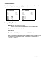
TECHNICAL SUPPORT
Please contact your local dealer first for technical support. Your dealer is knowledgeable about driver
installation, application software and general printer operation. If you still need factory technical
support after contacting your dealer, you may mail any problems through the E-mail account,
“www.amtdatasouth.com”. You can also get the most updated driver or application from the web site
“http://www.amtdatasouth.com”.
© Copyright 2001 by AMT Datasouth Corporation
First Edition: April 2001
User's Guide 2
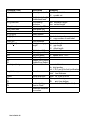
Table of Contents
PRODUCT DESCRIPTION ...................................................................................... 6
Unpacking and Inspection.......................................................................................... 8
INSTALLATION AND CONFIGURATION .......................................................... 9
Finding a Location for the Printer............................................................................ 9
Connecting the Power Cord ................................................................................... 10
Connecting the Printer to Your Host...................................................................... 11
Loading the Ribbon................................................................................................ 12
Loading Media ....................................................................................................... 15
Loading Media when Peel and Present Option is Installed ................................... 18
Loading Media When Cutter is Equipped.............................................................. 19
OPERATING INSTRUCTIONS............................................................................. 20
Switch, Indicators and Connections....................................................................... 20
Label Sensor Calibration Procedure ...................................................................... 21
Printer's Internal Self Test Procedure and Configuration Report .......................... 22
Resetting the Printer to Factory Default Settings .................................................. 25
Entering into HEX Print mode............................................................................... 25
COMMAND QUICK REFERENCE ...................................................................... 26
Command Set for the PPLA................................................................................... 26
Command Set for the PPLB................................................................................... 33
PRINTER DRIVER.................................................................................................. 36
Driver Installation .................................................................................................. 36
How to Use the Driver ........................................................................................... 38
TROUBLESHOOTING AND MAINTENANCE .................................................. 43
Troubleshooting ..................................................................................................... 43
Recovery ................................................................................................................ 45
Preventive Maintenance......................................................................................... 46
Appendix A: Printer Specifications......................................................................... 49
Fonts, Bar Codes and Graphics.............................................................................. 50
Optional Accessories.............................................................................................. 51
Appendix B: INTERFACE SPECIFICATIONS ................................................... 52
Introduction............................................................................................................ 52
Serial ...................................................................................................................... 52
Parallel (Centronics) .............................................................................................. 54
Auto Polling ........................................................................................................... 54
Appendix C: ASCII TABLE .................................................................................... 55
Appendix D: FONTS AND BAR CODES FOR THE PPLA Emulation............. 56
User's Guide 3
Internal Fonts ......................................................................................................... 56
Courier Font Set ..................................................................................................... 61
Internal Bar Codes ................................................................................................. 65
Appendix E: FONTS AND BAR CODES FOR PPLB Emulation ...................... 69
Internal Fonts ......................................................................................................... 69
Symbol Set ............................................................................................................. 70
Internal Bar Codes ................................................................................................. 73
User's Guide 4
Table of Figures
Figure 1 - Fastmark 400 series................................................................................................................. 7
Figure 2 - Included Materials .................................................................................................................. 8
Figure 3 - Switches, Indicators and Connections .................................................................................... 9
Figure 4 - Power Connection................................................................................................................. 10
Figure 5 - Printer to Host....................................................................................................................... 11
Figure 6 - Printhead Latches.................................................................................................................. 12
Figure 7 - Ribbon Core Notch Location ................................................................................................ 13
Figure 8 - Ribbon Loading .................................................................................................................... 14
Figure 9 - Open Printhead Module ........................................................................................................ 15
Figure 10 - Media Spindle and Retainer Disk ....................................................................................... 16
Figure 11 - Loading Media .................................................................................................................... 16
Figure 12 - Loading Media - Peal and Present ...................................................................................... 18
Figure 13 - Loading Media - Cutter....................................................................................................... 19
Figure 14 - Switches and Indicators ...................................................................................................... 20
Figure 15 - Self Test Sample - PPLA Emulation................................................................................... 23
Figure 16 - Self Test Sample - PPLB Emulation................................................................................... 24
Figure 17 - Printhead Location .............................................................................................................. 46
Figure 18 - Platen Roller ....................................................................................................................... 47
Figure 19 - Paper Compartment and Paper Sensor................................................................................ 48
User's Guide 5
(this page intentionally left blank)
User's Guide 6
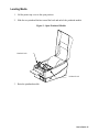
PRODUCT DESCRIPTION
This label printer is a high-performance, low-cost direct thermal/thermal transfer labeling system. Its
user-friendly design and affordable price set a new standard for the Desktop Label Printer in retail,
office, industrial, and many other applications.
The printer is designed with the most efficient memory management technology - True Speed and
prints at a speed of 2 to 3 inches per second. When bundled with its smart printer driver, the user can
easily print out bar codes, texts and graphics from any editing application (e.g. CodeSoft, BarTender)
under Windows 95/98/2000 and NT. All popular bar codes and fonts are resident in the printer
memory to handle versatile applications.
The solidly designed mechanism allows quick and easy media (paper) and ribbon loading. The
optional Peel and Present and Cutter provide the alternatives of fan-fold label and continuous paper
handling.
This printer is a compact, highly integrated, high performance and high resolution on-site labeling
system.
The User’s Guide will help you understand basic operations of the printer such as set-up, installation,
configuration and maintenance. Before reading the manual you should first identify your printer
model. To determine the model and serial number of your printer, look at the label located on the
bottom of the printer.
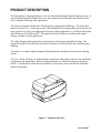
Figure 1 - Fastmark 400 series
User's Guide 7
UNPACKING and INSPECTION
This printer is packed in a heavyweight carton and custom recyclable foam for environmental
protection. Inspect the shipping carton and contact the carrier directly to report any suspected damage.
Consider the following when unpacking:
♦
♦
♦
♦
♦
The container should stay right side up.
Lift the printer out of the box carefully.
Remove the accessory items.
Set the printer on a solid, flat surface.
Inspect the shipping container and printer for any damage that may have occurred during
shipping.
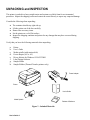
Verify that you have the following materials when unpacking:
a.
b.
c.
d.
e.
f.
g.
h.
Printer
User’s Guide
Media spindle (with retainer disk)
Power adapter (AC to AC)
Driver diskette for Windows 95/98/NT/2000
Label Design Software.
Sample Media
Sample Ribbon (Thermal Transfer printers only)
Power Adapter
Printer
User's Guide
Media Spindle
Diskette & Software
Figure 2 - Included Materials
User's Guide 8
INSTALLATION AND CONFIGURATION
Serial Port
Power LED
Power Jack
Ready LED
Feed button
Parallel Port
On Switch
Figure 3 - Switches, Indicators and Connections
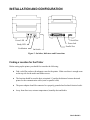
Finding a Location for the Printer
Before setting up the printer you should first consider the following:
♦
Find a solid flat surface with adequate room for the printer. Make sure there is enough room
on the top side for the media and ribbon access.
♦
The location should be near the host or terminal. Consider the distance between host and
printer for the communication cable (serial or parallel cable)
♦
The power adapter should be connected to a properly grounded and isolated electrical outlet.
♦
Away from direct sun, extreme temperatures, humidity dust and debris.
User's Guide 9
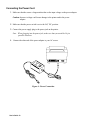
Connecting the Power Cord
1. Make sure that the source voltage matches that on the input voltage on the power adapter.
Caution: Incorrect voltage could cause damage to the printer and/or the power
adapter.
2. Make sure that the power switch is set to the Off, ”O”, position.
3. Connect the power supply plug to the power jack on the printer.
Note: When plugging into the power jack, make sure that you avoid the 36 pin
parallel connector.
4. Connect the other end of the power adapter to your AC source.
Figure 4 - Power Connection
User's Guide 10
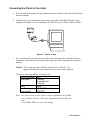
Connecting the Printer to Your Host
1.
You can connect the printer with any standard Centronics Parallel cable to the parallel port of
the host computer.
2.
Alternatively you can connect the printer with a serial cable to the RS-232C port of your
computer or terminal. (For PC compatibles, the RS-232C port is COM1, COM2 or COM3.)
Figure 5 - Printer to Host
3.
If you use the serial port with your own cable, refer to the Appendix A and check the pin
connection. Be sure that the speed (baud rate) and protocol are consistent between printer
and host.
Caution: Pin 9 on the serial port is directly connected to +5volts DC. It is
suggested that this pin is not connected in your cable, unless required.
The factory default parameters of serial port are:
Speed (baud rate) 9600
Data format
1 start bit,
8 data bits and
1 stop bit.
Parity
None
Handshaking
XON/XOFF as well as
(Flow control)
RTS/CTS
Note: It is not necessary to set a switch or send a command for the parallel
and serial port selection. The printer automatically detects the active
port.
Print a SELF-TEST to review serial settings.
User's Guide 11
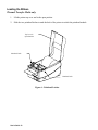
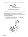
Loading the Ribbon
Thermal Transfer Media only
1.
Lift the printer top cover and to the open position.
2.
Slide the two printhead latches toward the back of the printer to unlock the printhead module.
Top Cover in
Open Position
Printhead Latch
Printhead Latch
Figure 6 - Printhead Latches
User's Guide 12
3.
Raise the printhead module to the vertical position.
4.
Verify that the Supply Core and the Take-up Core have two slots on the left side of the ribbon
core when the ribbon is positioned to go into the printer. These notches will be inserted into
the notches on the Left Ribbon Holders.
Note: The notches are the drive mechanism for the ribbon. If the slots in the core are not
present or if they are in the wrong position, contact your ribbon supplier to obtain a
correct ribbon.
Notch
Figure 7 - Ribbon Core Notch Location
User's Guide 13
5.
Unwrap the ribbon roll and place the supply roll into the supply holder of the printhead
module.
Insert the left end of the ribbon supply onto the supply holder spindle first, and then insert the
right end. Make sure that the Ribbon Core Slots match the notches on the Ribbon Drive
Mechanism.
6.
Place the Take-up core into the take-up holder of the printhead module.
First insert the left end of the Take-up core into holder spindle, and then insert the other end.
Make sure that the Ribbon Core Slots match the notches on the Ribbon Drive Mechanism.
Take-up Holder
Ribbon
Supply Roll
Supply Holder
Figure 8 - Ribbon Loading
7.
Manually rotate the Take-up core until the transfer (typically Black) portion of the ribbon,
from the Supply Holder starts onto the Take-up core.
8.
Close and latch the Printhead module.
Note: The printer must be set to the Thermal Transfer mode to ensure the end of ribbon is
detected. This setting may be made using the Windows drivers, Utility Software, or sending
the appropriate printer commands via the host.
User's Guide 14
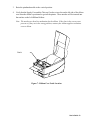
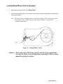
Loading Media
1.
Lift the printer top cover to the open position.
2.
Slide the two printhead latches toward the back and unlock the printhead module.
Figure 9 - Open Printhead Module
Printhead Latch
Printhead Latch
3.
Raise the printhead module.
User's Guide 15
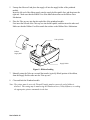
4.
Insert the media spindle into core of the label media (the Retainer Disk should be on the
right).
Retainer Disk
Media Spindle
Figure 10 - Media Spindle and Retainer Disk
5.
Insert the spindle and media into the slots in the printer. The media should feed from the top
of the roll.
6.
Slide the media to the far left and slide in the guide until it is snug with the media.
7.
Move the Right Media guide to the far right of the printer. The Right and Left Media Guides
are located under the printhead module.
Note: The Right and Left Media Guides are 'U' shaped parts and are located at the bottom of
the paper path. Only the right media guide can be moved. The media should be
snugly positioned in the 'U' portion of the guides.
Media guides
Figure 11 - Loading Media
User's Guide 16
8.
Pull out 6 inches of media and thread the end of the media between the Right and Left Media
Guides.
9.
Slide in the Right Media Guide until it is snug with the media.
Note:
If the guides are positioned incorrectly, the media sensor may not sense
the form properly.
If too loose the media may slide out from under them, uncover the
paper out sensor and indicate a false paper out message.
If too tight so that the media may buckle and a paper jam could
occur.
10. Thread the media over the roller until approximately 2 inches of the media shows out of the
printer. (MAKE SURE THAT THE LABELS ARE FACING UP.)
11. Press the printhead module down firmly until it snaps into place.
12. Close the top cover.
13. Turn on the printer.
14. If you are using die-cut media, press the ”FEED” button to advance the first label into the
standby position.
Note: If the labels do not feed correctly, run the Label Sensor Calibration test (see the
section on Label Sensor Calibration).
Note: The first time media is loaded, the label sensor must be calibrated. After this initial
calibration, further calibration is not needed unless the media length, media changes
or irregular feeding occurs. See Label Sensor Calibration for instructions on how to
calibrate the Label sensor.
User's Guide 17
Loading Media when Peel and Present Option is Installed
1.
Follow the same procedures in "Loading Media" up to closing of the Printhead Module.
2.
Peel off 6 inches of labels from its backing.
3.
Thread the label backing over the platen roller, over the Peel and Present Bar then back under
the Peel and Present Bar towards the platen.
4.
Turn on the power to “1” position.
5.
With the Printhead module still open, press “FEED” button. The printer will advance the
backing. Once the label backing comes out of the front of the printer, turn off the power to
“O” position.
6.
Pull down the printhead module down and latch it closed.
7.
Close the top cover.
8.
Turn on the power to “1” position.
9.
Press the Feed key to feed up to the first label in the printer.
Note: The printer must be configured for Peel and Present Mode. This setting may be made in
the windows driver, utility software, label design software or using printer commands
from the host.
Label
Backing
Figure 12 - Loading Media - Peal and Present
User's Guide 18
Loading Media When Cutter is Equipped
1.
Follow the same procedure as “Loading Media”.
2.
After you thread the media over the platen roller, thread the media through the horizontal gap
at the cutter module.
Note: The printer must be configured for Peel and Present Mode. This setting may be made
in the windows driver, utility software, label design software or using printer
commands from the host.
Cutter
Figure 13 - Loading Media - Cutter
Caution: When removing a label from a printer with the Cutter option make
sure that the cutter is not rotating before removing the label or when
manually opening the printer.
User's Guide 19
OPERATING INSTRUCTIONS
Serial Port
Power LED
Power Jack
Ready LED
Feed button
Parallel Port
On Switch
Figure 14 - Switches and Indicators
Switch, Indicators and Connections
Device name
On/Off switch
(power switch)
FEED button
Function
Usage
Controls printer
On – normal operation
power
Off – loading paper and ribbon
Advances the media Press once to advance a label.
stock to first printing Press and Hold while powering on to run Label
position of next label
Sensor Calibration test.
Continue to press and hold to print out the selftest pattern and enter into Hex mode.
Press to continue, when READY LED is
blinking.
Green – printer is ready to operate
READY indicator Shows the printer
status
Blinking – printer is paused; press “FEED”
button to continue operation
Off – printer power off
POWER indicator Shows the power
and error status
Green – printer power on
Blinking – error has occurred
Power jack
Connected to power Connected with power supply transformer plug
adapter
RS-232 serial port Communication
Connected to host (RS-232 COM port), terminal
or KDU
Parallel port
Communication
Connected to host (Centronics )
Top cover
Protects the printer
Lift and reach the media/ribbon compartment
media and ribbon
User's Guide 20
Label Sensor Calibration Procedure
The Label Sensor Calibration procedure allows the printer to calibrate the Label Sensor to the media
type and length being used. The Label Sensor in this procedure looks at the back of the media sensing
for:
Black Bar Media
Gap Media
Or, Continuous Feed Media
1.
Power the printer on while pressing the Feed button on the front panel.
2.
When the feed motor begins moving, release the “FEED” button.
3.
The printer will feed approximately 12 inches of blank media.
4.
Once the printer has stopped feeding the user can, open the printhead module and manually
reverse feed the media back to the first label.
5.
Press the Feed button again to align the media to the top of the next label.
Notes:
These steps are very important and must always be carried out after the first installation and
each time the media type (color, size, backing, etc) is changed. Failure to run the Label
Sensor Calibration test may result in the label registration errors and label-empty detection
being incorrect.
User's Guide 21
Printer's Internal Self Test Procedure and Configuration Report
1.
Make sure that media is installed.
2.
Press and hold down the Feed Button while powering on the printer.
3.
The printer will begin the Label Sensor Calibration test.
4.
Continue to hold the Feed button until the Self Test begins.
5.
After feeding 12 inches of blank media, the printer will begin printing out the current
configuration and font list.
6.
The printer will print the following information on the installed media:
Firmware version,
ROM checksum,
RS-232 settings,
Thermal transfer/Direct thermal settings,
Hardware configuration and,
Font types.
7.
If the installed emulation is PPLB emulation, the printer will enter character Hex Print Mode.
8.
To exit the Hex mode, press the Feed button again.
The following pages are examples of the printer's Self Test mode. The samples that you print may be
different. Before requesting service, if possible, please have this page ready.
User's Guide 22
Self Test Pattern for PPLA
Emulation
designation
Figure 15 - Self Test Sample - PPLA Emulation
User's Guide 23
Self Test Pattern for PPLB
Emulation
designation
Figure 16 - Self Test Sample - PPLB Emulation
User's Guide 24
Resetting the Printer to Factory Default Settings
Resetting the printer back to Factory settings will set the printers non-volatile memory back to a
known condition. To reset the printer to its factory defaults:
1. Printer must be powered On.
2. Press and hold the “FEED” button for about 10 seconds.
3. The “READY” LED will turn off.
4. Release the “FEED” button.
5. The Power LED will then turn off for about 2 seconds after that.
6. When both LED’s turn on again, the printer is reset to the factory default condition.
Note: All settings are stored in non-volatile memory and will not be erased even by turning the
printer off. After a reset, send to the printer the appropriate commands to re-configure the
printer's software to the appropriate installed options, and run the Label Sensor
Calibration test.
Entering into HEX Print mode
Hex Print mode is a valuable tool for solving programming print issues. It can be used to
determine if the printer is receiving the correct information and if the printer is receiving any
extra control codes.
Note: Hex mode is only available when PPLB emulation is installed.
1.
Make sure that media is installed.
2.
Power the printer on while pressing the button on the front panel.
3.
The printer will begin the Label Sensor Calibration test.
4.
Continue to hold the Feed key until the Self Test begins
5.
After feeding 12 inches of blank media, the printer will begin printing out the current
configuration and font list.
6.
The printer will then enter into Hex Print mode.
7.
To exit the Hex mode, press the Feed button again.
User's Guide 25
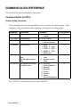
COMMAND QUICK REFERENCE
This section lists all software commands of the printer.
Command Set for the PPLA
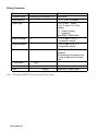
System Setting Commands
These commands will cause related parameters to be saved in the non-volatile memory. These
parameters will be stored unless other commands or a front panel reset changes them.
Command
<STX>KI4n
Description
Media empty check
<STX>KI5nn Set gap length
<STX>KI7n Set transfer type
<STX>KI8n
Set baud rate
<STX>KI;n
Set standard control
code.
Set alternative control
code.
Set symbol set for ASD
smooth font set
<STX>KI<m
Parameter
Factory default
n : 0 - disable,
1
1 - enable.
nn: 01 to 10 (mm)
1
n : 0 - direct thermal,
1
1 - thermal transfer.
n : 0 - 9600,
0
1 - 2400, 2 - 2400,
3 - 19200, 4 - 4800,
5 - 38400, 6 - 2400,
7 - 9600 baud.
n: 1 - Standard control
1
code
2 - alternate control
code
m : 0 - USASCII,
0
1 - United Kingdom,
2 - Spanish,
3 - Swedish,
4 - French,
5 - German,
6 - Italian,
7 - Danish/Norwegian.
Note: <STX>KI7n command is ignored by model FM402DT
User's Guide 26
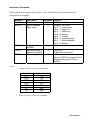
Interaction Commands
These commands only apply to the serial port. They allow the host to request the status and
configuration of the printer.
Command
<SOH>#
<SOH>A
Description
Reset
Send a readable
status string
<SOH>B
Toggle pause
condition
Send the number of
labels to be printed
Send status byte
<SOH>E
<SOH>F
Response Contents
Y
<XOFF><XON>T
Y
<8 bytes, Y/N> <CR>
byte 1 : Y - printer busy
byte 2 : Y - paper out
byte 3 : Y - ribbon out
byte 4 : N (always)
byte 5 : Y - printing
byte 6 : Y - printer paused
byte 7 : Y - label presented
byte 8 : N (always)
N
Y
Y
0000<CR>
no label left to be printed
n<CR>
Same as <SOH>A, except bit 1 to 8
corresponding to byte 1 to 8 of
<SOH>A.
Notes:
1.
Control codes for the printer commands.
Symbol
XON
XOFF
STX
SOH
ESC
LF
CR
Code (hexadecimal)
11H
13H
02H
01H
1BH
0AH
0DH
2. There is no space code in the command.
User's Guide 27
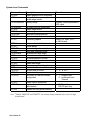
System Level Commands
Command
<STX>a
<STX>cxxxx
<STX>Dxxxxxxx
Description
Enable page/job echo characters
Set continuous paper length and
disable edge sensor
Memory dump**
<STX>Exxxx
<STX>e
<STX>F
<STX>fxxx
<STX>G
<STX>I
Set copy count for stored label
Enable edge sensor
Feed a page
Back feed from top position
Print stored label
Download graphics
<STX>J
<STX>j
<STX>KQ
<STX>L
<STX>Mxxxx
<STX>m
<STX>n
<STX>Oxxxx
<STX>P
<STX>Q
<STX>r
<STX>Sn
<STX>T
<STX>Vn
Set pause for each label
Cancel pause
System configuration details
Enter label formatting state
Set maximum label length
Set measurement in metric
Set measurement in inches
Set start of print position
Enable data dump
Clear memory (fonts & graphics)
Select reflective sensor
Set feed rate for motor
Print test pattern
Set Cutter or Peel and Present
configuration
<STX>v
<STX>Wn
Printer version information
Graphics/fonts/labels and memory
status details
Release file from printer memory
<STX>x
Remarks
xxxxxxx : memory address in
HEX value
either PCX, BMP, PCX
or HEX format
n : ‘A’, ‘B’ or ‘C’
n : ‘1’ - enable cutter,
‘4’ - enable peel and
Present
n : ‘G’, ‘F’ or ‘L’.
RS-232 port only
Note: **Models FM402DT and FM402TT, the memory dump command only needs a 6-digit
hexadecimal.
User's Guide 28
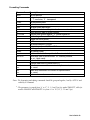
Formatting Commands
Command
:xxxx
An
Cxxxx
cxx
Dwh
E
G
<STX>Sn
Hxx
M
m
n
Pn
Qxxxx
Rxxxx
r<n..n>
sm<n..n>
Txx
z
+xx
>xx
-xx
<xx
^xx
Description
Set cut amount
Set print mode
n : ‘1’- exclusive, ‘2’ - transparent
Set horizontal offset
Set cut amount
Set pixel width and height
Form feed and return to system level command mode
Store previous data to global register
Retrieve from global register. n : global register ID
Set heating value, xx=01 to 20
Toggle the mirror mode
Set measurement in metric
Set measurement in inches
Set print speed. n=’A’, ‘B’, or ‘C’ **
Set copy count
Set vertical offset
Retrieve label data from printer buffer. <n..n> : label name
Save label data to printer buffer. m : memory module,
<n..n> : label name
Set end-of-line code, xx : hex value
Change slash zero to normal zero (0).
Make auto increment for numeric or alphanumeric,
xx : count
Make auto decrement for numeric or alphanumeric,
xx : count
Set count amount, xx : count
Notes: The formatting and editing commands should be grouped together, lead by <STX>L and
ended by E command.
**
: The parameter is ranged from ‘A’ to ‘C’ (1, 1.5 and 2 ips) for model FM403TT, while for
models FM402DT and FM402TT it is from ‘A’ to ‘D’ (1.5, 2, 2.5 and 3 ips).
User's Guide 29
Editing Commands
Command
General format
Print direction
format
rthveeeyyyyxxxx<string><CR>
r
Description
See below
‘1’, ’2’, ’3’ or ‘4’ (rotation)
Object type
t
Width multiplier
h
‘0’ to ‘9’ and ‘:’ (fonts) **,
‘A’ to ‘Z’ and ‘a’ to ‘z’ (bar
codes),
‘X’ (lines or boxes),
‘Y’ (graphics).
See Object Table below
‘1’ to '9' and ‘A’ to ’ O’.
‘0’ stands for default.
Height multiplier
v
‘1’ to ‘9’ and ‘A’ to ’ O’,
‘0’ stands for default.
Bar code height
eee
This is ignored for box, line and
graphics.
It represents point size for font
‘9’ and symbol set for Courier
font.
Y coordinate
X coordinate
Data
yyyy
xxxx
<string>
Note: **The model FM403TT does not include Courier fonts.
User's Guide 30
Depends on object types
Object Table
The following table is used for the Object Type, 't', in the Editing Command Table.
Object
L : line
String
Lwwwhhh
Description
www : width,
hhh : height.
L : line
Lwwwwhhhh
wwww : width,
hhhh : height.
B : box
Baaabbbcccddd
aaa : horizontal width
bbb : vertical height
ccc : thickness of top and bottom edges
ddd : thickness of left and right bars
B : box
Baaaavvvvccccdddd aaaa : horizontal width
vvvv : vertical height
cccc : thickness of top and bottom edges
dddd : thickness of left and right bars
bar code
bar code data
Bar codes (and human readable text) will be
(Range ‘A’ to ‘Z’ or
printed according to the selected bar code
‘a’ to ‘z’)
type (‘A’ to ‘Z’ or ‘a’ to ‘z’).
Text
text data
Text data will be printed according to the
(Range ‘0’ to ‘9’)
selected font (‘0’ to ‘9’).
Yfile name
‘Y’ and the file that was downloaded by
<STX>I command.
User's Guide 31
Font Downloading Commands
Such commands are only used for soft fonts with PCL format.
Command
ESC *c###D
ESC )s###W
ESC *c###E
ESC (s###W
Description
assign the soft fonts ID number (### : 100 ~ 999)
download font descriptor (### : length of font descriptor)
set character code (### : 1 ~ 255)
download character descriptor and image
(### : length of character descriptor and image)
Note: No spaces are after the escape character.
User's Guide 32
Command Set for the PPLB
All PPLB commands must end with <LF> or <CR>+<LF> codes. No spaces are allowed between
parameters and leading command character.
Command
Ax,y,rot,font,hm,vm,nr,string
Description
Print text.
Parameter
font: 1to 5 for internal font and A to Z
for soft font.
Bx,y,rot,bar,nw,ww,v,hum,string Print Bar Code.
nw: width of narrow bar
bar: barcode
ww: width of wide bar
selection
v:
bar code height
hum: B for printing readable code
and N for disabling.
bx,y,type,[…]
Print 2D Bar Code type: M for Maxi code and P for PDF
417
Ccn,dn,just,step,string
Counter declaration cn: counter index
dn: digit number
just: L,R,C and N for field justification
step: step value
Dp1
Heat setting
p1: density, 0 to 15
EI
Print soft font
names
EKstring
Delete soft font
string: soft font name or “*” to delete
all soft fonts
ESstring,….
Download soft font
FE
End form store
FI
Print form names
FKstring
Delete form
string: form name or “*” to delete all
forms
FSstring
Execute form
string: form name
FSstring
Save form
string: form name
GGx,y,string
Print graphics
string: graphic name
GI
Print graphic list
GKstring
Delete graphics
string: graphic name or “*” to delete
all graphics
GMstring,size<LF>…
Store graphics
string: graphic name
size: graphic size in bytes
User's Guide 33
Command (Cont)
Ip1,p2,001
Description
Select symbol set**
JB
JF
LEx,y,hlen,vlen
Disable back feed**
Enable back feed**
Line draw by
hlen: horizontal length
exclusive
vlen: vertical length
Line draw by OR
Draw white line
Clear frame buffer
Select options**
Print label
p1: label set number
p2: copy number of each label
Print automatic
Set label and gap
p1: label length
length**
p2: gap length
p3: offset length
Set label width**
w: label width
Set origin point**
Set print speed
p1: speed value, 1 to 3
Print configuration
Disable Error Report
Enable Error Report
Define variable
vn: variable index
dn: digit number
just: L,R,C and N for field justification
Draw box
ex, ey: end position
thick: line thickness
Setup serial port**
baud: 38,19,96,48 or 24
Set print direction
ZS:
print from top
ZB:
print from bottom
Enable/disable
power-on default is ZN(disabled)
store-to-Flash++
Download variables
or counters
LOx,y,hlen,vlen
LWx,y,hlen,vlen
N
O[,C][,N][,D]
Pp1[,p2]
PAp1[,p2]
Qp1,p2[,+p3]
qw
Rx,y
Sp1
U
UN
US
Vvn,dn,just,string
Xx,y,thick,ex,ey
Ybaud
ZT
ZB
ZS
ZN
?
User's Guide 34
Parameter
p1: 7 or 8 data bits
p2: symbol set
Command (Cont)
d0,euro
d1,hadj
d2,hadj
Notes:
1.
2.
3.
4.
5.
6.
7.
Description
Parameter
Enable/disable
0: disable European dollar mark.
European dollar
1: enable
mark**
Set horizontal
hadj: adjustment in dots.
position adjustment**
Same as d1 except the parameter is not saved to nonvolatile memory.
x and y represents horizontal and vertical co-ordinate values.
hm and vm stand for horizontal and vertical multipliers.
rot is the rotation direction, its value is from 0 to 3.
nr is either N for normal printing or R for reverse printing.
string is bracket by double quote marks, e.g. “text”.
** Commands will cause the printer to save the parameters to non-volatile memory.
ZS takes effect only if flash memory board is installed.
User's Guide 35
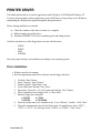
PRINTER DRIVER
The bundled printer driver is used for applications under Windows 95/98/2000 and Windows NT.
You may run any popular software application, such as MS-Word, as long as they are for Windows
and printing the contents to the printer through the designated driver.
Before starting installation you should:
♦
♦
♦
Check the contents of the driver to ensure it is complete.
Make a backup copy of the driver.
Read the README.TXT file for installation guide and change notices.
Under the root directory of the floppy there are some sub-directories
-
WIN98
WIN95
NT40
WIN2000
Select the proper directory for installation according to your operating system.
Driver Installation
♦
♦
Windows needs to be running.
Insert the appropriate printer driver diskette into the floppy disk drive.
1.
2.
3.
4.
5.
6.
7.
8.
9.
Click the “Start” button.
Select “Settings”, then “Printers”
Double click the “Add Printer” icon.
At the Add Printer Wizard, Click “Next”.
Specify the “Network” or “Local” button and click the “Next” button.
Select “Installation from Floppy Disk” or "Have Disk".
Enter the floppy drive and path.
A:\WIN95
A:\NT40
A:\WIN98
A:\WIN2000
Select the printer name to be installed on the “List of Printers”, window. Click “Next”.
Select the communication port for the label printer. For parallel port, select “LPT1:”,
“LPT2:” or “LPT3”, for serial port select “COM1:” or “COM2:”., Click "Next".
User's Guide 36
10. You may wish to change the Printer Name to be more descriptive. Also select this
printer as the Default printer. Click "Next".
11. Select whether you want a test page to be printed, then click on Finish.
12. After the related files have been copied to your system, the procedure is complete.
Notes:
1.
If you are just updating your driver, make sure to delete the previous version first.
2.
If you install new bar code application software like BarTender, LabelView or CodeSoft, the
driver should be activated and set as the current printer driver.
User's Guide 37
How to Use the Driver
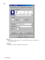
After the driver is installed, you can open the Printer's dialogue box and make parameter settings:
Windows 95/98/2000/NT4.0 - Start ➩ Settings ➩ Printers ➩ Printer Name ➩ Properties
Parameter setting:
After entering the Selected Printer you can change the parameters to meet your configuration and
needs. The following Format is from Windows 98.
User's Guide 38
Details Tab
Print to the following port
This allows you to select the IO port to link with the printer. The port may be one of
parallel (LPT), serial (COM), network port or file.
If the communication port is the serial port (COM1: or COM2:), check the baud rate and
flow control as they must be consistent between host and printer. The printer’s baud rate
is printed on the following the self-test page. The factory default baud rate is 9600.
Print using the following driver
This must match the printer that is attached (for the FM402DT, FM402TT or FM403TT)
when using the label printer.
User's Guide 39
Paper
Paper size
Select the label size for your printer. The selected label size may be a little longer than
that of the physical label.
Orientation
Set portrait or landscape according to the print direction.
User's Guide 40
Paper source
Select one of the following items:
T/T & Media with Gap
T/T & Media with Black Line
T/T & Continuous Media
D/T & Media with Gap
D/T & Media with Black Line
D/T & Continuous Media
T/T stands for thermal transfer (ribbon) mode and D/T for direct thermal model (without
ribbon).
Media choice
Set the heat value or darkness from this field. The darkness value ranges from 0 to 15.
Copies
This function designates the number of printed copies of each page.
More Options
To use the cutter and peeler function you need to select More Options and select one of
the items.
w/o Cutter and Peeler
Cutter Enabled
Peeler Enabled
User's Guide 41
Device Options
Print speed for the FM402TT can be set at 1 to 3 IPS.
Print speed for the FM402DT and FM403TT can be set for 1 to 2 IPS.
User's Guide 42
TROUBLESHOOTING AND MAINTENANCE
Troubleshooting
Generally, when a malfunction or an abnormal condition occurs, the “POWER” LED will keep
blinking. Printing and communication between the host and printer will stop.
Power and Ready LEDs blink together at the same time
Possible Problems Solutions
Missing gap
Check the media path
Check the paper sensor
Media out
Media not installed
Media jam
Install a Media roll
Install a media roll
Clear the jam
Printhead module is
not closed
Close and latch the
printhead module
Remarks
If using continuous media with
Windows then in the Paper Tab
section continuous should be
selected.
Verify that the media is routed
correctly.
Power and Ready LEDs alternate blinking **
Possible Problems Solutions
Ribbon has run out Supply the ribbon roll
Remarks
Does not apply to direct thermal. If
you use direct thermal and run under
Windows the Ribbon should not be
selected.
Ribbon jam
Clear the jam
not for direct thermal
Ribbon sensor error Replace the ribbon sensor not for direct thermal
Note: **The FM402DT does not use a ribbon and should not display this error.
Only the Power LED blinks
Possible Problems Solutions
Serial I/O error
Check the baud rate
Check the flow control
Memory full
Add the extension RAM
Cutter failed, or jam Check the cutter
at cutter
Clear the jam
Hardware error
Call for service
Remarks
Only when cutter is installed.
User's Guide 43
Host and Data related errors
Possible Problems
Solutions
Host Displays:
Verify that the communication cable is connected securely to
"Printer Time Out"
the parallel or serial port on the PC and to the connector on
the printer.
Data has been sent,
but there is no output
from the printer.
Verify that the Power LED is illuminated. If not, verify that the
power cord is connected, the power switch is at position ‘1’.
If Power LED is still not illuminated, check the fuse in the
power adapter.
Print a Self Test and verify that the emulation being used is the
correct one.
If using Windows, verify the active printer driver.
Blank or Extra lines in the label
Problem
Solutions
Dark Vertical lines that Verify Program does not have an inadvertent line command.
go the full length of the
Clean printhead. Look for dirt or dust in the print area.
label.
Faulty Printhead. Replace the printhead.
Blank vertical lines that Verify Program does not have an inadvertent line command.
go the full length of the Direct Thermal printing:
label.
Verify label stock does not have voids in the Direct Thermal
coating.
Thermal Transfer printing.
Verify ribbon is not damaged in the area in question.
Verify that ribbon is not folded or wrinkled.
Faulty Printhead. Replace the printhead.
Ribbon not rotating
Verify that the ribbon cores (Supply and Take-up) have
properly
notches on the proper side (Left)
Verify that the notches in the ribbon core are in the correct
locations.
Verify ribbon is tight between the two ribbon cores.
Verify that the ribbon is not folding.
Dust on or dirty on
Clean Platen Roller.
platen
User's Guide 44
Print Quality
Problem
Too light in Thermal
Transfer
Too light in Direct
Thermal
Too dark in Direct
Thermal mode
Solutions
Verify printer is set for Thermal Transfer stock.
Verify that a certified ribbon is installed.
Verify that the Media is certified to work with the ribbon.
Note: Direct Thermal media can be used with a ribbon,
however inadequate heat transfer may result in light
print. It is not recommended to use Direct Thermal
media with a Thermal Transfer ribbons.
Clean the printhead.
Adjust the Darkness setting.
Slow down the print speed
Verify printer is set for Direct Thermal stock.
Verify that the stock is coated with Direct Thermal material.
Verify that a ribbon is not installed.
Clean the printhead.
Adjust the Darkness setting.
Slow down the print speed
Clean the printhead.
Adjust the Darkness setting.
Adjust the print speed
Recovery
To continue your print jobs after any abnormal conditions have been recovered, simply press the
Feed button or restart the printer. Make sure that the LED's are not blinking and you may need to
re-send the print job.
User's Guide 45
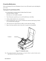
Preventive Maintenance
Before performing any Preventive Maintenance be sure to turn off the printer's power and unplug the
power cable.
Cleaning the Thermal Printhead (TPH)
It is recommended at a minimum that the Printhead should be cleaned:
Each time a Ribbon is changed.
Each time a new roll of media is installed.
1.
Turn off the printer, open the top cover, and if installed remove the ribbon.
2.
Lift the printhead module to the vertical position.
3.
Rub the printhead with a piece of cotton, which has been moistened with Isopropyl Alcohol,
or use a thermal head cleaning pen.
4.
Check for any traces of discoloration or adhesive on the cotton after cleaning.
5.
Repeat if necessary until the cotton is clean, after it is passed over the printhead.
Printhead
Figure 17 - Printhead Location
Note: The printhead should be cleaned at least every time the ribbon is replaced and more often
depending on actual usage and conditions.
User's Guide 46
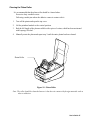
Cleaning the Platen Roller
It is recommended that the platen roller should be cleaned when:
Excessive dusty condition exists.
Following a media jam where the adhesive comes in contact with it.
1.
Turn off the printer and open the top cover.
2.
Lift the printhead module to the vertical position.
3.
Rub the full length of the platen available with a piece of cotton, which has been moistened
with Isopropyl Alcohol.
4.
Manually rotate the platen and repeat step 3 until the entire platen has been cleaned.
Platen Roller
Figure 18 - Platen Roller
Note: The roller should be cleaned whenever it has been in contact with foreign materials such as
dust or adhesives.
User's Guide 47
Cleaning the Paper Compartment
It is recommended that the Paper Compartment be cleaned regularly if exposed to a dust
environment. This will keep dirt and dust from contaminating or damaging your printer
(Printhead and Platen).
1.
Turn off the printer and open the top cover.
2.
Remove paper dust by blowing using compressed air or vacuuming.
3.
Clean the paper compartment with cotton, which has been moistened with mild
detergent.
Cleaning the paper sensor
It is recommended that the Paper Sensor be cleaned regularly if exposed to a dusty
environment. This will prevent false paper OUT or paper IN conditions.
1.
Turn off the printer and open the top cover.
2.
Remove paper dust by blowing using compressed air or vacuuming.
3.
Clean the two Paper Sensor LED's with cotton stick, which has been moistened with
Isopropyl Alcohol.
Paper Compartment
Paper Sensor
Figure 19 - Paper Compartment and Paper Sensor
User's Guide 48
Appendix A: Printer Specifications
Specification
Print method
Resolution
Maximum print
width
Maximum print
length
Maximum print
speed
Onboard RAM
Media type
Maximum label
roll diameter
Label indexing
Ribbon types
Ribbon size
Interface
Dimension
Weight
Electrical
FM402DT
FM402TT
FM403TT
Direct thermal
Direct thermal and thermal transfer
203 DPI
300 DPI
(8 dots/mm)
(12 dots/mm)
4.2 in. (107 mm)
4.10 in. (104 mm)
43 in. (1090 mm)**
29 in. (736 mm)**
2 inches (50.8 mm) 3 inches (76.2 mm) 2 inches (50.8 mm)
per second
per second
per second
512 K bytes
2 M bytes
I. Direct thermal:
Paper, vinyl, visible light and infrared scannable label, tag
stock, butt cut or die cut, with various adhesives.
II. All above media, plus thermal transfer
paper or vinyl labels and tags, butt cut
or die cut, with various adhesives.
4 in.(102mm) outside diameter, 1 in.(25.4mm) inside
diameter
Black stripe and gap
Wax, Wax/resin and Resin
OD 1.45 in. (37 mm); ID 0.5 in. (12.7mm)
RS-232 serial and Centronics parallel ports, auto polling for
both ports
W7.3 in. x D10.9 in. x H6.0 in.
(W186 mm x D278 mm x H153mm)
1.7 kg (3.74 lbs.)
1.9 kg (4.1 lbs.)
FCC class B
FCC class A
CE, UL and CUL approved. Input 19 VAC or 24 VDC
(min. 2.5 A), 50/60 Hz
Operating
temperature
Storage
temperature
Humidity
Windows driver
Rotation
40° to 140°F (5° to 38°C)
-40° to 140°F (-40° to 60°C)
15 to 85% RH
Win, 95, 98, 2000 and NT
0o, 90 o, 180 o and 270 o , 4 direction rotations
User's Guide 49
Fonts, Bar Codes and Graphics
The specifications of fonts, bar codes and graphics depend on the printer emulation. The emulation is
a printer programming language, through which the host can communicate with your printer. There
are two printer-programming languages: PPLA and PPLB. Only one emulation can be resident at a
time.
Printer Programming Language A, PPLA
Specification
General fonts
ASD smooth fonts
FM402DT
FM402TT
FM403TT
7 alpha-numeric fonts, OCR A and OCR B
6, 8, 10, 12, 14 and 18 points
4, 6, 8, 10, 12, 14,
and 18 points
Symbol sets for
USASCII, UK, German, French, Italian, Spanish, Swedish, and
smooth fonts
Danish/Norwegian
Courier fonts
8 symbol set (PC, PC-A, PC-B, EAMA94, Roman8, Legal, Greek and Russian)
Soft fonts
Downloadable PCL fonts
Font expandability
1x1 to 24x24
Bar code types
Code 39, Code 93, Code 128/subset A, B, C, Codabar,
Interleave 2 of 5, UPC A/E/2 and 5 add-on, EAN-8/13,
UCC/EAN-128, Postnet, Plessey, HBIC, Telepen and FIM.
MaxiCode and PDF417 (2D symbologies).
Graphics
PCX, BMP, IMG and HEX formats
Printer Programming Language B, PPLB
Specification
General fonts
Symbol sets
(Code pages)
FM402TT
FM403TT
5 fonts with different point sizes
8 bits: Code page 437, 850, 852, 860, 863 and 865.
7 bits: USA, British, German, French, Danish, Italian,
Spanish, Swedish and Swiss.
Soft fonts
Downloadable soft fonts
Font expandability
1x1 to 24x24
Bar code types
Code 39(checksum), Code 93, Code 128/subset A, B, C,
Codabar, Interleave 2 of 5(checksum), Matrix 25, UPC A/E 2
and 5 add-on, EAN-8/13, Code 128UCC, UCC/EAN, Postnet,
German Postcode.
MaxiCode and PDF417 (2D symbologies).
Graphics
User's Guide 50
FM402DT
PCX and binary raster
Optional Accessories
♦
♦
♦
♦
♦
♦
♦
Serial (RS-232) cable
External media suppler (for media roll with max. 8 inch OD)
Peel and Present
Cutter
Flash memory
Font board
Extension RAM ++ (0.5M for models FM402DT, FM402TT and FM403TT and 1M for the
FM403TT model)
Notes:
**
: Since this printer uses band buffers technology the maximum print length depends on the
printout contents. Text and bar code printing typically allow long label lengths up to 30
inches or more. Extensive use of graphics may reduce the maximum label length to
approximately 10 inches.
++
: The Peel and Present, Cutter, expansion RAM and flash memory options are all installed at
factory. As the extension RAM, font board and flash modules use the same connector, only
one may be installed at a time.
User's Guide 51
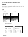
Appendix B: INTERFACE SPECIFICATIONS
Introduction
This appendix presents the interface specifications of I/O ports for the printer. These specifications
include pin assignments, protocols and detailed information about how to properly interface your
printer with your host or terminal.
Serial
Pin Configuration
The RS-232 connector on the printer side is a female, DB-9.
Pin
1
2
3
4
5
6
7
8
9
Direction
Tied to in 6
In
Out
Tied to pin 1
Out
In
Out
Definition
Not used
Receive Data (RxData)
Transmit Data (TxData)
No connection
Logic Ground
Not used
Request to Send (RTS)
Clear to Send (CTS)
+5V
Note: Pin 9 is reserved for Keyboard Device Unit (KDU) only, do not connect this pin if you are
using a general host like a PC.
Connection with host:
Host 25S
(PC or compatible)
Printer 9P
Host 9S
Printer 9P
(PC or compatible)
DTR 20
DSR 6
TX 2
RX 3
CTS 5
RTS 4
GND 7
1
6
2 RX
3 TX
7 RTS
8 CTR
5 GND
DTR 4
DSR 6
TX 3
RX 2
CTS 8
RTS 7
GND 5
User's Guide 52
-----------------------------------------------------------------------
-----------------------------------------------------------------------
1
6
2 RX
3 TX
7 RTS
8 CTS
5 GND
Three Wire connection:
This method is the simplest method of connecting the printer to a host or terminal. This method
requires Software Protocol Handshaking (Xon/Xoff flow control).
Host 25S
Printer 9P
(PC or compatible)
Host 9S
(PC or compatible)
Printer 9P
TX 2
RX 3
GND 7
pin 4
pin 5
pin 6
pin 20
TX 3
RX 2
GND 5
pin 4
pin 6
pin 7
pin 8
2 RX
3 TX
5 GND
----------- 2 RX
----------- 3 TX
----------- 5 GND
-------------------------------
Serial port Set-up Parameters
Baud rate: 2400, 4800, 9600, 19200 and 38400.
Baud rate set-up parameters are programmable by software commands only.
Data bits: 8 data bits, 1 start bit and 1 stop bit.
Parity bit: None
Handshaking: XON/XOFF (software flow control) and CTS/RTS (hardware flow control).
Before trying to print with applications verify that the Windows Printer Driver and the serial
port communications parameters are checked. You should also set the flow control to
“Xon/Xoff” or “Hardware”.
User's Guide 53
Parallel (Centronics)
Pin Configuration
The parallel port is a standard 36-pin Centronics.
Pin
1
2
3
4
5
6
7
8
9
10
11
12
Direction
In
In
In
In
In
In
In
In
In
Out
Out
Out
Definition
/STROBE
Data 1
Data 2
Data 3
Data 4
Data 5
Data 6
Data 7
Data 8
/ACK
BUSY
PE
Pin
13
14,15
16
17
18
19 to 30
31
32
33 to 36
Direction Definition
Out
SELECT
NC
Ground
Ground
NC
Ground
NC
Out
/Fault
NC
Auto Polling
Both the serial and parallel ports are active at the same time on this printer. Data can be received on
either one, however no provision is made for port contention. If data is transmitted to both ports
simultaneously, it will cause the data in the received buffer to be corrupted.
User's Guide 54
Appendix C: ASCII TABLE
0
0
NUL
1
SOH
2
STX
1
XON
XOFF
3
4
NAK
5
2
3
4
5
6
7
0
@
P
`
p
!
1
A
Q
a
q
“
2
B
R
b
r
#
3
C
S
c
s
$
4
D
T
d
t
%
5
E
U
e
u
6
ACK
&
6
F
V
f
v
7
BEL
‘
7
G
W
g
w
8
BS
(
8
H
X
h
x
)
9
I
Y
i
y
*
:
J
Z
j
z
+
;
K
[
k
{
9
A
LF
ESC
B
C
FF
,
<
L
\
l
|
D
CR
-
=
M
]
m
}
E
SO
RS
.
>
N
^
n
~
F
SI
US
/
?
O
_
o
DEL
User's Guide 55
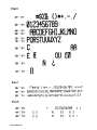
Appendix D: FONTS AND BAR CODES FOR THE
PPLA Emulation
Internal Fonts
Note: The fonts in the following tables are relative sizes and formatted for this manual. The
actual printed font size may be different.
Fonts 0 to 8 have single symbol set.
User's Guide 56
User's Guide 57
User's Guide 58
Font 9
This font is an ASD smooth font set and can be printer using 8 symbol sets: USASCII, UK, German,
French, Italian, Spanish, Swedish, and Danish/Norwegian.
Font 9 can be printed in point sizes of 4, 6, 8, 10, 12, 14 and 18. The 4-point font is only available in
the FM403TT model.
User's Guide 59
User's Guide 60
Courier Font Set
The Courier font set is for the models FM402DT and FM402TT only. It includes Roman-8, PC, PCA, PC-B, EAMA-94, Legal, Greek and Russian symbol sets.
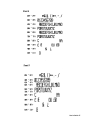
User's Guide 61
User's Guide 62
User's Guide 63
User's Guide 64
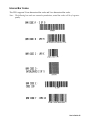
Internal Bar Codes
This PPLA supports 20 one-dimensional bar codes and 2 two dimensional bar codes.
Note: The following bar codes are scanned reproductions, actual bar codes will be of a greater
quality.
User's Guide 65
User's Guide 66
User's Guide 67
User's Guide 68
Appendix E: FONTS AND BAR CODES FOR PPLB
Emulation
Internal Fonts
There are 5 internal fonts for the PPLB emulation.
Each has 6 eight-bit and 9 seven-bit symbol sets. Font 5 does not contain any lower-case characters.
8 bit symbol sets
7 bit symbol sets
code page 437, 850, 852, 860, 863 and 865
USA, British, German, French, Danish, Italian,
Spanish, Swedish and Swiss
User's Guide 69
Symbol Set
User's Guide 70
User's Guide 71
User's Guide 72
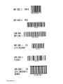
Internal Bar Codes
The PPLB supports 26 one-dimensional bar codes and 2 two dimensional bar codes.
User's Guide 73
User's Guide 74
AMT Datasouth Corp.
Corporate Headquarters
4765 Calle Quetzal
Camarillo, CA 93012
(805) 388-5799 PH
(805) 484-5282 FX
Charlotte Operation
4216 Stuart Andrew Blvd.
Charlotte, NC 28217
(704) 523-8500 PH
(704) 525 6104 FX
www.amtdatasouth.com
AMT Datasouth International
Unit B, Pinnacle 15
Gowerton Rd, Brackmills
Northampton, NN4 7BW
England
+44 1604 763394 PH
+44 1604 760661 FX