1
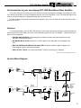
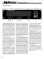
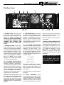
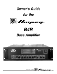
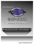
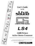
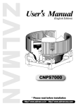
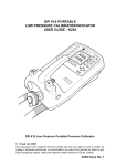
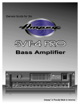
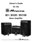
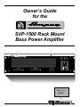
Owner’s Guide for the SVP-1500 Rack Mount Bass Power Amplifier @@@@@@@@@@@@@@@@@@@@@@@@@@@@@@@@@@@@ ÀÀÀÀÀÀÀÀÀÀÀÀÀÀÀÀÀÀÀÀÀÀÀÀÀÀÀÀÀÀÀÀÀÀÀÀ ;;;;;;;;;;;;;;;;;;;;;;;;;;;;;;;;;;;; yyyyyyyyyyyyyyyyyyyyyyyyyyyyyyyyyyyy @@@@@@@@@@@@@@@@@@@@@@@@@@@@@@@@@@@@ ÀÀÀÀÀÀÀÀÀÀÀÀÀÀÀÀÀÀÀÀÀÀÀÀÀÀÀÀÀÀÀÀÀÀÀÀ ;;;;;;;;;;;;;;;;;;;;;;;;;;;;;;;;;;;; yyyyyyyyyyyyyyyyyyyyyyyyyyyyyyyyyyyy @@@@@@@@@@@@@@@@@@@@@@@@@@@@@@@@@@@@ ÀÀÀÀÀÀÀÀÀÀÀÀÀÀÀÀÀÀÀÀÀÀÀÀÀÀÀÀÀÀÀÀÀÀÀÀ ;;;;;;;;;;;;;;;;;;;;;;;;;;;;;;;;;;;; yyyyyyyyyyyyyyyyyyyyyyyyyyyyyyyyyyyy @@@@@@@@@@@@@@@@@@@@@@@@@@@@@@@@@@@@ ÀÀÀÀÀÀÀÀÀÀÀÀÀÀÀÀÀÀÀÀÀÀÀÀÀÀÀÀÀÀÀÀÀÀÀÀ ;;;;;;;;;;;;;;;;;;;;;;;;;;;;;;;;;;;; yyyyyyyyyyyyyyyyyyyyyyyyyyyyyyyyyyyy @@@@@@@@@@@@@@@@@@@@@@@@@@@@@@@@@@@@ ÀÀÀÀÀÀÀÀÀÀÀÀÀÀÀÀÀÀÀÀÀÀÀÀÀÀÀÀÀÀÀÀÀÀÀÀ ;;;;;;;;;;;;;;;;;;;;;;;;;;;;;;;;;;;; yyyyyyyyyyyyyyyyyyyyyyyyyyyyyyyyyyyy @@@@@@@@@@@@@@@@@@@@@@@@@@@@@@@@@@@@ ÀÀÀÀÀÀÀÀÀÀÀÀÀÀÀÀÀÀÀÀÀÀÀÀÀÀÀÀÀÀÀÀÀÀÀÀ ;;;;;;;;;;;;;;;;;;;;;;;;;;;;;;;;;;;; yyyyyyyyyyyyyyyyyyyyyyyyyyyyyyyyyyyy @@@@@@@@@@@@@@@@@@@@@@@@@@@@@@@@@@@@ ÀÀÀÀÀÀÀÀÀÀÀÀÀÀÀÀÀÀÀÀÀÀÀÀÀÀÀÀÀÀÀÀÀÀÀÀ ;;;;;;;;;;;;;;;;;;;;;;;;;;;;;;;;;;;; yyyyyyyyyyyyyyyyyyyyyyyyyyyyyyyyyyyy @@@@@@@@@@@@@@@@@@@@@@@@@@@@@@@@@@@@ ÀÀÀÀÀÀÀÀÀÀÀÀÀÀÀÀÀÀÀÀÀÀÀÀÀÀÀÀÀÀÀÀÀÀÀÀ ;;;;;;;;;;;;;;;;;;;;;;;;;;;;;;;;;;;; yyyyyyyyyyyyyyyyyyyyyyyyyyyyyyyyyyyy 10 A M P SIGNAL LIMIT PROTECT SIGNAL LIMIT PROTECT RESET Made in the U.S.A. by SVP-1500 Bass Amplifier Table of Contents Important Safeguards and Precautions . . . . . . . . . . . .2 Introduction . . . . . . . . . . . . . . . . . . . . . . . . . . . . . . . .3 Features . . . . . . . . . . . . . . . . . . . . . . . . . . . . . . . . . . .3 System Block Diagram . . . . . . . . . . . . . . . . . . . . . . . .3 The Front Panel . . . . . . . . . . . . . . . . . . . . . . . . . . . . .4 The Rear Panel . . . . . . . . . . . . . . . . . . . . . . . . . . . . .5 Operation Stereo/Bridged Mono/Parallel Mono Modes . . . . .6 Input/Output Connectors . . . . . . . . . . . . . . . . . . .6 Installations Stereo . . . . . . . . . . . . . . . . . . . . . . . . . . . . . . . . .7 Bridged Mono . . . . . . . . . . . . . . . . . . . . . . . . . . .7 Biamp . . . . . . . . . . . . . . . . . . . . . . . . . . . . . . . . .7 Technical Specifications . . . . . . . . . . . . . . . .back cover Important Safeguards and Precautions All Ampeg products are designed for continuous safe operation, as long as common sense is used and steps are taken to help avoid certain problems. Abiding by the following rules can help prevent damage to your amplifier, yourself and others. • The amplifier is equipped with a three-pronged AC power cord. To reduce the risk of electrical shock, NEVER remove or otherwise attempt to defeat the ground pin of the power cord. • Connect the amplifier ONLY to a properly grounded AC outlet of the proper voltage for your amp. • Avoid sudden temperature extremes, rain and moisture. Also, avoid sudden and intense impact. (If the unit has been subjected to any of the preceding abuses, have it looked at by an authorized service center.) • NEVER set the amplifier on a support that might give out under its weight. • Always keep the total speaker impedance at or above the rated load. • Unplug the amplifier before cleaning it. NEVER spray liquid cleaners onto the amplifier. Wipe it with a slightly dampened, lintfree cloth to remove dirt and film. • Don’t use the amplifier if it has sustained damage to the chassis, controls, or power cord. Refer the unit to an authorized service center for inspection. • Amplifiers capable of producing high volume levels are also capable of inflicting permanent hearing loss or damage, if the exposure to such levels is prolonged. Such damage is progressive and irreversible! The chart below shows the U.S. Government Occupational Safety and Health Administration (OSHA) regulations which were in effect at the time of this publication for permissible noise exposure, per 29CRF1910, Table G-16. SOUND LEVEL dBA SLOW RESPONSE DURATION PER DAY IN HOURS SOUND LEVEL dBA SLOW RESPONSE DURATION PER DAY IN HOURS 90 92 95 97 100 8 6 4 3 2 102 105 110 115 1-1/2 1 1/2 1/4 or less According to OSHA, any exposure in excess of those listed above could result in some hearing loss. CAUTION ATTENTION VORSICHT RISK OF ELECTRIC SHOCK DO NOT OPEN RISQUE D'ELECTROCUTION NE PAS OUVRIR ELEKTRISCHE SCHLAGGEFAHR NICHT OFFENEN CAUTION: TO REDUCE THE RISK OF ELECTRIC SHOCK, DO NOT REMOVE COVER. NO USER-SERVICEABLE PARTS INSIDE. REFER SERVICING TO QUALIFIED SERVICE PERSONNEL. ATTENTION: POUR REDUIRE D'ELECTROCUTION NE PAS ENLEVER LE COUVERCLE. AUCUNE PIECE INTERNE N'EST REPRABLE PAR L'UTILISATEUR. POUR TOUTE REPARATION, S'ADRESSER A UN TECHNICIEN QUALIFIE. VORSICHT: ZUR MINIMIERUNG ELEKTRISCHER SCHLAGGEFAHR NICHT DEN DECKEL ABENHMEN. INTERNE TEILE KONNEN NICHT VOM BENUTZER GEWARTET WERDEN. DIE WARTUNG IS QUALIFIZIERTEM WARTUNGSPERSONAL ZU UBERLASSEN. THIS EQUIPMENT HAS BEEN DESIGNED AND ENGINEERED TO PROVIDE SAFE AND RELIABLE OPERATION. IN ORDER TO PROLONG THE LIFE OF THE UNIT AND PREVENT ACCIDENTAL DAMAGES OR INJURY, PLEASE FOLLOW THESE PRECAUTIONARY GUIDELINES: CAUTION: TO REDUCE THE RISK OF ELECTRIC SHOCK, DO NOT OPEN CHASSIS; DO NOT DEFEAT OR REMOVE THE GROUND PIN OF THE POWER CORD; CONNECT ONLY TO A PROPERLY GROUNDED AC POWER OUTLET. WARNING: TO REDUCE THE RISK OF FIRE OR ELECTRIC SHOCK, DO NOT EXPOSE THIS EQUIPMENT TO RAIN OR MOISTURE. CAUTION: NO USER-SERVICEABLE PARTS INSIDE. REFER SERVICING TO QUALIFIED SERVICE PERSONNEL. CAUTION: OUR AMPLIFIERS ARE CAPABLE OF PRODUCING HIGH SOUND PRESSURE LEVELS. CONTINUED EXPOSURE TO HIGH SOUND PRESSURE LEVELS CAN CAUSE PERMANENT HEARING IMPAIRMENT OR LOSS. USER CAUTION IS ADVISED AND EAR PROTECTION IS RECOMMENDED IF UNIT IS OPERATED AT HIGH VOLUME. 2 EXPLANATION OF GRAPHICAL SYMBOLS: "DANGEROUS VOLTAGE" = "DANGER HAUTE TENSION" "GEFAHLICHE SPANNUNG" "IT IS NECESSARY FOR THE USER TO REFER TO THE INSTRUCTION MANUAL" = "REFERREZ-VOUS AU MANUAL D'UTILISATION" "UNBEDINGT IN DER BEDIENUNGSANLEITUNG NACHSCHLAGEN" SVP-1500 Bass Amplifier An Introduction to your new Ampeg SVP-1500 Rack Mount Bass Amplifier First of all, thank you for choosing one of the finest rack mount bass amplifiers available, the Ampeg SVP-1500. Your new bass amp offers you many outstanding features, such as a rated output of up to 780 watts per channel into 2 ohms, forced fan cooling and a highly-advanced, built-in protection circuit. In order to achieve the highest performance and longest life from your new bass amp, please read this owner’s guide prior to its use. Features In true Ampeg tradition, your new SVP-1500 offers you more power, performance and ease of operation than any other bass amp in its class. Below are some of the outstanding features of your new amplifier – features which set it apart from the competition! • RUGGED AND PORTABLE: Ampeg’s legendary reliability and three-rack-space design fit into most any audio reinforcement system. • BALANCED INPUT JACKS: Balanced 1/4” phone jacks for use with high or low impedance signals. • BUILT-IN LIMITING AND PROTECTION CIRCUITRY: Automatic protection against clipping, overload conditions, short circuits and overheating. • DUAL OUTPUT JACKS: 1/4” phone and Speakon® jacks for connecting your speakers. *NOTE: 1/4” jacks not available in some areas. System Block Diagram A INPUTS SIGNAL FAULT A OUTPUTS A SENSITIVITY 1+ LIMITER POWER AMP 1- 22+ SPEAKON® JACK (A) LIMIT PROTECTION 1+ STEREO 1- MONO BRIDGE SIGNAL B INPUTS 22+ FAULT SPEAKON® JACK (MONO BRIDGE/ BIAMP) B OUTPUTS B SENSITIVITY LIMITER POWER AMP 1+ 1- 22+ LIMIT SPEAKON® JACK (B) PROTECTION 3 SVP-1500 Bass Amplifier The Front Panel 1 7 @@@@@@@@@@@@@@@@@@@@@@@@@@@@@@@@@@@@ ÀÀÀÀÀÀÀÀÀÀÀÀÀÀÀÀÀÀÀÀÀÀÀÀÀÀÀÀÀÀÀÀÀÀÀÀ ;;;;;;;;;;;;;;;;;;;;;;;;;;;;;;;;;;;; yyyyyyyyyyyyyyyyyyyyyyyyyyyyyyyyyyyy @@@@@@@@@@@@@@@@@@@@@@@@@@@@@@@@@@@@ ÀÀÀÀÀÀÀÀÀÀÀÀÀÀÀÀÀÀÀÀÀÀÀÀÀÀÀÀÀÀÀÀÀÀÀÀ ;;;;;;;;;;;;;;;;;;;;;;;;;;;;;;;;;;;; yyyyyyyyyyyyyyyyyyyyyyyyyyyyyyyyyyyy @@@@@@@@@@@@@@@@@@@@@@@@@@@@@@@@@@@@ ÀÀÀÀÀÀÀÀÀÀÀÀÀÀÀÀÀÀÀÀÀÀÀÀÀÀÀÀÀÀÀÀÀÀÀÀ ;;;;;;;;;;;;;;;;;;;;;;;;;;;;;;;;;;;; yyyyyyyyyyyyyyyyyyyyyyyyyyyyyyyyyyyy @@@@@@@@@@@@@@@@@@@@@@@@@@@@@@@@@@@@ ÀÀÀÀÀÀÀÀÀÀÀÀÀÀÀÀÀÀÀÀÀÀÀÀÀÀÀÀÀÀÀÀÀÀÀÀ ;;;;;;;;;;;;;;;;;;;;;;;;;;;;;;;;;;;; yyyyyyyyyyyyyyyyyyyyyyyyyyyyyyyyyyyy @@@@@@@@@@@@@@@@@@@@@@@@@@@@@@@@@@@@ ÀÀÀÀÀÀÀÀÀÀÀÀÀÀÀÀÀÀÀÀÀÀÀÀÀÀÀÀÀÀÀÀÀÀÀÀ ;;;;;;;;;;;;;;;;;;;;;;;;;;;;;;;;;;;; yyyyyyyyyyyyyyyyyyyyyyyyyyyyyyyyyyyy @@@@@@@@@@@@@@@@@@@@@@@@@@@@@@@@@@@@ ÀÀÀÀÀÀÀÀÀÀÀÀÀÀÀÀÀÀÀÀÀÀÀÀÀÀÀÀÀÀÀÀÀÀÀÀ ;;;;;;;;;;;;;;;;;;;;;;;;;;;;;;;;;;;; yyyyyyyyyyyyyyyyyyyyyyyyyyyyyyyyyyyy @@@@@@@@@@@@@@@@@@@@@@@@@@@@@@@@@@@@ ÀÀÀÀÀÀÀÀÀÀÀÀÀÀÀÀÀÀÀÀÀÀÀÀÀÀÀÀÀÀÀÀÀÀÀÀ ;;;;;;;;;;;;;;;;;;;;;;;;;;;;;;;;;;;; yyyyyyyyyyyyyyyyyyyyyyyyyyyyyyyyyyyy @@@@@@@@@@@@@@@@@@@@@@@@@@@@@@@@@@@@ ÀÀÀÀÀÀÀÀÀÀÀÀÀÀÀÀÀÀÀÀÀÀÀÀÀÀÀÀÀÀÀÀÀÀÀÀ ;;;;;;;;;;;;;;;;;;;;;;;;;;;;;;;;;;;; yyyyyyyyyyyyyyyyyyyyyyyyyyyyyyyyyyyy SIGNAL LIMIT PROTECT 2 3 4 1: FRONT PANEL EXHAUST VENT: The SVP-1500 employs a variablespeed internal cooling fan to draw air through the unit to keep it running cool even under extreme operating conditions. The air is drawn in through the unit's rear intake vent (#11) and is forced out through the front panel exhaust vent. This method of cooling draws air out from the interior of the rack and provides more efficient cooling than methods which bring air in from the front and exhaust it through the back. Keep this vent clear and free from obstruction at all times to insure proper cooling. 2: SIGNAL INDICATOR LED: This LED will illuminate when signal is detected at the amplifier's output terminals, providing accurate visual confirmation of signal presence, often helpful in hookup and troubleshooting. The level of the signal must be at about 5% of the amplifier's full rated output to make the LED glow. 3: LIMIT INDICATOR LED: The SVP-1500 employs an internal "Automatic" limit circuit to prevent amplifier "clipping". The Limit LED will illuminate whenever the input signal attempts to overdrive the amplifier's output section, indicating that the Limiter has been called upon to prevent clipping. (Not only does clipping 4 SIGNAL 2 LIMIT PROTECT 3 4 produce harsh sounding distortion, it is also capable of damaging speaker components - particularly high frequency drivers.) Periodic flashing of the Limit LED indicates operation at or near full output and is no cause for alarm. Steady illumination of the LED indicates constant operation of the Limiter, with the possibility that the input signal should be reduced by means of the Sensitivity control (#13). The Limiter within the SVP-1500 is fully automatic, with no defeat switch, insuring complete protection against clipping at all times. 4: PROTECT INDICATOR LED: This LED will illuminate whenever the internal protection relay on either channel is activated, indicating the possibility of overheating, DC voltage at the outputs, overloads or short circuits. The protection relay is activated for a short period upon initial turn-on and at turn-off to prevent transient "spikes" from being reproduced through your speakers. If the limit and protect indicators for a channel cycle on and off with a signal applied, this indicates the presence of a short circuit or load impedance less than 2 ohms on the output of that channel (less than 4 ohms in the bridged mono mode). In this case, check all wiring for shorts, check the total connected load impedance to be sure it is 10 A M P RESET 5 6 not below the amplifier ratings, or check for other potential problems. 5: POWER INDICATOR LED: This LED will illuminate when AC power is applied by means of the Power switch (#7). If the LED fails to illuminate, check the AC outlet or the circuit breaker on the front panel (#6). 6: RESET SWITCH: The SVP-1500 employs an AC line circuit breaker to help protect against damages due to excessive current demands. If the amplifier does not function, check the circuit breaker. If it has opened, the button will be protruding and showing a contrasting color. You may reset it by pressing the button in until it latches. The circuit breaker must cool down for a short time before the button will latch. If the circuit breaker opens repeatedly with no signal input, have the amplifier checked by a qualified service person. 7: POWER SWITCH: This switch turns the amplifier On in the Up position and Off in the down position. When AC power is applied to the amplifier, the Power LED indicator (#5) will illuminate. SVP-1500 Bass Amplifier The Rear Panel 8 9 9 9 11 MODEL: SERIAL: LINE: WATTS: SVP-1500 SVP15OOU12B 120 V ~ 60 Hz 1500 MAX STEREO MONO MODE 10 8: POWER CORD: This heavy duty power cord must be connected to a grounded AC outlet of the proper voltage for the amplifier to operate. IN ORDER TO AVOID THE POSSIBILITY OF ELECTRIC SHOCK, DO NOT REMOVE OR BYPASS THE GROUND PRONG OF THE POWER CORD. 9: SPEAKON® JACKS: These heavyduty output jacks offer an excellent method of connecting the amplifier to your speakers using cables terminated with Speakon® type plugs. Use of these connectors is highly recommended under high power operation. When using the amplifier in the Mono Mode, you MUST use the middle Speakon® jack. Please refer to pages 6 and 7 for more information. 10 12 11: FAN INTAKE AREA: The internal cooling fan is mounted directly behind this cover, drawing cooling air into the amplifier to help prevent it from running hot. This area must be kept free from obstruction! Check the Intake Area periodically and remove any foreign materials if needed. 12: 1/4" PHONE JACK INPUTS: These jacks accept line level signal sources by means of cables fitted with standard 1/4" phone plugs. Low impedance balanced or unbalanced, as well as high impedance sources, are acceptable for these inputs. Low impedance balanced inputs are to be wired as follows: Tip: Signal + Ring: Signal - 10: 1/4" PHONE JACK OUTPUTS: These additional output jacks offer an alternative method of connecting to your speakers, using cables terminated with 1/4" phone plugs. Since these jacks are not as well suited to high current applications as the Speakon® jacks, they are NOT recommended for extended use at high power levels, or when driving 2 or 4 ohm loads. The input channel circuitry is transformerless electronically balanced, and requires a line level signal of 1.5V RMS or greater to drive the amplifier to full output. NOTE: In some areas 1/4” jacks are not acceptable for use on amplifiers capable of high output power levels. For this reason the 1/4” jacks on your amplifier may be sealed – use ONLY the Speakon® jacks for connecting your speakers. 13: LEVEL CONTROLS: These rotary potentiometers control the level or gain of each channel, with the fullyclockwise position of each providing maximum sensitivity. Normal calibration of the SVP-1500 to a mixer would Sleeve: Ground 13 14 13 12 cause the Limit LED to flash at the same time that the mixer's VU meters indicate full output, or "OVU." In the Mono Mode, use the Channel A Level control. 14: MONO / STEREO MODE SWITCH: This push/push switch selects the operating mode of the amplifier. In the "out" position the amplifier is in the Stereo Mode; with the switch in the "in" position the amplifier is in the Mono Mode. In the Mono Mode, Channel A functions as the input channel; Channel B inputs will be disconnected. NOTE: Caution should be exercised! Improper hookup or misuse of the Mode switch could cause damage to speakers. See the specific hookup configurations on pages 6 and 7. In the Mono Mode, use the Channel A input jack. 5 SVP-1500 Bass Amplifier Operation Stereo Mode: The SVP-1500 can be used in the Stereo Mode as two separate amplifier units, each capable of driving loads down to 2 ohms. Each channel operates independently and has its own input connectors, sensitivity level controls, signal indicator LEDS, automatic limiter, fault protection circuitry, power amp, and speaker outputs. In the Stereo Mode, the Mono/Stereo switch (#14 on the rear panel) must be in the OUT position. Connections to your speakers can be made with either the 1/4” jacks* or the Channel A and B Speakon® jacks (or both since they are wired in parallel). See the illustration labeled “Stereo Operation” on the facing page. Bridged Mono Mode: The two power amplifiers can be bridged together to form a single, higher-powered amp. In the Bridged Mono Mode, the amplifier uses Channel A's input jacks and Sensitivity control; Channel B's are disconnected. Channel B's power amp receives its signal from a tap after Channel A's Sensitivity control, but prior to Channel B's Limiter, so each channel is independently protected. To select the Mono Mode, the Mono/Stereo switch (#14 on the rear panel) must be in the IN position. Because both channels are being used (bridged in series), the minimum speaker load impedance must be 4 ohms. Connections to your speakers must be made with the Mono Bridge (middle) Speakon® jack. See the illustration labeled “Bridged Mono Mode Operation” on the facing page. Biamp Mode: The SVP-1500 can be used to separately power the lows and highs of a cabinet with biamp inputs or a separate low and high frequency cabinet. For Biamp Operation, the Mono/Stereo switch (#14 on the rear panel) must be in the OUT (stereo) position. Connections to your speakers can be made with either the 1/4” jacks* of the Mono Bridge (middle) Speakon® jack. We suggest using Channel A for the low frequencies and Channel B for the highs. When using a single cabinet with a Speakon® Biamp Input jack, terminate the end of the speaker cable going to the cabinet with a single Speakon® connector. (Wire the connector according to the pinouts on the cabinet’s input jackplate label or in its owners manual). If the cabinet has 1/4” Biamp Low and Biamp High Input jacks, or when using separate cabinets for lows and highs, the end of the speaker cable going to the cabinet must be terminated with two 1/4” connectors – one for the highs, one for the lows. (A pigtail connector and/or other adapters may be used to split the low and high speaker wires going to the cabinets.) See the illustration labeled “Stereo Operation” on the facing page. Input Connectors: The SVP-1500 uses balanced 1/4" phone jacks as input connectors. These inputs accept High or Low impedance and balanced or unbalanced signals. A "stereo" 1/4" plug (ring/tip/sleeve) must be used to feed a high impedance balanced signal into the amplifier. In the Mono Mode, Channel A’s input jack is used; Channel B's input jack is disconnected. Speaker Output Connectors: Each channel of the SVP-1500 has both a 1/4" phone jack* and a Speakon® jack. A third Speakon® jack is provided for Mono Bridged use. The Speakon® jacks are more reliable for extended use at high power levels, and their use is always recommended over the 1/4” phone jacks. On each channel, the Channel A and B Speakon® jacks are wired in parallel with the 1/4" phone jacks: the tip of the 1/4" jack is connected to pin 1+ of the Speakon® jack and the sleeve is connected to pin 1–. Use of both the 1/4" jack and the Speakon® jacks simultaneously to connect two cabinets in parallel is possible, providing proper polarity is observed. The SVP-1500’s Mono Bridge (middle) Speakon® jack is wired as follows: Pins 1+ and 1– = Channel B+ and – respectively; pins 2+ and 2– = Channel A + and – respectively. *NOTE: 1/4” jacks not available in some areas. 6 SVP-1500 Bass Amplifier Installations Stereo Operation: MODEL: SVP-1500 SERIAL: SVP15OOU12B LINE: 120 V ~ 60 Hz WATTS: 1500 MAX Right Cabinet Left Cabinet STEREO MONO MODE OUT (STEREO) From Speakon® Jacks From Preamp's Right Out From Preamp's Left Out From 1/4" Jacks* Bridged Mono Mode Operation: High Power Cabinet MODEL: SVP-1500 SERIAL: SVP15OOU12B LINE: 120 V ~ 60 Hz WATTS: 1500 MAX STEREO MONO MODE IN (MONO) From Preamp's Main Out From Bridged Mono/Biamp Speakon® Jack WARNING! Due to higher power output per speaker, use caution in setting levels. Biamp Operation: Biamp Cabinet or Low and High Cabinets** MODEL: SVP-1500 SERIAL: SVP15OOU12B LINE: 120 V ~ 60 Hz WATTS: 1500 MAX **May require pigtail connectors or other adapters – see cabinet(s) for pin configurations and other considerations. HF Cab STEREO MONO MODE OUT From Bridged Mono/Biamp Speakon® Jack From (STEREO) From Crossover's Crossover's HIGH OUT LOW OUT To Biamp Input Speakon® Jack IN LF Cab To HIGH IN/HF cabinet To LOW IN/LF cabinet From CH.B 1/4" jack* From CH.A 1/4" jack* IN PINS 2+,2– PINS 1+,1– From Amp's Bridged Mono/ Biamp Jack *NOTE: 1/4" jacks not available in some areas. 7 SVP-1500 Bass Amplifier Technical Specifications POWER OUTPUTS (per channel, stereo mode)1,2 8 ohms: 4 ohms: 2 ohms: 2 ch (20-20kHz) 2 ch 1kHz 230 watts 260 watts 425 watts 560 watts 2 ch 40Hz (1 cycle) 280 watts 480 watts 780 watts 1 ch 1 kHz 295 watts 500 watts 750 watts 1 ch 40Hz (1 cycle) 300 watts 550 watts 900 watts POWER OUTPUTS (mono mode)1,2 16 ohms: 8 ohms: 4 ohms: 20-20kHz 460 watts 1kHz 520 watts 850 watts 1120 watts FREQUENCY RESPONSE 40Hz (1 cycle) 560 watts 960 watts 1560 watts +0, -.8dB / 20Hz - 20kHz @ 230 W / channel @ 8 ohms TOTAL HARMONIC DISTORTION Less than .25%, 20Hz - 20kHz @230 W / channel @ 8 ohms SLEW RATE1 30 volts / microsecond (stereo mode), 60 volts / microsecond (mono mode) SIGNAL TO NOISE RATIO1,2 Greater than -100dB from 230 watts / 8 ohms INPUT TYPE AND IMPEDANCE Transformerless electronically balanced, 20K actual load impedance. Suitable for Low or High-Z balanced line. One (1) 1/4” phone jack per channel. INPUT SENSITIVITY 1.5 V RMS for 230 Watts / 8 ohms LOAD IMPEDANCE Stereo Mode: 2 ohms or greater; Bridged Mono Mode: 4 ohms or greater DAMPING FACTOR1 Typical 250 (1kHz, 8 ohms) OUTPUT CONNECTIONS 1/4” phone jack*, plus Speakon® jacks each channel; Speakon® jack for Mono Bridge/Biamp PROTECTION CIRCUITRY Short circuit, RF burnout, overtemp, turn on/off transient and DC protection, Speaker protection relays, built-in auto limiter (Anti-clip) COOLING Forced air fan cooling, rear intake, front exhaust POWER REQUIREMENTS 115VAC 60Hz, 880VA 100/110VAC 50/60Hz, 880VA 230VAC, 50/60Hz, 880VA CIRCUIT BREAKER 10 amp (mains) SIZE AND WEIGHT 19” W x 5.25” H x 12.5” D; 33 lbs. 483mm x 133mm x 317mm; 15Kg. typical performance 1 @115 VAC 60Hz 2 *NOTE: 1/4” jacks not available in some areas. Ampeg reserves the right to change specifications without notice. Ampeg is proudly Made in America. ©1996 SLM Electronics, 1400 Ferguson Avenue, St. Louis, MO 63133 U.S.A. P/N 47-655-12 . 03/97