1
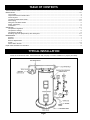
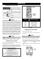
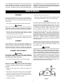
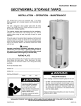
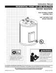
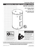
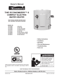
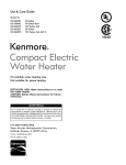
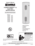
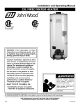
SOLAR WATER HEATER
Instruction Manual
INSTALLATION • OPERATION • MAINTENANCE
The Solar Water Heater has been sold as a component part. It
has been factory equipped with a booster element, and
thermostat with high limit.
The solar water heater is designed to store potable water within
the limits listed on the rating plate and to supply domestic hot
water up to the element’s heating capability.
This manual contains basic instructions for the installation,
operation and maintenance of the solar water heater only. Read
it carefully before using the solar tank, then keep it handy for
quick reference.
If the tank leaks or the element fails to operate, all technical and
warranty questions should be directed to the local dealer from
whom the solar water heater was purchased. If you are
unsuccessful, please write to the company listed on the warranty
sheet which came with the solar water heater.
WARNING
Improper installation, adjustment, alteration, service or
maintenance can cause injury or property damage. Refer to
this manual. For assistance or additional information consult
a qualified installer, service agency or the local utility.
RATING PLATE
A rating plate identifying the solar water heater will be found
above the drain valve. When referring to the solar water heater,
always have the information listed on the rating plate readily
available.
Fill in that information here:
MODEL NO. _______________________________________
SERIAL NO. _______________________________________
WARNING
INSTALLATION DATE: ________________________________
Month
Day
Year
INSULATING JACKETS:
When installing an external insulation jacket on the solar
water heater:
• DO NOT cover the temperature-pressure relief valve.
• DO NOT cover the instruction manual. Keep it on the
side of the water heater or nearby for future reference.
• DO obtain new warning and instruction labels from
the manufacturer for placement on the blanket directly
over the existing labels.
Failure to follow these instructions can result in fire,
serious personal injury or death.
THE MANUFACTURER OF THIS SOLAR WATER HEATER WILL NOT BE LIABLE FOR ANY DAMAGE DUE TO FAILURE TO FOLLOW
THESE INSTALLATION AND OPERATING INSTRUCTIONS.
PRINTED 0310
11
317365-002
TABLE OF CONTENTS
TYPICAL INSTALLATION .................................................................................................................................................................. 2
INSTALLATION ............................................................................................................................................................................... 3-5
Local Codes .............................................................................................................................................................................. 3
Temperature-Pressure Relief Valve .......................................................................................................................................... 3
Closed System .......................................................................................................................................................................... 3
Locating the Solar Water Heater ............................................................................................................................................ 3-4
Water Piping ........................................................................................................................................................................... 4-5
Filling the Solar Water Heater ................................................................................................................................................... 5
Wiring of Elements .................................................................................................................................................................... 5
Thermostat ................................................................................................................................................................................ 5
OPERATION ................................................................................................................................................................................... 6-7
Temperature Regulation ........................................................................................................................................................... 7
Temperature Settings ............................................................................................................................................................... 6
Temperature Adjusting .............................................................................................................................................................. 6
Resetting High Limit (Temperature) Shut Off System ........................................................................................................... 6-7
MAINTENANCE .............................................................................................................................................................................. 7-8
Draining ..................................................................................................................................................................................... 7
Element ..................................................................................................................................................................................... 7
Element Replacement .............................................................................................................................................................. 7
Anode ..................................................................................................................................................................................... 7-8
Water Heater Sounds ............................................................................................................................................................... 8
Repair Parts Illustration and Schedule ............................................................................................................................................ 8
TYPICAL INSTALLATION
Check all connections for leaks. Consult the local utility company to examine installation for propriety and safety.
FIGURE 1
2
INSTALLATION
WARNING
WARNING
Never operate the electrical heating element without being certain
the solar water heater is completely filled with water. If any air is
left in the top of the tank, the heating element will burn out.
The temperature-pressure relief valve should be manually
opened once a year. Caution should be taken to ensure that
(1) no one is in front of or around the outlet of the temperaturepressure relief valve discharge line, and (2) the water manually
discharged will not cause any bodily injury or property damage
because the water may be extremely hot.
LOCAL CODES
The installation of solar water heater must be in accordance with
these instructions and all applicable local codes and electric utility
requirements. In the absence of local codes, install in accordance
with the latest edition of the National Electrical Code (NFPA-70).
If after manually operating the valve, it fails to completely reset
and continues to release water, immediately close the cold water
inlet to the water heater, follow the draining instructions, and
replace the temperature-pressure relief valve with a new one.
TEMPERATURE-PRESSURE RELIEF VALVE
WARNING
If the temperature-pressure relief valve on the appliance weeps
this may be due to thermal expansion. The water supply serving
this solar water heater may have a check valve installed. Contact
the water supplier or local plumbing contractor on how to control
this situation. Do not plug the temperature-pressure relief valve.
WARNING
For protection against excessive pressures and temperatures in
this water heater, install temperature-pressure protective
equipment required by local codes, but not less than a
combination temperature-pressure relief valve certified by a
nationally recognized testing laboratory that maintains periodic
inspection of production of listed equipment or materials, as
meeting the requirements for Relief Valves for Hot Water Supply
Systems, the latest edition of ANSI Z21.22. This valve must be
marked with a maximum set pressure not to exceed the marked
hydrostatic working pressure of the water heater (150 lbs./sq. in.).
CLOSED SYSTEM
CAUTION
A closed system will exist if a check valve (without bypass),
pressure reducing valve (without bypass), or a water meter
(without bypass) is installed in the cold water line between the
water heater and street main (or well).
Install the temperature-pressure relief valve directly into the fitting
of the water heater. Position the valve downward and provide
tubing so that any discharge will exit only within 6 inches above, or
at any distance below the structural floor. Be certain that no contact
is made with any live electrical part. The discharge opening must
not be blocked or reduced in size under any circumstances.
Excessive length, over 15 feet, or use of more than two elbows can
cause restriction and reduce the discharge capacity of the valve.
Excessive pressure may develop causing premature tank failure
or intermittent relief valve operation. This type of failure is not
covered by the limited warranty. An expansion tank or a similar
device may be required in the inlet supply line between the
appliance and the meter or valve to compensate for the thermal
expansion of water under supply pressure.
No valve or other obstruction is to be placed between the
temperature-pressure relief valve and the tank. Do not connect
tubing directly to discharge drain unless a 6” air gap is provided.
To prevent bodily injury, hazard to life or damage to property, the
temperature-pressure relief valve must be allowed to discharge
water in quantities should circumstances demand. If the
discharge pipe is not connected to a drain or other suitable
means, the water flow may cause property damage.
If a water heater is installed in a closed water system, check
local codes or contact the water supplier or local plumbing
inspector on how to control this situation.
LOCATING THE SOLAR WATER HEATER
If you have a choice of where to install the solar water heater,
these ideas may help you decide.
The Discharge Pipe:
• Shall not be smaller in size than the outlet pipe size of the
temperature-pressure relief valve, or have any reducing
couplings or other restrictions.
• Shall not be plugged or blocked.
• Shall be of material listed for hot water distribution.
• Shall be installed so as to allow complete drainage of both
the temperature-pressure relief valve, and the discharge pipe.
• Must terminate a maximum of six inches above a floor drain
or external to the building. In cold climates, it is recommended
that the discharge pipe be terminated at an adequate drain
inside the building.
• Shall not have any valve between the relief valve and tank.
1. Put the solar water heater indoors as close as possible to
where you use the most hot water. This water heater is not
intended for outdoor installation.
2. It is handy to have a floor drain, tub or sink nearby. That will
make it easy to drain water from the water heater. It is also a
good place to end the drain line of the temperature-pressure
relief (T & P) valve.
3. The solar water heater or the pipes and the connections
may, in time, leak. Put the solar water heater in a place
where a water leak will not damage anything.
4. You must not put the water heater in an area where it might
freeze You must turn off the electricity to the water heater
before you drain it, to protect the heating elements.
5. Make sure that you are able to reach the drain valve and all
access panels when the water heater is in place. This will
make it easy to service the water heater.
6. The water heater must be level before you begin the piping.
When installing the temperature-pressure relief valve, use two
or three turns of teflon tape or other suitable thread sealer around
the threaded end of the valve.
CAUTION
WATER HEATERS EVENTUALLY LEAK. The installation of the water
heater must be accomplished in such a manner that if the tank or
any connections should leak, the flow of water will not cause
FIGURE 2
33
damage to the area adjoining the water heater or to lower floors
of the structure. When such locations can’t be avoided, a suitable
drain pan should be installed under the water heater. Such a pan
should be no greater than 1 1/2 inches deep, have a minimum
length and width of at least two inches greater than the heater
dimensions and must be piped to an adequate drain.
WARNING
When the system requires water at temperatures higher than
required for other uses, a means such as a mixing valve shall
be installed to temper the water for those uses in order to reduce
scald hazard potential. Mixing valves are available at plumbing
supply or hardware stores. Follow manufacturer’s instructions
for installation of these valves.
CAUTION
This solar water heater, as all water heaters, will eventually
leak. Do not install without adequate drainage provisions where
water flow will cause damage. Note: normal condensation from
a solar water heater may appear to be a leaking tank.
WATER PIPING
FIGURE 3
This solar water heater is design certified to be used with a
potable water system. When connecting water piping with solder
joints use only lead free solder.
The solar water heater will work better if you keep the hot water
runs short. You will also get hot water faster and with less heat
loss.
The illustration shows the correct valves and fittings that you
will need to install the solar water heater. Threaded (3/4”) water
connections are supplied through the tank top.
FIGURE 4
1. Buy the fittings that you need to connect the pipes.
Remember that you have to connect both the hot and cold
water pipes.
2. Apply a light covering of pipe joint compound to each outside
thread before making connection.
WARNING
The indirect coil in this unit is a single wall and may only be
used in a closed loop - fill only with a mixture of propylene
glycol containing corrosion inhibitors (such as Dowfrost™ HD)
(50% by volume maximum) and distilled or de-mineralized
water. Never fill with a toxic liquid. Use of any heat transfer
fluid other than that specified or failure to operate the heat
exchanger in a closed loop will void the warranty, and may
result in poor performance, equipment damage, or risk to
health and safety.
3. Connect the cold water supply pipe to the cold water inlet of
your solar water heater as follows:
a. Look at the top cover of the solar water heater. The hot
and cold connections are marked there.
b. A non-metallic dip tube is supplied to carry cold water
from the tank top to the bottom. Be sure that it is in the
cold water inlet.
c. If using copper tubing, solder tubing to an adapter
BEFORE you attach the adapter to the cold water inlet.
DO NOT solder the cold water supply pipe directly to the
cold water inlet connection. It might harm the dip tube.
d. The cold water supply line must have a shut-off valve and
union.
WARNING
This solar water heater shall not be connected to any heating
systems or component(s) previously used with a non-potable
water heating appliance.
If this solar water heater is also used for space heating
applications, all piping and components connected to the solar
water heater shall be suitable for use with potable water.
4. Use a union to connect the hot water supply pipe to the solar
water heater’s hot water outlet.
This appliance has been design certified as a solar water heater
complying with Standards for Safety - UL174 for the U.S. and
can/csa-c22.2 No 110 F379.1 and F379.2 FOR Canada. The
particular application of this appliance described (above
paragraph) may be subject to review and approval by local code
officials.
CAUTION
Operating an empty or partially filled solar water heater will
result in damage to the tank.
If a solar water heater is installed in a closed water system;
such as one having a back flow preventer, check valve or water
meter with check valve in the cold water supply line, means
shall be provided to control thermal expansion. Contact the
water supplier or local plumbing contractor on how to control
this situation.
WARNING
Toxic chemicals such as used for treatment of boilers or nonpotable water heating appliances shall never be introduced
into a potable water space heating system.
4
3. The conduit or tubing is terminated in fittings approved for
grounding.
WARNING
INSTALLATION IN RESIDENTIAL GARAGES: The solar water
heater must be located and/or protected so it is not subject to
physical damage by a moving vehicle.
WARNING
Never use this solar water heater unless it is completely full of
water.
FILLING THE SOLAR WATER
HEATER WITH WATER
WARNING
SOLAR WATER HEATERS EQUIPPED FOR ONE TYPE VOLTAGE
ONLY. This solar water heater is equipped for one type of voltage
only. Check the rating plate near the bottom access panel for
the correct voltage. DO NOT USE THIS SOLAR WATER HEATER
WITH ANY VOLTAGE OTHER THAN THE ONE SHOWN ON THE
MODEL RATING PLATE. Failure to use the correct voltage can
cause problems which can result in DEATH, SERIOUS BODILY
INJURY OR PROPERTY DAMAGE. If you have any questions or
doubts consult your electric company.
1. Close the solar water heater drain valve. The drain valve is
on the lower front of the solar water heater.
2. Open the cold water supply to the solar water heater. NOTE:
THIS VALVE MUST BE LEFT OPEN WHEN THE SOLAR
WATER HEATER IS IN USE.
3. Fill the solar water heater until water runs out an opened hot
water faucet. This will let out air in the solar water heater and
the piping. Close the faucet after the water comes out. You
must not turn the electricity on until the solar water heater is
full of water. IF ANY AIR IS LEFT IN THE TOP OF THE SOLAR
WATER HEATER, THE TOP HEATING ELEMENT WILL BURN
OUT RIGHT AWAY.
CAUTION
If wiring from the fuse box or circuit breaker box was aluminum
for the old tank, replace it with copper wire. If you wish to reuse
the existing aluminum wire, have the connection at the solar
water heater made by a competent electrician. Contact your
local utility to arrange for a professional electrician.
4. Check all the new water piping for leaks. Fix as needed.
WIRING OF ELEMENT
Determine voltage and wattage from the rating plate attached to
the solar water heater. All external wiring, connection, and
overcurrent protective devices must be provided and installed
in accordance with the latest edition of the National Electrical
Code, local codes, and local utility requirements. The solar
water heater must be electrically “grounded” by the installer. A
green ground screw has been provided on the solar water
heater’s junction box.
The grounding electrode conductor shall be of copper,
aluminum, or copperclad aluminum. The material shall be
resistant to corrosion, and shall be of one continuous length
without a splice or joint.
Rigid metal conduit, intermediate metal conduit, or electrical
metallic tubing may be used for the grounding means if conduit
or tubing is terminated in fittings approved for grounding.
FIGURE 6
THERMOSTAT
Each thermostat is factory preset at 120°F to reduce the risk of
scald injury. This setting has proven by experience to be most
satisfactory from the standpoint of operational costs and
household needs.
FIGURE 5
Flexible metal conduit or flexible metallic tubing shall be
permitted for grounding if all the following conditions are met:
Solar water heaters installed in Florida require the thermostat(s)
to be set at 125°F. If you wish to adjust the settings, see the
“Temperature Adjustment” section of this installation manual
on page 6.
1. The length in any ground return path does not exceed 6 feet.
2. The circuit conductors contained therein are protected by
overcurrent devices rated at 20 amperes or less.
55
OPERATION
TEMPERATURE REGULATION
WARNING
HOTTER WATER CAN SCALD: Solar water heaters are intended
to produce hot water. Water heated to a temperature which will
satisfy clothes washing, dish washing, and other sanitizing
needs can cause scalds resulting in serious personal injury
and/or death. Some people are more likely to be permanently
injured by hot water than others. These include the elderly,
children, the infirmed, or physically handicapped. If anyone using
hot water in your home fits into one of these groups or if there is
a local code or state law requiring a certain temperature water
at the hot water tap, then you must take special precautions
Please see Figure 7. In addition to using the lowest possible
temperature setting that satisfies your hot water needs, some
type of tempering device, such as a mixing valve, should be
used at the hot water taps used by these people or at the solar
water heater. Mixing valves are available at plumbing supply or
hardware stores. Follow manufacturers instructions for
installation of the valves. Before changing the factory setting of
the thermostat, read the Temperature Adjustment section.
Water
Temperature
Time to Produce 2nd & 3rd
Degree Burns on Adult Skin
170°F
160°F
150°F
140°F
130°F
125°F
120°F
Nearly instantaneous
About 1/2 second
About 1-1/2 seconds
Less than 5 seconds
About 30 seconds
About 2 minutes
More than 5 minutes
FIGURE 7
TEMPERATURE ADJUSTMENT
To adjust the temperature setting:
1. Turn “OFF” the electrical power to the water heater, at the
junction box.
WARNING
WARNING
HAZARD OF ELECTRICAL SHOCK! Failure to turn “OFF” electric
power to the solar water heater will result in the possibility of
DEATH, SERIOUS BODILY INJURY OR PROPERTY DAMAGE.
KEEPING THE THERMOSTAT SETTING AT 120°F WILL REDUCE
THE RISK OF SCALDS. Never allow small children to use a hot
water tap, or to draw their own bath water. Never leave a child or
handicapped person unattended in a bathtub or shower.
2. Take off the access panel and fold away the insulation.
) to increase
3. Turn the water temperature dial clockwise (
) to decrease the
the temperature, or counterclockwise (
temperature.
TEMPERATURE SETTINGS
NOTE: This residential solar water heater will not supply
sanitizing hot water for dishwashers.
4. Fold the insulation back in place and replace the access
panel.
The thermostat is factory set at its lowest position which
approximates 120°F (Hot) and is adjustable if a different water
temperature is desired. Read all warnings in this manual and
on the solar water heater before proceeding.
5. Turn “ON” the power supply.
TEMPERATURE SETTINGS
HOT - is a thermostat setting of approximately 120°F,
which will supply hot water at the most
economical temperatures.
A - is a thermostat setting of approximately 130°F.
B - is a thermostat setting approximately 140°F.
C - is a thermostat setting approximately 150°F.
VERY HOT - is a thermostat setting of approximately 160°F.
It is recommended that the dial be set lower
whenever possible.
FIGURE 8
6
A non-adjustable high temperature limit control operates before
steam temperatures are reached. The high limit is in the same
area as the upper thermostat and must be reset manually when
it operates. BECAUSE THE HIGH LIMIT OPERATES ONLY
WHEN ABNORMALLY HIGH WATER TEMPERATURES ARE
PRESENT, IT IS IMPORTANT THAT A QUALIFIED SERVICE
AGENT BE CONTACTED TO DETERMINE THE REASON FOR
OPERATION BEFORE RESETTING.
MAINTENANCE
DRAINING
6. Reconnect the wires as they were.
If the solar water heater is to be shut off and exposed to
freezing temperatures, it must be drained. Water, if left in the
tank and allowed to freeze, will expand and damage the solar
water heater.
7. Fill the tank , following the filling directions on page 5. Fill the
tank with water, BEFORE you turn on the electric supply.
1. Turn “OFF” the electrical supply to the solar water heater.
The anode rod is used to protect the tank from corrosion. Most
hot water tanks are equipped with an anode rod. The
submerged rod sacrifices itself to protect the tank. Instead of
corroding the tank, water ions attack and eat away the anode
rod. This does not affect the water’s taste or color. The rod
must be maintained to keep the tank in operating condition.
ANODE
WARNING
Make sure the electrical supply to the solar water heater is
turned OFF. Failure to heed this will result in the possibility of
DEATH, SERIOUS BODILY INJURY OR PROPERTY DAMAGE.
Anode deterioration depends on water conductivity, not
necessarily water condition. A corroded or pitted anode rod
indicates high water conductivity and should be checked and/or
replaced more often than an anode rod that appears to be intact.
Replacement of a depleted anode rod can extend the life of your
water heater. Inspection should be conducted by a qualified
technician, and at a minimum should be checked annually after
the warranty period
2. Open a nearby hot water faucet until the water is no longer
hot, then turn off the cold water supply and open the drain
valve, leaving the hot water faucet open.
3. The drain valve must be left open during the shut-down
period. Once the solar water heater is drained close the hot
water faucet.
ELEMENT
Sometimes bacteria and mineral action on the anode will make
the water smell. Chlorination of water supply will get rid of the
odor. Equipment for treating problem water is available at your
local hardware store.
In some water areas, scale or mineral deposits will build up on
heating elements. This build up will cause a rumbling noise.
Follow the element replacement directions to remove the
elements from the tank. Soaking in vinegar and scraping will
remove the mineral deposit. Be careful not to bend the element.
WARNING
Hydrogen gas can be produced in a hot water system that has
not been used for a long period of time (generally two weeks or
more). Hydrogen gas is extremely flammable and explosive.
To prevent the possibility of bodily injury under these conditions,
open the hot water faucet for several minutes at the kitchen sink
before any electrical appliances which are connected to the hot
water system are used (such as a dishwasher or washing
machine). If hydrogen gas is present, there will probably be an
unusual sound similar to air escaping through the pipe as the
hot water faucet is opened. There must be no smoking or open
flame near the faucet at the time it is opened.
ELEMENT REPLACEMENT
WARNING
Replacement elements must (1) be the same voltage and
(2) no greater wattage than listed on the model and rating
plate affixed to the solar water heater.
1. Turn OFF the electrical supply to the solar water heater.
WARNING
Make sure the electrical supply to the solar water heater is
turned OFF. Failure to heed this will result in the possibility
of DEATH, SERIOUS BODILY INJURY OR PROPERTY
DAMAGE.
2. Drain the solar water heater. Follow the directions for
draining.
3. Take off the access panel and turn back the insulation.
Disconnect the wires from the heating element terminals.
4. Remove the element and gasket. You should always use a
new gasket when you replace the element.
5. Install new element.
FIGURE 9
77
safety hazard.
WATER HEATER SOUNDS
2. Lime or scale has accumulated on the heating element
causing a hissing sound. Element scale removal can be
accomplished by using vinegar or by scraping.
1. The solar water heater is equipped with an immersion
heating element for fastest recovery. If the solar water heater
occasionally makes noises this is not a defect or a
REPAIR PARTS
ITEM
NO.
1
2
3
4
5
6
7
8
9
10
11
12
13
14
15
REPAIR PARTS SCHEDULE
ORDERING REPAIR PARTS
The following parts may be ordered through the store you
purchased the solar water heater from, or direct from the factory
listed on the model & rating plate located on the lower front of
the solar water heater and by phone at 1-800-433-2545. Selling
prices will be furnished on request or parts will be shipped at
prevailing prices and you will be billed accordingly. When
ordering repair parts always give the following information: (1)
Part description, (2) Model serial number, (3) Element wattage,
(4) Voltage, (5) Part number. Call
8
PART DESCRIPTION
Primary Anode
Element Gasket
Element
Thermostat Bracket
Thermostat w/Hi Limit
Terminal Cover
Access Panel
Sensor Mounting Plug
Dip Tube with Diffuser
T & P Valve
Heat Trap Nipple
Indicator Light
Drain Valve
Access Panel
2” NPT Plug
80 MODEL
9006914005
9000308005
9000095005
9000309015
9000509015
9002438015
9003620005
9007309005
9002549005
9000728015
9003915015
9000325015
9003906015
9000383005
195197-001
120 MODEL
9006914005
9000308005
9000095005
9000309105
9000509015
9002438015
9003620005
9007309005
9002549005
9000728015
9003915015
9000325015
9003906015
9000383005
195197-001