1
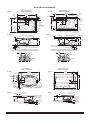
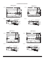
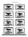
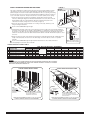
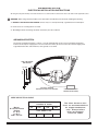
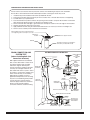
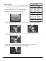
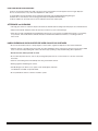
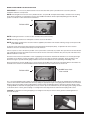
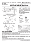
INSTALLATION GUIDE FOR
GREEN TEA™
5' x 36"
MODEL 3571
GREEN TEA™
5-1/2' x 36"
MODEL 3572
GREEN TEA™
6' x 36"
MODEL 3573
GREEN TEA™
5' x 42"
MODEL 3574
GREEN TEA™
6' x 42"
MODEL 3575
TOWN SQUARE®
5' x 42"
MODEL 2748
TOWN SQUARE®
6' x 42"
MODEL 2742
ELLISSE
OVAL
MODEL 2709
AIR MASSAGE SYSTEM
THANK YOU...
for selecting an American Standard bath. Your new bath is shipped to you after careful inspection. The Air
Massage System is completely assembled with air pump, motor, lights, and system piping. All you need to
finish the installation are your selected fittings and electrical connections for an Air Massage System.
To insure maximum performance and pleasure from this product, please follow the instructions and cautions.
FOR AFTER-SALES SERVICE CALL 1 (00) 44-10 WEEKDAYS.
© AS America, Inc. 00
All product names listed herein are trademarks
of AS America, Inc. unless otherwise noted.
754063-100 Rev. B
TABLE OF CONTENTS:
Cover................................................................................................Page 1
Table of Contents..............................................................................Page Safety Instructions Notice.................................................................Page 3
Roughing-in Reference.....................................................................Page 4 - 6
Installation and Framing Instructions................................................Page 7 - Supplied Drain Assembly and Installation Instructions.....................Page - 13
Post Installation Instructions.............................................................Page 14
Remote Blower Location Option.......................................................Page 15
Warranty...........................................................................................Page 16
754063-100 Rev. B
IMPORTANT SAFETY INSTRUCTIONS
READ AND FOLLOW ALL INSTRUCTIONS!
!
WARNING: Risk of personal injury. Do not permit children to use this bathtub without adult supervision.
!
WARNING: Risk of electric shock. Do not permit electrical appliances near any bathtub when bathtub contains water.
!
WARNING: Risk of hyperthermia and possible drowning. People using medications and/or having adverse medical
!
WARNING: Risk of personal injury. Do not overfill bathtub before entering. Entering tub when filled more than /3 can
history should consult a physician before using this product.
cause overflow and slippery conditions. Exercise caution when entering and exiting.
!
WARNING: No Food or Alcoholic Beverages. Use of your bathtub immediately after meals is not recommended. Avoid
alcohol consumption before or during bathing. Alcoholic beverages can cause drowsiness or hyperthermia resulting in loss of
consciousness or even drowning.
!
WARNING: Pregnancy. If you are or think you may be pregnant, consult your physician before using the bathtub.
Use this unit only for its intended use as described in this manual. Do not use any attachments not recommended by American
Standard.
The unit must be connected only to a supply circuit that is properly protected by a ground-fault circuit-interrupter (GFCI). Such a
GFCI should be provided by the installer and should be tested on a routine basis. To test the GFCI, push the test button. The
GFCI should interrupt power. Push the reset button. Power should be restored. If the GFCI fails to operate in this manner, the
GFCI is defective. If the GFCI interrupts power to the bathtub without the test button being pushed, a ground current is flowing,
indicating the possibility of an electric shock. Do not use this air bath. Disconnect the air bath and have the problem corrected by a
licensed electrician before using.
SAVE THESE INSTRUCTIONS
754063-100 Rev. B
ROUGHING-IN REFERENCES
TOWN SQUARE® 5' x 42"
MODEL 2748 AIR BATH
TOP VIEW
59-1/2"
(1511mm)
CONTROL
PANEL
INTEGRAL
FITTING DECK
2-1/2" X 14"
(64 X 356mm)
29-3/4"
(755mm)
14-1/2"
(368mm)
3"
(76mm)
10-1/4"
(260mm)
4"
(102mm)
5-1/4"
(133mm)
7-3/4" TYPICAL
(197mm)
INTEGRAL
FITTING DECK
2-1/4" X 14"
(57 X 356mm)
CONTROL
PANEL
3"
(76mm)
C/L OF
DRAIN
OUTLET
OUTLINE OF CUTOUT
58" X 40-1/8"
(1473 X 1019mm)
AIR
BLOWER
71-1/2"
(1816mm)
35-3/4"
(908mm)
13-1/4"
(337mm)
C/L OF
DRAIN
OUTLET
EDGE OF
FLOOR
CUTOUT
FLOOR CUTOUT
9" X 18"
(229 X 458mm)
41-5/8"
(1057mm)
TOWN SQUARE® 6' x 42"
MODEL 2742 AIR BATH
TOP VIEW
41-3/4"
(1060mm)
7-3/4” TYPICAL
(197mm)
3/4"
(19mm)
EDGE OF
FLOOR
CUTOUT
10-1/4”
(260mm)
26-3/4
(679mm)
FLOOR CUTOUT
9" X 19"
(229 X 459mm)
AIR BLOWER
20 AIR JETS
3/4"
(19mm)
PROVIDE ACCESS TO BLOWER FOR
SERVICE ON ALL INSTALLATIONS
END VIEW
OUTLINE OF SKID
RESISTANT SURFACE
END VIEW
AIR
BLOWER
C/L OF
OVERFLOW
2"
(51mm)
LEVELING STRINGER
(NOT FOR SUPPORT)
2"
(51mm)
1-1/2" N.P.T. THREADS
1-1/2" O.D. TAILPIECE
3/4"
(19mm)
INTEGRAL FEET WITH
ATTACHED BASEBOARD
INTEGRAL FEET WITH
ATTACHED BASEBOARD
FOR HAND
SPRAY
C/L
DRAIN
FITTINGS
DECK
FOR HAND
SPRAY
1-1/2
(38mm)
2-1/2
(64mm)
4-1/2
4-1/2
5
(114mm) (114mm) (127mm)
TOP VIEW
EDGE OF
FITTINGS
1-1/2
(38mm) DECK
1759 mm
(69-1/4")
240 mm
(9-7/16")
SEE FTTG.SPECS
FOR DIMENSION
1-1/2
(38mm)
60
(1524mm)
TOP VIEW
OUTLINE OF CUTOUT 58.5 x 34.5 (1486 x 876mm)
OUTLINE OF
CUTOUT
CONTROL
PANEL
14-3/4
(375mm)
11-1/2
(292mm)
36
(914mm)
BLOWER
AIR
BLOWER
FLOOR CUTOUT
229 X 459mm
(9" X 19")
978 mm
(38-1/2")
EDGE OF
FITTINGS
1-1/2
(38mm) DECK
2-1/2
(64mm)
4-1/2
4-1/2
5
(114mm) (114mm) (127mm)
GREEN TEA™ 5' x 36"
MODEL 3571 AIR BATH
7-3/4" TYPICAL
(197mm)
CL OF SUPPLIES
9
(229mm)
CL
CUTOUT IN FLOOR FOR DRAIN
489mm
(19-1/4")
76mm
(3")
C
L OF DRAIN
OUTLET
16 AIR JETS
PROVIDE ACCESS
TO BLOWER FOR
SERVICING ON ALL
INSTALLATIONS
PROVIDE ACCESS TO BLOWER FOR
SERVICE ON ALL INSTALLATIONS
END VIEW
CL TO OVERFLOW
86mm (3-3/8")
38mm
(1-1/2")
INTEGRAL FEET
WITH ATTACHED
BASEBOARD
495mm
(19-1/2")
1-1/2" N.P.T.M. THREADS
1-1/2" O.D. TAILPIECE
CL TO OVERFLOW
102mm (4")
51mm
(2")
533mm
(21")
754063-100 Rev. B
3"
(76mm)
5/8"
(16mm)
FOR SPOUT
& VALVES
ELLISSE OVAL
MODEL 2709 AIR BATH
11-1/4"
(286mm)
1-1/2" N.P.T. THREADS
1-1/2" O.D.TAILPIECE
35-3/4
(908mm)
TO END OF TUB
1-1/2
(38mm)
1-1/2
(38mm)
20"
(508mm)
HOLE DRILLING LOCATION FOR AMERICAN STANDARD "TOWN SQUARE"
DECK MOUNT BATH FILLER WITH PERSONAL SHOWER, MODEL #2555.901 ONLY
FITTINGS
DECK
FOR SPOUT
& VALVES
22"
(559mm)
ROUGH
FLOOR
C/L
DRAIN
C/L OF
OVERFLOW
3-1/4"
(83mm)
HOLE DRILLING LOCATION FOR AMERICAN STANDARD "TOWN SQUARE"
DECK MOUNT BATH FILLER WITH PERSONAL SHOWER, MODEL #2555.901 ONLY
29-3/4
(755mm)
TO END OF TUB
PROVIDE ACCESS
TO BLOWER FOR
SERVICE ON ALL
INSTALLATIONS
LEVELING STRINGER
(NOT FOR SUPPORT)
AIR BLOWER
21"
(533mm)
ROUGH
FLOOR
END VIEW
20 AIR JETS
OUTLINE OF CUTOUT
70" X 40-1/4" (1778 X 1022mm)
23"
(584mm)
5-3/4"
(146mm)
3-1/8"
(79mm)
OUTLINE OF SKID
RESISTANT SURFACE
20 AIR JETS
LEVELING STRINGER NOT
FOR SUPPORT
559mm
(22")
INTEGRAL FEET
WITH ATTACHED
BASEBOARD
ROUGH
FLOOR
508mm
(20")
ROUGH
FLOOR
35mm
(1-3/8")
CONTROL
PANEL
1-1/2" N.P.T.M. THREADS
1-1/2" O.D. TAILPIECE
98mm
(3-7/8")
35mm
(1-3/8")
98mm
(3-7/8")
ROUGHING-IN REFERENCES
GREEN TEA™ 5-1/2' x 36"
MODEL 3572 AIR BATH
GREEN TEA™ 6' x 36"
MODEL 3573 AIR BATH
66
(1676mm)
TOP VIEW
OUTLINE OF CUTOUT 64.5 x 34.5 (1638 x 876mm)
72
(1829mm)
TOP VIEW
14-3/4
(292mm)
11-1/2
(292mm)
14-3/4
(375mm)
36
(914mm)
9
(229mm)
36
(914mm)
BLOWER
BLOWER
9
(229mm)
CL
PROVIDE ACCESS TO BLOWER FOR
SERVICE ON ALL INSTALLATIONS
END VIEW
CL TO OVERFLOW
102mm (4")
51mm
(2")
CONTROL
PANEL
23 AIR JETS
END VIEW
CL TO OVERFLOW
102mm (4")
51mm
(2")
559mm
(22")
INTEGRAL FEET
WITH ATTACHED
BASEBOARD
ROUGH
FLOOR
508mm
(20")
35mm
(1-3/8")
LEVELING STRINGER NOT
FOR SUPPORT
559mm
(22")
INTEGRAL FEET
WITH ATTACHED
BASEBOARD
ROUGH
FLOOR
508mm
(20")
98mm
(3-7/8")
1-1/2" N.P.T.M. THREADS
1-1/2" O.D. TAILPIECE
GREEN TEA™ 5' x 42"
MODEL 3574 AIR BATH
35mm
(1-3/8")
98mm
(3-7/8")
GREEN TEA™ 6' x 42"
MODEL 3575 AIR BATH
60
(1524mm)
TOP VIEW
CONTROL
PANEL
22 AIR JETS
LEVELING STRINGER NOT
FOR SUPPORT
1-1/2" N.P.T.M. THREADS
1-1/2" O.D. TAILPIECE
CL
CUTOUT IN FLOOR
FOR DRAIN
CUTOUT IN FLOOR FOR DRAIN
PROVIDE ACCESS TO BLOWER FOR
SERVICE ON ALL INSTALLATIONS
11-1/2
(292mm)
OUTLINE OF CUTOUT 70.5 x 34.5 (1780 x 876mm)
OUTLINE OF CUTOUT 58.5 x 40.5 (1486 x 1029mm)
72
(1829mm)
14-3/4
(375mm)
11-1/2
(292mm)
TOP VIEW
14-3/4
(375mm)
11-1/2
(292mm)
OUTLINE OF CUTOUT 70.5 x 40.5 (1780 x 1029mm)
42
(1067mm)
42
(1067mm)
BLOWER
BLOWER
9
(229mm)
9
(229mm)
CL
CUTOUT IN FLOOR FOR DRAIN
CUTOUT IN FLOOR FOR DRAIN
PROVIDE ACCESS TO BLOWER FOR
SERVICE ON ALL INSTALLATIONS
CONTROL
PANEL
CL
PROVIDE ACCESS TO BLOWER FOR
SERVICE ON ALL INSTALLATIONS
23 AIR JETS
END VIEW
CONTROL
PANEL
27 AIR JETS
END VIEW
CL TO OVERFLOW
102mm (4")
51mm
(2")
559mm
(22")
1-1/2" N.P.T.M. THREADS
1-1/2" O.D. TAILPIECE
35mm
(1-3/8")
LEVELING STRINGER NOT
FOR SUPPORT
559mm
(22")
INTEGRAL FEET
WITH ATTACHED
BASEBOARD
ROUGH
FLOOR
508mm
(20")
CL TO OVERFLOW
102mm (4")
51mm
(2")
LEVELING STRINGER NOT
FOR SUPPORT
INTEGRAL FEET
WITH ATTACHED
BASEBOARD
ROUGH
FLOOR
508mm
(20")
1-1/2" N.P.T.M. THREADS
1-1/2" O.D. TAILPIECE
98mm
(3-7/8")
35mm
(1-3/8")
98mm
(3-7/8")
754063-100 Rev. B
ROUGHING-IN REFERENCES
TOWN SQUARE® 6' x 42"
MODEL 2742 AIR BATH
TOWN SQUARE® 5' x 42"
MODEL 2748 AIR BATH
GENERAL SPECIFICATIONS FOR 2748
AIR MASSAGE SYSTEM
GENERAL SPECIFICATIONS FOR 2742
AIR MASSAGE SYSTEM
INSTALLED SIZE
71-1/2 x 41-3/4 x 22 In. (1816 x 1060 x 559mm)
WEIGHT
115 Lbs. (52 Kg.)
WEIGHT w/WATER
690 Lbs. (313 Kg.)
GAL. TO OVERFLOW
69 Gal. (261 L)
BATHING WELL AT SUMP
41 x 21-1/2 In. (1041 x 546mm)
BATHING WELL AT RIM
62 x 31-1/2 In. (1574 x 800mm)
WATER DEPTH TO OVERFLOW
14-1/4 In. (362mm)
FLOOR LOADING
33 Lbs./Sq.Ft. (163 Kgs./Sq.m)
(PROJECTED AREA)
PTS.
27.8
CUBE (FT 3 )
55.7
INSTALLED SIZE
59-1/2 x 41-5/8 x 23 In. (1511 x 1057 x 584mm)
WEIGHT
110 Lbs. (50 Kg.)
WEIGHT w/WATER
611 Lbs. (278 Kg.)
GAL. TO OVERFLOW
60 Gal. (227 L)
BATHING WELL AT SUMP
34 x 24 In. (864 x 610mm)
BATHING WELL AT RIM
52 x 31 In. (1321 x 1321mm)
WATER DEPTH TO OVERFLOW
12-1/2 In. (318mm)
FLOOR LOADING
40 Lbs./Sq.Ft. (194 Kgs./Sq.m)
(PROJECTED AREA)
PTS.
27.8
CUBE (FT 3 )
45.4
ELECTRICAL SPECIFICATIONS
ELECTRICAL SPECIFICATIONS
BLOWER
BLOWER
1.0 HP, 10 AMPS ,120V.
GREEN TEA™ 5' x 36"
MODEL 3571 AIR BATH
ELLISSE OVAL
MODEL 2709 AIR BATH
GENERAL SPECIFICATIONS FOR 2709 AIR BATH
GENERAL SPECIFICATIONS FOR 3571
AIR BATH SYSTEM
INSTALLED SIZE
69-1/4 x 38-1/2 x 19-3/4 In.(1759 x 978 x 502mm)
WEIGHT
107 Lbs. (49 Kg.)
WEIGHT w/WATER
640 Lbs. (291 Kg.)
GAL. TO OVERFLOW
64 Gal. (243 L)
BATHING WELL AT SUMP
45 x 23 In. (1143 x 584mm)
BATHING WELL AT RIM
63 x 32 In. (1600 x 813mm)
WATER DEPTH TO OVERFLOW
13 In. (330mm)
FLOOR LOADING
35 Lbs./Sq.Ft. (166 Kgs./Sq.m)
(PROJECTED AREA)
PTS.
25.6
CUBE (FT 3 )
49.4
INSTALLED SIZE
WEIGHT
WEIGHT w/WATER
GAL. TO OVERFLOW
MIN. OPERATING GAL.
BATHING WELL AT SUMP
BATHING WELL AT RIM
WATER DEPTH TO OVERFLOW
FLOOR LOADING
(PROJECTED AREA)
PTS.
CUBE (FT 3 )
ELECTRICAL SPECIFICATIONS
BLOWER
BLOWER
GENERAL SPECIFICATIONS FOR 3572
AIR BATH SYSTEM
66 x 36 x 22 In. (1676 x 914 x 559mm)
100 Lbs. (45 Kg.)
592 Lbs. (269 Kg.)
59 Gal. (223 L.)
44 Gal. (167 L.)
19 x 49 In. (483mm x 1245mm)
54-1/2 x 27 In. (1384mm x 686mm)
14 In. (356mm)
36 Lbs./Sq. Ft. (175 Kgs/Sq. m.)
INSTALLED SIZE
WEIGHT
WEIGHT w/WATER
GAL. TO OVERFLOW
MIN. OPERATING GAL.
BATHING WELL AT SUMP
BATHING WELL AT RIM
WATER DEPTH TO OVERFLOW
FLOOR LOADING
(PROJECTED AREA)
PTS.
CUBE (FT 3 )
25.6
45.1
72 x 36 x 22 In. (1829 x 914 x 559mm)
115 Lbs. (52 Kg.)
665 Lbs. (302 Kg.)
66 Gal. (250 L.)
49 Gal. (185 L.)
19 x 55 In. (483mm x 1397mm)
60-1/2 x 27 In. (1537mm x 686mm)
14 In. (356mm)
37 Lbs./Sq. Ft. (175 Kgs/Sq. m.)
23.8
44.5
ELECTRICAL SPECIFICATIONS
BLOWER
1.0 HP, 10 AMPS, 120V.
1.0 HP, 10 AMPS, 120V.
GREEN TEA™ 6' x 42"
MODEL 3575 AIR BATH
GREEN TEA™ 5' x 42"
MODEL 3574 AIR BATH
GENERAL SPECIFICATIONS FOR 3574
AIR BATH SYSTEM
GENERAL SPECIFICATIONS FOR 3575
AIR BATH SYSTEM
INSTALLED SIZE
59-3/4 x 42 x 22 In. (1518 x 1060 x 559mm)
WEIGHT
115 Lbs. (52 Kg.)
656 Lbs. (298 Kg.)
WEIGHT w/WATER
65 Gal. (246 L.)
GAL. TO OVERFLOW
47 Gal. (178 L.)
MIN. OPERATING GAL.
24-1/2 x 42 In. (622mm x 1067mm)
BATHING WELL AT SUMP
48 x 33 In. (1219mm x 838mm)
BATHING WELL AT RIM
14 In. (356mm)
WATER DEPTH TO OVERFLOW
38 Lbs./Sq. Ft. (185 Kgs/Sq. m.)
FLOOR LOADING
(PROJECTED AREA)
27.8
PTS.
CUBE (FT 3 )
47.4
INSTALLED SIZE
WEIGHT
WEIGHT w/WATER
GAL. TO OVERFLOW
MIN. OPERATING GAL.
BATHING WELL AT SUMP
BATHING WELL AT RIM
WATER DEPTH TO OVERFLOW
FLOOR LOADING
(PROJECTED AREA)
PTS.
CUBE (FT 3 )
ELECTRICAL SPECIFICATIONS
754063-100 Rev. B
1.0 HP, 10 AMPS, 120V.
GENERAL SPECIFICATIONS FOR 3573
AIR BATH SYSTEM
ELECTRICAL SPECIFICATIONS
BLOWER
23.8
44.5
GREEN TEA™ 6' x 36"
MODEL 3573 AIR BATH
GREEN TEA™ 5-1/2' x 36"
MODEL 3572 AIR BATH
BLOWER
60 x 36 x 22 In. (1524 x 914 x 559mm)
86 Lbs. (39 Kg.)
519 Lbs. (235 Kg.)
52 Gal. (197 L.)
38 Gal. (144 L.)
19 x 43 In. (483mm x 1092mm)
48-1/2 x 27 In. (1232mm x 686mm)
14 In. (356mm)
35 Lbs./Sq. Ft. (169 Kgs/Sq. m.)
ELECTRICAL SPECIFICATIONS
1.0 HP, 10 AMPS, 120V.
INSTALLED SIZE
WEIGHT
WEIGHT w/WATER
GAL. TO OVERFLOW
MIN. OPERATING GAL.
BATHING WELL AT SUMP
BATHING WELL AT RIM
WATER DEPTH TO OVERFLOW
FLOOR LOADING
(PROJECTED AREA)
PTS.
CUBE (FT 3 )
1.0 HP, 10 AMPS ,120V.
72 x 42 x 22 In. (1829 x 1067 x 559mm)
127 Lbs. (58 Kg.)
785 Lbs. (356 Kg.)
79 Gal. (299 L.)
58 Gal. (219 L.)
22-1/2 x 54 In. (572mm x 1372mm)
60 x 33 In. (1524mm x 838mm)
14 In. (356mm)
37 Lbs./Sq. Ft. (185 Kgs/Sq. m.)
25.6
49.4
ELECTRICAL SPECIFICATIONS
1.0 HP, 10 AMPS, 120V.
BLOWER
1.0 HP, 10 AMPS, 120V.
INSTALLATION AND FRAMING INSTRUCTIONS:
FIGURE 1
TYPICAL
INSTALLATION
The variety of installations possible for this air massage system may require framing procedures
other than those shown. Locate studs as required. Ensure roughing-in dimensions are proper,
plumb and square. Provisions must be made in all installations for an access opening for servicing
the air blower and controls. It is strongly recommended that an additional opening be provided for
access to the drain components. The apron should not be used as the primary access opening.
1. Position the air massage system into the installation opening and level the deck in both
directions, shimming the integral feet with attached baseboard as necessary. Refer to the Air
Bath Installation Table for nominal installation dimensions. Mark the final position of the
underside of the deck by tracing a line on to the studs (see Figure 1).
D
. Remove the air massage system and attach a 1 x 4 stringer to the studs, with the top of the
stringer touching the traced line.
!
The rim of the bath must not support weight.
3. Install supplied cable drain components to the air massage system according to the enclosed drain installation
instructions. Before replacing your air bath for final installation, be certain that an opening has been provided in
the sub-floor for the drain. See the roughing-in drawing for suggested opening size (shadowed) and location
dimensions. The drain/overflow of the bath extends below the bottom of the bath. Note that this requires a cutout
in the floor.
TILE
WALLBOARD
The rim of the bath must not support weight. Any finish material such as tile or wall board must be
self-supporting if it contacts the deck of the bath.
BATH
ADHESIVE
4. Replace air massage system and re-shim the integral support feet with attached baseboard, shimming the entire
length of the baseboard as needed. Secure the shims using construction adhesive, silicone or equivalent
materials.
!
SEALANT
TILE
BEAD
STRIP
LEVELING STRINGER
1 x 4 (not for support)
NOTE: Tile bead kit not included
and must be purchased separately.
DIM.
AIR BATH INSTALLATION TABLE
A
B
C
D
E
F
DESCRIPTION
Nominal tub length recess opening
Nominal tub apron support opening
Nominal tub width recess opening
Nominal tub height opening
Nominal tub length cutout
Nominal tub width cutout
2748
5-3/4" 151mm
3-3/4" 1511mm
41-3/4" 1060mm
1" 533mm
5" 1473mm
40-1/" 101mm
AIR BATH MODEL NUMBER
3571
3572
3573
2709 **
2742
71-3/4" 13mm
60-1/4" 1530mm 66-1/4" 163mm 7-1/4" 135mm
3-3/4" 1511mm
35" mm 35" mm 35" mm
41-3/4" 1060mm
36" 14mm 36" 14mm 36" 14mm
0" 50mm 1-1/" 45mm 1" 43mm 1" 43mm 1" 43mm
70" 177mm 67" 170mm 5-1/" 146mm 64-1/" 163mm 70-1/" 171mm
40-1/4" 10mm 36-1/" 7mm 34-1/" 76mm 34-1/" 76mm 34-1/" 76mm
3574
3575
60" 154mm 7-1/4" 135mm
40-3/4" 1035mm 41" 1041mm
41-3/4" 1060mm 4" 1067mm
1" 43mm
1" 43mm
5-1/4" 140mm 70-1/" 171mm
40-1/4" 10mm 40-1/" 10mm
** USE CUTOUT TEMPLATE PROVIDED FOR 70 MODEL
NOTICE:
DO NOT BUILD THE SURROUNDING STRUCTURE BEFORE RECEIVING YOUR AIR BATH.
STRUCTURE MEASUREMENTS SHOULD BE VERIFIED AGAINST THE ACTUAL AIR BATH
RECEIVED TO ENSURE PROPER FIT.
TYPICAL PIER TYPE INSTALLATION
TYPICAL RECESS INSTALLATION
AS DESIRED
F
CUTOUT
E
CUTOUT
D
D
B
1
(305 mm)
C
A
NOTE:
FRONT EDGE
OF BATH MUST
BE SUPPORTED
BY STUD WALL OR
AMERICAN STANDARD
APRON KIT
1
(305 mm)
AS DESIRED
LEVELING
STRINGERS
MOUNTING
SURFACE
WATERPROOF
SEALANT
4
(610 mm)
ACCESS PANEL MUST BE LOCATED
ON THE SAME SIDE AS THE BLOWER.
ALLOW OPEN FRAMING ON
BLOWER END FOR SERVICE.
BATH
UNLESS AN ACCESS OPENING OF AT LEAST 12" X 24" (305 X 610mm)
IS PROVIDED, WARRANTY SERVICE WILL NOT BE PERFORMED.
4
(610 mm)
ACCESS PANEL MUST BE LOCATED
ON THE SAME SIDE AS THE MOTOR.
ALLOW OPEN FRAMING ON PUMP/MOTOR
END FOR SERVICE.
UNLESS AN ACCESS OPENING OF AT LEAST 12" X 24" (305 X 610mm)
IS PROVIDED, WARRANTY SERVICE WILL NOT BE PERFORMED.
754063-100 Rev. B
AIR MASSAGE SYSTEM
ELECTRICAL INSTALLATION INSTRUCTIONS
All wiring must be performed by a licensed electrician in accordance with the national electrical code and all other applicable codes.
!
WARNING: When using electrical products, basic precautions should always be observed, including the following:
1. DANGER: RISK OF ELECTRIC SHOCK! Connect only to a circuit protected by a ground-fault circuit interrupter.
2. Permit access for servicing blower as noted.
3. All building materials and wiring should be routed away from the air blower.
AIR MASSAGE SYSTEM:
The air bath should be installed on a 10 vac, 15 or 0 amp dedicated circuit. The circuit should be hard-wired
from the electrical power supply panel. The circuit must be a three (3) wire circuit from the electrical supply panel.
A grounded neutral wire and a third wire, earth ground, are essential.
USE 15 OR 20 AMP
GFCI OUTLET
BLACK
WHITE
120 VAC
GND.
AIR BLOWER
ELECTRICAL DIAGRAM
READ AND FOLLOW ALL INSTRUCTIONS
CHROMATHERAPY LIGHT
CONTROL BOX (OPTIONAL)
WI R E S E L E C T I O N G U I D E
Ma x i m u m d i s t a n c e f r o m
fusebox to motor
Motor
Hi Performance
Rating
2.1 H.P.,
1.4 H.P.,
a n d 1 . 2 5 H. P .
754063-100 Rev. B
50'
100'
150'
200'
115V Power Line
12
10
8
8
T h e s i z e s s h o w n o n this
c h a r t a r e r e c o m m e n dations
f o r c o p p e r c o n d u ctors
o n l y . A l w a y s f o l low
l o c a l a n d n a t i o nal
electrical codes
UNDER DECK MOUNTING INSTRUCTIONS
Please note that care must be taken to protect the surface of the tub during all aspects of the installation.
Do not drill or cut the bath deck with the tub directly beneath it as damage to the tub may result.
1.
.
3.
4.
5.
6.
7.
.
Install the tub per the installation instructions provided with the unit.
Prepare the bath deck support structure per the local codes. Note - the bath deck must be self supporting.
Cut bath deck to your specifications.
Place the bath deck in position and trace the opening on the tub with a soft pencil. Do not drill or cut the bath
deck with the tub directly beneath it as damage to the tub may result.
Remove the bath deck and apply a generous bead of waterproof sealant on the outer edge of the traced line.
Replace the bath deck and secure it into place.
Apply additional sealant along the tub and bath deck interface as necessary to ensure a watertight seal.
Remove excess sealant per the manufacturer's instructions.
Finished bath deck surface material must be
self-supporting and secured per local codes
Waterproof
Sealant
Bath deck support material
Bathtub
Tub support structure per installation
instructions provided with the tub
DRAIN CONNECTION AND
SYSTEM TEST
(before installing bath into
framed out structure)
With supplied cable drain assembled to
bath, connect drain outlet to waste line in
accordance with the drain assembly
instructions. Tighten all drain joints
securely. Check the couplings and make
sure they are hand-tight. Clean the air
bath and fill with water to a point " below
the overflow. Recheck the couplings and
make certain that they are not leaking.
(Although the couplings are factory
tightened and inspected, some loosening
may have occurred during transit.) Make
sure the air bath is connected to the
electrical supply and turn the air bath on.
Check for leaks around all piping
connections while the air bath is running.
AIR BATH DRAIN ILLUSTRATION
DRAIN STOPPER
WITH
ADJUSTABLE
BOLT
METAL STRAINER
BOLT
METAL
STRAINER
OVERFLOW
ASSEMBLY
CLOSE
FLAT RUBBER
GASKET
OPEN
DRAIN WASTE
FLANGE
PLASTIC DRAIN BASE
WEDGE
GASKET
VERTICAL
DRAIN PIPE
OVERFLOW
ESCUTCHEON
OVERFLOW
ASSEMBLY
SET
SCREW
DRAIN ACTUATOR SHAFT
OVERFLOW
RETAINER
OVERFLOW NUT WITH O-RING
AIR BATH NUT
WITH WASHER
AND GASKET
0˚ ELBOW
HORIZONTAL
DRAIN PIPE
PLASTIC
DRAIN BASE
754063-100 Rev. B
DRAIN CONNECTION
PIPE CHART
1. Remove and identify all drain components as defined in air bath drain illustration.
MODEL VERTICAL HORIZONTAL
PIPE
PIPE
2. Find 1" schedule 40 PVC pipe, see pipe chart, HORIZONTAL DRAIN PIPE.
Mark as "horizontal pipe", drain to elbow section.
74
10.50"
6.50"
3. Find 1" schedule 40 PVC pipe, see pipe chart, VERTICAL DRAIN PIPE.
Mark as "vertical pipe", drain to elbow section.
74
1.00"
6.50"
4. Install drain from below unit through opening as shown in photo A.
70
11.00"
4.75"
3571
1.75"
5.75"
357
1.50"
6.00"
3573
1.75"
5.75"
3574
1.5"
5.75"
3575
1.50"
5.75"
A.
5. Apply 3 or 4 pea sized dabs of 100% silicone sealant to bottom waste drain flange and press flat rubber gasket into place
as shown in photos B and C.
B.
C.
6. Apply 1/" continuous bead of 100% silicone sealant to flat rubber gasket as shown in photo D. Set aside and be sure not to
disturb silicone bead.
D.
7. Apply 1/" continuous bead of 100% silicone sealant to back side to metal strainer as shown in photo E. Press
Strainer retaining bolt into metal strainer and insert into drain hole of acrylic bath.
E.
754063-100 Rev. B
10
DRAIN CONNECTION continued...
8. Have assistant take drain assembly from step 6 and place over back surface of drain hole to engage the metal strainer bolt.
Secure plastic drain base to metal strainer in drain opening using nut driver shaft. DO NOT OVER TIGHTEN! Carefully
remove excess silicone from acrylic surface as directed by silicone sealant directions.
9. From unit back side, overflow nut should be in alignment with overflow opening, as shown in photo F.
F.
Overflow nut
O-ring
10. Slide air bath fitting nut, washer and gasket onto air bath fitting as shown in photos G and H.
G.
H.
Air bath
fitting
11. Assemble air bath fitting to plastic drain base as shown in photos I, J, K and L. Hand tighten nut to create watertight joint.
I.
J.
K.
L.
11
754063-100 Rev. B
DRAIN CONNECTION continued...
12. Apply PVC cement to Horizontal Drain Pipe PVC and assemble to 0 degree elbow.
13. Dry fit Vertical Drain Pipe PVC into overflow assembly, then insert into elbow, WITHOUT PVC GLUE to align drain and
overflow to bath. Mark overflow female coupling as shown in photo M.
M.
14. Test fit and trim pipe as required to get overflow drain into center of overflow hole BEFORE GLUING vertical pipe into
0 degree elbow, as shown in photos N-1 and N-2.
N-1.
N-2.
15. Apply PVC cement to Vertical Drain Pipe sub-assembly and assemble per re-aligned marks from step 13.
16. Disassemble overflow wedge gasket and chrome overflow retainer as shown in photo O.
O.
17. Place overflow wedge gasket onto plastic overflow pipe flange with round raised rib surface contacting flange
as shown in photo P.
P.
754063-100 Rev. B
12
DRAIN CONNECTION continued...
18. Tighten chrome overflow retainer onto drain overflow assembly pipe per photo Q below.
19. Align flat on drain actuator shaft with corresponding flat in chrome metal overflow escutcheon and tighten set screw to fix
overflow escutcheon in place per photos R and S.
Q.
R.
S.
20. Rotate left and right lightly to feel stops in drain cable control. This opens and closes drain.
21. Place drain stopper into drain waste hole as shown in photo T.
T.
22. The drain stopper should prevent water from draining out of tub when the escutcheon is in the fully counterclockwise
position as shown in photo U. Adjust the drainstopper bolt to obtain the best water seal in the tub.
U.
23. Rotate Drain Escutcheon to clockwise stop. This should open drain, between 1/" and 1/4", to allow water to exit bath.
If not adjust metal bolt in drain stopper to allow draining function, but not so high that drain will not seal when closed to
hold water during use. See photo V.
V.
13
754063-100 Rev. B
POST INSTALLATION CLEAN-UP
Remove all construction debris from bath. Tile grout can be removed with a wooden popsicle stick or tongue depressor.
Do not use wire brushes or any other metal implement on bath surface.
Post installation clean-up generally can be completed using warm water and liquid dishwashing detergent.
Stubborn dirt or stains may be removed using granular Spic and Span® mixed with water.
Painter's naphtha can be used to remove excess adhesives and/or wet oil-base paint.
AFTERCARE and CLEANING
• The high gloss surface is resistant to impact and chemicals and will retain its lasting luster with proper care and maintenance.
• Always fill the tub with temperate water. Excessively hot water may cause surface damage
• Clean after use with a mild liquid household detergent cleaner. Do not use Lestoil, Lysol Disinfectant (spray or concentrate),
or Lysol Basin, Tub and Tile Cleaner, Windex, Mr. Clean, Dow Disinfectant Bathroom Cleaner, or cleaning products in
aerosol cans.
HARSH CHEMICALS SHOULD NEVER BE USED ON ACRYLIC SURFACES.
• Do not use wire brushes, knives or sharp objects to remove stains, cigarette tar deposits,or other surface blemishes.
• Abrasive cleaners or powders must not be used, since they will dull the surface. If the glossy surface looses its sheen, dulled
areas can be restored by rubbing with a white "automotive type" polishing compound and waxing with a "liquid wax."
• Do not wax areas where you walk or stand.
• Do not allow nail polish remover, acetone, dry cleaning fluid, paint remover or other solvents to come into contact with
the surface.
• Clean the surrounding surface immediately after using caustic drain cleaners.
• Burning cigarettes will damage the surface.
• Should damage to the fixture occur, repairs can be made quickly and easily.
Your distributor or builder can provide details.
• Do not permit drain cleaner to enter the circulation system.
754063-100 Rev. B
14
REMOTE BLOWER LOCATION OPTION
IMPORTANT! It is not necessary that the blower motor be relocated. This option is provided for the case that a particular
installation makes this effort practical.
NOTE: Relocating blower motor from factory installed location, see photo W, will require disassembly of air blower from mounting
board. Keep all hardware for reattachment at new location. Additional hardware will be required depending upon final desired
position of air blower. Follow all instructions listed below.
W.
TYPICAL VIEW
NOTE: Installing the blower in a remote location will reduce the system efficiency.
NOTE: Relocating a blower motor still requires a service access for the blower.
NOTE: All materials needed for the relocation must be supplied by the installer. This includes ordering a longer control panel cable
(P/N 75405-0071A).
A separate circuit, which must be protected by the Ground Fault Circuit Interrupter (GFCI), is required in the remote location.
Electrical connections should be performed by a licensed electrician.
Choose a space as close to the bath as possible so the system works as efficiently as possible. The space must be at least 30 cubic
feet and the blower must be mounted at least inches above the floor and inches minimum away from any wall. The blower must
NOT be installed in an attic area.
The blower motor must be located within 1 feet of rigid piping from the bath air manifold. This limitation is for the total pipe length
and applies to any direction changes and elbows. There can be no more than six changes of direction. There should be as few
direction changes as possible and the piping installation must meet all requirements of local plumbing and building codes.
Disconnect the blower from the flexible hose as shown in photo X. Do NOT remove the check valve manifold that is mounted to the
underside of the air bath. The manifold MUST remain mounted above the tub overflow level as shown in X.
X.
Do NOT move check
valve manifold
TYPICAL VIEW
Use 1 1/” PVC rigid piping and couplings to extend the blower motor location as shown in photos Y and Z. Detach the flexible hose
section from the blower end and extend the air line by adding the appropriate length of PVC piping. Mount the blower in a horizontal
direction using the mounting screws provided with the air bath system. Do NOT glue piping to either the manifold or blower. These
couplings MUST be attached to the piping with screws as shown in photos Y and Z. Glue only the PVC piping and couplings needed
to extend the air line. Let the glued couplings set overnight before attaching the blower and manifold couplings with screws.
CAUTION: It is imperative to let the glued piping set overnight as there may be fumes from the glue that could be ignited if not
allowed to dissipate.
Y.
Z.
15
754063-100 Rev. B
AS America, Inc. Limited Lifetime Warranty for Premium Acrylic Air Baths
AS America, Inc. (”American Standard”) warrants to the original consumer purchaser that it will, at its option,
repair or replace this whirlpool or any of its parts that are found by American Standard, in its sole judgment,
to be defective under normal residential use and maintenance so long as it is owned by the original
consumer purchaser.
This warranty shall only become effective upon receipt by American Standard of a completely filled out
Warranty Registration Card evidencing proof of purchase.
This limited warranty does not apply to commercial installations. The warranty for commercial installations is
three (3) years.
THIS WARRANTY SHALL BE VOID IF THE ACCESS PANEL TO THE WHIRLPOOL IS COVERED IN ANY
MANNER CONTRARY TO THE INSTALLATION INSTRUCTIONS. In no event will American Standard be
liable for the cost of repair or replacement of any installation materials including but not limited to tiles,
marble etc.
This limited warranty DOES NOT COVER the following:
1. Defects or damages arising from shipping, installation, alterations, accidents, abuse, misuse, lack of
proper maintenance and cleaning as directed in the owner’s manual and use of other than genuine
American Standard replacement parts, in all cases whether caused by a plumbing contractor, service
company, the owner or any other person.
. Deterioration through normal wear and tear and the expense of normal maintenance.
3. Commercial application.
4. Options and accessories. American Standard’s limited warranty on these items is one year for parts only
and excludes labor. This one year limited warranty covers accessories manufactured by American
Standard (e.g. aprons, drains, grab bars, heaters, trim kits) against defects of material or workmanship.
Warranty coverage begins on the date the accessory was originally purchased by the owner.
5. Postage or shipping costs for returning products for repairs or replacement under this limited warranty and
labor or other costs incurred in connection with product removal or installation under this limited warranty.
6. ANY LIABILITY FOR CONSEQUENTIAL OR INCIDENTAL DAMAGES, ALL OF WHICH ARE HEREBY
EXPRESSLY DISCLAIMED, OR THE EXTENSION BEYOND THE DURATION OF THIS LIMITED
WARRANTY OF ANY IMPLIED WARRANTIES, INCLUDING THOSE OF MERCHANTABILITY OR
FITNESS FOR AN INTENDED PURPOSE. (Some jurisdictions do not allow limitations on how long an
implied warranty lasts, or the exclusion or limitation of incidental or consequential damages, so these
limitations and exclusions may not apply to you.)
7. Responsibility for compliance with local code requirements. (Since local code requirements vary greatly
distributors, retailers, dealers, installation contractors and users of plumbing products should determine
whether there are any code restrictions on the installation or use of a specific product.)
This warranty gives you specific legal rights. You may have other legal rights that vary from state to state.
For service under this warranty, you should contact the following:
By Mail: American Standard Inc.
P.O. Box 65
West Caldwell, N.J. 07007
Attention: Customer Care Center
754063-100 Rev. B
16
By Telephone:
1-800-442-1902