1
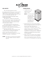
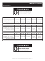
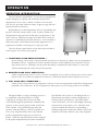
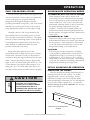
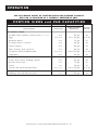
®
P RO C E S S I N G F R E EZ E R \ C H I LLE R \ R E F R I G E RAT I O N SYST E M
Model:
QC-3
QC-20
QC-40
QC-50
QC-50 REMOTE
QC-100
QC-100 REMOTE
QC-100
QC-40
• I N STALLATION
• OPERATION
QC-20
• MAI NTENANCE
W164 N9221 Water Street • P.O. Box 450 • Menomonee Falls, Wisconsin 53052-0450 USA
PHONE: 262.251.3800 • 800.558.8744 USA / CANADA
FAX: 262.251.7067 • 800.329.8744 U . S . A .
www.alto-shaam.com
PRINTED IN U.S.A.
ONLY
MN-28606 • 07/08
®
DELIVERY
U N PA C K I N G
This Alto-Shaam appliance has been
thoroughly tested and inspected to insure only the
highest quality unit is provided. Upon receipt,
check for any possible shipping damage and report
it at once to the delivering carrier. See
Transportation Damage and Claims section
located in this manual.
This appliance, complete with unattached
items and accessories, may have been delivered in
one or more packages. Check to ensure that all
standard items and options have been received
with each model as ordered.
Save all the information and instructions
packed with the appliance. Complete and return
the warranty card to the factory as soon as
possible to assure prompt service in the event of a
warranty parts and labor claim.
This manual must be read and understood by
all people using or installing the equipment
model. Contact the Alto-Shaam service
department if you have any questions concerning
installation, operation, or maintenance.
NOTE: All claims for warranty must include the
full model number and serial number of
the unit.
1. Carefully remove the
appliance from the
carton or crate.
NOTE: Do not discard the
carton and other
packaging material
until you have
inspected the unit
for hidden damage
and tested it for
proper operation.
®
®
2. Read all instructions in this manual carefully
before initiating the installation of this appliance.
DO NOT DISCARD THIS MANUAL.
This manual is considered to be part of the
appliance and is to be provided to the owner or
manager of the business or to the person
responsible for training operators. Additional
manuals are available from the Alto-Shaam
service department.
3. Remove all protective plastic film, packaging
materials, and accessories from the appliance
before connecting electrical power. Store any
accessories in a convenient place for future use.
Q U I C K C H I L L E R • I N S TA L L AT I O N / O P E R AT I O N / S E R V I C E M A N U A L • 1 .
SAFETY PROCEDURES
AND PRECAUTIONS
Knowledge of proper procedures is essential to the
safe operation of electrically and/or gas energized
equipment. In accordance with generally accepted
product safety labeling guidelines for potential
hazards, the following signal words and symbols
may be used throughout this manual.
DANGER
Used to indicate the presence of a
hazard that WILL cause severe
personal injury, death, or substantial
property damage if the warning
included with this symbol is ignored.
WA R N I N G
Used to indicate the presence of a
hazard that CAN cause personal injury,
possible death, or major property
damage if the warning included with
this symbol is ignored.
1. This appliance is intended to cook, hold or
process foods for the purpose of human
consumption. No other use for this appliance is
authorized or recommended.
2. This appliance is intended for use in commercial
establishments where all operators are familiar
with the purpose, limitations, and associated
hazards of this appliance. Operating
instructions and warnings must be read and
understood by all operators and users.
3. Any troubleshooting guides, component views,
and parts lists included in this manual are for
general reference only and are intended for use
by qualified technical personnel.
4. This manual should be considered a permanent
part of this appliance. This manual and all
supplied instructions, diagrams, schematics,
parts lists, notices, and labels must remain with
the appliance if the item is sold or moved to
another location.
CAUTION
Used to indicate the presence of a
hazard that can or will cause minor or
moderate personal injury or property
damage if the warning included with
this symbol is ignored.
CAUTION
Used to indicate the presence of a hazard that can
or will cause minor personal injury, property
damage, or a potential unsafe practice if the
warning included with this symbol is ignored.
N O T E : Used to notify personnel of
installation, operation, or
maintenance information that is
important but not hazard related.
Q U I C K C H I L L E R • I N S TA L L AT I O N / O P E R AT I O N / S E R V I C E M A N U A L • 2 .
I N S TA L L AT I O N
S I T E I N S TA L L AT I O N
I N S TA L L AT I O N
SITE SELECTION
Prior to moving the Quickchiller to the installation
site, check the dimensions of doors, passageways,
and ceiling heights in the areas through which the
cabinet must be moved. Also check the turning
radius if the cabinet must be moved around an
existing structure. The use of a fork lift or pallet
lift truck is required for moving and leveling most
Quickchiller models.
Position the Quickchiller to allow sufficient air
ventilation through the condensing unit(s). The
rear of unit should be no closer than 6" (152mm)
to any wall or structure.
Avoid installing the chiller immediately
adjacent to fryers, charbroilers, or any other
equipment producing grease laden air; heat
producing equipment such as ovens and
ranges; and steam discharging equipment
such as steamer ovens and kettles. Do not
locate the Quickchiller in direct sunlight.
NOTE: In certain instances, it may be
necessary to remove doors and door
hardware to negotiate tight spaces.
®
Allow sufficient front clearance for
serviceability and for easy maneuvering of
food trolleys in and out of the cabinet.
CLEARANCE REQUIREMENTS
CAUTION
TO PREVENT PERSONAL INJURY,
USE CAUTION WHEN MOVING OR
LEVELING THIS APPLIANCE.
5-YEAR LIMITED
WARRANTY ON
SELF-CONTAINED
COMPRESSOR
Effective from date of shipment.
( EXCLUDES LABOR )
BACK: 6" (152mm)
TOP: 6" (152mm)
SIDES: 4" (102mm) minimum at both sides.
18" (457mm)
MINIMUM CLEARANCE
FROM HEAT PRODUCING EQUIPMENT.
Unit must NOT be tipped on its side
at any time.
I N S TA L L AT I O N R E Q U I R E M E N T S
Tipping will cause damage to the unit
and void the warranty.
One (1) Floor Drain: 1/2" (12,7mm) diameter
Unit must be installed level. Unit must not be
installed in any area where it may be affected by
steam, grease, dripping water, high temperatures,
or any other severely adverse conditions.
Q U I C K C H I L L E R • I N S TA L L AT I O N / O P E R AT I O N / S E R V I C E M A N U A L • 3 .
I N S TA L L AT I O N
S I T E I N S TA L L AT I O N
DOOR SEAL:
Check the door gasket to make certain it is sealing
properly and that the gasket provides an even and
positive seal around the entire door frame.
I N S TA L L AT I O N R E Q U I R E M E N T S
The model QC-3 is a counter mounted unit and
must be sealed to the counter with a NSF listed
silicone sealant.
For all other
models, install
the appliance
on a smooth and level floor
surface. Use the adjustable cabinet legs to level
the Quickchiller.
CAUTION
TO PREVENT PERSONAL INJURY,
Adjust from front-to-back and from side-to-side
with the use of a spirit level to evenly distribute
the cabinet weight and avoid pulling the cabinet
alignment out of square.
USE CAUTION WHEN MOVING OR
LEVELING THIS APPLIANCE.
After leveling the cabinet of cart equipped models,
check the height relationship of the roll-in cart to
the cabinet. Adjust the Quickchiller height as
needed to accommodate the cart and to securely
close the Quickchiller door(s).
MODEL
DIMENSIONS:
HxW
X
D ( EST.)
WEIGHT ( EST.)
EXTERIOR
CRATED
NET
SHIP
QC-3
34" x 28" x 29-3/4"
(864 x 711 x 756mm)
36" X 36" X 42"
(914 x 914 x 1067mm)
350 lb
(159 kg)
382 lb
(173 kg)
QC-20
42-1/2" x 52-1/2" x 38"
(1079 x 1334 x 965mm)
60" x 40" x 42"
(1524 x 1016 x 1067mm)
442 lb
(200 kg)
600
(272 kg)
70-1/4" x 38-1/2" x 39-7/8"
80" x 42" x 46"
(1784 x 978 x 1013mm)
(1067 x 1168 x 2032mm)
676 lb
(307 kg)
950 lb
(431 kg)
QC-40
QC-50
76-1/2" x 51" x 41-1/8"
(1943 x 1295 x 1045mm)
79-1/2" x 55-1/4" x 48"
(2019 x 1403 x 1219mm)
590 lb
(268 kg)
900 lb
(408 kg)
QC-50
Remote
65-1/2" x 51" x 41-1/8"
(1664 x 1295 x 1045mm)
70-1/4" x 55-1/4" x 48"
(1784 x 1403 x 1219mm)
557 lb
(253 kg)
862 lb
(391 kg)
QC-100
95" x 51" x 41-1/8"
(2413 x 1295 x 1045mm)
98" x 55-1/4" x 48"
(2489 x 1403 x 1219mm)
1,152 lb
(523 kg)
1450 lb
(658 kg)
QC-100
Remote
83-3/4" x 51" x 41-1/8"
(2127 x 1295 x 1045mm)
88-1/2" x 55-1/4" x 48"
(2248 x 1403 x 1219mm)
902 lb
(409 kg)
1200 lb
(544 kg)
Q U I C K C H I L L E R • I N S TA L L AT I O N / O P E R AT I O N / S E R V I C E M A N U A L • 4 .
I N S TA L L AT I O N
S I T E I N S TA L L AT I O N
WAT E R D R A I N A G E
DRAINAGE:
QC-3
QC-20
QC-40
EVAPORATOR PANS: NO INSTALLATION REQUIRED
QC-50
QC-100
ONE (1) FLOOR DRAIN:
1/ 2" (12,7mm) DIAMETER
A 1/2" I.D. (12,7mm) PVC pipe is furnished with
each QC-50 and QC-100 model. Use PVC glue to
attach the pipe into the drain opening at the rear of
the unit. Insert the PVC pipe into the drain opening
with a 1/4" (6mm) clockwise turn. Connect the PVC
pipe to discharge through an indirect waste pipe into
an open-site drain by means of a 2" (51mm) air gap.
Connection must be within 10' (3m) of the unit.
NOTE: In the U.S.A., this equipment is to be
installed to comply with the Basic Plumbing
Code of the Building Officials and Code
Administrators International, Inc. [BOCA],
and the Food Service Sanitation Manual of
the Food & Drug Administration [FDA].
Q U I C K C H I L L E R • I N S TA L L AT I O N / O P E R AT I O N / S E R V I C E M A N U A L • 5 .
DRAIN OPENING
AT REAR
I N S TA L L AT I O N
ELECTRICAL
DANGER
ELECTRICAL CONNECTIONS MUST
BE MADE BY A QUALIFIED SERVICE
TECHNICIAN IN ACCORDANCE WITH
APPLICABLE ELECTRICAL CODES.
This appliance must be branch circuit protected
with proper ampacities, in accordance with the
wiring diagram. The Quickchiller must be
properly grounded in accordance with the
National Electrical Code and applicable local
codes. Wire size for the main incoming power to
the unit must match the minimum size listed in
the specifications applicable to the specific
Quickchiller model. For supply connections,
locate the wire size listed in this manual.
Before operating the chiller, check all cable
connections in the electrical connection area
for tightness since connections can loosen
during transport.
N O T E : After electrical connections have been
completed, operate the appliance in
any chilling mode for a period of 15
minutes and recheck the main power
connections at the terminal block to
make certain they remain tight.
DANGER
To avoid electrical shock, this
appliance MUST be adequately
grounded in accordance with local
electrical codes or, in the absence of
local codes, with the current edition
of the National Electrical Code
ANSI/NFPA No. 70. In Canada, all
electrical connections are to be
made in according with CSA C22.1,
Canadian Electrical Code Part 1 or
local codes.
Q U I C K C H I L L E R • I N S TA L L AT I O N / O P E R AT I O N / S E R V I C E M A N U A L • 6 .
I N S TA L L AT I O N
ELECTRICAL
DANGER
ELECTRICAL CONNECTIONS MUST
BE MADE BY A QUALIFIED SERVICE
TECHNICIAN IN ACCORDANCE WITH
APPLICABLE ELECTRICAL CODES.
VOLTAGE
PHASE
CYCLE / HZ
QC-3
QC-20
QC-40
QC-50
QC-100
30 amps
40 amps
60 amps
S E L F - C O N TA I N E D
208-240VAC 1 ph 50/60 Hz
R ECOMMENDED
CIRCUIT AMPERAGE :
R ECOMMENDED
WIRE SIZE :
20 amps
12/2 w.g.
20 amps
12/2 w.g.
10/2 w.g.
8/2 w.g.
6/2 w.g.
NO CORD AND PLUG
VOLTAGE
PHASE
CYCLE / HZ
QC-3
QC-20
QC-40
QC-50
QC-100
NOT AVAILABLE
NOT AVAILABLE
NOT AVAILABLE
20 amps
40 amps
S E L F - C O N TA I N E D
208-240VAC 3 ph 50/60 Hz
R ECOMMENDED
CIRCUIT AMPERAGE :
R ECOMMENDED
WIRE SIZE :
12/3 w.g.
8/3 w.g.
NO CORD AND PLUG
VOLTAGE
PHASE
CYCLE / HZ
QC-3
QC-20
QC-40
QC-50
QC-100
NOT AVAILABLE
NOT AVAILABLE
NOT AVAILABLE
20 amps
30 amps
REMOTE COMPRESSOR
(Cabinet Only)
208-240VAC 1 ph 50/60 Hz
R ECOMMENDED
CIRCUIT AMPERAGE :
R ECOMMENDED
WIRE SIZE :
12/2 w.g.
NO CORD AND PLUG
DANGER
ENSURE POWER SOURCE
MATCHES VOLTAGE STAMPED
ON APPLIANCE NAMEPLATE.
Q U I C K C H I L L E R • I N S TA L L AT I O N / O P E R AT I O N / S E R V I C E M A N U A L • 7 .
10/2 w.g.
O P E R AT I O N
O P E R AT I N G I N T R O D U C T I O N
The Alto-Shaam ® Quickchiller ™ is a processing refrigeration
system designed to rapidly and uniformly decrease the
temperature of hot foods to either a chilled or frozen state.
This process provides enhanced safety, longer storage life and
better production efficiency.
Rapid reduction in the temperature of hot foods inhibits the
growth of bacteria and provides a safe, five-day chilled food
refrigerated storage period from the time of preparation to the
time of service. Enhanced storage time offers the food service
operation considerable production efficiency. As an example, a
daily menu item can be reduced from daily preparation to a
preparation schedule consisting of two days per week.
The Alto-Shaam Quickchiller can be effectively utilized in
several types of food service programs:
1. TRADITIONAL COOK-SERVE KITCHENS —
Quick chilling can be used to help streamline production in operations where foods are prepared for
immediate service. Preparation of labor intensive entrées can be scheduled for production several
days before service. Chilling foods provides the ability to rethermalize these items at a later date
while maintaining both safety and product quality.
2. MODIFIED COOK-CHILL OPERATIONS—
where a significant portion of food is cooked for immediate service and a smaller portion of more labor
intensive, hot food items are prepared in advance, chilled and reheated when required for service.
3. FULL COOK-CHILL OPERATIONS —
where all hot food production is prepared in advance of service requirements and held in refrigerated
prepared food inventories. Hot food preparation takes place over a five-day production schedule.
The Quickchiller cooling or freezing process is
accomplished with the utilization of large
compressors and fans that are electronically
controlled through the parameters entered by the
operator on the control panel located at the front
of the cabinet. The Quickchiller provides the
operator with the ability to chill food products to
a set cavity temperature by time or by internal
product temperature using one or more food
probes. When the specified chill time has elapsed
or the probe temperature(s) has been reached the
Quickchiller will convert to a holding mode at a
temperature specified for either refrigeration or
frozen product maintenance. The Quickchiller
control maintains a record of the length operating
time used for each current cycle. After the chill
cycle has ended and the unit is maintaining a
holding temperature mode, the chiller control will
initiate an automatic defrost cycle when required.
Q U I C K C H I L L E R • I N S TA L L AT I O N / O P E R AT I O N / S E R V I C E M A N U A L • 8 .
O P E R AT I O N
CHILL PROCESSING CYCLES
The Alto-Shaam Quickchiller uses high velocity
cold air circulation to remove heat from prepared
foods for the purpose of rapidly reducing
temperatures through the danger zone and
providing maximum storage life. Cold air is evenly
directed across each pan from the control side of
every Quickchiller model to assure rapid cooling.
The high velocity cold air produced by the
Quickchiller removes insulating layers of warm
moist air that surrounds hot products. The rapid
removal of these insulating layers of heat reduces
food temperatures significantly faster than any
other method of temperature reduction and
provides enhanced food safety.
Because the basic performance of the
Quickchiller relies on high velocity air movement
around each container of food, it is important to
load the food by placing pans directly into the pan
slides. Always use the pan slides to support the
edges of 12" x 20" steam table pans (GN 1/1). Use
a wire shelf for pan support when using 18" x 26"
sheet pans; 12" x 10" steam table pans (GN 1/2);
loaf pans; entree plates; and other small containers.
CAUTION
TO MAINTAIN SANITATION
CONTROL, ALL FOODS FOR
QUICK-CHILL OR QUICK-FREEZE
PROCESSING MUST BE AT A
TEMPERATURE ABOVE 140°F (60°C)
AND MUST BE TIGHTLY COVERED.
QUICKCHILLER OPERATION MODES
➤ PROCESSING WITH THE USE OF PROBES
Probe usage provides chill or frozen food
processing activation and termination through
use of a food probe or probes inserted into the
center of the food. The cycle is automatically
terminated when the center of the food reaches
the probe sensing temperature set by the
operator. In units with multiple probes, all
probes much reach the sensing temperature set
by the operator to trigger automatic termination
of the cycle.
➤ PROCESSING BY TIME
The time mode provides processing activation
and termination based on a timed cycle selected
by the operator. Upon expiration of the timed
cycle, the cabinet automatically reverts to the
designated holding cycle temperature.
➤ HOLDING
Following processing completion, a holding
cycle provides a temperature of 38°F (3°C) for
refrigerated storage or a frozen food storage
temperature of -1°F to 10°F (-18°C to -12°C) to
safely hold foods after processing. The holding
cycle will also maintain a holding compartment
temperature between processing cycles.
INITIAL QUICKCHILLER OPERATION
PRECHILLING THE CABINET
The Quickchiller should be prechilled prior to
placing hot foods into the cabinet. In models
equipped with a roll-in cart (trolley), always
maintain an empty food cart inside the chiller
when prechilling to eliminates air loss through the
bottom of the chiller cabinet door. An optional
Prechill Sealing Strip (Item #5008856) may also be
used for this purpose.
Optional Prechill Sealing Strip
5008856
Q U I C K C H I L L E R • I N S TA L L AT I O N / O P E R AT I O N / S E R V I C E M A N U A L • 9 .
O P E R AT I O N
CAUTION
NEVER STACK PANS DIRECTLY
ON TOP OF EACH OTHER.
STACKED PANS WILL RESTRICT
AIR FLOW AND INCREASE CHILL
PROCESSING TIME.
➤ Clean the Quickchiller and probes prior to use and
make certain all processing modes are operating
properly before chilling or freezing foods.
➤ To maintain proper operation of the
Quickchiller, always allow the unit to defrost
whenever the “DEFROST OVERDUE”
warning appears in the display.
➤ For optimum performance, allow the
Quickchiller to prechill for a minimum of
30 minutes before loading pans of food.
➤ Never overload the Quickchiller.
➤ It is important to be familiar with and adhere
to all local food codes.
CAUTION
ADEQUATE SPACING MUST BE
ALLOWED BETWEEN PANS FOR
PROPER AIR CIRCULATION FOR
BOTH PROCESSING AND
SUBSEQUENT HOLDING.
➤ Cook foods properly in preparation for blast
chilling or freezing.
➤ Foods should be portioned into shallow pans to
a depth not to exceed 2-inches (51mm).
➤ Pans must be covered prior to the chilling or
freezing process.
➤ Always follow the recommended shelf life for
chilled food products. Hold chilled foods
under refrigeration for a maximum of 5 days
including the day of production and the day
of consumption.
➤ According to U.S. food code regulations, all
chilled products must be reheated to an
internal temperature of 165°F (74°C) prior
to serving.
NOTE:
THE PROCEDURE TO SET THE CORRECT DATE AND TIME IS ADDRESSED IN THE PROGRAM OPTIONS SECTION OF THIS MANUAL.
ALLOW A 30 MINUTE MINIMUM PRECHILL TIME.
NOTE:
During the initial cooling of the Quickchiller, an evaporator fan delay system will prevent the
chilling fans from engaging until the evaporator coil temperature is below 30°F (-1°C).
Q U I C K C H I L L E R • I N S TA L L AT I O N / O P E R AT I O N / S E R V I C E M A N U A L • 1 0 .
O P E R AT I O N
“DOOR OPEN” will appear in the display whenever the unit is in operation and the door is opened.
When the date and time (only) is showing in the display, this message will not appear when the door is
opened. If the Quickchiller door is opened during any running chill or freeze cycle, the fans will
disengage and the compressor will cycle down. When the door is closed, the fans and compressor will
reengage and the chiller will begin operating at the point of interruption.
The Quickchiller will only trigger an automatic defrost cycle during the refrigerated Hold Temp mode.
If the chiller is in any other mode when the 6-hour Fan Timer limit plus one additional hour has elapsed, the
display will indicate a warning message “DEFROST OVERDUE” and the control will produce an audible
signal every 10 seconds until a defrost is conducted.
The audible signal can be silenced by pressing the PROGRAM key.
“POWER WAS OFF” will appear in the display whenever operation is interrupted by a power outage. The
control will produce an audible signal every 10 seconds and the display will indicate the amount of time the
power was off. If consecutive power outages occur before the first outage has been acknowledged, the
control will accumulate the total amount of outage time up to a period of 23 hours. After a period of 24
hours, accumulated time will be shown as greater than 24 hours, i.e.,
>24 .
Press the PROGRAM key START/STOP key, or POWER key to clear the display and stop the audible signal.
NOTE: If the Quickchiller door is opened during any running chill or freeze cycle, the fans will disengage
and the compressor will cycle down.
When the door is closed, the fans and compressor will
reengage and the chiller will begin operating at the point of interruption.
Q U I C K C H I L L E R • I N S TA L L AT I O N / O P E R AT I O N / S E R V I C E M A N U A L • 1 1 .
O P E R AT I O N
C O N T R O L PA N E L I D E N T I F I C AT I O N
쐃
쐇
쐋
쐏
쐄
쐂
쐆
ON / OFF POWER BUTTON .
SOFT CHILL … To rapidly decrease the
temperature of foods by internal product
probe temperature or time within a range
of 24°F to 36°F (-4°C to 2°C). Soft Chill is
recommended for less dense food items
that chill quickly. The mode automatically
converts to a refrigerated holding
temperature at the end of the chill cycle.
HOLD TEMP … The mode for
refrigerated storage within a temperature
range of -5°F to +40°F (-21°C to +4°C).
Hold Temp offers continuous refrigerated
storage without the utilization of food
probes or a timer.
HARD CHILL … To rapidly decrease the
temperature of foods by internal product
probe temperature or time within a range
of 4°F to 24°F (-16°C to -4°C). Hard Chill
is recommended for more dense food
items. The mode automatically converts
to refrigerated holding temperature at the
end of the chill cycle.
햲
햳
햴
햵
햶
QUICK FREEZE … The mode for rapid
freezing and frozen food maintenance by
internal product probe temperature or
time within a temperature range of
-10°F to +10°F (-23°C to -12°C). The mode
automatically converts to a frozen food
holding temperature at the end of the
quick freeze cycle.
START/ STOP … Button used to initiate
operating modes, set time and
temperatures, and to set specific chiller
program functions.
PROGRAM … Button used to modify or
select specific chiller programming functions.
Q U I C K C H I L L E R • I N S TA L L AT I O N / O P E R AT I O N / S E R V I C E M A N U A L • 1 2 .
햷
햸
O P E R AT I O N
The date and time will appear in the display when the
power key is pressed to the OFF position. All operating
modes can be initiated when the power key is pressed
to the
ON
position and SELECT: MODE, PRESETS,
and PROGRAM appears in the display.
To initiate any Quickchiller operating mode, power
must initially start from the
OFF
position or an
operating mode must be halted by pressing the
S TA R T / S T O P key so that the SELECTION
SCREEN appears on the display.
NOTE: With the exception of the QC-3 counter top Quickchiller model, the Alto-Shaam name on the control
panel will illuminate whenever the power key is pressed to the ON position.
HOLD TEMP
Starting from the OFF position, press the
power key ON . The SELECTION
SCREEN will appear on the display. The
compressor will become energized and
will begin to operate if required by the
sensors.
Press the HOLD TEMP key. The display
will indicate the last operator set internal
compartment temperature.
To change the displayed temperature,
press the up or down arrow key to
increase or decrease the temperature
display within the refrigeration storage
parameters of the Hold Temp mode.
NOTE :
THE MODIFIED COMPARTMENT TEMPERATURE IS
NOT STORED OR SAVED UNTIL THE START
BUTTON IS PRESSED TO BEGIN QUICKCHILLER
OPERATION .
Press the START/STOP key to begin
operation of the Quickchiller in the
Hold Temp mode.
The display will indicate:
1. The length of time the chiller is
operating in the Hold Temp mode.
2. The temperature set by the operator.
3. The air temperature inside the
chiller compartment.
4. The temperature of all food probes.
WHEN IN THE HOLD TEMP MODE:
Press the UP arrow key to display the maximum sensor temperature achieved during the completed
chill cycle. Press the DOWN arrow key to display the minimum sensor temperature achieved during the
completed chill cycle.
NOTE : N O DISP L AY DATA IS AVA IL A BL E DU RIN G TH E SE N SOR STA BIL IZ ATION P E RIOD C ON SISTIN G OF TH E
F IRST TW O MIN U TE S OF TH E IN ITIA L STA RTIN G C Y C L E .
#8405 — QUICKCHILLER INSTALLATION, OPERATION, AND MAINTENANCE
Pg. 13.
O P E R AT I O N
QUICK FREEZE
1.
Starting from the
OFF
press the power key
position,
ON .
3.
The Alto-Shaam name will illuminate and the
SELECTION SCREEN will appear on the
display. The compressor will become
energized and will begin to operate if required
by the sensors.
2.
4.
Press the QUICK FREEZE key.
The display will indicate the last operator set
internal compartment temperature.
To change the displayed temperature, press the up or
down arrow key to increase or decrease the
temperature displayed within the parameters of the
NOTE :
Press the START/STOP key.
The Display will require the operator to select
between quick freezing by PROBE or by
TIME.
Select the desired Quick Freeze method by
pressing the right or left arrow keys.
After the selection has been made, press the
START/STOP key.
MODIFIED COMPARTMENT TEMPERATURE IS NOT
STORED OR SAVED UNTIL THE START BUTTON IS
PRESSED TO BEGIN QUICKCHILLER OPERATION .
Quick Freeze mode.
#8405 — QUICKCHILLER INSTALLATION, OPERATION, AND MAINTENANCE
Pg. 14.
O P E R AT I O N
QUICK FREEZE
TIME If time w a s selec ted …
The display will indicate the last period of time set by the operator. To change the displayed time, press the right or
leftarrow keys to select between hours or minutes and the up or down arrow key to increase or decrease the time.
Press the START/STOP key.
The Display will indicate the last set holding temperature.
To change the displayed temperature press the up or down arrow key to increase or decrease the temperature
display to any point within Quickchiller parameters for holding frozen product.
After selections have been made, press the START/STOP key. The Quickchiller will begin operating in the
Quick Freeze “time” mode.
When chilling by time, the display will indicate a count-down of the time, the air temperature, and the temperature of
each food probe. After time has expired, the chiller will automatically convert to the set holding mode.
PROBE If pr obe w a s selec ted …
The display will indicate the last temperature set by the operator for each probe. To change the displayed probe
temperature(s), press the right or leftarrow keys to select each probe and the up or down arrow key to
increase or decrease probe temperature.
Press the START/STOP key.
The Display will indicate the last set holding temperature.
To change the displayed temperature press the up or down arrow key to increase or decrease the temperature
display to any point within Quickchiller parameters for holding frozen product.
After selections have been made, press the START/STOP key.
The Quickchiller will begin operating in the Quick Freeze “probe” mode. When chilling by probe, the display will
indicate the length of time the product has been in the Quick Freeze mode, the interior compartment set temperature,
and the air temperature. The display will also indicate the temperature of each probe along with “ ACT.” to advise the
operator that the individual probe is active. As each probe reaches the set point value, the display will indicate
“ DONE .” When all probes reach the individual set point value, the chiller will automatically convert to the holding
mode for frozen product.
WHEN IN THE HOLD TEMP MODE AFTER FREEZING BY PROBE:
Press the RIGHT or LEFTarrow key to display the length of time it took for each probe to achieve set temperature.
THESE DATA ARE RETAINED UNTIL A NEW PROBE CYCLE IS COMPLETED .
Q U I C K C H I L L E R • I N S TA L L AT I O N / O P E R AT I O N / S E R V I C E M A N U A L • 1 5 .
O P E R AT I O N
HARD CHILL
1.
Starting from the
OFF
press the power key
position,
ON .
3.
The Alto-Shaam name will illuminate and the
SELECTION SCREEN will appear on the
display. The compressor will become
energized and will begin to operate if required
by the sensors.
2.
4.
Press the HARD CHILL key.
The display will indicate the last operator set
internal compartment temperature.
To change the displayed temperature, press the up
or down arrow key to increase or decrease the
NOTE :
Press the START/STOP key.
The Display will require the operator to select
between chilling by PROBE or by TIME.
Select the desired Hard Chill method by
pressing the right or left arrow keys.
After the selection has been made, press the
START/STOP key.
MODIFIED COMPARTMENT TEMPERATURE IS NOT
STORED OR SAVED UNTIL THE START BUTTON IS
PRESSED TO BEGIN QUICKCHILLER OPERATION .
temperature displayed within the parameters of the
Hard Chill mode.
Q U I C K C H I L L E R • I N S TA L L AT I O N / O P E R AT I O N / S E R V I C E M A N U A L • 1 6 .
O P E R AT I O N
HARD CHILL
TIME If time w a s selec ted …
The display will indicate the last period of time set by the operator. To change the displayed time, press the right or
leftarrow keys to select between hours or minutes and the up or down arrow key to increase or decrease the time.
Press the START/STOP key.
The Display will indicate the last set holding temperature.
To change the displayed temperature press the up or down arrow key to increase or decrease the temperature
display to any point within Quickchiller parameters for chilling product.
After selections have been made, press the START/STOP key. The Quickchiller will begin operating in the
Hard Chill “time” mode.
When chilling by time, the display will indicate a count-down of the time, the air temperature, and the temperature of
each food probe. After time has expired, the chiller will automatically convert to the set holding mode.
PROBE If pr obe w a s selec ted …
The display will indicate the last temperature set by the operator for each probe. To change the displayed probe
temperature(s), press the right or leftarrow keys to select each probe and the up or down arrow key to
increase or decrease probe temperature.
Press the START/STOP key.
The Display will indicate the last set holding temperature.
To change the displayed temperature press the up or down arrow key to increase or decrease the temperature
display to any point within Quickchiller parameters for chilling product.
After selections have been made, press the START/STOP key.
The Quickchiller will begin operating in the Hard Chill “probe” mode. When chilling by probe, the display will
indicate the length of time the product has been in the Hard Chill mode, the interior compartment set temperature,
and the air temperature. The display will also indicate the temperature of each probe along with “ ACT.” to advise the
operator that the individual probe is active. As each probe reaches the set point value, the display will indicate
“ DONE .” When all probes reach the individual set point value, the chiller will automatically convert to the holding
mode for chilled product.
WHEN IN THE HOLD TEMP MODE AFTER HARD CHILLING BY PROBE:
Press the RIGHT or LEFTarrow key to display the length of time it took for each probe to achieve set temperature.
THESE DATA ARE RETAINED UNTIL A NEW PROBE CYCLE IS COMPLETED .
Q U I C K C H I L L E R • I N S TA L L AT I O N / O P E R AT I O N / S E R V I C E M A N U A L • 1 7 .
O P E R AT I O N
SOFT CHILL
1.
Starting from the
OFF
press the power key
position,
ON .
3.
The Alto-Shaam name will illuminate and the
SELECTION SCREEN will appear on the
display. The compressor will become
energized and will begin to operate if required
by the sensors.
2.
4.
Press the SOFT CHILL key.
The display will indicate the last operator set
internal compartment temperature.
To change the displayed temperature, press the up
or down arrow key to increase or decrease the
NOTE :
Press the START/STOP key.
The Display will require the operator to select
between chilling by PROBE or by TIME.
Select the desired Soft Chill method by
pressing the right or left arrow keys. After
the selection has been made, press the
START/STOP key.
MODIFIED COMPARTMENT TEMPERATURE IS NOT
STORED OR SAVED UNTIL THE START BUTTON IS
PRESSED TO BEGIN QUICKCHILLER OPERATION .
temperature displayed within the parameters of the
Soft Chill mode.
Q U I C K C H I L L E R • I N S TA L L AT I O N / O P E R AT I O N / S E R V I C E M A N U A L • 1 8 .
O P E R AT I O N
SOFT CHILL
TIME If time w a s selec ted …
The display will indicate the last period of time set by the operator. To change the displayed time, press the right or
leftarrow keys to select between hours or minutes and the up or down arrow key to increase or decrease the time.
Press the START/STOP key.
The Display will indicate the last set holding temperature.
To change the displayed temperature press the up or down arrow key to increase or decrease the temperature
display to any point within Quickchiller parameters for chilling product.
After selections have been made, press the START/STOP key. The Quickchiller will begin operating in the
Soft Chill “time” mode.
When chilling by time, the display will indicate a count-down of the time, the air temperature, and the temperature of
each food probe. After time has expired, the chiller will automatically convert to the set holding mode.
PROBE If pr obe w a s selec ted …
The display will indicate the last temperature set by the operator for each probe. To change the displayed probe
temperature(s), press the right or leftarrow keys to select each probe and the up or down arrow key to
increase or decrease probe temperature.
Press the START/STOP key.
The Display will indicate the last set holding temperature.
To change the displayed temperature press the up or down arrow key to increase or decrease the temperature
display to any point within Quickchiller parameters for chilling product.
After selections have been made, press the START/STOP key.
The Quickchiller will begin operating in the Soft Chill “probe” mode. When chilling by probe, the display will
indicate the length of time the product has been in the Soft Chill mode, the interior compartment set temperature, and
the air temperature. The display will also indicate the temperature of each probe along with “ ACT.” to advise the
operator that the individual probe is active. As each probe reaches the set point value, the display will indicate
“ DONE .” When all probes reach the individual set point value, the chiller will automatically convert to the set holding
mode for chilled product.
WHEN IN THE HOLD TEMP MODE AFTER SOFT CHILLING BY PROBE:
Press the RIGHT or LEFTarrow key to display the length of time it took for each probe to achieve set temperature.
THESE DATA ARE RETAINED UNTIL A NEW PROBE CYCLE IS COMPLETED .
Q U I C K C H I L L E R • I N S TA L L AT I O N / O P E R AT I O N / S E R V I C E M A N U A L • 1 9 .
O P E R AT I O N
PROGRAMMING
TIME If time was selected …
Starting from the OFF position, press the
power key ON . The Alto-Shaam name will
illuminate and the SELECTION SCREEN
will appear on the display. The compressor
The display will indicate the last period of time
set by the operator. To change the displayed time,
press the right or leftarrow keys to select
will become energized and will begin to operate
between hours or minutes and the up or down
if required by the sensors.
1.
arrow key to increase or decrease the time.
PROBE If probe was selected …
Press the mode key for the function
The display will indicate the last temperature set
to be programmed. The display will
by the operator for each probe. To change the
indicate the last operator-set internal
displayed probe temperature(s), press the right
compartment temperature.
or leftarrow keys to select each probe and the
To change the displayed temperature, press the
up or down arrow key to increase or decrease
up or down arrow key to increase or
probe temperature.
decrease the temperature displayed within the
parameters of the selected mode.
NOTE:
IF THE
HOLD
4.
MODE FUNCTION WAS
2.
STEP 4.
PROGRAM PRESET SELECTIONS
Press the Start/ Stop key. The Display
1.
2.
3.
4.
5.
6.
7.
8.
9.
10.
will indicate the last operator set
holding temperature.
To change the displayed holding temperature
press the up or down arrow key to increase
or decrease the temperature display to any point
within Quickchiller parameters designated for
the holding function.
3.
chilling by probe or by time.
Select the probe or time by pressing the right or
left arrow keys. After the selection has been
made, press the Start/ Stop key.
Beans
Beef
Casserole
Chicken Breast
Chicken Whole
Duck
Fish
Ground Meat
Lamb
Lasagna
11.
12.
13.
14.
15.
16.
17.
18.
19.
20.
Pork
Potatoes
Rice
Sauce
Sheet Cake
Soup
Stew
Stuffing
Turkey
Vegeta bles
Press the up or down arrow keys to select the
required program preset.
Press the Start/ Stop key. The Display will
require the operator to select between
The first four of the following preset
menu selections will appear in the display.
SELECTED AS THE PRIMARY PROGRAM
PRESET, PROCEED TO
Press the PROGRAM key.
5.
Press the START/STOP key.
The SELECTION SCREEN will appear
in the display as an indication that the
program has been successfully entered.
Q U I C K C H I L L E R • I N S TA L L AT I O N / O P E R AT I O N / S E R V I C E M A N U A L • 2 0 .
O P E R AT I O N
P R E S E T P R O G R A M O P E R AT I O N
Starting from the
power key
ON .
OFF
position, press the
The Alto-Shaam name will
2. Press the up or down arrow keys until the
arrow points to the preset menu program desired.
illuminate and the SELECTION SCREEN
will appear on the display. The compressor
will become energized and will begin to operate
if required by the sensors.
1.
At the SELECTION SCREEN press the
3.
Press the START/STOP key.
The Quickchiller will begin operating as
previously programmed by the operator.
START/STOP key to access the presets.
The first four of the following preset menu
selections will appear in the display.
PROGRAM PRESET SELECTIONS
1.
2.
3.
4.
5.
6.
7.
8.
9.
10.
Beans
Beef
Casserole
Chicken Breast
Chicken Whole
Duck
Fish
Ground Meat
Lamb
Lasagna
11.
12.
13.
14.
15.
16.
17.
18.
19.
20.
Pork
Potatoes
Rice
Sauce
Sheet Cake
Soup
Stew
Stuffing
Turkey
Vegetables
Q U I C K C H I L L E R • I N S TA L L AT I O N / O P E R AT I O N / S E R V I C E M A N U A L • 2 1 .
O P E R AT I O N
PROGRAM OPTIONS
Starting from the OFF position, press the power key ON . The Alto-Shaam name will illuminate and the
SELECTION SCREEN will appear on the display. The compressor will become energized and will begin
to operate if required by the sensors.
Press the PROGRAM key. The display will indicate all of the following Quickchiller operating
parameters each time the Program key is pressed.
1x.
2x.
The display will indicate a choice
between Celsius and Fahrenheit for
Quickchiller temperature display
readings. Press the up or down
arrow key to toggle the
measurement.
The display will indicate a
MANUAL DEFROST screen.
Press the START/STOP key
to initiate a manual defrost
cycle. The defrost cycle will
complete operation when the
temperature of the coil or
coils reach set-point values or
after a period of 20 minutes,
whichever occurs first.
3x.
4x.
5x.
The display will indicate the length
of time necessary to accrue before
the Fan Timer triggers an automatic
defrost cycle. This period of time
can be adjusted by pressing the
right or leftarrow keys to select
between hours or minutes and the
up or down arrow key to
increase or decrease automatic
defrost cycle time.
The display will indicate DATE,
TIME, and DAY OF WEEK. Press
the right or leftarrow key to
select the date, time, and day, and
the up or down arrow key to
increase or decrease the numbers
as required.
6x.
7x.
The display will indicate the
Communications Address Number.
This item allows the operator to
assign a specific identifying number
to the individual Quickchiller as part
of a serial communication interface
for the web-based, HACCP with
Kitchen Management software
package option.
The display will indicate the Select
Language screen. Press the right
or leftarrow key to select English,
Spanish, or French as the language
of choice.
The display will indicate
“END PROGRAMMABLE
OPTIONS” screen.
Unless otherwise noted, press
START/STOP at any time to exit the
Program screen and return to the
SELECTION SCREEN.
The Quickchiller will only trigger an automatic
defrost cycle during the refrigerated Hold Temp
mode. If the chiller is in any other mode when the
Fan Timer limit plus one additional hour has
elapsed, the display will indicate a warning
message “DEFROST OVERDUE” every 10 seconds
until a defrost is conducted. A defrost can be
initiated manually as indicated in step 2 shown
above or by allowing the Quickchiller to enter the
Hold Temp mode.
Q U I C K C H I L L E R • I N S TA L L AT I O N / O P E R AT I O N / S E R V I C E M A N U A L • 2 2 .
O P E R AT I O N
FOOD PROBE USE
Unpacking Food Probes
1. Cut and remove the
plastic ties keeping the
probe cables coiled
during shipment.
When removing the ties,
exercise caution to avoid
accidentally cutting the black plastic
covers on the probe cable wires.
2. Uncoil the probe cables and insert the metal
portion of each probe into the bracket mounted
on the inside of the cabinet. Proper probe
placement is in the following sequence:
Place the top probe (Product Probe 1) in the top
bracket. On equipped models, place the center
probe (Product Probe 2) in the middle bracket,
and place the lower probe (Product Probe 3) in
the bottom bracket position.
3. Before using the probes, wipe each probe and
probe tip with a disposable alcohol pad to clean
and sanitize.
Probe Cleaning Procedures
1. Remove all food residues from probes between
loads and at the end of each production shift.
Wipe the entire probe, cable assembly, and
probe holding bracket with warm detergent
solution and a clean cloth.
2. Remove detergent by wiping each probe, probe
cable, and holding bracket with clean rinse
water and a cloth.
3. Wipe probes and probe brackets with disposable
alcohol pad or sanitizing solution recommended
for food contact surfaces
TIME & TEMPERATURE GUIDELINES
To assure quality and safety in chilled processed
food handling, it is important to observe the
following guidelines.
1. All foods should be covered prior to chill or
freeze processing.
2. The temperature of foods should be rapidly
reduced from 140°F to 40°F (60°C to 4°C)
within a period of 4 hours.
3. Foods can be safely removed from the chiller
cabinet at a product temperature of 40°F (4°C)
or lower.
4. Chilled foods should be stored under
refrigeration designed to hold products at
34° to 38°F (1° to 3°C) for a maximum of 5 days
or less. A 5-day shelf life includes the day of
production and the day of consumption.
5. All potentially hazardous cooked foods that
have been chilled followed by reheating and hot
food holding must be reheated to a minimum
core temperature of 165°F (74°C) for 15 seconds
prior to serving. Refer to local food codes for
possible exceptions.
6. Always reference and adhere to local food
codes and HACCP guidelines with regard to
time and temperature for chilling or frozen
food processing.
ALLOW A MINIMUM OF
30 MINUTES OF PRECHILL
TIME BEFORE PROCESSING.
4. Replace the probe into the proper probe bracket.
Allow the probe and cable to air dry.
5. Wipe the each probe with a disposable alcohol
pad prior to inserting the probe into a new
food product.
Q U I C K C H I L L E R • I N S TA L L AT I O N / O P E R AT I O N / S E R V I C E M A N U A L • 2 3 .
O P E R AT I O N
FOOD HANDLING GUIDELINES
PRODUCT COVERING
To maintain sanitation control when loading
the Quickchiller, foods should be above 140°F
(60°C) and should be tightly covered. A tight
cover is an important part of proper chilling
methods and must be used to prevent the
possibility of accidental contamination by
airborne bacteria.
Stainless steel pan covers may be used.
Stainless steel covered pans must include a label
indicating pan contents and use-by date. A cover
of clear plastic wrap is also acceptable.
When using plastic wrap as a food covering,
make certain the wrap comes in direct contact
with the surface of the product and extends
around and down each side of the pan. This is an
important step to ensure proper chilling times.
Spacing left between the plastic wrap and the
surface of the food creates an insulating air gap
resulting in more product heat retention and a
slower chilling rate.
Meat roasts and other larger, dense products
should be no larger than a weight of 8 to 10
pounds (4 to 5 kg) per item. Because of the
density of these products, chilling could take up
to 4 hours. Due to longer chilling time required, it
is also suggested these items be chilled at the end
of the day with the chiller set in the automatic
chill/hold mode. This method provides the
operator with fully chilled product holding at a
refrigerated temperature on the following day.
Prior to chilling, roasts must be wrapped in
clear plastic and placed in the chiller. Do not
slice roasted m eats u ntil the d ay of service.
Portioned meat products such as pork chops or
meat patties should be chilled directly on the
sheet pans on which they were cooked. Cover the
sheet pans with clear plastic wrap for chilling.
After chilling, this type of product can be placed
in steam table pans for refrigerated storage.
P O R T I O N I N G & PA C K A G I N G
1. During portioning and packaging operations,
all foods should be maintained at or above
140°F (60°C), or below 40°F (4°C).
2. If cooked foods exceed the processing capacity
of the Quickchiller, place hot product in an
appropriate back-up hot holding device such
as an Alto-Shaam ® Halo Heat Combimate
holding cabinet which will accommodate a
roll-in cart (trolley). Hold hot foods at a
temperature above 140°F (60°C).
If a hot food holding cabinet is not available,
place hot foods in short-term refrigerated
storage until these products can be loaded into
the Quickchiller for the next available
processing cycle. Production of cooked foods
should not exceed the processing capabilities
of the chiller, therefore, do not adopt shortterm refrigeration as a routine practice but use
only in an emergency situation.
3. Fill containers to a 12 pound (5kg) limit or
maximum depth of 2" (51mm) of product.
Do not use plastic or Lexan ® containers.
4. For faster cooling, place lids and over-wrap
materials directly on the surface of foods. As
previously indicated, air trapped between the
lid and food surface acts as an insulator and
will increase chill time.
5. For faster chilling times, place low profile
foods such as chicken quarters, fish fillets,
or ribs in low depth containers such as
1-1/2" (38mm) deep sheet pans.
6. Large cuts of meat and poultry that weigh a
maximum of 8 to 10 pounds (4 to 5 kg)
maximum should be individually wrapped
with tight fitting film and placed on sheet pans
in the chill cabinet.
Q U I C K C H I L L E R • I N S TA L L AT I O N / O P E R AT I O N / S E R V I C E M A N U A L • 2 4 .
O P E R AT I O N
Q U I C K C H I L L E R PA N C A PA C I T Y:
The following Quickchiller Capacity Chart indicates the number of pans that can be accommodated in the
appropriate size chiller for the chilling or freezing function. Additional pans can be accommodated only
when using the Quickchiller for holding at a refrigerated temperature or at a maintenance temperature for
frozen food.
DO N OT OV ERLOA D T H E QUIC K C H ILLER FOR T H E PROC ESSIN G FUN C T ION .
CHILLER
MODEL
QC-3
QC-20
NO .
PANS
3
5
10
*
10
*
QC-40
10
QC- 50
12
QC-100
Q U I C K C H I L L E R PA N C A PA C I T Y C H A R T
24
12
20
40
20
* ADDITIONAL
*
*
*
*
TOTAL
STANDARD PAN SIZES
WEIGHT
12" x 20" x 2 1/2" pans
12" x 20" x 2 1/2" pans
36 lb
530mm x 325mm x 65mm 1/1
60 lb
n/a
60 lb
18" x 26" x 1 1/2" pans
12" x 20" x 2 1/2" pans
120 lb
12" x 20" x 2 1/2" pans
144 lb
18" x 26" x 1 1/2" pans
60 lb
12" x 10" x 2 1/2" pans
18" x 26" x 1 1/2" sheet pans
144 lb
72 lb
12" x 20" x 2 1/2" pans
240 lb
18" x 26" x 1 1/2" sheet pans
120 lb
12" x 10" x 2 1/2" pans
GASTRONORM PAN SIZES
240 lb
WIRE SHELVES REQUIRED FOR MAXIMUM CAPACITY
530mm x 325mm x 65mm 1/1
METRIC
TOTAL
16 kg
27 kg
530mm x 325mm x 65mm 1/1
54 kg
530mm x 325mm x 65mm 1/1
65 kg
n/a
265mm x 325mm x 65mm 1/2
n/a
530mm x 325mm x 65mm 1/1
265mm x 325mm x 65mm 1/2
n/a
65 kg
109 kg
109 kg
N OTE: A ll m e tric e qu ivale n t size s an d cap acitie s sh own th rou g hou t th is m an u al are ap p roxim ate .
P R O D U C T C A PA C I T Y P E R PA N :
Foods for chill or freeze processing should be portioned into shallow pans to a depth not to exceed
2-inches (51mm). The individual pan capacity chart below is provided as a general guideline to help
determine the number of processing loads required for the total quantity of food to be processed.
I N D I V I D U A L PA N C A PA C I T I E S
Steam Table Pan:
12" x 20" x 2 1 / 2 "
12 lb
Full-Size Sheet Pan:
18" x 26" x 1 1 / 2 "
6 lb
Steam Table Pan:
Half-Size Sheet Pans:
EXAMPLE:
12" x 10" x 2 1 / 2 "
18” x 13” x 1 1 / 2 "
6 lb
3 lb
Gastronorm 1/1
Gastronorm 1/2
n/a
530mm x 325mm x 65mm
265mm x 325mm x 65mm
n/a
÷ 12 lb per 12" x 20" x 2 1/2" pan = 11 PANS
60 kg per batch ÷ 5,4 kg per 325mm x 530mm x 65mm pan = 11 PANS
132 lb per batch
Q U I C K C H I L L E R • I N S TA L L AT I O N / O P E R AT I O N / S E R V I C E M A N U A L • 2 5 .
5,4 kg
2,7 kg
O P E R AT I O N
T H E F O L L O W I N G C H A R T O F P O R T I O N S I Z E S A N D S E R V I N G C A PA C I T Y
P E R PA N I S P R O V I D E D A S A G E N E R A L R E F E R E N C E O N LY.
P O RT I O N S I Z E S a n d PA N C A PA C I T I E S
PA N SIZ E ➝
F OOD C ATE GORY
BREAKFAST ITEMS:
G riddle Cakes, Waffles, French Toast
Eggs
Breakfast Meats
Cooked Cereals or Grains
Fruit Compote
Meat, Poultry, Fish, Seafood
Casseroles and Extended Dishes
Vegetables
STARCHES:
Potato, Rice, Pasta, Stuffings, Beans
Gravies and Au Jus
Sauces
12" x 20" x 2
1/
2"
SE RVIN G SIZ E
(2
TO
3
EACH)
4 oz
325 x 530 x 65mm
METRIC EQUIVALENT
SE RVIN G SIZ E
113 gm
2 to 4 oz
57 to 11 3 gm
4 oz
113 gm
2 oz
57 gm
4 oz
4 oz
113 gm
113 gm
6 to 8 oz
170 to 227 gm
4 oz
113 gm
4 oz
113 gm
4 oz
113 gm
2 oz
57 gm
Protein and Starch-Based Salads
4 to 6 oz
113 to 170 gm
Pudding, Custard, Mousse, Jello
4 oz
113 gm
DESSERTS:
Q U I C K C H I L L E R • I N S TA L L AT I O N / O P E R AT I O N / S E R V I C E M A N U A L • 2 6 .
SE RVIN GS
P E R PA N
48
96 to 48
96
48
48
48
32 to 24
48
48
96
48
48 to 32
48
S A N I TAT I O N
CLEANING AND PREVENTIVE MAINTENANCE
PROTECTING STAINLESS STEEL SURFACES
It is important to guard against
corrosion in the care of
stainless steel surfaces.
Harsh, corrosive, or
inappropriate chemicals can
completely destroy the
protective surface layer of stainless steel.
Abrasive pads, steel wool, or metal implements
will abrade surfaces causing damage to this
protective coating and will eventually result in
areas of corrosion. Even water, particularly hard
water that contains high to moderate
concentrations of chloride, will cause oxidation
and pitting that result in rust and corrosion. In
addition, many acidic foods spilled and left to
remain on metal surfaces are contributing factors
that will corrode surfaces.
Proper cleaning agents, materials, and
methods are vital to maintaining the appearance
and life of this appliance. Spilled foods should be
removed and the area wiped as soon as possible
but at the very least, a minimum of once a day.
Always thoroughly rinse surfaces after using a
cleaning agent and wipe standing water as quickly
as possible after rinsing.
CLEANING AGENTS
Use non-abrasive cleaning products designed for
use on stainless steel surfaces. Cleaning agents
must be chloride-free compounds and must not
contain quaternary salts. Never use hydrochloric
acid (muriatic acid) on stainless steel surfaces.
Always use the proper cleaning agent at the
manufacturer's recommended strength.
Contact your local cleaning supplier for
product recommendations.
CLEANING MATERIALS
The cleaning function can usually be accomplished
with the proper cleaning agent and a soft, clean
cloth. When more aggressive methods must be
employed, use a non-abrasive scouring pad on
difficult areas and make certain to scrub with the
visible grain of surface metal to avoid surface
scratches. Never use wire brushes, metal scouring
pads, or scrapers to remove food residue.
Q U I C K C H I L L E R • I N S TA L L AT I O N / O P E R AT I O N / S E R V I C E M A N U A L • 2 7 .
S A N I TAT I O N
INTERIOR CLEANING
Remove the roll-in cart (trolley) from cart
equipped models. Open the quickchiller door to
warm the interior of the cabinet.
DANGER
DISCONNECT UNIT FROM
POWER SOURCE BEFORE
CLEANING OR SERVICING.
1. Remove any loose food debris with a cleaning
cloth or small hand broom.
2. Use a mild, non-abrasive detergent and warm
water. Wipe-down the interior of the cabinet,
removing all food residue. This includes the
ceiling, floor, walls and fan panel.
Wipe-down the interior door panel and clean
the vinyl gaskets. Make certain to clean under
the gaskets to remove any mildew accumulation
or food residue.
3. Rinse all interior surfaces including the cabinet
door and gasket with clean water and a cloth.
Remove all rinse water.
4. Wipe interior surfaces with a clean cloth and
sanitizing solution for use on metal and vinyl
food contact surfaces. This is an important step
to control the build-up of unwanted mildew
and mold in the refrigeration system.
5. Allow interior to air dry with door open.
PROBE CLEANING PROCEDURES
1.
2.
3.
4.
5.
Remove all food soil from probes between
loads and at the end of each production shift.
Wipe entire probe, cable assembly, and probe
holding door bracket with warm detergent
solution and a clean cloth.
Remove detergent by wiping each probe,
cable, and bracket with clean rinse water
and a cloth.
Wipe probes and probe brackets with
disposable alcohol pad or sanitizing solution
recommended for food contact surfaces
Allow probe and cable to air dry in probe
holding door bracket.
Wipe the probe with a disposable alcohol pad
prior to inserting into a new food product.
DANGER
AT NO TIME SHOULD THE INTERIOR
OR EXTERIOR BE STEAM CLEANED,
HOSED DOWN, OR FLOODED WITH
WATER OR LIQUID SOLUTION OF
ANY KIND. DO NOT USE WATER JET
TO CLEAN.
SEVERE DAMAGE OR
ELECTRICAL HAZARD
COULD RESULT.
WARRANTY BECOMES VOID IF
APPLIANCE IS FLOODED
Q U I C K C H I L L E R • I N S TA L L AT I O N / O P E R AT I O N / S E R V I C E M A N U A L • 2 8 .
S A N I TAT I O N
EXTERIOR CLEANING
1.
2.
Wipe all exterior surfaces
including the control panel,
door frame, latches, and hinges
with a damp cloth containing a
mild, non-abrasive, nonchloride detergent solution.
Rinse detergent solution with a cloth and
warm water. Allow exterior to air dry.
DANGER
AT NO TIME SHOULD THE INTERIOR
OR EXTERIOR BE STEAM CLEANED,
HOSED DOWN, OR FLOODED WITH
WATER OR LIQUID SOLUTION OF
ANY KIND. DO NOT USE WATER JET
TO CLEAN.
3.
Polish with any standard stainless steel polish
designed for use on food service equipment.
When cleaning the exterior of the cabinet,
always wipe with the grain of the stainless steel
to avoid scratching or marring the finish. Avoid
an accumulation of oil based polish or cleaner
collecting along the edges of the keyboard
overlay on the control box. Oil build-up around
the control overlay could eventually loosen the
panel.
DO NOT USE ABRASIVE
CLEANING C O M P O U N D S
OR IMPLEMENTS.
SEVERE DAMAGE OR
ELECTRICAL HAZARD
COULD RESULT.
WARRANTY BECOMES VOID IF
APPLIANCE IS FLOODED
FOOD TROLLEY CLEANING
1. Take food trolley to a cart wash area. Trolleys may be cleaned using any mild cleaning detergent and
warm water.
2. Hand wipe all framing, slides, drip pan, and base. Thoroughly clean debris from the casters. A spray
hose can be used for easier cart cleaning.
3. Remove detergent solution with warm water.
4. Wipe or spray with a sanitizing solution designed for use on metal and vinyl food contact surfaces.
5. Allow trolley to air dry.
M O N T H LY C O M P R E S S O R & C O N D E N S E R M A I N T E N A N C E
Keep the condenser coils free of dust and debris build-up to insure proper air circulation and cooling of
the refrigeration system.
1. Turn power supply to the cabinet OFF.
2. Using a vacuum or small hand broom, brush the condenser coils in a vertical motion to remove any
accumulated dust or debris.
3. Turn breaker switches ON and replace air grill.
Q U I C K C H I L L E R • I N S TA L L AT I O N / O P E R AT I O N / S E R V I C E M A N U A L • 2 9 .
SERVICE
C O N T R O L E R R O R D I S P L AY S
CONTROL DISPLAY
ACTION REQUIRED
Real Time Clock Bad
Call service for replacement of defective control.
NOTE:
Using Default Calibration Values
— If the Quickchiller has
been unplugged for an extended period of time, the
Real Time Clock may only require recharging.
Disconnect the unit from the power source. Plug the
unit back into the proper receptacle and wait for a
minimum of 30 minutes. If the error message remains
in the display, repeat this procedure. If the error
message still remains, call service.
BEFORE CALLING SERVICE
This error message indicates the control memory is not
correctly reading factory-set calibration values. The
Quickchiller will remain operational but the temperature
values may not be accurate. Call Service.
Using Default Function Values
This error message indicates the control memory is not
correctly reading user-set values. The Quickchiller will remain
operational but the control will not “remember” the last control
settings. The control will revert to factory default settings and
will require operator modification each time the unit is used.
Call Service.
Probe Open/Shorted
This error message indicates a problem with the probe
identified within the display. The Quickchiller will operate
normally in the Time mode but will not operate in the Probe
mode. Call service.
Cavity Open Shorted
This error message indicates a problem with the interior cavity
sensor. The Quickchiller will not operate in any operational
mode. Call service.
Coil Open Shorted
This error message indicates a problem with the display
identified coil sensor. The Quickchiller will remain operational
but will extend the defrost cycle to the full period of 20
minutes. Call service.
Q U I C K C H I L L E R • I N S TA L L AT I O N / O P E R AT I O N / S E R V I C E M A N U A L • 3 0 .
SERVICE
MODEL: QC-3 CONTROL
RM 3
RM 1
RM 2
CIRCUIT BREAKER
RELAY
RELAY
RELAY
SW-34152
BA-34021
BA-34009
BA-34010
CONTACTOR
PCCC58
FUSE ,
15 AMP
FU-3775
FUSE BLOCK
POWER SUPPLY BOARD
FU-3772
BA-33554
Q U I C K C H I L L E R • I N S TA L L AT I O N / O P E R AT I O N / S E R V I C E M A N U A L • 3 1 .
SERVICE
MODEL: QC-3 COIL
DEFROST
AIR SENSOR
SN-33541
SIDE RACK ,
FAN
TXV VALVE
LEFT- HAND
TERMINATOR
VA-34216
HEATER
PRODUCT PROBE
CB-33389
PR-3850
EVAPORATOR COIL
CR-33387
EVAPORATOR
COIL SENSOR
14285
COIL FAN
MOTOR
MO-33385
Q U I C K C H I L L E R • I N S TA L L AT I O N / O P E R AT I O N / S E R V I C E M A N U A L • 3 2 .
SIDE RACK ,
RIGHT- HAND
SERVICE
MODEL: QC-20 CONTROL
RM 3
RM 1
RM 2
CIRCUIT BREAKER
RELAY
RELAY
RELAY
SW-34152
BA-34021
BA-34009
BA-34010
POWER SUPPLY
CONTACTOR
FUSE ,
PCCC58
15 AMP
FU-3775
FUSE BLOCK
FU-3772
BOARD
BA-33554
Q U I C K C H I L L E R • I N S TA L L AT I O N / O P E R AT I O N / S E R V I C E M A N U A L • 3 3 .
CONTROL
5002433
SERVICE
MODEL: QC-20 COIL
(2)
VA-33972
VA-33932
TXV VALVE
AIR SENSOR
SN-33541
EVAPORATOR
EVAPORATOR
DEFROST
EVAPORATOR
COIL FAN
COIL
HEATER
COIL FAN
MOTOR
EL-34046
MO-33385
Q U I C K C H I L L E R • I N S TA L L AT I O N / O P E R AT I O N / S E R V I C E M A N U A L • 3 4 .
SERVICE
MODEL: QC-20 CONDENSER
CONTROL BOX
DRAWER
CONTROL BOX
CONTROL BOX
RAIL
RAIL
PRESSURE SWITCH
CONDENSATE PAN
( NOT
SHOWN )
Q U I C K C H I L L E R • I N S TA L L AT I O N / O P E R AT I O N / S E R V I C E M A N U A L • 3 5 .
SERVICE
MODEL: QC-40
Defrost Heater - CB-34199
Evaporator Coil
Coil Sensor - SN-33541
Defrost Terminator
Drain Heater - CB-34199
Evaporator Fan Motors - RWEM31
Drain Pan Heater - PN-27799
TXV Valve - RWEV42
Q U I C K C H I L L E R • I N S TA L L AT I O N / O P E R AT I O N / S E R V I C E M A N U A L • 3 6 .
SERVICE
MODEL: QC-40 CONTROL
POWER SUPPLY BOARD
BA-33554
CONTROL BOARD
(QC-40/50/100)
5006727
RM 3
RM 2
RELAY
RELAY
BA-34021
BA-34010
RM 1
RELAY
BA-34009
Q U I C K C H I L L E R • I N S TA L L AT I O N / O P E R AT I O N / S E R V I C E M A N U A L • 3 7 .
SERVICE
MODEL: QC-50, QC-100 CONTROL
POWER SUPPLY BOARD
BA-33554
RM 2 RELAY
BA-34010
RM 1 RELAY
BA-34009
RM 3 RELAY
BA-34021
TERMINAL
BLOCK
Q U I C K C H I L L E R • I N S TA L L AT I O N / O P E R AT I O N / S E R V I C E M A N U A L • 3 8 .
SERVICE
MODEL: QC-100 COIL
DEFROST
TERMINATORS
CR-33387
TXV VALVE
VA-34128 ( QC -50)
RWEV48 ( QC -100)
DEFROST
HEATERS
EL-34268
Q U I C K C H I L L E R • I N S TA L L AT I O N / O P E R AT I O N / S E R V I C E M A N U A L • 3 9 .
SERVICE
MODEL: QC-50, QC-100 BREAKER
CIRCUIT BREAKER ,
SW-34153
SW-34154 (QC-100
SW-34153 (QC-100
SW-34152 (QC-100
50 AMP
(QC-50)
- 208-240V, 1PH)
- 208-240V, 3PH)
- 380-415V, 3PH)
MODEL: QC-50, QC-100 FAN
FAN
MO-27182
Q U I C K C H I L L E R • I N S TA L L AT I O N / O P E R AT I O N / S E R V I C E M A N U A L • 4 0 .
SERVICE
MODEL: QC-50 Remote
Coil Sensor
Terminal Switches
Defrost Heater
Drain Heater
Cavity Air Sensor
Q U I C K C H I L L E R • I N S TA L L AT I O N / O P E R AT I O N / S E R V I C E M A N U A L • 4 1 .
SERVICE
MODEL: QC-50, QC-100 REMOTE
Remote condensor connection
Circuit Breaker
Connect wires to condensing
unit solenoid here.
Low Side Connection
High Side Connection
Q U I C K C H I L L E R • I N S TA L L AT I O N / O P E R AT I O N / S E R V I C E M A N U A L • 4 2 .
SERVICE
MODEL: QC-3 WIRING
MODEL: QC-20 WIRING
Q U I C K C H I L L E R • I N S TA L L AT I O N / O P E R AT I O N / S E R V I C E M A N U A L • 4 3 .
SERVICE
MODEL: QC-40 WIRING
Q U I C K C H I L L E R • I N S TA L L AT I O N / O P E R AT I O N / S E R V I C E M A N U A L • 4 4 .
SERVICE
MODEL: QC-50 WIRING
1PH
3PH
Q U I C K C H I L L E R • I N S TA L L AT I O N / O P E R AT I O N / S E R V I C E M A N U A L • 4 5 .
SERVICE
MODEL: QC-100 WIRING
1PH
3PH
Q U I C K C H I L L E R • I N S TA L L AT I O N / O P E R AT I O N / S E R V I C E M A N U A L • 4 6 .
TRANSPORTATION
DAMAGE and CLAIMS
All Alto-Shaam equipment
is sold F.O.B. shipping
point, and when accepted
by the carrier, such
shipments become the
property of the consignee.
Should damage occur in shipment, it is a matter
between the carrier and the consignee. In such cases, the
carrier is assumed to be responsible for the safe delivery
of the merchandise, unless negligence can be established
on the part of the shipper.
1.
2.
3.
4.
5.
6.
7.
8.
Make an immediate inspection while the equipment
is still in the truck or immediately after it is moved to
the receiving area. Do not wait until after the
material is moved to a storage area.
Do not sign a delivery receipt or a freight bill until
you have made a proper count and inspection of all
merchandise received.
Note all damage to packages directly on the carrier’s
delivery receipt.
Make certain the driver signs this receipt. If he
refuses to sign, make a notation of this refusal on
the receipt.
If the driver refuses to allow inspection, write the
following on the delivery receipt:
D ri v er ref us e s t o a llow i n s p e c t io n o f
c on t ai ne r s fo r v i si ble da ma ge .
Telephone the carrier’s office immediately upon
finding damage, and request an inspection. Mail
a written confirmation of the time, date, and the
person called.
Save any packages and packing material for further
inspection by the carrier.
Promptly file a written claim with the carrier and
attach copies of all supporting paperwork.
We will continue our policy of assisting our
customers in collecting claims which have been properly
filed and actively pursued. We cannot, however, file any
damage claims for you, assume the responsibility of any
claims, or accept deductions in payment for such claims.
®
LIMITED
WARRANTY
Alto-Shaam, Inc. warrants to the original purchaser that any
original part that is found to be defective in material or workmanship
will, at Alto-Shaam's option, subject to provisions hereinafter stated, be
replaced with a new or rebuilt part.
The labor warranty remains in effect one (1) year from installation
or fifteen (15) months from the shipping date, whichever occurs first.
Alto-Shaam will bear normal labor charges performed during standard
business hours, and excluding overtime, holiday rates or any
additional fees.
The parts warranty remains in effect for one (1) year from
installation or fifteen (15) months from the shipping date, whichever
occurs first.
However, the heating element on Halo Heat ® cook/hold ovens
and the refrigeration compressor on Alto-Shaam Quickchillers ™ are
warranted for a period of five (5) years from installation. The labor
warranty is the same as stated above; namely, for one (1) year from
installation or fifteen (15) months from the shipping date, whichever
occurs first.
THIS WARRANTY DOES NOT APPLY TO:
1. Calibration.
2. Replacement of light bulbs and/or the replacement of display
case glass due to damage of any kind.
3. Equipment damage caused by accident, shipping, improper
installation or alteration.
4. Equipment used under conditions of abuse, misuse, carelessness
or abnormal conditions including, but not limited to, equipment
subjected to harsh or inappropriate chemicals including, but not
limited to, compounds containing chloride or quaternary salts, poor
water quality, or equipment with missing or altered serial numbers.
5. Damage incurred as a direct result of poor water quality,
inadequate maintenance of steam generators and/or surfaces
affected by water quality. Water quality and required maintenance
of steam generating equipment is the responsibility of the
owner/operator.
6. Damage caused by use of any cleaning agent other than
Alto-Shaam's Combitherm ® Cleaner including, but not limited to,
damage due to chlorine or other harmful chemicals. Use of
Alto-Shaam's Combitherm ® Cleaner on Combitherm ® ovens is
highly recommended.
7. Any losses or damage resulting from malfunction, including loss
of product or consequential or incidental damages of any kind.
8. Equipment modified in any manner from original model,
substitution of parts other than factory authorized parts,
removal of any parts including legs, or addition of any parts.
This warranty is exclusive and is in lieu of all other warranties,
expressed or implied, including the implied warranties of
merchantability and fitness for a particular purpose. In no event
shall Alto-Shaam be liable for loss of use, loss of revenue or profit,
or loss of product, or for any indirect or consequential damages.
No person except an officer of Alto-Shaam, Inc. is authorized to modify
this warranty or to incur on behalf of Alto-Shaam any other obligation
or liability in connection with Alto-Shaam equipment.
ALTO- SHAAM, IN C .
RECORD THE MODEL AND SERIAL NUMBER OF THE APPLIANCE FOR EASY REFERENCE.
ALWAYS REFER TO BOTH MODEL AND SERIAL NUMBER IN ANY CONTACT WITH ALTO-SHAAM REGARDING THIS APPLIANCE.
Model: _______________________________________________Date Installed: __________________________________________________________
Voltage: ______________________________________________ Purchased From: _______________________________________________
Serial Number: _______________________________________ _______________________________________________________________________
W 1 6 4 N 9 2 2 1 Wa t e r S t r e e t
PHONE:
●
P. O . B o x 4 5 0
●
Menomonee Falls, Wisconsin 53052-0450
●
U.S.A.
262.251.3800 • 800.558-8744 USA/CANADA
FAX: 262.251.7067 • 800.329.8744 U.S.A.
www.alto-shaam.com
ONLY
PRINTED IN U.S.A.