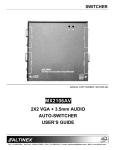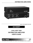
1
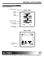
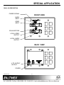
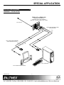
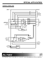
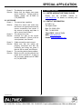
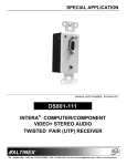
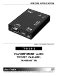
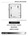
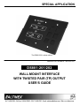
SPECIAL APPLICATION
The DS801-202 is shown above.
MANUAL PART NUMBER: 400-0447-003
DS801-201/202
WALL-MOUNT INTERFACE
WITH TWISTED PAIR (TP) OUTPUT
USER’S GUIDE
SPECIAL APPLICATION
TABLE OF CONTENTS
Page
PRECAUTIONS / SAFETY WARNINGS ............... 2
GENERAL..........................................................2
INSTALLATION .................................................2
CLEANING.........................................................2
FCC NOTICE .....................................................2
ABOUT YOUR DS801-201/202 ............................... 3
TECHNICAL SPECIFICATIONS ............................ 3
DESCRIPTION OF DS801-201/202 ....................... 5
DS801-201 DESCRIPTION................................5
DS801-202 DESCRIPTION................................6
APPLICATION DIAGRAMS...................................... 7
DIAGRAM 1: TYPICAL SETUP ..........................7
DIAGRAM 2: INTERNAL VIEW ..........................8
INSTALLING YOUR DS801-201/202 ..................... 9
OPERATION............................................................... 9
TROUBLESHOOTING GUIDE ................................ 9
NO DISPLAY......................................................9
NO SOUND......................................................10
ALTINEX POLICIES ................................................ 10
LIMITED WARRANTY/RETURN POLICIES.....10
CONTACT INFORMATION ..............................10
400-0447-003
1
SPECIAL APPLICATION
PRECAUTIONS / SAFETY WARNINGS
•
1
Please read this manual carefully before using your
DS801-201/202. Keep this manual handy for future
reference. These safety instructions are to ensure
the long life of your DS801-201/202 and to prevent
fire and shock hazards. Please read them carefully
and heed all warnings.
1.1 GENERAL
•
Qualified ALTINEX service personnel or their
authorized representatives must perform all
service.
1.2 INSTALLATION
•
•
•
•
To prevent fire or shock, do not expose this unit
to water or moisture. Do not place the
DS801-201/202 in direct sunlight, near heaters
or heat-radiating appliances, or near any liquid.
Exposure to direct sunlight, smoke, or steam
can harm internal components.
Handle the DS801-201/202 carefully. Dropping
or jarring can damage the unit.
Do not pull the cables that are attached to the
DS801-201/202.
1.3 CLEANING
•
Clean only with a dry cloth. Never use strong
detergents or solvents such as alcohol or
thinner. Do not use a wet cloth or water to clean
the unit. Do not open the unit to clean.
1.4 FCC NOTICE
•
This device complies with Part 15 of the FCC
Rules. Operation is subject to the following two
conditions: (1) This device may not cause
harmful interference, and (2) this device must
accept any interference received, including
interference that may cause undesired
operation.
400-0447-003
2
This equipment has been tested and found to
comply with the limits for a Class A digital device
pursuant to Part 15 of the FCC Rules. These
limits are designed to provide reasonable
protection against harmful interference when the
equipment is operated in a commercial
environment. This equipment generates, uses,
and can radiate radio frequency energy and if
not installed and used in accordance with the
instruction manual, may cause harmful
interference to radio communications. Operation
of this equipment in a residential area is likely to
cause harmful interference in which case the
user will be required to correct the interference
at his own expense.
Any changes or modifications to the unit not
expressly approved by ALTINEX, Inc. could void
the user’s authority to operate the equipment.
SPECIAL APPLICATION
ABOUT YOUR DS801-201/202
2
TECHNICAL SPECIFICATIONS
DS801-201/202
WALL MOUNT VIDEO + AUDIO TO
TWISTED PAIR (UTP) TRANSMITTER
FEATURES/
DESCRIPTION
GENERAL
The DS801-201/202 provides a means of
transmitting computer video and audio signals over
Twisted Pair-type (CAT-5/6) cable when used
together with an ALTINEX UTP receiver, such as
the DS801-111. Video equalization allows for
transmission over cable lengths up to 400 ft
(122 m). The DS801-202 provides for snap-in
connectors that may be used to route various
computer video, audio, and control signals.
Inputs
RGBHV/YPbPr
Stereo Audio
Power
15-pin HD female
3.5mm female
2-pin terminal block
Output
RGBHV/YPbPr
The DS801-201 is designed to mount into a
standard 2-gang outlet box and the DS801-202 into
a standard 3-gang outlet box. The DS801-201/202
offers a female 15-pin HD input with the native
Plug & Play compatibility and the 3.5 mm Stereo
Audio jack is used for audio input. The female TP
main output provides distributed drive to the UTP
cable. The signal detect feature shows when a
signal is present. The DS801-201/202 also offers a
buffered Local Output for both video and audio.
The front panel provides an attractive finish for the
audio/video inputs and local outputs.
15-pin HD female
Stereo Audio
3.5mm female
Video+ Stereo Audio
RJ-45 female
Compatibility
Signal types
Signal resolutions
ALTINEX – UTP Standard
for TP Series
VGA through UXGA
or 480p, 567p, 720p, 1080i
Table 1. DS801-201/202 General
The latest generation of Twisted Pair devices uses
an innovative, patented technology* developed by
ALTINEX. The new signal processing technology
allows transmitting and receiving fully equalized
computer video signals, stereo, and audio signals
over long distances. The maximum distance at full
UGXA resolution is 400 ft (122 m) between devices
and may reach up to 750 ft (230 m) at VGA
resolution.
* US Patent 7,065,190
400-0447-003
DS801-201/202
3
3
SPECIAL APPLICATION
MECHANICAL
DS801-201/202
ELECTRICAL
DS801-201 Inside Wall Dimensions
DS801-201/202
Input
Height
2.60 in (66 mm)
Video Analog Signal
Width
3.52 in (90 mm)
Video Sync Level
TTL
Depth
1.28 in (33 mm)
Audio Signal Level
1.0 Vp-p max.
DS801-202 Inside Wall Dimensions
Height
Output
2.60 in (66 mm)
Width
5.40 in (137 mm)
Depth**
1.28 in (33 mm)
Video+ Stereo Audio
9 VDC
4.56 in (116 mm)
Width - DS801-202
6.38 in (162 mm)
Height - DS801-201/202
4.50 in (114 mm)
0.338 lb (0.153 kg)
DS801-202
0.387 lb (0.176 kg)
* The front panel uses the standard faceplate
mounting holes on the outlet box.
** The dimensions provided are for the base unit
only. The snap-in depths may vary.
Material
Housing
0.032” Aluminum
Front Panel
0.080” Aluminum
Miscellaneous
T° Operating
10°C-50°C
T° Maximum
75°C
90% noncondensing
38,000 hrs
Humidity
MTBF (calc.)
Table 2. DS801-201/202 Mechanical
400-0447-003
3.6 Watts
Table 3. DS801-201/202 Electrical
Weight
DS801-201
ALTINEX – UTP Standard
for
TP Series
Power
Front Panel (wall surface)*
Width - DS801-201
1.0 Vp-p max.
4
SPECIAL APPLICATION
DESCRIPTION OF DS801-201/202
4
DS801-201 DESCRIPTION
POWER SIGNAL
FRONT VIEW
AUDIO
INPUT
VIDEO
INPUT
EQUALIZATION
LOCAL VIDEO
OUTPUT
LOCAL AUDIO
OUTPUT
BACK VIEW
4 TP OUTPUT
OUTPUT
POWER
400-0447-003
5
SPECIAL APPLICATION
DS801-202 DESCRIPTION
POWER SIGNAL
FRONT VIEW
AUDIO
INPUT
VIDEO
INPUT
EQUALIZATION
LOCAL VIDEO
OUTPUT
LOCAL AUDIO
OUTPUT
BACK VIEW
4 TP OUTPUT
OUTPUT
POWER
400-0447-003
6
SPECIAL APPLICATION
APPLICATION DIAGRAMS
5
DIAGRAM 1: TYPICAL SETUP
DS801-201 or DS801-202
INSIDE WALL PORTION FITS
STANDARD OUTLET BOX OPENINGS
DS801-201 = 2-GANG and DS801-202 = 3-GANG
CAT5 OUTPUT
COMPUTER/COMPONENT VIDEO
AND AUDIO INPUT
LOCAL COMPUTER/COMPONENT
VIDEO AND AUDIO OUTPUT
LOCAL COMPUTER
LOCAL MONITOR AND SPEAKERS
400-0447-003
7
SPECIAL APPLICATION
DIAGRAM 2: INTERNAL VIEW
INPUT
OUTPUT
R
LOCAL
MONITOR
OUTPUT
15-PIN HD
G
B
H
V
COMPUTER/
COMPONENT
VIDEO
15-PIN HD
R
PAIR3
G
PAIR2
B
PAIR1
PLUG AND PLAY
4 - TP
OUT
RJ-45
PAIR4
H/W
V
SYNC
PROCESSING
H
EQ
SIGNAL
DETECT
MONO
LOCAL
STEREO
AUDIO
3.5mm
L
OSC
AUDIO
MODULATION
STEREO
R
L
R
POWER
9VDC, 0.5A
2-PIN TB
400-0447-003
+
GND
POWER
SUPPLY
8
LOCAL
STEREO
AUDIO
3.5mm
SPECIAL APPLICATION
INSTALLING YOUR DS801-201/202
6
OPERATION
7
Step 1. Determine the best location for the
DS801-201/202 and TP Receiver. Where
possible, locate the DS801-201/202 as
close to the video source as possible and
the receiver as close to the receiving
component as feasible.
The DS801-201/202 requires no adjustments for
normal operation. Once connected and the
equalization set, the DS801-201/202 will work
trouble-free with no user intervention. Depending
on the TP receiver, cable lengths between units
should be 400 ft (122 m) or less.
Step 2. Apply power to the 2-pin terminal block on
the rear of the DS801-201/202.
TROUBLESHOOTING GUIDE
We have carefully tested and have found no
problems in the supplied DS801-201/202.
However, we would like to offer suggestions for the
following:
NOTE: The power supply should provide
9 VDC and be capable of
supplying 500 mA.
Step 3. The Power LED should be on and red.
8.1 NO DISPLAY
Step 4. Connect the video and audio sources to
the input of the DS801-201/202 using
high quality cables.
Cause 1:
Solution:
Step 5. The Power LED should change from red
to green indicating a signal is present.
Step 6. Connect a local monitor and speakers to
the local outputs on the DS801-201/202.
These connections are not required for
proper operation of the transmitter, but
are provided for convenience.
Cause 2:
Solution:
Step 7. Run a UTP-type (CAT-5/CAT-5e) cable
from the 4TP OUTPUT on the rear of the
DS801-201/202 Transmitter to the 4TP
INPUT on the TP Receiver.
Cause 3:
Solution:
NOTE: Ensure good signal transmission
by routing the cable so as to
avoid any sharp angles, creases,
or bends.
Cause 4:
Solution:
Step 8. Connect the TP Receiver per its
installation instructions. In the case of the
DS801-111, when the TP signal from the
DS801-201/202 is applied, the Power
LED will turn from red to green.
Step 9. Connect the receiver video and audio
outputs to their respective display and
amplifying devices.
Step 10. The units are now operational.
400-0447-003
8
9
The source has a problem.
Check the source and make sure
there is a signal present and all
source connections are correct. If
the source is working and there is
still no display, see Cause 2.
The path has a problem.
Connect the transmitter directly to
the receiver using a short UTP
patch cable. If the image is good,
there is a problem with the cable.
Otherwise, see Cause 3.
Cable connections are incorrect.
Make sure that cables are properly
connected. Also, make sure that the
continuity and wiring are good. If
there is still no display present, see
Cause 4.
Video equalization required.
Adjust the VIDEO EQUALIZATION
on the transmitter. Long cable runs
may require adjustments to near
maximum.
In general, cable runs less than 50 ft
(15 m) require little or no video
equalization and should be set to
minimum. Cable runs up to 400 ft
(122 m) will require near maximum
equalization on the receiver.
SPECIAL APPLICATION
Cause 5:
Solution:
The display has a problem.
Make sure the display has power
and is turned on. If there is still no
display, please call ALTINEX at
(714) 990-2300.
8.2 NO SOUND
Cause 1:
Solution:
Cause 2:
Solution:
Cause 3:
Solution:
Cause 4:
Solution:
400-0447-003
ALTINEX POLICIES
9
9.1 LIMITED WARRANTY/RETURN POLICIES
Please see the ALTINEX website at
www.altinex.com for details on warranty and
return policies.
9.2 CONTACT INFORMATION
The source has a problem.
Check the source and make sure
that there is a signal present and all
source connections are correct. If
the source is working and there is
still no sound, see Cause 2.
The volume is too low.
Increase the gain at the source
toward maximum. If there is still no
sound present, see Cause 3.
Cable connections are incorrect.
Make sure that the cables are
properly connected and that the
continuity and wiring are good. If
there is still no sound, see Cause 4.
The receiving device has a problem.
Make sure the receiving device has
power and is turned on. If there is
still no sound, please call ALTINEX
at (714) 990-2300.
ALTINEX, Inc.
592 Apollo Street
Brea, CA 92821 USA
TEL: 714 990-2300
TOLL FREE: 1-800-ALTINEX
WEB: www.altinex.com
E-MAIL: [email protected]
10