1
PRECAUTIONS
Read the Operating Instructions carefully and completely before
operating the unit. Be sure to keep the Operating Instructions
for future reference. All warnings and cautions in the Operating
Instructions and on the unit should be strictly followed, as well
as the safety suggestions below.
Installation
1 Water and moisture — Do not use this unit near water, such
as near a bathtub, washbowl, swimming pool, or the like.
2 Heat — Do not use this unit near heat sources, including
heating vents, stoves, or other appliances that generate heat.
It also should not be placed in temperatures less than 5°C
(41 ‘F) or higher than 35°C (95”F).
3 Mounting surface — Place the unit on a flat, even sutiace.
4 Ventilation — The unit should be situated with adequate
space around it so that proper heat ventilation is assured.
Allow 10 cm (4 in.) clearance from the rear and the top of the
unit, and 5 cm (2 in.) from each side.
- Do not place the unit on a bed, rug, or similar surface that
may block the ventilation openings.
- Do not install the unit in a bookcase, cabinet, or airtight
rack where ventilation may be impeded.
5 Objects and liquid entry —Take care that objects or liquids
do not get inside the unit through the ventilation openings.
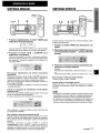
6 Carts and stands — Whenplaced or mounted on a stand
or cart, the unit should be
moved with care.
Quick stops, excessive force,
and uneven surfaces
may
cause the unit or cart to overturn
or fall.
7 Wall or ceiling mounting —The unit should not be mounted
on a wall or ceiling, unless specified in the Operating
Instructions.
Electric Power
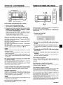
Owner’s record
For your convenience, record the model number and serial
number (you will find them on the rear of your unit) in the space
provided below. Please refer to them when you contact your
Aiwa dealer in case of difficulty.
Model No.
AV-X120
1
ENGLISH
Serial No. (Lot No.)
{
1 Power sources — Connect this unit only to power sources
specified in the Operating Instructions, and as marked on
the unit.
2 Polarization — As a safety feature, some units are equipped
with polarized AC power plugs which can only be inserted
one way into a power outlet. If it is difficult or impossible to
insert the AC power plug into an outlet, turn the plug over
and try again. If it is not still inserted easily into the outlet,
please call a qualified service technician to service or replace
the outlet. To avoid defeating the safety feature of the
polarized plug, do not force it into a power outlet.
3 AC power cord
- When disconnecting the AC power cord, pull it out by the
AC power plug. Do not pull the cord itself.
- Never handle the AC power plug with wet hands, as this
could result in fire or shock.
- Power cords should be firmly secured to avoid being
severely bent, pinched, or walked upon. Pay particular
attention to the cord from the unit to the power socket.
- Avoid overloading AC power plugs and extension cords
beyond their capacity, as this could result in fire or shock.
4 Extension cord — To help prevent electric shock, do not
use a polarized AC power plug with an extension cord,
receptacle, or other outlet unless the polarized plug can be
completely inserted to prevent exposure of the blades of the
plug.
5 When not in use — Unplug the AC power cord from the AC
power plug if the unit will not be used for several months or
more. When the cord is plugged in, a small amount of current
continues to flow to the unit, even when the power is turned
off.
TABLE OF CONTENTS
Outdoor Antenna
PREPARATIONS
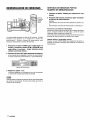
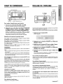
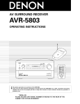
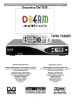
1 Power lines — When connecting an outdoor antenna, make
sure it is located away from power lines.
2 Outdoor antenna grounding — Be sure the antenna system
is properly grounded to provide protection against unexpected
voltage surges or static electricity build-up. Article 810 of the
National Electrical Code, ANS1/NFPA70, provides information
on proper grounding of the mast, supporting structure, and
the lead-in wire to the antenna discharge unit, as well as the
size of the grounding unit, connection to grounding terminals,
and requirements for grounding terminals themselves.
Antenna
Grounding
According
to the National
Electrical
Code
~
I
SOUND
CUSTOM AUDIO ADJUSTMENT ...................................... 7
ELECTRONIC GRAPHIC EQUALIZER ............................. 8
DSP SURROIJND ................................................................ 8
BASIC OPERATIONS
ANTENNA LEAD IN WIRE
RADIO RECEIPTION
ANTENNA DISCHARGE UNIT
(NEC SECTION 810-20)
ELECTRIC
CONNECTIONS .................................................................. 3
BEFORE OPERATION ....................................................... 6
SETTING THE CLOCK ....................................................... 6
SELECTION OF AUDIO/VIDEO SOURCE ........................ 9
RECORDING AN AUDIO SOURCE ................................... 9
T
I
PRECAUTIONS ................................................................... 1
/11
MANUAL TUNING ............................................................ 10
DIRECT TUNING ................................................................ 10
PRESElllNG STATIONS ............... .................................. 11
DOLBY PRO LOGIC
SELECTING DOLBY PRO LOGIC ................................... 12
ADJUSTING SPEAKER LEVEL BALANCE. ................... 13
-?
ELECTRODE SYSTEM
(NEC ART 250 PART H)
NEC-NATIONAL
ELECTRICAL
CODE
TIMER
SETTING THE SLEEP TIMER .......................................... 14 m
Maintenance
GENERAL
Clean the unit only as recommended
Instructions.
in the Operating
CARE AND MAINTENANCE .......... .................................. 14
SPECIFICATIONS ............................................................ 15
TROUBLESHOOTING GUIDE .......................................... 16
Damaue Reuuirina Service
Have the unit serviced by a qualified service technician if:
- The AC power cord or plug has been damaged
- Foreign objects or liquid have gotten inside the unit
- The unit has been exposed to rain or water
- The unit does not seem to operate normally
- The unit exhibits a marked change in performance
- The unit has been dropped, or the cabinet has been damaged
DO NOT ATTEMPT TO SERVICE THE UNIT YOURSELF.
PARTS INDEX ................................................................... 16
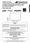
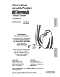
Check your unit and accessories
AV-X120 Stereo receiver
Remote control
~
::
$
N
FM antenna
AM antenna
e
Operating Instructions, etc.
ENGLISH
2
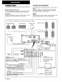
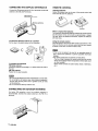
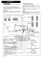
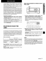
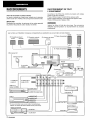
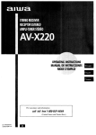
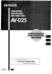
CONNECTIONS
CONNECTING
EQUIPMENT
Jacks and plugs of the connecting cord are color-coded as
follows:
Red jacks and plugs : For the right channel of audio signals
White jacks and plugs: For the left channel of audio signals
Yellow jacks and plugs: For video signals
Before connecting the AC cord
The rated voltage of your unit shown on the rear panel is 120 V
AC. Check that the rated voltage matches your local voltage.
m
IMPORTANT
Connect the speakers, antennas, and all other external
equipment first. Then connect the AC cord at the end.
Insert the plugs fully into the jacks. Loose connections
produce a humming sound or other noise interference.
The numbers in the illustration below correspond to the following details.
Right
may
Left
J
Left
I
h
.-+!iq
k@xGYa6)(a I
II
n
L AUDIOIN R
II
‘Y’11
‘x
L
Video 1
,=
+
~~~=
to VIDEO IN
* When connecting a monaural video, use a
stereo-mono connecting cord (not supplied).
Tape deck
~[
[~[
J
I
—
to AUDIO
OUTPUT ~;
~ to VIDEO )IN
L
/
I I
to LINE IN
~
J
3
TV
-
,qB-
D
to OUTPUT
~11111.e
ENGLISH
-
to LINE OUT
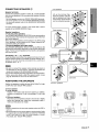
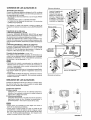
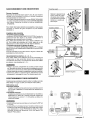
CONNECTING
SPEAKERS
@)
Speaker terminals
Connect front speakers (system A and/or B), a center speaker
and surround speakers to the corresponding speaker terminals
on the unit:
- the front speaker cords to the FRONT SPEAKERS terminals
- the center speaker cord to the CENTER SPEAKER terminals
- the surround speaker cords to the SURROUND SPEAKERS
terminals.
Front speakers
h
Lift up the terminal flap,
inserf the speaker cord lead
into the terminal slot, then
close the flap. Check that the
cord is connected securely.
For more powerful bass, connect a sub woofer with a built-in
amplifier to the SUPER WOOFER 4 jack.
Center speaker
Speaker impedance
● Front and center
speakers
The SPEAKER IMPEDANCE SELECTOR on the rear should be
set to the position that matches the impedance value of the front
and center speakers.
When using 4 ohm speakers, set the selector to 4Q. When using
8 ohm speakers, set the selector to 8Q. Please unplug the AC
cord before setting the selector.
● Surround
speakers and super woofer
The SPEAKER IMPEDANCE SELECTOR has no effect on the
SURROUND SPEAKERS terminals and the SUPER WOOFER
Q jack. For the surround speakers and sub woofer, use speakers
of 8 ohms or more.
\
.
-
——
Connecting + to +, - to - terminals
To get the proper sound effect, the speaker terminals on the unit
and the speaker should be connected with proper polarity; the+
terminal on the unit should be connected to the + terminal on
the speaker (and – to –).
m
* Be sure to connect the speaker cords correctly as shown in
the illustration on the right column. Improper connections can
cause short circuits in the SPEAKER(S) terminals.
* Do not leave objects generating magnetism near the speakers.
● When
using a sub woofer, select the speaker system A (see
page 6). Otherwise no sound can be heard from it.
Q
0
Sub woofer
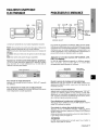
POSITIONING
THE SPEAKERS
Position the speakers to make the most of the Dolby Pro Logic
or DSP effect (see “DOLBY PRO LOGIC”).
Surround speakers
@ Front speakers
@ Center speaker
Position in the center of the two front speakers. in addition,
position on or below the TV set, if connecting a TV set to the
unit.
@ Surround speakers
Place the surround speakers directly to the side of or slightly
behind the listening area. Align them horizontally, about 1
meter (3.2 feet) above ear height.
m
Sound is heard from the surround speakers when the DSP is
set to on.
● Sound is heard from the center speaker mainly when the Dolby
Pro Logic is set to on. Note that when you select the PHANTOM
mode of the Dolby Pro Logic, the center speaker is muted.
(For details, see “DOLBY PRO LOGIC).
●
ENGLISH
4
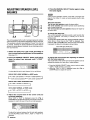
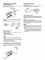
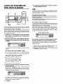
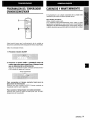
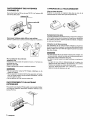
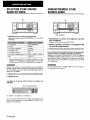
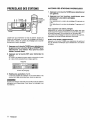
CONNECTING THE SUPPLIED ANTENNAS @
REMOTE CONTROL
Connect the FM antenna to the FM 75 Q terminals and the AM
antenna to the AM LOOP terminals.
Inserting batteries
Detach the battery cover on the rear of the remote control and
insert two R6 (size AA) batteries.
FM antenna
antenna
R6(’AA)
When to replace the batteries
The maximum operational distance between the remote control
and the sensor on the unit should be approximately 5 meters
(16 feet). When this distance decreases, replace the batteries
with new ones.
To stand the AM loop antenna on a surface
Fix the claw to the slot as shown in the illustration.
...
,..-..OQ
.......
Using the remote control
The instructions in this manual refer mainly to the buttons on the
main unit. Buttons on the remote control with the same names
as those on the main unit can be used as well.
%
ali!ii!
1
,,;,’:;;”
.-’.:,,
,,:,,]
.,,
,,j,y
,/
,.
/,
●
\
●
To position the antennas
FM feeder antenna:
Extend this antenna horizontally in a T shape and fix its ends to
the wall.
AM loop antenna:
Position for the best reception.
●
●
●
Do not bring the FM antenna near metal objects or curtain rails.
Do not bring the AM antenna near other external equipment,
the unit itself, the AC power cord or speaker cords, as noise
will be picked up.
Do not unwind the AM loop antenna wire.
CONNECTING
AN OUTDOOR ANTENNA
For better FM reception,
use of an outdoor antenna is
recommended. Connect the outdoor antenna to the FM 75 Q
terminals.
5
ENGLISH
[f the unit is not going to be used for an extended period of
time, remove the batteries to prevent possible electrolyte
leakage.
The remote control may not operate correctly when:
- The line of sight between the remote control and the remote
sensor in the display window is exposed to intense light, such
as direct sunlight.
- Other remote controls are used nearby (those of television,
etc.)
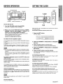
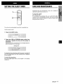
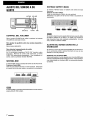
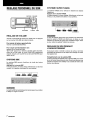
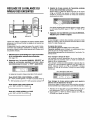
BEFORE OPERATION
TAPE MONITOR
POWER I FUNCTION buttons
SETTING THE CLOCK
CL?CK
VOLUME
1,3,5
-t-l
PHONES
1
!
FRONT SPEAKERS A, B
r
To turn the unit on
2,4
1 Turn the VOLUME control toward MIN.
Otherwise, the speakers may be damaged.
2 Press one of the FUNCTION buttons (TUNER,
PHONO, AUX/TV, CD, VIDEO 1, VIDEO 2 or
VIDEO 3) or the TAPE MONITOR button.
When pressing the TUNER button, the previously tuned
station is received (Direct Play Function).
The POWER button is also available.
Operation is possible after four seconds.
When the AC cord is connected for the first titme, the clock on
the display flashes.
Set the time aa ‘follows while the power is off.
1 Press the SET button.
The hour flashes.
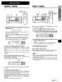
To select the front speaker system
To use speaker system A: Set the FRONT SPEAKERS A button
to sON.
To use speaker system B: Set the FRONT SPEAKERS B button
to wON.
To use both speaker systems : Set both the buttons to *ON.
Set the button(s) to mOFF to turn off the speaker system(s).
m
As the front speaker systems A and B are connected in series:
- The sound will be slightly decreased when using both speaker
systems
- No sound can be heard if the FRONT SPEAKERS A and B
buttons are set to w ON when only one speaker system is
connected
To change a displayed name for the AU)UTV button and
VIDEO 2 button
When the AUX/TV button is pressed, AUX is displayed initially.
It can be changed to TV.
With the power on, press the POWER button while pressing the
AUXfW button.
2
3 Press the SET button to set the hour.
The hour stops flashing
4 Press the [)OWN7
the minute.
and the minute starts flashing.
or
UPA button to designate
5 Press the SET button to set the minute.
The minute stops flashing on the display and the clock starts
from 00 second.
To correct the current time
Press the POWEERbutton to turn the unit off, Press the SET
button and carry out steps 1 to 5 above.
To display the current time
Press the CLOCK button on the remote control. The clock is
displayed for 4 seconds.
The displayed name for VIDEO 2 button can be changed to
VIDEO 2, LD or MD; with the power on, press the POWER button
while pressing the VIDEO 2 button.
To switch to the 24-hour standard
Press the POWER button while pressing the UPA or DOWNY
button while the current time is displayed.
Repeat the same procedure to restore the 12-hour standard.
Using the headphones
Connect headphones to the PHONES jack with a standard stereo
plug (06.3 mm, 1/4 inch). Be sure to set the FRONT SPEAKERS
A and B buttons to 10FF. Otherwise sound is output from the
speakers.
If the clock dislplay flashes while the power is off
This is caused by a power interruption.The current time needs
to be reset.
If power is interrupted for more than approximately 24 hours, all
settings stored in memory after purchase need to be reset.
m
When using the headphones, set the Dolby Pro Logic and DSP
system to off.
To turn the unit off
Press the POWER button.
ENGLISH
6
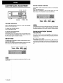
CUSTOM AUDIO ADJUSTMENT
MUTl~G V?LUME
BAtiNCE
T-BASS
BBE
SUPER T-BASS SYSTEM
The T-BASS system enhances the realism of low-frequency
sound.
Press the T-BASS button.
Each time it is pressed, the level changes. Select one of the
three levels, or the off position to suit your preference.
L
1111
111111
h+=+=+(=)
1
VOLUME CONTROL
Turn the VOLUME control on the unit, or press the VOLUME
buttons on the remote control.
To adjust the Iefthight balance
m
Low-frequency sound may be distorted when the T-BASS system
is used for a disc or tape in which low-frequency sound is
originally emphasized. In this case, cancel the T-BASS system.
Turn the BALANCE control.
To mute the sound temporarily
Press the MUTING button.
“MUTE ON” appears on the display for four seconds. While muting
the sound, the selected FUNCTION button flashes. Press the
MUTING button again to restore the sound.
BBE SYSTEM
111111
+m+mm-+ma+mm , (cancel)1
I
DURING
The output volume and tone (except BBE) of the speakers or
headphones may be freely varied without affecting the level of
the recording.
Recording with the BBE
The BBE system enhances the clarity of high-frequency sound.
Press the BBE button.
Each time it is pressed, the level changes. Select one of the
three levels, or the off position to suit your preference.
II
SOUND ADJUSTMENT
RECORDING
1111
is automatically canceled when Dolby Pro Logic
The desired source can be recorded with the BBE function to
enhance the clarity of high-frequency sound. When playing back
a tape recorded with BBE, it is recommended that BBE be set to
off.
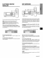
ELECTRONIC
EQUALIZER
GRAPHIC
DSP SURROUND
DSP
DOWNV
UPA
I
MANUAL SELECT
This unit provides the following five different equalization modes.
ROCK: Powerful sound emphasizing treble and bass
POP: More presence in the vocals and midrange
JAZZ: Accented lower frequencies for jazz-type music
CLASSIC: Enriched sound with heavy bass and fine treble
BGM: Calm tone with suppressed bass and treble
Press one of the GEQ (Graphic Equalizer) buttons.
The selected mode name appears on the display for two seconds,
and the selected mode on the right side of the display is enclosed
with parentheses.
To select with the remote control
Press the GEQ button repeatedly until the desired equalization
mode is displayed.
LA
The DSP (Digital Signal Processor) surrcmnd circuits can recreate
the effect of sounds reflected from walls or ceilings, to obtain the
sound presence of real environments. There are four modes with
matching graphic equalization modes. Equalization modes are
selected automatically and can also be selected or turned off to
suit your preference.
Press one of the DSP buttons (DANCE, LIVE, HALL
or ARENA).
The selected mode name appears on the display for two seconds,
and the selected DSP and matching GEQ modes on the display
are enclosed with parentheses.
Q mode
Selected mode —~
To cancel the selected mode
Press the selected button again. “GEQ oFF appears on the
display.
DSP
e3
m
When the music source is monaural
Select LIVE to obtain a simulated stereo effect. When DANCE
or HALL is selected, no sound will be heard from the surround
speakers.
To cancel the selected mode
Press the selected button again. “DSP oFF appears on the
display. Even if canceling the selected DSP mode, the matching
or selected GEQ mode still remains. While the DSP surround
system is off, no sound is heard from the surround speakers.
To select with the remote control
Press the DSP button repeatedly until the desired DSP mode is
displayed.
To adjust the volume of the surround spe!akers
Press the MANUAL SELECT button once. “SIJR” is displayed
for four seconds. Press the UPA or DO\NNV buttonwhile “SUR”
is displayed.
Note that the Dolby Pro Logic surround speakers level is also
changed (see page 13).
m
The DSP system is automatically
PRO LOGIC is turned on.
canceled when the DOLBY
ENGLISH
8
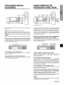
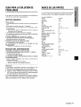
SELECTION
SOURCE
OF AUDIO/VIDEO
RECORDING
AN AUDIO SOURCE
1
1
00=000
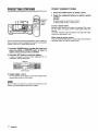
1 Select the program source to be recorded.
Press one of the FUNCTION buttons.
1 Select the program source.
2 Set the tape deck or MD recorder to the recording
mode.
Press one of the FUNCTION buttons or the TAPE MONITOR
button.
3 Start the selected
Radio
I TUNER
Record
I PHONO
To monitor recorded sound during recording (when the
connected tape deck is a three-head system)
I Television, etc.
I AUXiTVaj
I
I Com~act disc
I CD
I
Video (VCR or LD)
MD
] VIDEO 2’)
When using a turntable with a built-in equalizer amplifier, set the
switch of the equalizer amplifier to off. See the instructions of
the turntable for further information.
2 Start the selected program source.
3 Adjust the sound.
About the video source to the monitor or TV
Selected VIDEO source
VI: VIDEO 1, V2: VIDEO 2, V3: VIDEO 3
The selected video source is indicated on the display and the
video signal through the MONITOR VIDEO OUT jack is output
on the TV.
ENGLISH
Press the TAPE MONITOR button. “TAPE ON” appears on the
display for four seconds, and then the source name selected in
step 1 comes back on. To cancel the tape monitor, press it again
so that “TAPE oFF appears.
VIDEO 1, VIDEO 2a),VIDEO 3
a):For selecting AUmV, or VIDEO 2/LD/M D, see “TOchange
a displayed name for the AUX/TV button and VIDEO 2
button” of “BEFORE OPERATION” (see page 6).
9
program source.
Any sound control except the BBE system has no effect on
recording (see page 7).
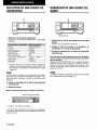
MANUAL TUNING
DIRECT TUNING
MONO
TUNER
Numbered
buttons
*
POWER
1
09QC2
C2C20C)
,00
2
Ill
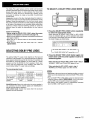
1 Press the TUNER button repeatedly to select the
desired band.
Ffvf~
AM
1-
1
When the TUNER button is pressed while the power is off,
the power is turned on directly.
2 Press the
UPA or DOWNY
When you know the frequency of the desired station, you can
tune in directly to the station.
1 Press the TUNER button to select a band.
2 Press the TUNER button and hold it down until
“—“ flashes on the display (Direct Tuning Mode).
button to select a
station.
Each time the button is pressed, the frequency changes.
When a station is received, “TUNE” is displayed for two
seconds. During FM stereo reception, ([[011) is displayed.
3 Press the appropriate numbered
in to the desired station.
buttons to tune
Example:
To tune in to 106.50 MHz, press 1, 0, 6, 5 and O buttons.
To tune in to 95.2 MHz, press 9, 5, 2 and Q buttons.
To search for a station quickly (Auto Search)
Keep the UPA or DOWNY button pressed until the tuner starts
searching for a station. After tuning in to a station, the search
stops.
To stop the Auto Search manually, press the UPA or DOWNT
button,
●
The Auto
Search
may not stop
at stations
with very
To cancel the Direct tuning mode
Press the UPA or DOWNY button.
When using the remote control
Carry out steps 1 and 2 above, and press the numbered buttons
on the remote control to tune in to the desirecl station.
weak
signals.
●
When an FM stereo broadcast contains noise
Press the MONO TUNER button on the remote control so that
“MONO appears on the display.
Noise is reduced, although reception is monaural.
●
When entering a frequency out of tuning range, the value
flashes for two seconds and then goes off. Check the frequency
and repeat step 3 correctly.
When entering a frequency not covered by the tuning interval,
the value is automatically rounded up or down to the closest
one covered by it.
To restore stereo reception, press the button so that “MONO
disappears.
To change the AM tuning interval
The default setting of the AM tuning interval is 10 kHz/step. If
you use this unit in an area where the frequency allocation system
is 9 kHz/step, change the tuning interval.
Hold down the TUNER button and press the POWER button
immediately. Note that the unit is set to the Direct Tuning mode if
the TUNER button is pressed and held down for about two
seconds.
To reset the interval, repeat this procedure.
ENGLISH 1 ~
m
PRESETTING
STATIONS
PRESET NUMBER TUNING
1 Press the TUNER
button to select a band.
2 Press the numbered
buttons to select a preset
number.
Example:
To select preset number 25, press 2 and 5.
To select preset number 7, press O and 7.
To clear a preset station
Select the preset number of the station to be cleared. Then, press
the SET button, and prees the SET button again within four
seconds.
The preset numbers of all other stations in the band with higher
numbers are decreased by one.
When using the remote control
The unit can store a total of 32 preset stations. When a station is
stored, a preset number is assigned to the station. Use the preset
number to tune in to a preset station directly.
1 Press the TUNER button to select the band, and
mess the UPA or DOWNV button to select a
station. Direct tuning is also available.
2 Press the SET button to store the station.
A station is assigned a preset number, beginning from 1 in
consecutive order for each band.
Preset number
3 Repeat steps 1 and 2.
No more stations will be stored if a total of 32 stations have
already been stored for all the bands.
m
When the AM tuning interval is changed, all preset stations are
cleared. The preset stations have to be set again.
1 I
ENGL/SH
Press the TUNER BAND button to select a band, then press the
numbered buttons to select a preset number.
The Dolby Pro Logic feature and the center and surround
speakers (standard) assure full-scale home theater sound. When
playing back laser discs or video software that have been
recorded in Dolby Surround, astonishingly
realistic sound
surrounds the listener to create a new level of audio/visual
entertainment.
Independent control of the four channels allows the listener to
enjoy the same type of sound reproduction experienced in movie
theaters. Voices are reproduced in the front and center sound
field, while ambient sounds like cars and crowds are reproduced
on all sides of the listener for an incredibly lifelike audio/video
experience. Please read the following carefully to “tune” the
system’s output to match the characteristics of your listening
space.
Check the following:
~ Before using the DOLBY PRO LOGIC, adjust the proper
balance of the speaker sound levels (see page 13).
●
●
●
TO SELECT A DOLBY PRO LOGIC MODE
“1,2
1 Press the DOLBY PRO LOGIC button repeatedly
to select tlhe appropriate mode.
When selecting the DOLBY PRCi LOGIC or 3CH LOGIC
mode, the indicator lights up, and the selected mode name
runs through on the display. Each time the button is pressed,
the mode changes as shown below.
Make sure the speakers are properly connected and positioned
(see pages 3 and 4).
Make sure the TV set and video unit are properly connected
(see page 3).
Make sure the laser disc and video tape, etc., support
m_j@LSY5URRCUND\
.
r
SELECTING DOLBY PRO LOGIC
DOLBY PRO LOGIC+F
3CH LOGIC
DC)LBYPRO LOGIC oFF (cancel) 2
2 Press the DOLBY PRO LOGIC button again and
hold it down until the center speaker m;de to be
selected appears.
The optimal Dolby Pro Logic mode depends on the type and
placement of the speakers. It is recommended that the optional
Aiwa speakers should be used for all channels, for example, the
SX-RI 000 for surround speakers, the SX-C1 000 for a center
speaker and the SX-AVI 000 for front speakers. Check your
current type and placement of the speakers and select the
recommended Dolby Pro Logic mode accordingly.
The recommended
When selecting the DOLBY PRO LOGIC mode in step 1:
“NORMAL’, “WIDE and “PHANTOM” appear in turn.
When selecting the 3CH LOGIC Imode in step 1:
“NORMAL!’ and “WIDE appear one after another.
mode
Center speaker
Larger-size
Smaller-size
No speaker
Surround speaker
(Rear speaker)
DOLBY PRO
LOGIC-WIDE
DOLBY PRO
LOGIC-NORMAL
PHANTOM
No surround
speaker
3CH LOGICWIDE
3CH LOGICNORMAL
●
●
●
PHANTOM mode: Select this mode when the center speaker is
not connected. All center channel signals are redistributed to
the left and right channel speakers.
3CH LOGIC mode: Select this mode when the surround
speakers are not connected.
Depending on the sound source or listening condition, surround
effect may not be obtained even when the DC)LBY PRO LOGIC
is on.
The full DOLBY PRO LOGIC effect cannot be obtained when
using the software without DOEE!ZZSS= mark. In this case,
use the DSP surround system instead (see page 8).
The DOLBY PRO LOGIC system is automatically canceled
when the BBE or DSP system is turned on.
ENGLISH12
Im
ADJUSTING
BALANCE
SPEAKER LEVEL
4 Press the MANUAL SELECT button again to stop
the noise signal.
If the surround speakers volume of the DSP is changed (see
page 8), the Dolby Pro Logic surround speakers level is also
changed.
About the channels
The left and right speakers create the stereo effect.
The center speaker helps achieve precise sound positioning
over a broad sound field.
The rear-mounted surround speakers enhance the “depth”of
the sound field.
To change the delay time
The unit is equipped with a built-in test signal generator called a
noise sequencer for easy balance adjustment of all four channels.
The sequencer outputs a noise signal that “travels” from channel
to channel, enabling the simple adjustment of sound level to
achieve the same apparent loudness, at your listening position,
from each channel.
The surround speakers reproduce sounds a split second after
the front speakers. The delay is initially
set to 20 ms
(milliseconds).
To change this standard delay time, press the MANUAL SELECT
button twice or three times so that “TIME” is displayed. Then,
press the UPA or DOWNY button. Each time one of the buttons
is pressed, the delay time changes as shown below.
15ms -
20ms -
30ms
Select the Dolby Pro Logic mode according to
your current type and placement of the speakers.
(See page 12.)
Press the MANUAL SELECT button and hold it
down for about two seconds until “L TEST”
appears.
To change the sound levels after adjusting the balance
with the noise sequencer
The sound levels of the center and surround speakers can be
adjusted during play of a laser disc or video software.
1 Press the MANUAL SELECT button once or twice to select
“CEN” or “SUR” (center or surround).
2 While the “CEN or “SUR” is displayed, press the UPA or
DOWNV button to adjust the volume.
A noise signal is sent to each channel in turn as follows:
DOLBY PRO LOGIC NORMAL or WIDE mode
r
L TEST: (Left speaker)~TEST
SUR: (Surround speaker)+
R: (Right speaker
CEN: (Center speaker)u
DOLBY PRO LOGIC PHANTOM mode
~LTEST-TEST
R_SUR-1
3CH LOGIC NORMAL or WIDE mode
~LTEST-TEST
R+CEN---l
Adjust the sound level of the center
surround speakers.
and (or)
While “CEN” or “SUR” is displayed, press the UPA or
DOWNY button to adjust the volume of the center or surround
speakers to match the level of the left and right speakers.
To adjust the balance between the left and right speakers,
use the BALANCE control while “L TEST” or “TEST R“ is
displayed.
n
td
ENGLISH
SETTING THE SLEEP TIMER
CARE AND MAINTENANCE
-
Occasional care and maintenance of the unit is needed to
optimize the performance of your unit.
1
To clean the cabinet
Use a soft dry cloth.
If the surfaces are extremely dirty, use a soft cloth lightly
moistened with mild detergent solution. Dc) not use strong
solvents, such as alcohol, benzine or thinner as these could
damage the finish of the unit.
2
The unit can be automatically turned off at a specified time.
Use the remote control.
1 Press the SLEEP button.
2 Press the UP> or DOWN< button within four
seconds to specify the time until the power is
turned off.
Each time the button is pressed, the time changes between 5
and 240 minutes in 5-minute steps.
Specifi:d
time
To check the time remaining until the power is turned off
Press the SLEEP button once. The remaining time is displayed
for four seconds.
To cancel the sleep timer
Press the SLEEP button twice so that “SLEEP” on the display
disappears.
ENGLISH
14
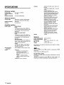
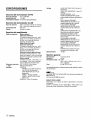
SPECIFICATIONS
outputs
FM tuner section
Tuning range
Usable sensitivity
(IHF)
Antenna terminals
87.5 MHz to 108 MHz
13.2 dBf
75 ohms (unbalanced)
AM tuner section
Tuning range
Usable sensitivity
Antenna
530 kHz to 1710 kHz (10 kHz step),
531 kHz to 1602 kHz (9 kHz step)
350 pV/m
Loop antenna
Amplifier section
Power output
[Stereo Mode]
Front
Min. RMS at 4
or 8 ohms, from 40 Hz to 20 kHz, with
no more than 0.8°A Total Harmonic
Distortion
[Dolby Pro Logic Mode]
Front
70 watts per channel, Min. RMS at 4
or 8 ohms, from 40 Hz to 20 kHz, with
no more than 0.9’%.Total Harmonic
Distortion
Rear (Surround)
35 watts per channel, Min. RMS at 8
ohms, 1 kHz, with no more than 0.9’7.
Total Harmonic Distortion
Center
70 watts, Min. RMS at 4 or 8 ohms, 1
kHz, with no more than 0.97. Total
Harmonic Distortion
0.07 % (50 W, 1 kHz, 8 ohms, Front)
75 watts per channel,
Total harmonic
distortion
Inputs
15
ENGLISH
Muting
AUDIO OUT (REC OUT): 230 mV (2
kohms)
VIDEO OUT (MONITOR): 1 Vp-p (75
ohms)
SUPER WOOFER: 3.1 V
FRONT SPEAKERS IMP: 8Q/4Q
selectable (front speakers A and B):
With the SPEAKER IMPEDANCE
SELECTOR set to 4Q, accepts
speakers of 4 ohms.
With the SPEAKER IMPEDANCE
SELECTOR set to 8S2,accepts
speakers of 8 ohms or more.
SURROUND SPEAKERS IMP: 8Q
(surround speakers): accepts
speakers of 8 ohms or more
CENTER SPEAKER IMP: 8Q/4!2
selectable
With the SPEAKER IMPEDANCE
SELECTOR set to 4!2, accepts
speaker of 4 ohms.
With the SPEAKER IMPEDANCE
SELECTOR set to 8Q, accepts
speaker of 8 ohms or more.
PHONES (stereo jack): accepts
headphones of 32 ohms or more
–20 dB
General
Power requirements
Power consumption
Dimensions
(W XHXD)
Weight
120 V AC, 60 Hz
160 W
360 x 153.5 x 335 mm (14’/1 x 61/s
x 137/4 in.)
8.5 kg (18 lb 12 OZ.)
Specifications and external appearance are subject to change
without notice.
BMSYSTEM
AUDIO IN
PHONO: 2.8 mV (50 kohms)
CD: 370 mV (50 kohms)
TAPE MONITOR: 200 mV (25
kohms)
VIDEO 1, VIDEO 2/LD/MD,
VIDEO 3, AUX/TV 370 mV (50
kohms)
VIDEO IN: 1 Vp-p (75 ohms)
The word “BBE” and the “BBE symbol” are trademarks of BBE
Sound, Inc.
Under license from BBE sound, Inc.
DOLBY PRO LOGIC
Manufactured under license from Dolby Laboratories Licensing
Corporation.
“DOLBY the double-D symbol 00 and “PRO LOGIC” are
trademarks of Dolby Laboratories Licensing Corporation.
TROUBLESHOOTING
If the unit fails
to perform
GUIDE
as described
in these Operating
Instructions, check the following guide.
GENERAL
There is no sound.
● Is the AC cord connected properly?
● Is there an incorrect connection? (+
page 3)
● There may be a short circuit in the speaker terminals.
+ Disconnect the AC cord, then correct the speaker
connections.
● Was an incorrect function
button pressed?
● Are the FRONT
SPEAKERS A and B buttons set correctly?
(+ page 6)
Sound is emitted from one speaker only.
● Is the BALANCE control set appropriately?
● Is the other speaker disconnected?
Sound is heard at a very low volume.
● Has the MUTING button been pressed?
An erroneous display or a malfunction occurs.
~ Reset the unit as stated below.
TUNER SECTION
There is constant, wave-like static.
● Is the antenna connected properly? (+
page 5)
● Is the signal weak?
- Connect an outdoor antenna.
The reception contains noise interference or the sound is
distorted.
● Is the system picking up external noise or multipath distortion?
-+ Change the orientation of the antenna.
* Move the unit away from other electrical appliances.
PARTS INDEX
Instructions about each part on the unit or remote control are
indicated on the pages listed bellow.
(in alphabetic order)
Parts
ALDVTV
BALANCE
BBE
CD
CLOCK
DOLBY PRO LOGIC
DOWN Y (<)
DSP
FRONT SPEAKERS A, B
GEQ
MANUAL SELECT (TEST)
MONO TUNER
MUTING, MUTE
PHONES
PHONO
POWER
SET
SLEEP
SPEAKER IMPEDANCE
SELECTOR
TAPE MONITOR
T-BASS
TUNER, BAND DIRECT
UP A (>)
VIDEO 1
VIDEO 2, LD/MD
VIDEO 3
VOLUME (V, A)
Pages
6, 9
7, 13
7
6, 9
6
12, “13
6,8,10,11,13,14
8
6
8
8, 1:3
10
7
6
6,9
6,10
6, 1‘1
14
4
6, 9
7
6,9,10,11
6,8,10,11,13,14
6, 9
6, 9
6, 9
7
To reset
If an unusual condition in the display window or malfunction
occurs, reset the unit as follows.
1 Press the POWER button to turn off the power.
2 Press the POWER button while pressing the SET button.
Everything stored in memory after purchase is canceled.
If the power cannot be turned off in step 1 because of a
malfunction, reset by disconnecting the AC cord and carry out
step 2.
ENGLISH
I6
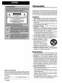
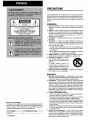
PRECAUCIONES
Antes de utilizar la unidad, lea cuidadosa y completamente este
manual instrucciones. Guarde el manual de instrucciones para
futuras referencias. Todos Ios avisos y precauciones del manual
de instruccionea y de la unidad deberan seguirse estrictamente,
asi como Ias sugerencias de seguridad indicadas a continuation.
Instalacion
1 Agua y humedad — No utilice esta unidad cerca dei agua,
como al Iado de una bafiera, un Iavabo, una piscina, etc.
2 Calor — No utilice esta unidad cerca de fuentes termicas,
como salidas de calefaccion, estufas, ni demas aparatos que
generen calor.
Tampoco debera someterse a temperatures inferiors a 5°C
(41 “F) ni superiors a 35°C (95”F).
3 Superficie de rmontaje — Coloque la unidad sobre una
superficie plana y nivelada.
4 Ventilation
— La unidad debera colocarse donde tenga
espacio suficiente a su alrededor para asegurar su ventilation
adecuada. Deje un espacio Iibre de 10 cm en la parte posterior
y superior de la unidad, y de 5 cm a cada Iado.
- No la coloque sobre una cama, una alfombra, ni nada similar
que pueda bloquear Ias aberturas de ventilation,
- No la instale en una Iibreria, un armario, ni un bastidor
cerrado, donde la ventilation podria ser deficient.
5 Entrada de objetos y Iiquidos — Tenga cuidado de que en
el
interior de la unidad no entren objetos pequefios ni
Iiquidos a traves de Ias aberturas de ventilation.
6 Carritos y estantes — Cuando
haya colocado o montado la unidad
sobre un estante o un carrito,
debera moveria con cuidado.
\
Las paradas repentinas, la fuerza
excesiva,
o Ias superficies
m AA* 3
desiuuales ~odrian causar el vuelco
o la ~aida de la combination de la unidad y el carrito.
7 Montaje en una pared o en el techo — La unidad no debera
monta&e en una pared ni en el techo, a menos que se
especifique en el manual de instrucciones.
Eneraia electrica
1 Fue;tes de alimentacion — Conecte esta unidad solamente
Anotacion del propletario
Para su conveniencia, anote et ntimero de modelo y el ntimero
de serie (Ios encontrara en el panel trasero de su aparato) en el
espacio suministrado mas abajo. Mencionelos cuando se ponga
en contacto con su concesionario Aiwa en caso de tener
dificultades.
I N.” de modelo
I N.” de serie (N.Ode Iote)
I
I AV-X120
I
I
I
ESPANOL
a Ias fuentes de alimentacion
especificadas
en Ias
instrucciones de manejo, y como esta marcado en la unidad.
2 Polarization
— Como medida de seguridad, algunas
unidades disponen de enchufes de alimentacion de CA
polarizados que solamente podran insertarse de una forma
en el tomacorriente de la red. Si es diffcil o imposible insertar
el enchufe de alimentacion de CA en un tomacorriente de la
red, dele la vuelta e intentelo de nuevo. Si sigue sin poder
insertarse bien, Ilame a un tecnico de servicio cualificado
para que reemplace el tomacorriente. para evitar anular la
funcion de seguridad del enchufe polarizado, no 10inserte a
la fuerza en un tomacorriente.
3 Cable de alimentacion de CA
- Para desconectar el cable de alimentacion, tire del enchufe
de CA. No tire del propio cable.
- No tome nunca el cable de alimentacion de CA con Ias
manes htimedas, ya que esto podria resultar en incendios
o descargas electrical,
- No pise el cable de alimentacion ni 10 pine con objetos
colocados encima o contra 61, ya que podrian producirse
incendios o descargas electrical.
- Evite sobrecargar
Ios tomacorrientes
y Ios cables
prolongadores por encima de su capacidad, ya que esto
podr(a resultar en incendios o descargas electrical.
4 Cable prolongador — Para evitar descargas electrical, no
utilice el enchufe de alimentacion de CA polarizado con un
cable prolongador ni tomacorriente a menos que el enchufe
pueda insertarse completamente a fin de evitar que sus
cuchillas queden al descubietio.
5 Periodos sin utilization — Cuando no vaya a utilizar la
unidad durante varies meses, desenchufe et cable de
alimentacion de CA del tomacorriente de la red. Cuando el
cable de alimentacion
estas enchufado, circulara una
pequefia corriente
por la unidad, incluso aunque la
alimentacion este desconectada.
INDICE
PRECAUCIONES ................................................................ 1
PREPARATIVES
CONEXIONES .................................................................... 3
ANTES DE LA OPERACION .............................................. 6
PUESTA EN HORA DEL RELOJ ....................................... 6
SONIDO
Antena exterior
1 Lineas electrical — Cuando conecte una antena exterior,
cerci6rese de que este alejada de [as I[neas electrical.
2 Puesta a tierra de la antena exterior — Cerciorese de que
el sistema de antena este adecuadamente puesto a tierra
como medida de protection contra sobretensiones
inesperadas o la generation de electrostatic.
El articulo
810 del codigo National Electric Code, ANS1/NFPA70
proporciona information sobre la puesta a tierra adecuada
del mastil, la estructura de soporte, y la acometida a la unidad
de descarga de la entena, asi como sobre el tamaiio de la
unidad de puesta a tierra, la conexion de Ios terminals de
puesta a tierra, y Ios requisites de puesta a tierra de Ios
propios terminals.
Puesta a tierra de la antena de acuerdo con el codigo
National Electric Code
AJUSTE DEL SONIDO A SU GUSTO .............................. i’
ECUALIZADOR GRAFICO ELECTRONIIDO ..................... 8
SONIDO PERIMETRICO DEL PROCESADOR
DE SENAL DIGITAL ........................................................... 8
OPERACIONES
BASICAS
SELECCIOINDE UNA FUENTE DE AUDl10/ViDEO ..........9
GRABACI(DN DE UNA FUENTE IDEAUD1O ..................... 9
ESCUCHA
DE LA RADIO
SINTONIA IMANUAL........................................................ 10
SINTONIA INRECTA......................................................... 10
MEMORIZATION DE EMISORAS .................................. 11
DOLBY PRO LOGIC
SELECCIOIN DE DOLBY PRO LOGIC ... ........................ 12!
AJUSTE DEL EQUILIBRIA DEL NIVEL
ENTRE ALTAVOCES ........................................................ 13
TEMPORIZADOR
TENA
PROGRAMACION DEL
TEMPORIZADOR CRONODESCONECTADOR
............. 14!
GENERALIDADES
ERRA
DEL
SERVl(10
ELECTRICO
(ART.
250,
PAR7E
HLIEL
NEC)
TIERRA
CUIDADOS Y MANTENIMIENTO ................................... 14
ESPECIFICACIONES ....................................................... 15
GUIA PARA LA SOLUCKIN DE PROBLEMAS ............. 16
CODIGO ELECTRICO NACIONAL, NEC
INDICE DE LAS PARTES ................................................. 16
Mantenimiento
Lirnpkla unidad solamente
como se recomienda en el manual
de instrucciones.
Dailos we
requieren re~aracion
Haga que la unidad sea revisada por un tecnico de servicio
cualificado si:
- se ha dafiado el cable de alimentacion o el enchufe de CA.
- en el interior de la unidad han entrado objetos o Iiquidos.
- la unidad ha estado expuesta a la Iluvia o al agua.
- la unidad parece no funcionar normalmente.
- la unidad presenta un cambio notable en su rendimiento.
- la unidad ha caido, o se ha dafiado su caja.
NO INTENTE REPARAR USTED MISMO LA UNIDAD.
Compruebe
su unidad y accesorios
Receptor estereo AV-XI 20
rq
Antena de FM
Controlador remoto
[]
Antena de AM
Manual de instrucciones, etc.
ESPANOL
2
❑
CONEXIONES
CONEXION
Las
clavijas
codificadas
Clavijas
Antes de conectar el cable de alimentacion de CA
La tension nominal de su unidad indicada en el panel posterior
de su unidad es de 120 V CA,
coincide con la de la red local,
Compruebe
DE EQUIPOS
de Ios cables
y tomas
rojas:
Para el canal
audio
Clavijas y tomas blancas:
de audio
Ciavijas y tomas amarillas:
si esta tension
IMPORTANTE
Conecte primero Ios altavoces, Ias antenas, y todos Ios demas
equipos externos. Despues conecte el cable de alimentacion
de CA.
conectores
y Ias tomas
estan
en color de la forma siguiente:
derecho
de sefiales
Para el canal
izquierdo
Para sehales
de video
de
de sehales
Inserte Ias clavijas de Ios cables conectores firmemente en Ias
tomas. Las conexiones flojas podrian producir zumbidos u otras
interferencias
de ruido.
Los numeros de esta ilustracion corresponded a Ios detalles siguientes.
Derecho
@) Altavoces
perimetricos
Derecho
Izquierdo
@ Altavoz
@ Altavoz
central
0
~~~~e~~
,,
n
I
de subgraves
Izquierdo
D
I
( @.istemadeD%
L
Iz uierdo
~~
~
altavoces B
@ Antena
de FM
II@
Antena de AM
Q
1 a una press
fro!:
1~
‘+5+1-T
I:::::::”
I I 1111
I
I
I
I
I
I
—
..
l.~
-
n,
,7-”,
I
m
__L_—
IT
I
I
Televisor
I
I
~
1“11’
lF=Fa
I IHI
‘ ] a VIDEO OUT
!aAl}l-llnlN
J
—
a AUDIO
* Para conectar una videograbadora monoaural, utilice un cable
conector estereo-monoaural (no suministrado).
Deck de casetes
3
ESPAfiOL
I
I
I
OUTPUT
~.
\
a VIDEO
>
JIN
CONEXION
DE LOS ALTAVOCES @)
Terminals
para altavoces
Conecte Ios altavoces delanteros (sistema A y/o B), un altavoz
central, y altavoces perimetricos a 10sterminals para altavoces
correspondientes de la unidad.
- Ios cable de Ios altavoces delanteros a Ios terminals FRONT
SPEAKERS
- el cable del altavoz central a CENTER SPEAKER
- Ios cables de Ios altavoces perimetricos a Ios terminals
SURROUND SPEAKERS
Para obtener un sonido mas potente, conecte un altavoz de
subgraves con altavoz incorporado a la toma SUPER WOOFER
Q.
Altavoces delanteros
Levante la Iengueta del
terminal, inserte el
conductor del cable del
altavoz en el orificio del
terminal, y despues cierre
la Iengtieta. Compruebe si
el conductor ha quedado
conectado con seguridad.
Wavoz central
r-
>
Impedancia de Ios altavoces
Altavoces de[anteros y central
El selector SPEAKER IMPEDANCE SELECTOR del panel
posterior debera ponerse en la position correspondiente al valor
de impedancia de Ios altavoces delanteros y central.
Cuando utilice altavoces de 4 ohmios, ponga el selector en 4!2
Cuando utilice altavoces de 8 ohmios, ponga el selector en 8Q.
Antes de ajustar el selector, desenchufe el cable de alimentacion
de CA.
● Altavoces
perimetricos y altavoz de subgraves
El selector SPEAKER IMPEDANCE SELECTOR no afecta a Ios
terminals
SURROUND SPEAKERS ni a la toma SUPER
WOOFER 4. Para Ios altavoces perimetricos y el altavoz de
subgraves, utilice altavoces de 8 ohmios o mas.
●
.—.
Conexion de 10s terminals
+ a +, y - a Para obtener el efecto acustico apropiado, Ios terminals de la
unidad y de Ios altavoces deberan conectarse con la polaridad
apropiada: Ios terminals + de la unidad deberzin conectarse a
Ios terminals+
de Ios altavoces (y - a -).
m
Cerciorese de conectar correctamente
Ios cables de Ios
altavoces como se muestra en la columns de la derecha, La
conexion inapropiada podria causar cortocircuitos en Ios
terminals SPEAKER(S).
“ Cerciorese de utilizar altavoces con la impedancia especificada.
c No co!oque objetos que generen magnetism
cerca de Ios
altavoces.
● Cuando utilice un altavoz de subgraves,
seleccione el sistema
ce altavoces A (consulte la pagina 6). De 10contrario, no saldria
sonido a traves de 61.
●
——J
\\
{/
o
0
Altavoz de subgraves
Altavoces perimetricos
UBICACION DE LOS ALTAVOCES
Coloque Ios altavoces de forma que obtenga el maximo efecto
del sistema Dolby Pro Logic o del procesador de sefial digital
(DSP) (consulte “DOLBY PRO LOGIC).
@ Altavoces delanteros
@ Altavoz central
Coloquelo en el centro de Ios dos altavoces delanteros.
Ademas, si ha conectado un televisor a la unidad, coloque el
altavoz sobre o debajo del mismo.
@ Altavoces perimetricos
Coloquelos directamente a [OSIados del area de escucha o
Iigeramente detras de ells. Alineelos horizontalmente,
a
aproximadamente 1 metro sobre la altura de Ios oidos.
Qb
Q
a
m
Cuando active el procesador de sehal digital, oira sonido a
traves de Ios altavoces perimetricos.
● Cuando
active el sistema Dolby Pro Logic, el sonido se oira
principalmente a traves del altavoz central. tenga en cuenta
que cuando haya seleccionado el modo PHANTOM de Dolby
Pro Logic, el altavoz central se silenciara. (Con respecto a Ios
detalles, consulte “DOLBY PRO LOGIC.)
●
ESPAIiiOL d
CONEXION DE LAS ANTENAS
SUMINISTRADAS @
Conecte la antena de FM a Ios terminals
de AM a Ios terminals AM LOOP.
CONTROLADOR
FM 75 !2 y la antena
REMOTO
Insertion de Ias pilas
Quite la tapa del compartimiento de Ias pilas de la parte posterior
del controlador remoto e inserte dos pilas R6 (AA).
Antena de FM
IllAntena
de cuadro
R6(AA)
Cuando reemplazar Ias pilas
La distancia maxima de operation entre el controlador remoto y
el sensor de la unidad debera ser de aproximadamente 5 metros.
Cuando esta distancia se reduzca, reemplace Ias pilas por otras
nuevas.
Para colocar la antena de cuadro de AM sobre una
superficie
Fije la ufia en la ranura como se muestra en la ilustracion.
Utilization del controlador remoto
Las instrucciones de este manual se refieren principalmente a
Ios botones de la unidad principal. Los botones del controlador
remoto con Ios mismos nombres que Ios de la unidad principal
tambien podran utilizarse.
●
●
Ubicacion de Ias antenas
Antena en T de FM:
Extienda horizontalmente esta antena en forma de T y fije sus
extremos a una pared.
Antena de cuadro de AM:
Coloquela con la orientation optima.
m
●
●
●
No acerque la antena de FM a objetos metalicos ni a rieles de
cortinas.
No acerque la antena de AM a otros equipos externos, la propia
unidad, el cable de alimentacion de CA, ni Ios cables de Ios
altavoces, porque podria captar ruido.
No desbobine la antena de cuadro de AM.
CONEXION
DE UNA ANTENA EXTERIOR
Para mejorar la recepcion de FM, se recomienda utilizar una
antena exterior. Conecte la antena exterior a Ios terminals FM
75 Q.
5
ESPANOL
Cuando no vaya a utilizar la unidad durante mucho tiempo,
extraigale Ias pilas para evitar la posible fuga de su electrolito.
Es posible que el controlador remoto no funcione correctamente
cuando:
- La I[nea de vision entre el controlador remoto y el sensor de
control remoto del interior del visualizador este expuesta a
una Iuz intensa como, por ejemplo, la Iuz solar directs.
- Esten utilizandose cerca otros control adores remotos (de un
televisor, etc.).
ANTES DE LA OPERACION
TAPE MONITOR
PO~ER
Boton~s FUNCTION
PUESTA EN HORA DEL FIELOJ
VOL~ME
L
00
1,3,5
(20(20
0000
00
0000
0000
~z;
OC2
PHONES
Para conectar
FRONT SPEAKERS A, B
la alimentacion
1 Gire el control VOLUME
r
de la unidad
2,4
hacia MIN.
De 10contrario, Ios altavoces podrian daharse.
2 Presione uno de Ios botones FUNCTION (TUNER,
PHONO, AU~V,
CD, VIDEO 1, VIDEO 20 VIDEO
3) o el boton TAPE MONITOR.
Cuando presione el boton TUNER, se recibira la emisora
previamente sintonizada (funcion de reproduction directs).
Tambien podra utilizarse el boton POWER.
La operation sera posible despues de cuatro segundos.
Seleccion
del sistema de altavoces
1 Presione el boton SET.
La hors parpadeara.
delanteros
Para utilizar el sistema de altavoces A: Ponga el boton FRONT
SPEAKERS A en =ON.
Para utilizar el sistema de altavoces B: Ponga el boton FRONT
SPEAKERS B en *ON.
Para utilizar ambos sistemas de altavoces:
Ponga ambos
botones en -ON.
Para desconectar uno de Ios sistemas (o ambos sistemas) de
altavoces, ponga el boton (o Ios botones) en AOFF.
m
Como Ios sistemas de altavoces delanteros A y B estan
conectados en serie:
- El sonido se reducira Iigeramente cuando utilice ambos
sistemas de altavoces.
- No se oira sonido si Ios botones FRONT SPEAKERS A y B
estan en ~ ON cuando solamente haya conectado un sistema
de altavoces.
Para cambiar el nombre visualizado para el boton ALDU
TV y el boton VIDEO 2
Cuando presione el boton ALDOTV, inicialmente se visualizara
AUX. Usted podra cambiar la indication a TV.
Para conectar la alimentacion, presione el boton POWER
manteniendo pulsado el boton ALDVTV.
El nombre visualizado para el boton VIDEO 2 podra cambiarse
a VIDEO 2, LD, o MD. Con la alimentacion conectada, presione
el boton POWER manteniendo pulsado el boton VIDEO 2.
Utilization de auriculares
Conecte Ios auriculares con clavija estereo estandar (6,3 mm
de dia.) en la toma PHONES. Cerciorese de que Ios botones
FRONT SPEAKERS A y B no esten en 10FF. De 10contrario,
el sonido saldria a traves de Ios altavoces.
m
Cuando utilice auriculares, desactive el sistema Dolby Pro Logic
y el procesador de sefial digital.
Para desconectar la alimentacion
Presione el bot6n POWER.
Cuando conecte por primers vez el cable de alimentacion de
CA, la indicaci6n del reloj parpadearii
Ajuste la hors de la forma siguiente con la alimentacion
desconectada.
2
3
Presione et boton DOWNV
la hors.
o UPA, para designat’
Presione el boton SET para introducer la hors.
La hors dejara de parpadear y comenzaran a hacerlo Ios
minutes.
4
Presione cdboton DOWN7
10s minutes.
o UPA, para designar
5
Presione
minutes.
para
el boton
SET
introducer
Ios
Los minutes dejaran de parpadear y el reloj comenzara a
funcionar a partir de 00 segundos.
Para corregir la hors actual
Presione el boton POWER para desccmectar la alimentacion de
la unidad. Presione el boton SET y realice Ios pasos 1 a 5
anteriores.
Para hater que se visualice la hors actual
Presione el boton CLOCK del controlador remoto.
visualizara durante 4 segundos.
El reloj se
Para cambiar al modo de 24 horas
Presione el boton POWER manteniendo pulsado el boton UPAA
o DOWNY mientras este visualizandose la hors actual.
Para volver al modo de 12 horas, repita el mismo procedimiento.
Si la indication
del reloj piarpadea
mientras
la
alimentacion este desconectada
Esto se debera a una interrupci6ndel suministroelectrico. Usted
tendra que volver a poner en hors el reloj.
Si el suministro electrico se interrurnpe durante mas de 24 horas,
todos Ios ajustes almacenados en la memoria despues de haber
adquirido la unidad tendran que volver a melmorizarse.
de la unidad
ESPANOL 6
SISTEMA
AJUSTE DEL SONIDO A SU
GUSTO
BALANCE
T-BASS
El sistema T-BASS realza el realismo del sonido de baja
frecuencia.
Presione el bot6n T-BASS.
Cada vez que presione el boton, el nivel cambiara.
Seleccione a su gusto uno de 10stres niveles o la position de
cancelacion.
111111
Liib.ik-iam+-cmm
BBE
Gire el control VOLUME de la unidad o presione [OSbotones
VOLUME del controlador remoto.
entre Ios canales
izquierdo
AJUSTE DEL SONIDO DURANTE LA
GRABACION
SISTEMA BBE
El sistema BBE realza la ciaridad del sonido de alta frecuencia.
Presione el boton BBE.
Cada vez que presione ei boton, el nivel cambiara. Seleccione
a su gusto uno de Ios tres niveles o la position de cancelacion.
1111 111111
Lkg+-m+mzg+.m
,
1
(cancelacion)
m
El sistema BBE se cancelara automaticamente cuando active el
sistema DOLBY PRO LOGIC.
ESPANOL
El sonido de baja frecuencia puede distorsionarse cuando utilice
el sistema T-BASS con un disco o un casete cuyo sonido de
baja frecuencia haya sido acentuado originalmente.
En este
case, cancele el sistema T-BASS.
y
Para silenciar temporalmente el sonido
Presione el boton MUTING.
En el visualizador
aparecera “MUTE ON” durante cuatro
Mientras el sonido este silenciadoj
el boton
segundos,
FUNCTION seleccionado parpadeara.
Para restablecer el
sonido, vuelva a presionar el boton MUTING.
7
J
(cancelacion)
CONTROL DEL VOLUMEN
Para ajustar el equilibria
derecho
Gire el control BALANCE.
SUPER T-BASS
El volumen y el tono de salida (excepto BBE) de Ios altavoces o
de Ios auriculares podran variarse Iibremente sin que se vea
afectado el nivel de grabacion.
Grabacion con el sistema BBE
Usted podra grabar la fuente deseada con la funcion BBE para
reforzar la claridad del sonido de alta frecuencia. Para reproducer
una cinta grabada con el sistema BBE, se recomienda cancelar
tal sistema.
ECUALIZADOR
ELECTRONIC
GRAFICO
SONK)O PERIMETRICO DEL
PROCESADOR DE SEiiAL DIGITAL
D~P
DO~NY
uyA
DSP
/
MANUAL SELECT
Esta unidad dispone
siguientes.
de Ios cinco modos de ecualizacion
ROCK: Acenttia e! sonido de graves y agudos.
POP: Ofrece mas presencia a Ias votes y a la gama media.
JAZZ: Acenttia Ias frecuencias bajas para mk.ica de tipo jazz,
CLASSIC: Ofrece sonido rico con graves profundos y agudos
delicados.
BGM: Ofrece tono calmado con graves y agudos suprimidos,
Pr’esione uno de Ios botones GEQ (ecualizador grafico).
El nombre del modo seleccionado aparecera en el visualizador
durante dos segundos, yen se encerrara entre parenthesis en la
parte derecha del visualizador.
Para seleccionar con el controlador remoto
Presione repetidamente el boton GEQ hasta que se visualice et
modo de ecualizacion deseado.
\.
1-
Presione
uno de Ios botones
DSP (procesador
de
seiial digital) (DANCE,
LIVE, IHALL o ARENA)
El nombre del modo seleccionado apareceri en el visualizador
durante dos segundos, y tambien se visualizaran Ios modos del
DSP y del GEQ adecuados.
~—
En el visualizador
/
I
Los circuitos de sonido perimetrico del procesador de sefial
digital (DSP) pueden recrear el efecto de sollidos reflejados en
paredes o techos, para ofrecer la presencia de sonido de
ambientes reales. Existen cuatro modos correspondientes a
Ios modos de ecualizacion grafica, Los modos de ecualizaci6n
se seleccionar~n automaticamente, y tambien podra seleccionar
o desactivarlos a su gusto.
Modo seleccionado—-
Para cancelar el modo seleccionado
Vuelva a presionar el boton seleccionado,
aparecera “GEQ oFF.
‘\
MANUAL
SELECT
uPb.
DOWN4
Modo del DSP
seleccionado
Modo del GEQ
correspondiente
Cuando la fuente de musics sea monowral
Seleccione LIVE para obtener un efecto estereo simulado. Si
selecciona DANCE o HALL, no oira soniclo a traves de Ios
altavoces perimetricos.
Para cancelar el modo seleccionado
Vuelva a presionar el boton seleccionado. En el visualizador
aparecera “DSP oFF. Incluso aunque haya cancelado el modo
del DSP seleccionado,
el mode) del GEQ adecuado
o
seleccionado permanecera en et visui~lizador. Cuando desactive
ei sistema de sonido perimetrico del DSP, no oira sonido a traves
de Ios altavoces perimetricos.
Para seleccionar con el controlador remoto
Presione repetidamente el bot6n DSP hasta que se visualice 1A
modo de ecualizacion deseado.
Para ajustar el volumen de 10s altavoces perimetricos
Presione una vez el boton MANUAL SELECT. En el visualizador
aparecera “WR durante cuatro segundos. Presione el bot6n
UPA o DOWNV mientras este visualizandose “SUR”.
Tenga en cuenta que tambien cambiara el nivel de Ios altavoces
perimetricos Dolby Pro Logic (consulte la pagina 13).
m
Cuando active el sistema DOLBY PRO LOGIC, se cancelara
automaticamente el sistema dei DSP.
ESPA/iOL
8
GRI ,BACION DE UNA FUENTE DE
AU[ Ilo
SELECCION DE UNA FUENTE DE
AUDIO/VIDEO
1
1
.-. —
1
~1
!
TAPE MONITOR
1 Seleccione
la fuente de programas.
Presione uno de Ios botones FUNCTION o el boton TAPE
MONITOR.
1 Seleccione
grabar.
la fuente
de programas
que desee
Presione uno de Ios botones FUNCTION.
I Cintas
[ TAPE MONITOR
I
I La radio
I TUNER
I
Discos analogicos
I PHONO
Television, etc.
I AUX/TVaj
I CD
I Discos comt)actos
Videocintas (videogravadora o
discos laser)
VIDEO 1, VIDEO 2a),
VIDEO 3
Minidiscos
VIDEO 2’)
aL Para seleccionar AUWTV o VIDEO 2/LD/MD, consulte “Para
cambiar el nombre visualizado para el boton AUXilV y el
boton VIDEO 2 de “ANTES DE LA OPERACION” (consulte
la pagina 6).
Cuando utilice un giradiscos con amplificador incorporado,
desconecte la alimentacion del amplificador ecualizador. Para
mas information,
consulte el manual de instrucciones del
giradiscos.
2
Ponga en reproduction
seleccionada.
la fuente de programas
3 Ajuste el sonido.
Sobre la fuente de video para el monitor o el televisor
Fuente de video seleccionada
VI: VIDEO 1, V2: VIDEO 2, V3: VIDEO 3
La fuente de video seleccionada se indicara en el visualizador,
y la sefial de video aplicada a la toma MONITOR VIDEO OUT
saldra al televisor.
9
ESPANOL
2 Ponga
et deck de casetes o el grabador
minidiscos en el modo de grabacion.
3 Ponga en reproduction
de
la fuente de programas
seieccionada.
I
Para escuchar el sonido grabado durante la grabacion
(cuando el deck de casetes conectado posee un sistema
de tres cabezas)
Presione et boton TAPE MONITOR. En el visualizador aparecera
“TAPE ON” durante cuatro segundos, y despues volvera a
aparecer el nombre de la fuente seleccionada en el paso 1. Para
cancelar la escucha, vuelva a presionar el boton para que
aparezca “TAPE oFF,
La grabacion nose vera afectada por ningtin control del sonido
sin el sistema BBE (consulte la pagina 7).
SINTONIA DIRECTA
SINTONIA MANUAL
r%=??===%%
TUNER
POWER
OOQ
0000
QC2Q0
IT
12
Botones
numericos
0000
0000
OQOCI
cIPm
Q
:(5
1 Presione repetidamente
el boton TUNER
seleccionar la banda deseada,
~
r FM
AM
para
1
1 Presione
banda,
Cuando presione el boton TUNER con la alimentacion
desconectada, la alimentacion se conectara directamente.
2 Presione
seleccionar
UPA
boton
una emisora.
ei
o DOWNV
Cuando conozca la frecuencia de la, emisora deseada, podrd
sintonizarla directamente.
el boton TUNER
para saleccionar
una
2
Mantenga presionado el botonTUNER hasta que
en el visual izador parpadee “’_”(modo de sintonka
directs).
3
Presione Ios botones numericos alpropiados para
sintonizar la emisora deseada.
para
Cada vez que presione el boton, la frecuencia cambiara.
Cuando se reciba una emisora, se visualizara “TUNE durante
dos segundos. Durante la recepcion de FM estereo, se
visualizara ([10111.
Para buscar rapidamente
una emisora
(btisqueda
automatic)
Mantenga presionado el boton UPA o DOWNY hasta que el
sintonizador comience a buscar una emisora. Despues de
haberse sintonizado una emisora, la busqueda se parara.
Para parar manualmente la btisqueda automatic, presione el
boton UPA o DOWNY.
● La busqueda automatic
es posible que no se pare en emisoras
de sefral muy debil.
Cuando un programa de radiodifusion
de FM estereo
contenga ruido
Presione el boton MONO TUNER del controlador remoto para
queen el visualizador aparezca “MONO.
El ruido se reducira, pero la recepcion sera monoaural.
Ejemplo:
Para sintonizar 106,50 MHz, presione Ios botones 1,0,6,5,
y o.
Para sintonizar 95,2 MHz, presione Ios bc~tones9, 5, 2, y Q.
Para cancelar el modo de sintonia directs
Presione el boton UPA o DOWNY.
Cuando utilice el controlador rernoto
Realice Ios pasos 1 y 2 anteriores y presione Ios botones
numericos del controlador remoto para sintonizar la emisora
deseada.
●
●
Si introduce una frecuencia fuera de la gama de sintonia, esta
parpadeara durante dos segundos y despues desaparecera.
Compruebe la frecuencia y repita carrectamente el paso 3.
Si introduce una frecuencia no cubierta por el intervalo de
sintonia, esta se redondeara automaticamente por defecto o
exceso a la rnas cercana cubierta por el intervalo de sintonia.
Para restablecer la recepcion estereo, presione el boton para
que desaparezca “MONO.
Para cambiar el intervalo de sintonia de AM
El ajuste initial del intervalo de sintonfa de AM es de 10 kHz/
paso. Para utilizar esta unidad donde el sistema de asignacion
de frecuencias sea de 9 kHz/paso, cambie el intervalo de
sintonia.
Mantenga
presionado
el boton TUNER
y presione
inmediatamente el boton POWER. Tenga en cuenta que si
mantiene presionado el boton TUNER durante unos dos
seaundos, la unidad entrara en el modo de sintonia directs.
Para voiver al intervalo anterior, repita este procedimiento.
ESPAfiOL 1 (]
❑
MEMORIZATION
DE EMISORAS
SINTONIA DE EMISORAS POR SU
NUMERO DE MEMORIZATION
1 Presione et boton TUNER para seleccionar
una
banda.
Botones
numericos
TUNER
BAND
La unidad podra almacenar un total de 32 emisoras. Cuando
almacene
una emisora,
se Ie asignara
un ntimero de
memorization.
Utilice el numero de memorization
para
sintonizar directamente la emisora almacenada.
1 Presione el boton TUNER para seleccionar
la
banda, y presione el boton UPA o DOWN7 para
seleccionar
la emisora.
Listed tambien podra
utilizar la sintonia directs.
2 Presione el boton SET para almacenar Ie emisora.
A Ias emisoras se Ies asignara un numero de memorization
en orden consecutive comenzando por 1 para cada banda.
Frecuencia
Numerode kemorizacion
3 Repita Ios pasos 1 y 2.
La emisora siguiente no se almacenara si ya ha almacenado
un total de 32 emisoras para todas Ias bandas.
Cuando cambie el intervalo de sintonfa de AM, se borraran todas
Ias emisoras memorizadas. En este caso tendra que volver a
memorizar Ias emisoras.
1 I
ESPANOL
2 Presione Ios botones numericos
el numero de memorization.
para introducer
Ejemplo:
Para introducer el ntimero de memorization 25, presione 2 y
5.
Para introducer el numero de memorization 7, presione Oy 7.
Para borrar una emisora memorizada
Introduzca el numero de memorization de la emisora que desee
borrar. Despues presione el boton SET, y antes de cuatro
segundos vuelva a presionar el boton SET.
Los nfimeros de memorization de todas Ias demas emisoras de
la banda de numero superior se reduciran una unidad.
Quando utilice el controlador remoto
Presione et boton TUNER BAND para seleccionar la banda, y
presione Ios botones numericos para introducer el numero de
memorization.
La funcion Dolby Pro Logic y Ios altavoces central y perimetricos
(estandar) aseguran sonido de teatro a plena para el hogar.
Cuando reproduzca
discos laser o software de video
especial mente grabados con Dolby Surround, un sonido
sorprendentemente realista rodeara al oyente para crear un
nuevo nivel de entretenimiento audiovisual.
El control independiente de Ios cuatro canales permitira al oyente
disfrutar del mismo tipo de reproducci6n de sonido que el
experimentado en salas de tine. Las votes se reproduciran en
el campo acustico delantero y central, mientras que Ios sonidos
ambientales como el de automobiles o multitudes se reproducira
por todos Ios Iados del oyente y Ie ofrecen una experiencia
audiovisual increiblemente realista. Lea cuidadosamente 10
siguiente para “sintonizar” la salida del sistema de acuerdo con
Ias caracter(sticas de su espacio de escucha.
PARA SELECCIONAR
PRO LOGIC
Compruebe 10 siguiente:
Antes de utilizar DOLBY PRO LOGIC, ajuste el equilibria
apropiado de Ios niveles de sonido de Ios altavoces
(consulte la pagina 13).
● Cerciorese
de que Ios altavoces esten adecuadamente
conectados y ubicados (consulte Ias paginas 3 y 4).
● Cerciorese
de que el televisor y la unidad de video esten
adecuadamente conectados (consulte la pagina 3).
● Cerciorese
de que el disco laser, la videocinta, etc., scan del
su-umoi.
sistema 001-
1 Presione
faa~
1,2
repetidamente
el boton DOLBY PRO
LOGIC para seleccionar
el modo apropiado.
Cuando seleccione el modo DC)LBY PRO LOGIC o 3CH
LOGIC, se encendera el indicador, y en el visualizador se
desplazara el nombre del modo seleccionado, Cada vez que
presione el boton, el modo caimbiara como se indica a
continuation.
●
SELECCION
LOGIC
UN MO130 DOLBY
r
DE DOLBY PRO
DOLBY PRO LOGIC—+
3CH LOGIC
J
DOLBY PRO LOGIC oFF (canceli~ciorr)
2 Mantenga
presionado
el boton DOLBY PRO
LOGIC hasta que aparezcia el modo de altawz
central
El modo Dolby Pro Logic optimo dependera del tipo y la ubicacion
de Ios altavoces,
Se recomienda utilizar altavoces Aiwa
opcionales para todos Ios canales, por ejemplo, SX-RI 000 para
10saltavoces perimetricos, SX-C1 000 para el altavoz central, y
SX-AV1 000 para Ios altavoces delanteros. Compruebe el tipo y
la ubicaci6n de sus altavoces y seleccione el modo Dolby Pro
Logic recomendado correspondiente.
deseado.
Cuando haya seleccionado el modo DOLBY PRO LOGIC
en el paso 1:
Apareceran “NORMAC’,“WIDE, y “PHANTOM”, uno tras otro. II
Cuando haya seleccionado 3CH LOGIC en el paso 1:
Apareceran “NORMAL’ y “WIDE”, uno tras otro.
Modo recomendado
Altavozcentral
I
●
Mhs grande
Mas pequeiio
Sin altavoz
Altavoces ~erimetricos\ DOLBY PRO I DOLBY PRO [ PHANTOM
LOGIC-WIDE LOGIC-NORMAL
(altavocestraseros)
Sin altavoces
perimetricos
3CH LOGICWIDE
3CH LOGICNORMAL
●
●
Modo PHANTOM: Seleccione este modo cuando no haya
conectado un altavoz central. Todas Ias sefiales del canal central
se redistribuiran a Ios altavoces de Ios canales izquierdo y
derecho.
Modo 3CH LOGIC: Seleccione este modo cuando no haya
conectado altavoces perimetricos.
Dependiendo de la fuente de sonido o de Ias condiciones de
escucha, es posible que no obtenga efecto perimetrico incuso
aunque haya activado DOLBY PRO LOGIC.
Si utiliza software sin la marca lln[m~~~~,
es posible que
no obtenga el efecto DOLBY PRO LOGIC completo. En este
case, utilice en su Iugar el sistema DSP (consulte la pagina 8).
El sistema DOLBY PRO LOGIC se cancelara automaticamente
cuando active el sistema BBE o DSP.
ESPANOL t
2
AJUSTE DEL EQUILIBRIA DEL
NIVEL ENTRE ALTAVOCES
4
Para parar la sefial de ruido, vuelva
el boton MANUAL SELECT.
a presionar
m
Si cambia el volumen de Ios altavoces perimetricos dei DSP
(consulte la pagina 8), cambiara tambien el nivel de Ios altavoces
perimetricos Dolby Pro Logic.
1
3
1
2
3
2,4
Esta unidad dispone de un generador de seiial de prueba
incorporado denominado secuenciador de ruido para facilitar el
ajuste del equilibria de Ios cuatro canales.
El secuenciador da salida a una sehal de ruido que “viaja” de
canal a canal para permitir el ajuste sencillo del nivel del sonido
a fin de obtener la misma sonoridad aparente desde cada canal
en su position de escucha.
Information sobre Ios canales
Los altavoces izquierdo y derecho crean el efecto estereo.
El altavoz central ayuda a ubicar con precision el sonido en un
campo actistico amplio.
Los altavoces perimetricos
montados atras realzan la
“profundidad”del campo acustico.
Para csmbiar el tiempo de retardo
Los altavoces perimetricos reproduce sonidos una fraccion de
segundo despues de Ios altavoces delanteros. Este retardo esta
ajustado inicialmente a 20 ms (milisegundos).
Para cambiar este tiempo de retardo estandar, presione dos o
tres veces el boton MANUAL SELECT para que se visualice
“TIME. Despues presione el boton UPA o DOWNV. Cada
vez que presione uno de Ios botones, el tiempo de retardo
cambiara como se indica a continuaci6n.
15ms ~
20ms =
30ms
1 Seleccione el modo Dolby Pro Logic de acuerdo
con el tipo y la ubicacion
de sus altavoces.
(Consulte la pagina 12.)
2 Mantenga presionado el boton MANUAL SELECT
durante unos dos segundos hasta que aparezca
“LTEST”.
Para cambiar Ios niveles del sonido despu4s de haber
ajustado el equilibria con el secuenciador de ruido
Los niveles de sonido de Ios altavoces central y perimetricos
podran ajustarse durante al reproduction de discos laser o
software de video.
1 Presione una vez o dos el boton MANUAL SELECT para
A cada canal se enviara ana sefial de ruido de la forma
siguiente:
Modo DOLBY PRO LOGIC NORMAL
L TEST (Altavoz izquierdo) +TEST
c
SUR: (Altavoces perimetricos) +
O
WIDE
R:(Altavoz derecho)
CEN: (Altavoz central) J
Modo DOLBY PRO LOGIC PHANTOM
L TEST+TEST
R+SUR
Modo 3CH LOGIC NORMAL
L TEST--+TEST
O
WIDE
R+CEN
3 Ajuste el nivel del sonido de Ios altavoces central
y-(o) perimetricos.
Mientras este visualizandose “CEN” o “SLJR”, presione el
boton UPA o DOWNY para ajustar el volumen de Ios
altavoces central o perimetricos de acuerdo con el nivel de
Ios altavoces izquierdo y derecho.
Para ajustar el equilibria entre Ios altavoces izquierdo y
derecho,
utilice el control BALANCE mientras
este
visualizandose “L TEST” o “TEST R.
13
ESPANQL
seleccionar “CEN o “SUR (central o perimetricos).
2 Mientras este visualizandose “CEN” o “SUR, presione UPA
o DOWNV para ajustar el volumen.
PROGRAMACION
DELTEMPORIZADOR CUIDADOS Y MANTENIMIENTO
CRONODESCONECTADOR
El mantenimiento y el cuidado ocasionales de! la unidad seran
necesarios para sacar el maximo partido de ells.
Para Iimpiar el exterior
Utilice un paiio suave y seco.
Si la superficie esta extremadamente sucia, utilice un pafio
Iigeramente humedecido en una solution POCOconcentrada de
detergence. No utilice disolventes fuertes, como alcohoi, bencina,
o diluidor de pintura ya que podria daiiar el acabado de la unidad.
1
2
Usted podra hater que la alimentacion
de la unidad se
desconecte automaticamente despues del tiempo especificado.
Utilice el controlador remoto.
1 Presione el boton SLEEP.
2 Presione el boton UP> o DOWN<
antes de
cuatro segundos para especificar el tiempo hasta
que se desconecte la alimentacion.
Cada vez que presione el boton, el tiempo cambiara entre 5
y 240 minutes en pasos de 5 minutes.
Tiempo especificado
Para comprobar
el tiempo restante
hasta que se
desconecte la alimentacion
Presione una vez el boton SLEEP. El tiempo restante se
visualizara durante cuatro segundos.
Para cancelar el temporizador cronodesconectador
Presione dos veces el boton SLEEP para que “SLEEP”
desaparezca del visualizador.
ESPAfiOL
14
ESPECIFICACIONES
Seccion del sintonizador
Gama de sintonia
Sensibilidad util
Terminates de antena
Sensibilidad titil
Antena
de FM
87,5 a 108 MHz
13,2 dBf
75 ohmios (desequilibrados)
Seccion del sintonizador
Gama de sintonia
Salidas
de AM
530 a 1710 kHz (intervalo de 10 kHz),
531 a 1602 kHz (intervalo de 9 kHz)
350 pV/m
Antena de cuadro
Seccion del amplificador
Saiida de potencia
Distortion armonica
total
Entradas
[Modo estereo]
Altavoces delanteros
75 vatios por canal como min., valor
eficaz, a 4 ou 8 ohmios, de 40 Hz a
20 kHz, con no mas dei 0,8% de
distortion armonica total
[Modo Dolby Pro Logic]
Altavoces delanteros
70 vatios por canal como min., valor
eficaz, a 4 ou 8 ohmios, de 40 Hz a
20 kHz, con no nIAS del 0,97. de
distortion armonica total
Altavoces traseros (perimetricos)
35 vatios por canal como mfn., valor
eficaz, a 8 ohmios, 1 kHz, con no mas
del 0,9?4.de distortion armonica total
Altavoz central
70 vatios como min., valor eficaz, a 4
ou 8 ohmios, 1 kHz, con no mas del
0,97. de distortion armonica total
0,07 % (50 W, 1 kHz, 8ohms,
Altavoces delanteros)
AUDIO IN
PHONO: 2,8 mV (50 kiloohmios)
CD: 370 mV (50 kilohmios)
TAPE MONITOR: 200 mV (25
kiloohmios)
VIDEO 1, VIDEO 2/LD/MD,
VIDEO 3, AUX/TV 370 mV (50
kiloohmios)
VIDEO IN: 1 Vp-p (75 ohmios)
Silenciamiento
AUDIO OUT (REC OUT): 230 mV (2
kiloohmios)
VIDEO OUT (MONITOR): 1 VP-P (75
ohmios)
SUPER WOOFER: 3,1 V
FRONT SPEAKERS IMP: 8Q/4f2
seleccionable (altavoces delanteros A
y B):
Con el selector SPEAKER
IMPEDANCE SELECTOR en 4Q,
aceptara altavoces de 4 ohmios.
Con el selector SPEAKER
IMPEDANCE SELECTOR en 8Q,
aceptara altavoces de 8 ohmios o
mas.
SURROUND SPEAKERS IMP: 8Q
(altavoces perimetricos): acepta
altavoces de 8 ohmios o mas
CENTER SPEAKER IMP: 8f2/4Q
seleccionable
Con el selector SPEAKER
IMPEDANCE SELECTOR en 4Q,
aceptara altavoces de 4 ohmios.
Con el selector SPEAKER
IMPEDANCE SELECTOR en 8!2,
aceptara altavoces de 8 ohmios o
mas.
PHONES (toma estereo): Acepta
altavoces de 32 ohmios o mas
–20 dB
Seccion general
Alimentacion
120 V CA, 60 I-Iz
160W
Consumo
Dimensioned (AN x Al x Prf)
360 x 153,5 x 335 mm (141/4 x 61/8x
131/4pulgadas)
Peso
8,5 kg (18 lb 12 OZ.)
Las especificaciones y el aspecto externo estan sujetos a cambio
sin previo aviso.
LCLWSY.STEM
Las siglas “BBE y el “simbolo BBE” son marcas comerciales de
BBE Sound Inc.
Con Iicencia de BBE Sound Inc.
DOLBY PRO LOGIC
Fabricados con Iicencia de Dolby Laboratories
Licensing
Corporation.
DOLBY y el simbolo de la D doble IICI, y “PRO LOGIC” son
marcas de Dolby Laboratories Licensing Corporation.
15
ESPANOL
GUIA PARA LA SOLUCION
PROBLEMAS
INDICE DE LAS PARTES
DE
Las instrucciones sobre cada parte de la unidad o del controlador
remoto se indican en Ias paginas mostradas a continuation.
Si la unidad no funciona como se describe en este Manual de
instrucciones, compruebe la guia siguiente.
SECCION GENERAL
No hay sonido.
LEsta adecuadamente conectado el cable de alimentacion de
CA?
●
LHay alguna conexion incorrect? (~ pagina 3)
Es posible que Ios terminals
de Ios altavoces esten
cortocircuitados.
~ Desconecte el cable de alimentacion de CA y corrija Ias
conexiones de Ios altavoces.
un boton de funcion incorrect?
. LHa presionado
● LHa ajustado correctamente
Ios botones FRONT SPEAKERS
A y B? (+ pagina 6)
El sonido solamente sale a traves de un altavoz.
● LEsta adecuadamente
ajustado el control BALANCE?
● LEst& desconectado
el otro altavoz?
●
●
El sonido se oye con un volumen muy bajo.
. LHa presionado el boton MUTING?
La visualization
es erronea
o se produjo
funcionamiento.
+ Reponga la unidad como se indica mas abajo.
un mal
SECCION DEL SINTONIZADOR
Hay estaticos constants en forma de onda.
. ~Esta adecuadamente conectada la antena? (+ pagina 5)
● LEs d~bil la sefia} de FM?
+ Conecte una antena exterior.
La recepcion contiene interferencias de ruido o el sonido
se oye distorsionado.
de
c ~Est~ el sistema Captandoruidoexternoo distortion
(en orden alfabetico)
Partes
ALfX/TV
BALANCE
BBE
CD
CLOCK
DOLBY PRO LOGIC
DOWN V (<)
DSP
FRONT SPEAKERS A, B
GEQ
MANUAL SELECT (TEST)
MONO TUNER
MUTING, MUTE
PHONES
PHONO
POWER
SET
SLEEP
SPEAKER IMPEDANCE
SELECTOR
TAPE MONITOR
T-BASS
TUNER, BAND DIRECT
UP A (>)
VIDEO 1
VIDEO 2, LD/MD
VIDEO 3
VOLUME (V,
A)
Paginas
6, 9
7, 13
7
6, 9
6
12, 13
6,8,10,11,13,14
8
6
8
8, 13
10
7
6
6, 9
6, 10
6,11
14
4
6, 9
7
6,9,10,11
6,8,10,11,,13,14
6, 9
6, 9
6, 9
7
multiples trayectorias?
+ Cambie la orientation de la antena.
+ Aleje la unidad de otros aparatos electricos.
Reposition
Si hay alguna visualization anormal o se produce un mal
funcionamiento, reponga la unidad de la forma siguiente.
1 Presione el boton POWER para desconectar la alimentacion.
2 Presione el boton POWER manteniendo pulsado ei boton
SET. Todos Ios ajustes almacenados en la memoria despues
de haber adquirido la unidad se borraran.
Si no puede desconectar la alimentacion en el paso 1 debido a
algun mal funcionamiento, reponga la unidad desconectando el
cable de alimentacion de CA, y despues realice el paso 2.
ESPANOL 16
PRECAUTIONS
Lisez attentivement et completement Ie mode d’emploi avant
d’utiliser I’ampli-tuner et conservez-le pour toute reference future.
Respectez tous Ies avertissements et consignes mentionnes
clans Ie mode d’emploi, ainsi que Ies conseils concernant la
securite.
~~~jfi~
I
~jigq
rk$jpt.i!
f;j::i~
,,*%?.?5=
“CAUTION:TO REDUCETHE RISKOF
ELECTRICSHOCK,
DO NOT REMOVECOVER (OR BACK).
NO USER-SERVICEABLEPARTS INSIDE.
Installation
1 Eau et humidite — Ne pas utiliser I’ampli-tuner pres d’une
baignoire, d’un Iavabo, d’une piscine ou de tout autre endroit
similaire.
2 Chaleur — Ne pas utiliser I’ampli-tuner pres d’une source de
chaleur, comme une sortie d’air chaud, un chauffage, ou autre
appareil produisant de la chaleur. II ne doit pas non plus &re
expose a des temperatures inferieures a 5°C (41 ‘F) ou
superieures a 35°C (95”F).
3 Installation — Installez I’ampli-tuner sur une surface plane,
de niveau.
4 Ventilation — Laissez un espace suffisant tout autour de
I’ampli-tuner pour garantir une bonne ventilation, soit environ
10 cm (4 po.) a I’arriere et au-dessus de I’ampli-tuner et 5 cm
(2 po.) sur Ies deux cdes.
- Ne pas poser l’ampli-tuner sur un lit, une couverture ou
toute autre surface similaire qui pourrait bloquer Ies orifices
de ventilation.
- Ne pas installer I’ampli-tuner clans une etagere, un placard
ou un meuble ou la ventilation est insuffisante.
5 Objets et Iiquide — Veillez a ce qu’aucun objet ni Iiquide ne
penetre clans Ies orifices de ventilation de I’ampli-tuner.
6 Chariots et supports — Quand
vous installez I’ampli-tuner sur un
supporl ou un chariot, deplacez-les
Ientement.
●
A cause d’arr&s
subits,
de
mouvements
brusques
et de
m A-s 3
surfaces inegales, I’ampli-tuner ou
Ie chariot peuvent i%re renverses.
7 Fixation au mur ou au Dlafond — L’amtii-tuner ne doit Das
&re installe au mur ou & plafond.
“
Electricity
Releve du proprietaira
Pour plus de commodite, rioter Ie numero de modele et Ie numero
de serie (cas numeros se trouvent au dos de I’appareil) clans Ies
cases ci-dessous. Priere de mentioner ces numeros quand on
contacte un distributeur Aiwa en cas de difficult.
N“ de modele
AV-XI 20
1 FRAN~AIS
N“ de serie (NOde lot)
1 Sources d’alimentation
— Raccordez I’ampli-tuner
seulement a la source d’alimentation specifiee clans Ie mode
d’emploi et indiquee sur I’ampli-tuner proprement alit.
2 Polarisation — Par mesure de securite, certains appareils
sent equipes d’une fiche secteur polarisee qui ne rentre clans
la prise murale que clans un seul sens. S’il n’est pas possible
d’inserer la fiche clans la prise, essayez clans I’autre sens.
S’il n’est toujours pas possible d’inserer la fiche clansla prise,
faites appel a un electrified pour remplacer la prise qui est
probablement trop vieille. Ne pas modifier la fiche polarisee,
elle ne remplirait plus son but.
3 Cordon d’alimentation secteur
- Quand vous debranchez Ie cordon d’alimentation secteur,
tireZ Sur la fiche et non pas sur Ie cordon.
- Ne jamais toucher la fiche secteur avec des mains hum ides
afin d’eviter Ies risques d’incendie ou d’electrocution.
- Les cordons d’alimentation doivent &re fixes correctement
pour eviter qu’ils ne soient plies, coinces ou pietines. Faites
particulierement attention au cordon reliant I’ampli-tuner a
la prise secteur.
- Evitez de surcharge Ies fiches et cordons de prolongation
au-dela de Ieur capacite afin d’eviter tout risque d’incendie
ou d’electrocution.
4 Cordon de prolongation
— Afin d’eviter tout risque
d’electrocution, ne pas utiliser de fiche secteur polarisee avec
un cordon de prolongation, douille ou autre type de prise a
moins que la fiche polarisee ne soit completement inseree
saris Iaisser Ies lames a decouvert.
5 Quand I’ampli-tuner n’est pas utilise — Debranchez l’amplituner de la prise secteur si vous prevoyez de ne pas I’utiliser
pendant plusieurs mois. Quand Ie cordon est branche, une
petite quantite d’electricity s’ecoule vers m~me s’il est hors
tension.
TABLE DES MATIERIES
Antenne exterieure
PREPARATIFS
PRECAUTIONS ..............................................................=... II
1 Lignes electriques — Quand vous raccordez une antenne
exterieure, assurez-vous qu’elle est suffisamment eloignee
des Iignes electriques.
2 Prise de terre de I’antenne exterieure — Assurez-vous que
I’antenne est raccordee correctement a la terre par mesure
de protection contre Ies pointes de tension et I’accumulation
de charges statiques. L’article 810 du Code Electrique
National, ANS1/NFPA70, fournit des information
pour une
mise a la terre correcte des mats et supports, la mise a la
terre du fil de connexion a un appareil de decharge, la
dimension de I’appareil de decharge, la connexion des
electrodes de terre et Ies exigences que doivent remplir Ies
electrodes de terre.
RACCORDEMENTS ........................................................... 3
AVANT DE COMMENCER .................................................. 6
REGLAGE DE L’HORLOGE .............................................. 6
SON
REGLAGE PERSONNEL DU SON .................................... 7
EGALISEUR GRAPHIQUE ELECTRONICWE ................... 8
PROCESSEUR D’AMBIANCE ........................................... 8
OPERATIONS
DE BASE
SELECTION D’UNE SOURCE AUDIO OU VIDEO ............ 9
ENREGISTREMENT D’UNE SOURCE AUD1O .................9
Mise a la terre d’une antenne d’apres Ie Code Electrique National
RECEPTION
NE
RADIO
ACCORD MANUEL ............................................................ 10
ACCORD DIRECT .............................................................. 10
PREREGLAGE DES STATIONS ...................................... 11
DOLBY PRO LOGIC
oSELECTION DU DOLBY PRO LOGIC ............................ 12
REGLAGE DE LA BALANCE DU NIVEAIJ DES
ENCEINTES ................................. .................................... 13
MINUTERIE
TERRE
DELASOCIETE
D’ELECTRICITY
(NEC
ART
250PART
H)
NEC-NATIONAL
ELECTRIC
CODE(CODE
ELECTRIQUE
NATIONAL)
GENERALITIES
Entretien
Nettoyez I’ampli-tuner comme indique clans Ie mode d’emploi.
Reparations exiueant
professionnel
REGLAGE DE LA MINUTERIE D’ARRET ....................... 14
I’intervention
d’un
Faites reparer I’ampli-tuner par un professionnel clans Ies cas
suivants:
- Le cordon ou la prise secteur a ete endommage
- Des objets ou Iiquides sent tombes clans I’ampli-tuner
- Ilampli-tuner a ete expose a la pluie ou a l’eau
- LampIi-tuner ne semble pas fonctionner correctement
- Les performances de I’ampli-tuner ne sent plus Ies m6mes
- LampIi-tuner est tombe ou Ie coffret a ete endommage
NE PAS ESSAYER DE REPARER SOI-MEME LE RECEPTEUR.
SOIN ET ENTRETIEN ..................t................................... 14
SPECIFICATIONS ............................................................ 15
EN CAS DE PANNE ........................................................m.16
NOMENCLATURE ............................................................ 16
Verifiez votlre appareil et Ies accessoilres
AmpIi-tuner stereoAV-X120
Tetecommande
ml
‘.pijgq~
.... ... ..
0-
_._Qcm
(0
Antenne FM
Antenne AM
Mode d’ernploi, etc.
FRAN~AIS ~
❑
RACCORDEMENTS
RACCORDEMENT
L’EQUIPEMENT
DE TOUT
Avant de raccorder Ie cordon secteur
La tension nominalede I’ampli-tuner indiquee surlepanneau
arriere est de 120 V. Verifiez si elle correspond a la tension locale.
Les prises et Ies fiches des cordons de liaison sent codees
couleur de la fa~on suivante:
Prises et fiches rouges: Canal droit des signaux audio
Prises et fiches blanches: Canal gauche des signaux audio
Prises et fiches jaunes: Signaux video
IMPORTANT
Raccordez Ies enceintes, Ies antennes et Ies autres appareils
en premier. Raccordez Ie cordon secteur en dernier.
~
Inserez Ies fiches a fond clans Ies prises. Des connexions
rel~chees peuvent produire un bourdonnement ou d’autres
interferences.
Les numeros sur I’illustration ci-dessous correspondent aux explications qui suivent clans Ie mode d’emploi.
-
..
uroite
Gauche
@ Paire d’enceintes A
@ Enceinte surround
Droite
Gauche
@ Enceinte centrale
@) Caisson de grave
D
0
1
I
Gauche
@ Antenne FM
ARRIERE
II@
Antenne AM
I
11111
I
F
II IiF$?h
f
\
EiiiTbd’N“’’’0’”
/
I
~VIDEO 211D
Q-
VIDEO 1 I.&AT& SIGNAL
a
AUDIO OUT
f
a VIDEO IN
(video 2)
Video 2 ou
Iecteur LD/MD
a VIDEO OUT
(video 2/LD)
LE
‘::;
(::
:, ‘;; [ ;;: <, ;
$0:~1
. H
;
H
,1.,
$.,
~
‘g?
. ..
w
./,
10
I
.
II
VI CJ2’LD,
_
,,./
PH NO A
Lecteur CD
+
WD
I
Televiseur
Video 1
.&
,B
-
❑
~
~~~~~~T
a VIDEO IN
/
—
a AUDIO
OUTPUT
* Si vous raccordez une source video monophonique,
utilisez un cordon de liaison stereo-mono (non fourni).
=-
3
FRAPl~AIS
Q
Tourne-disque
‘
a OUTPUT
1.
~ a VIDEO I
RACCORDEMENT
DES ENCEINTES@
Bornes d’enceinte
Raccordez Ies enceintes avant (paire A et/ou B), une enceinte
centrale et des enceintes surround aux bornes d’enceintes
correspondantes de I’ampli-tuner:
- Ies cordons d’enceintes avant aux bornes FRONT SPEAKERS
- Ie cordon d’enceinte centrale aux bornes CENTER SPEAKER
- Ies cordons d’enceinte surround aux bornes SURROUND
SPEAKERS.
Enceintes avant
Relevez Ie poussoir de la
borne, inserez Ie cordon
d’enceinte clans I’orifice,
puis refermez Ie poussoir.
Verifiez si Ie cordon est
bien bloque.
Pour obtenir des basses encore plus puissances, vous pouvez
raccorder un caisson de grave amplifie a la prise SUPER
WOOFER 4.
Impedance des enceintes
Enceintes avant et arriere
●
Le selecteur SPEAKER IMPEDANCE SELECTOR a I’arriare de
I’ampli-tuner doit atre regle sur la position correspondent a
I’impedance des enceintes avant et centrale.
Pour utiliser des enceintes de 4 ohms, reglez Ie selecteur sur
4!2 Pour utiliser des enceintes de 8 ohms, reglez-le sur 8Q
Debranchez Ie cordon secteur avant de regler Ie selecteur.
● Enceintes
surround et caisson de grave
Le selecteur SPEAKER IMPEDANCE SELECTOR n’a aucun
effet sur Ies bornes SURROUND SPEAKERS et la prise SUPER
WOOFER ~.
Pour Ies enceintes surround et Ie caisson de grave, utilisez des
enceintes d’au moins 8 ohms.
SPEAKER
IMPEDANCE
SELECTOR
Raccordement des bornee + a + et – a –
Pour obtenir I’effet sonore adequat, Ies bornes d’enceintes de
et des enceintes
doivent atre raccordees
correctement: Ies bornes + de I’ampli-tuner doivent ~tre reliees
aux bornes + des enceintes (et – a –).
l’aITIPli-tUner
~
●
●
●
Q
Veillez a raccorder correctement Ies cordons comme indique
sur I’illustration de droite. Des connexiona inadequate peuvent
causer des courts-circuits au niveau des bornes SPEAKER(S).
Ne pas Iaisser de sources de magnetism pres des enceintes,
Quand vous utilisez un caisson de grave, selectionnez la paire
d’enceintes A (voir page 6), sinon il ne fournira aucun son.
@
DES ENCEINTES
Positionnez Ies enceintes de maniere a tirer Ie meilleur parti des
effets Dolby Pro Logic ou DSP (voir “DOLBY PRO LOGIC).
@ Enceintes avant
@ Enceinte centrale
Installez I’enceinte centrale entre Ies deux enceintes avant et
sur ou sous Ie televiseur, si I’ampli-tuner est raccorde a un
t616viseur.
@ Enceintes surround
Installez Ies enceintes surround directement sur Ies cbtes ou
Iegerement en retrait de la position d’ecoute. Alignez-les
horizontalement a environ 1 m (3,2 pieds) au-dessus du
niveau des oreilles.
~
●
●
Le son est fourni par Ies enceintes surround quand Ie DSP est
en service.
Le son est fourni principalement par I’enceinte centrale quand
Ie Dolby Pro Logic Surround est en service. Notez que Iorsque
vous selectionnez Ie mode PHANTOM du Dolby Pro Logic,
I’enceinte centrale est desactivee. (Pour Ies details, voir
“DOLBY PRO LOGIC”.)
“
,,4
Caisson de grave
Enceintes surround
POSITIONNEMENT
L
g\
‘1“
RACCORDEMENT
FOURNIES @
DESANTENNES
Raccordez I’antenne FM aux bornes FM 75 Q et I’antenne AM
aux bornes AM LOOP.
APROPOS
DE LA TELECOMMANDE
Mise en place des pi[es
Enlevez Ie couvercle du Iogement des piles au dos de la
telecommande et inserez deux piles R6 (format AA).
Antenne FM
I’
cadre Ml
R6(AA)
Pour poser I’antenne cadre AM sur une surface
Inserez la saillie clans la rainure comme indique sur I’ilustration.
Replacement
des piles
La po-rtee maximale de-la telecommande, c’est-a-dire la distance
entre la telecommande et Ie capteur de I’ampli-tuner, devrait &tre
de 5 metres (16 pieds), Quand la portee est reduite, remplacez
Ies piles par des neuves.
Utilisation
de la telecommande
Les instructions de ce mode d’emploi indiquent la pluparl du
temps Ies touches de I’appareil. Les touches de la telecommande
ayant Ie m~me nom que celles de I’appareil peuvent tout aussi
bien ~tre utilisees.
●
Pour positioner
Ies antennes
Antenne fil FM:
Etendez-la a I’horizontale de maniere a former un T et fixez ses
extremities au mur,
Antenne cadre Afbl:
Faites-la pivoter pour trouver la meilleure direction,
~
●
●
●
Ne pas approcher I’antenne FM d’objets metalliques ou de
tringles de rideaux.
Ne pas approcher I’antenne AM d’autres appareils, de l’amplituner, du cordon secteur ou des cordons d’enceintes, car elle
pourrait capter du bruit.
Ne pas derouler Ie fil de I’antenne cadre AM.
RACCORDEMENT
EXTERIEURE
D’UN ANTENNE
Pour garantir une reception FM de qualite, il est conseille d’utiliser
une antenne exterieure. Raccordez I’antenne exterieure aux
bornes FM 75 cl
5
FRANf2AIS
●
Si vous prevoyez de ne pas utiliser I’ampli-tuner pendant une
certaine periode, erdevez Ies piles de la telecommande pour
eviter toute fuite de I’electrolyte des piles.
La telecommande risque de ne pas fonctionner correctement
quand:
- La Iigne de vue entre la telecommande et Ie capteur de
t61ecommande clans I’afficheur est exposee a une Iumiere
intense, par exemple la Iumiere directe du soieil.
- D’autres telecommandes
sent utilis~es ~ proximite
(telecommande de televiseur, par ex.).
REGLAGE DE L’HORILOGE
AVANT DE COMMENCER
TAPE MONITOR
POWER
I Touches FUNCTION
VOLUME
1,3,5
PHONES
FRONT SPEAKERS A, B
1
Pour mettre
I’ampli-tuner
1 Tournez la commande
sous tension
2,4
VOLUME vers MIN.
Sinon Ies enceintes peuvent atre endommagees.
2 Appuyez
sur une des touches
FUNCTION
(TUNER, PHONO, AUX/TV, CD, VIDEO 1, VIDEO 2
ou VIDEO 3) ou sur la touche TAPE MONITOR.
Quand vous appuyez sur la touche TUNER, la station
accordee en dernier lieu est refxre (Mise en service directe).
Vous pouvez aussi utiliser I’interrupteur POWER.
Uampli-tuner fonctionne au bout de quatre secondes.
Selection
de la paire d’enceintes
Quand Ie cordon secteur est raccorde au secteur pour la premiere
fois, I’horloge clignote sur I’afficheur.
Reglez-la de la faqon suivante quand I’ampli-tuner est eteint.
1 Appuyez sur la touche SET.
Lheure clignote.
avant
Pour utiliser la paire d’enceintes A: Reglez la touche FRONT
SPEAKERS A sur =ON (marche).
Pour utiliser la paire d’enceintes B: Reglez la touche FRONT
SPEAKERS B sur -ON (marche).
Pour utiliser Ies deux paires d’enceintes: Reglez Ies deux touches
sur =ON (marche).
Reglez ces touches sur 10FF (arr&) pour mettre une paire
d’enceintes, ou Ies deux, hors service.
2 Appuyez
designer
Comme Ies paires d’enceintes avant A et B sent raccordees en
serie:
- Ie son est Iegerement reduit quand vous utilisez Ies deux paires
d’enceintes
- aucun son n’est audible si Ies touches FRONT SPEAKERS A
et B sent enclenchees ( -ON /marche) mais qu’une seule paire
d’enceintes
DOWNV
ou UPA
pow
3 Appuyez !wr la touche SET pour valider I’heure.
12heure cesse de clignoter et Ies minutes clignotent.
4 Appuyez
~
sur la touche
I’heure.
designer
5 Appuyez
sur la touche
Ies minutes.
sur la touche
DOWNY
ou UPA pow
SIET pour valider
Ies
minutes.
Les minutes cessent de clignoter sur I’afficheur et I’horloge
se met en marche a partir de 00 seconde.
est raccordee
Pour changer Ie nom affiche pour la touche AUXITV et la
touche VIDEO 2
Quand vous appuyez sur la touche AUX/TV, AUX apparaat
normalement, mais cette indication peut atre remplacee par TV.
Quand I’ampli-tuner est sous tension, appuyez sur I’interrupteur
POWER tout en tenant la touche AUX/TV enfoncee.
Le nom affiche pour la touche VIDEO 2 peut atre remplace par
VIDEO 2, LD ou MD. Quand I’ampli-tuner est sous tension,
appuyez sur I’interrupteur POWER tout en tenant la touche
VIDEO 2 enfoncee.
Utilisation d’un casque
Raccordez un casque a fiche standard stereo 06,3 mm (1/4
pouce) a la prise PHONES. N’oubliez pas de desactiver Ies
touches FRONT SPEAKERS A et B (~ OFF/arr&), sinon Ie son
sera fourni par Ies haut-parleurs.
~
Quand vous utilisez un casque, mettez Ie Dolby Pro Logic et Ie
DSP hors service.
Pour remettre I’horloge a I’heure
Appuyez sur l’interrupteur POWER pour mettra I’ampli-tuner hors
tension. Appuyez sur la touche SET et effectuez Ies operations
1 a 5 ci-dessus.
Pour afficher I’heure actuelle
Appuyez sur la touche CLOCK de la t61ecomrnande. Pheure est
affichee pendant 4 secondes.
Pour passer au standard de 24 heures
Appuyez sur I’interrupteur POWER tout en tenant la touche UPA
ou DOWNV enfoncee pendant que I’heure est affichee.
Repetez la m6me operation pour r6tablir Ie standard de 12
heures.
Si I’affichage de I’heure clignote quand 11’arnpli-tuner est
hors tension
II y a eu une interruption de courant. L!horloge doit 6tre remise ~
I’heure.
Si I’alimentation est interrompue pendant plus de 24 heures,
tous Ies reglages memorises apres I’achat doivent &re de
nouveau effectues.
Pour eteindre I’ampli-tuner
Appuyez sur I’interrupteur POWER
FRANf?-AIS 6
❑
REGLAGE PERSONNEL
DU SON
MUTING VOLUME
SYSTEME
SUPER T-BASS
Le systeme T-BASS sert a renforcer Ie realisme des basses
frequencies.
Appuyez sur Is touche T-BASS.
A chaque pression, Ie niveau change. Selectionnez un des trois
niveaux, ou la position d’annulation si vous preferez.
I
1111 111111
=+=+=+=
II
BALANCE
T-BASS
BBE
(annulation)
REGLAGE DE VOLUME
~
Tournez la commande de volume sur I’ampli-tuner ou appuyez
sur Ies touches VOLUME de la telecommande.
Le son des basses frequencies peut presenter des distortions
quand Ie systeme T-BASS est utilise avec un disque ou une
cassette sur Iesquels Ies graves sent amplifies d’origine. Dans
ce cas, mettez Ie systeme T-BASS hors service.
Pour ajuster la balance gauche/droite
Tournez la commande BALANCE.
Pour couper provisoirement Ie son
Appuyez sur la touche MUTING.
“MUTE ON” apparalt sur I’afficheur pendant quatre secondes.
Quand Ie son est coupe, la touche FUNCTION selectionnee
clignote. Appuyez une nouvelle fois sur la touche MUTING pour
retablir Ie son.
SYSTEME
BBE
Le systeme BBE permet d’ameliorer la clarte des hautes
frequencies.
Appuyez sur Is touche BBE
A chaque pression, Ie niveau change. Selectionnez un des trois
niveaux, ou la position d’annulation si vous preferez.
Lm+mm-+m+m[11111 1
II
1111
, (annulation)
Le systeme BBE est automatiquement annule quand vous mettez
Ie Dolby Pro Logic en service.
7
FRAN~AIS
REGLAGE DU SON PENDANT
L’ENREGISTREMENT
Vous pouvez varier a volonte Ie volume de sortie et Ie timbre
(sauf BBE) des enceintes ou du casque saris changer Ie niveau
d’enregistrement.
Enregistrement avec Ie systeme BBE
La source peut &re enregistree avec la fonction BBE pour rendre
Ie son de hautes frequencies plus clair. Quand vous ecoutez une
cassette enregistree avec Ie BBE, it est consei[le de mettre cette
fonction hors service.
EGALISEUR GRAPHIQUE
ELECTRONIQUE
PROCESSEUR
D’AMIBIANCE
MANUAL
SELECT
UPF,
DOWN4
T~
MANUAL SELECT
L’ampli-tuner presente Ies cinq modes d’egalisation suivants
ROCK: Son puissant avec accentuation des aigus et des graves
POP: Presence amelioree des voix et des mediums
JAZZ: Accentuation des basses frequencies pour la musique de
type jazz
CLASSIC: Son plus riche avec des graves Iourds et des aigus
fins
BGM: Son calme avec graves et aigus supprimes
Appuyez sur une des touches GEQ (egaliseur graphique).
Le nom du mode selectionne apparatt sur I’afficheur pendant
deux secondes et Ie mode selectionne sur Ie c6te droit de
I’afficheur est entre parentheses,
Les circuits du processeur d’ambiance (DSF’) peuvent recreer
I’effet de sons reflechis par Ies murs et [es plafonds, pour simuler
la presence d’un environnement particulier. II y a quatre modes
d’ambiance avec Ies modes d’egalisation correspondents. Les
modes d’egalisation sent automatiquement
sblectionnes et
peuvent 6tre actives ou desactives selon vos goils.
Appuyez
Mode selectionne z
Pour annuler Ie mode selectionne
Appuyez une nouvelle fois sur la touche. “GEQ oFF apparait
sur I’afficheur.
Pour selectionner Ie mode avec la telecommande
Appuyez de fagon repetee sur la touche GEQ jusqu’a ce que Ie
mode d’egalisation souhaite apparaisse.
sw une des touches
DSP IIDANCE,
LIVE,
HALL OU ARENA).
Le nom de mode selectionne apparalt sur I’afficheur pendant
deux secondes,
puis Ie mode IDSP et Ie mode GEQ
correspondent restent allumes sur I’afficheur,
~—
Mode DSP
selectionne
Mode GEQ
correspondent
Quand la source de musique est monophonique
Selectionnez LIVE pour simuler un effet st&eo. Quand vous
selectionnez DANCE ou HALL, aucun son n’est fourni par Ies
enceintes surround.
Pour annuler Ie mode selectionne
Appuyez une nouvelle fois sur la touche selectionnee. “DSP oFF
appara~t sur I’afficheur. M@me si vous annullezIe mode DSP
selectionne, Ie mode GEQ correspondent ou selectionne reste
actif. Quand Ie processeur d’ambiance est hors service, aucun
son n’est fourni par Ies enceintes surround.
Pour selectionner Ie mode avec la telecommande
Appuyez de fagon repetee sur la touche DSF)jusqu’a ce que Ie
mode DSP souhaite soit affiche.
Pour ajuster le volume des enceintes surround
Appuyez une fois sur MANUAL SELECT. “SUR” est affiche
pendant quatre secondes. Appuyez sur UPA w DOWNY quand
1(!2.UR~7
as+affich~.
Notez que Ie niveau des enceintes surround en mode Dolby Pro
Logic change aussi (voir page 13).
~
Le DSP est automatiquernent annule quarld vous mettez Ie
DOLBY PRO LOGIC en service.
FRAN~AIS
8
SELECTION D’UNE SOURCE
AUDIO OU VIDEO
ENREGISTREMENT
SOURCE AUDIO
1
@)-
D’UNE
1
‘Qm3G)
TAPE MONITOR
1 Selectionnez
la source de programme.
Appuyez sur une des touches FUNCTION ou la touche TAPE
MONITOR.
1 Selectionnez
la source
&re enregistreem
de programme
qui doit
Appuyez sur une des touches FUNCTION.
2 Mettez la platine a cassette
I la radio
I TUNER
I
I un disque analogique
I PHONO
I
I la television, etc.
I AIJ)(/TVa)
I
I un disque compact
I CD
I
I une vid60 (macmetoscope ou LD) I VIDEO1,VIDEO2’), VIDEO3 I
VIDEO 2’)
I MD
al Pour selectionner AUWTV, ou VIDEO 2/LD/MD, voir “Pour
changer Ie nom affiche pour la touche ALDVTV et la touche
VIDEO 2 clans “AVANT DE COMMENCER” (voir page 6).
Quand vous utilisez un tourne-disque
avec amplificateur
egaliseur integre, reglez I’interrupteur de I’amplificateur egaliseur
sur arrat. Reportez-vous au mode d’emploi de la platine tournedisque pour Ies details.
2 Demarrez la source de programme
selectionnee.
3 Reglez Ie son.
A propos
televiseur
de la source
video fournie
au moniteur
ou
Source video selectionnee
VI: VIDEO 1, V2: VIDEO 2, V3: VIDEO 3
La source video selectionnee est indiquee sur I’afficheur et Ie
signal video transmis par la prise MONITOR VIDEO OUT
appara~t sur Ie televiseur.
9
FRAIVQAIS
ou I’enregistreur
MD
en mode d’enregistrement.
3 Demarrez
la source de programme
selectionnee.
Pour contrder Ie son enregistre pendant I’enregistrement
(quand la platine a cassette raccordee a trois t&es)
Appuyez sur la touche TAPE MONITOR. “TAPE ON” apparait
sur I’afficheur pendant quatre secondes, puis Ie nom de la source
selectionnee a I’etape 1 reappara!t. Pour cesser de contr61er Ie
son, appuyez une nouvelle fois sur la touche pour que “TAPE
oFF” apparaisse.
Le son contr61e avec Ie systeme
I’enregistrement (voir page 7).
BBE n’a aucun effet sur
ACCORD DIRECT
ACCORD MANUEL
R
Oola
~z z z
1,2
3 H“y’
I I
Touches
numeriques
0000
Ooclo
QOao
a%:
;0
1 Appuyez de fagonrepetee
surlatouche
pour selectionner la gamme souhaitee.
Ffvf~
AM
r
TUNER
1 Appuyez sur la touche TUNER poulr selectionner
une gamme.
1
Si vous appuyez sur la touche TUNER quand I’ampli-tuner
est eteint, il se met sous tension.
2 Appuyez sur la touche UPA
selectionner une station.
ou DOWNY
Si vous connaissez la frequence de la station souhaitee, vous
pouvez I’accorder directement.
pour
2 Appuyez sur la touche TUNER et maintenez-la
enfoncee
jusqu’a
ce que “_” (clignote sur
I’afficheur (Mode d’accord direct).
A chaque pression sur la touche, la frequence change.
Quand vous recevez une station, “TUNE est affiche pendant
deux secondes. Pendant la reception stereo FM, H[mll) est
affiche.
3 Appuyez
sur
Ies
touches
numeriques
appropriees pour accorder la station souhaitee.
Pour rechercher
rapidement
une station (recherche
automatique)
Appuyez en continu sur la touche UPA ou DOWNY jusqu’a ce
que la recherche commence. Quand une station est accordee,
la recherche s’arrde.
Pour arr&er la recherche automatique, appuyez sur la touche
UPAA ou DOWNY.
● La recherche automatique
peut ne pas s’arri%er sur Ies stations
dent Ie signal est trop faible.
Quand une emission FM stereo est parasitee
Appuyez sur la touche MONO TUNER de la telecommande pour
que
“MONO apparaisse sur I’afficheur.
Le bruit est reduit, mais la reception est monophonique.
Par exemple:
Pour faire I’accord sur 106,50 MHz, appuyez sur Ies touches
l,0,6,5et0.
Pour faire I’accord sur 95,2 MHz, appuyez wr Ies touches 9,
5, 2 et Q
Pour annuler k? mode d’accord direct
Appuyez sur la touche UPA ou DOWN7.
Quand vous utilisez la telecommande
Effectuez Ies etapes 1 et 2 ci-dessus puis appuyez sur Ies
touches numeriques de la telecommande pour accorder la station
souhaitee.
~
“ Quand vous entrez une frequence hors de la plage d’accord,
la valeur clignote sur I’afficheur pendant deux secondes puis
s’eteint. Verifiez la frequence et refaites I’operation
3
correctement.
● Si vous
entrez une frequence non couverte par I’intervalle
d’accord, la valeur est automatiqueunent arrondie au chiffre
inferieur ou superieur Ie plus proche.
Pour retablir la reception stereo, appuyez sur la touche pour
que “MONO disparaisse.
Pour changer I’intervalle d’accord AM
Le reglage par defaut de I’intervalle d’accord AM est de 10 kHz,
Si vous utilisez cet ampli-tuner clans un pays ob I’attribution des
frequencies est de 9 kHz, changez I’intetialle d’accord.
Tout en tenant la touche TUNER enfoncee,
appuyez
immediatement sur I’interrupteur POWER. Notez que l’amplituner passe au mode d’accord direct si vous appuyez pendant
environ deux secondes sur la touche TUNER.
Pour revenir a I’intervalle initial, refaites Ies m6mes operations.
FRAN~A/S
10
PREREGLAGE
DES STATIONS
ACCORD DES STATIONS PREREGLEES
1 Appuyez
sur la touche TUNER pour selectionner
une gamme.
2 Appuyez
Touches
numeriques
TUNER
BAND
] @=.
1 Appuyez sur la touche TUNER pour selectionner
la gamme et sur la touche UPA ou DOWN7 pour
selectionner
une station. Vous pouvez aussi
utiliser I’accord direct.
sur la touche
SET pour memoriser
la
station.
Un numero est affecte a chaque station memorisee, a partir
de 1 clans I’ordre consecutif pour chaque gamme.
Frequence
Numero de pn%glage
3 Refaites Ies operations 1 et 2.
II n’est pas possible de preregler une nouvelle station si 32
stations sent deja memorisees pour toutes Ies gammes.
~
Quand vous changez I’intervalle d’accord AM, toutes Ies stations
prereglees sent supprimees. Vous devez Ies preregler une
nouvelle fois.
11
FRAN~AIS
pour
Par exemple:
Pour seiectionner Ie numero de prereglage 25, appuyez sur
2 et 5.
Pour selectionner Ie numero de prereglage 7, appuyez sur O
et 7.
Pour supprimer une station prereglee
Selectionnez Ie numero de prereglage de la station que vous
voulez supprimer. Appuyez ensuite sur la touche SET puis, clans
Ies quatre secondes, une nouvelle fois sur la touche SET.
Les numeros de prereglage de toutes Ies stations de la gamme,
superieurs au numero annule diminuent d’une unite,
.QZ?.Q.........1
LampIi-tuner peut memoriser en tout 32 stations. Quand une
station est memorisee, un numero de prereglage est affecte a
cette station. Utilisez Ie numero de prereglage pour accorder
directement la station prereglee.
2 Appuyez
sur Ies touches
numeriques
selectionner une station prereglee.
Quand vous utilisez la telecommande
Appuyez sur la touche TUNER pour selectionner la gamme et
sur Ies touches numeriquea pour selectionner une station
prereglee.
Le Dolby Pro Logic combine avec des enceintes surround et
centrale (standard) permettent de beneficier d’un veritable son
de cinema domestique. Quand vous reproduisez des disques
laser ou des cassettes video qui ont ete specialement enregistres
en Dolby Surround , un son d’un realisme etonnant enveloppe
I’auditeur et assure un divertissement audio/video d’un nouveau
genre.
Le reglage independent des quatre canaux permet a I’auditeur
de beneficier d’un son tel que I’on peut en faire Inexperience au
cinema. Les voix sent reproduites par Ie champ sonore avant et
central, tandis que I’ambiance, par exemple bruits de voitures
ou de la foule, enveloppe de toute part et recree une atmosphere
incroyablement realiste. Veuillez Iire attentivement ce qui suit
pour “accorder”
la sortie du systeme en fonction
des
caracteristiques de votre sane d’ecoute.
Verifiez Ies points suivants:
●Avant d’utiliser
Ie DOLBY PRO LOGIC, ajustez
correctement la balance du niveau sonore des enceintes
(voir page 13).
● Assu rez-vous que Ies enceintes ont ete raccordees et installers
correctement (voir pages 3 et 4).
● Assurez-vous que Ie televiseur et I’appareil video sent raccordes
correctement (voir page 3).
● Assurez-vous
que Ie disque laser ou la cassette video, etc.
porte Ie logo Iltll_
su~u~l.
POUR SELECTIONNER
PRO LOGIC
UN MODE DOLBY
II
,2
1 Appuyez de fagon repetee sur la touche DQLBY
PRO LOGIC pour selectionner Ie mode approprie.
Quand vous selectionnez Ie mode DOLBY PRO LOGIC ou
3CH LOGIC, I’indicateur s’allunne et Ie nom du mode
selectionne defile sur I’afficheur. A chaque pression sur la
touche, Ie mode change de la faqon suivante.
r
SELECTION DU DOLBY PRO
LOGIC
DOLBY PRO LOGIC~
3CH LOGIC
DOLBY PRO LOGIC oFF (annulation)
2 Appuyez
J
une nouvelle fois sur la twche
PRO LOGIC et tenez la touclhe enfoncee
DOLBY
jusqu’a
Le mode Dolby Pro Logic optimal depend du type et de
I’emplacement des enceintes. II est conseille d’utiliser Ies
enceintes optionnelles Aiwa pour tous Ies canaux, par exemple,
c’est-a-dire Ies SX-RI 000 comme enceintes surround, la SXC1 000 comme enceinte centrale et Ies SX-AV1 000 comme
enceintes avant. Selectionnez Ie mode Dolby Pro Logic en
fonction de la configuration de vos enceintes.
ce que Ie mode d’enceinte
centrale
voulez seliectionner
apparaisse.
Mode conseille
Quand vous selectionnez Ie mode 3CH LOGIC a I’etape 1:
“NORMAL!’et “WIDE” apparaissent tour a tcwr sur I’afficheur.
GrandedimensionIpetite dimension ISarisenceinte
tPHANTOM I
\ Enceintessurroundl DOLBY PRO IDOLBY PRO
(enceintes arriere) I LOGIC-WIDE LOGIC-NORMAL
Saris enceintes
surround
I
3CH LOGICWIDE
1
3CH LOGICNORMAL
–
Mode PHANTOM: Selectionnez ce mode si vous ne raccordez
pas d’enceinte centrale. Les signaux du canal central sent
redistributes sur Ies enceintes avant gauche et droite.
Mode 3CH LOGIC: Selectionnez ce mode si vous ne raccordez
pas d’enceintes surround.
I
vous
Quand vous selectionnez Ie mode DOLE]Y PRO LOGIC a
I’etape 1:
“NORMAI.!’,“WIDE” et “PHANTOM” apparaissent tour a tour
sur I’afficheur.
Enceinte centrale
I
que
~
s Avec certaines sources et clans certaines conditions d’ecoute,
vous
●
●
n’obtiendrez
pas I’effet surround escompte
m~me si Ie
DOLBY PRO LOGIC est en service,
Vous n’obtiendrez pas un effet DOLBY PRO LOGIC parfait si
Ies enregistrements que vous utilisez ne portent pas Ie logo
❑EIIISSEV
WWWMDIDans ce cas, utilisez plut~t [e DSP (voir page
8).
Le systeme DOLBY PRO LOGIC est automatiquement annule
quand vous mettez Ie BBE ou DSP en service.
REGLAGE DE LA BALANCE DU
NIVEAU DES ENCEINTES
centrale
Quand “CEN” ou “SUR est affiche, appuyez sur la touche
UPA ou DOWNY pour ajuster Ie volume des enceintes
centrale ou surround en fonction du niveau des enceintes
avant gauche et droite.
000
0000
0000
00
3
;
3 Ajustez Ie niveau sonore de I’enceinte
et (OU) des enceintes surround.
n
1
1
2
3
Pour ajuster la balance des enceintes gauche et droite, utilisez
la commande BALANCE quand “L TEST” ou “TEST R est
affiche.
4 Appuyez une nouvelle fois sur la touche MANUAL
SELECT pour arr&er Ie signal.
2,4
BALANCE
GEmEm
LampIi-tuner integre un generateur de signaux d’essai appele
sequencer de bruit pour faciliter Ie reglage de la balance des
quatre canaux.
Le sequencer fournit un signal qui passe d’un canal a I’autre,
permettant ainsi d’effectuer simplement un reglage du niveau
sonore pour obtenir Ie m6me niveau apparent pour chaque canal
a la position d’ecoute.
1 Selectionnez Ie mode Dolby Pro Logic en fonction
de la configuration actuelle des enceintes.
(Voir page 12.)
2 Appuyez
tenez-la
secondes
sur la touche MANUAL SELECT et
enfoncee
pendant
environ
deux
jusqu’a ce que “L TEST” apparaisse.
Si vous changez Ie volume des enceintes surround du mode
DSP (voir page 8), celui des enceintes surround clans Ie mode
Dolby Pro Logic change aussi.
A propos des canaux
Les enceintes gauche et droite creent I’effet stereo.
L’enceinte centrale permet d’obtenir un positionnement plus
precis du son sur un large champs sonore,
Les enceintes surround arriere augmentent la “profondeur” du
champ sonore.
Pour changer Ie temps de retard
Les enceintes surround reproduisent Ie son une fraction de
seconde apres Ies enceintes avant. Le retard est initialement
regle sur 20 ms (milliseconds).
Pour changer Ie temps de retard standard, appuyez deux ou
trois fois sur la touche MANUAL SELECT pour que “TIME soit
affiche. Amuyez ensuite sur UPA ou DOWNV, A chacwe
pression sur une de ces touches, Ie temps de retard change
comme suit,
15ms -
20ms -
30ms
Un signal est envoy6 tr chaque canal clans I’ordre suivant:
Mode DOLBY PRO LOGIC NORMAL ou WIDE
L TEST (enceinte gauche) +
r
TEST R: (enceinte droite)
SUR: (enceinte surround) 4-- CEN: (enceinte centrale)
Mode DOLBY PRO LOGIC PHANTOM
L TEST-TEST
R+SUR
J
Pour changer Ie niveau sonore apres avoir ajuste la
balance avec Ie s6quenceur de bruit
Vous pouvez regler [e niveau sonore des enceintes centrale et
surround pendant qu’un disque laser ou une video est reproduit.
1 Appuyez une ou deux fois sur la touche MANUAL SELECT
Mode 3CH LOGIC NORMAL ou WIDE
L TEST-TEST
R+CEN
1-
1
13
FRAN~AIS
pour selectionner “CEN” ou “SUR (centre ou surround).
2 Quand “CEN” ou “SUIT’ est affiche, appuyez sur UPA ou
DOWNY pour ajuster Ie volume.
REGLAGE DE LA MINUTERIE
D’ARRET
SOIN ET ENTRETIEN
Un entretien occasionnel de I’ampli-tumsr est indispensable pour
garantir des performances optimales.
1
Pour nettoyer Ie coffret
Utilisez un chiffon doux et sec.
Si la surface est extr~mement sale, utilisez un chiffon Iegerement
impregne d’une solution detergence neutre. Ne pas utiliser de
solvants puissants, tels que I’alcool, la benzine et du diluant, car
ils pourraient abimer la finition.
2
Ilampli-tuner peut &re automatiquement
heure precise.
mis hors tension a une
Utilisez la telecommande.
1 Appuyez sur la touche SLEEP.
2 En I’espace de quatre secondes, designez Ie
temps de fonctionnement
de I’ampli-tuner
en
appuyant sur la touche UPou DOWNH4.
A chaque pression sur la touche, Ie temps change par
increments de 5 minutes de 5 a 240 minutes.
Temps designe
Pour verifier Ie temps restant jusqu’a la mise hors tension
Appuyez une fois sur la touche SLEEP. Le temps restant est
affiche pendant quatre secondes.
Pow arr&er la minuterie
Appuyez deux fois sur la touche SLEEP pour que “SLEEP
disparaisse de I’afficheur.
FRAN~AIS
14
SPECIFICATIONS
Sorties
Section Tuner FM
Plage d’accord
Sensibility utilizable
(lHF)
Bornes d’antenne
87,5 MHz a 108 MHz
13,2 dBf
75 ohms (asymetrique)
Section Tuner AM
Plage d’accord
Sensibility utilisabie
Antenne
530 kHz a 1710 kHz (intervalle de 10
kHz), 531 kHz a 1602 kHz (intervalle
de 9 kHz)
350 pV/m
Antenne cadre
Section Amplificateur
[Mode stereo]
Avant
75 watts par canal, minimum RMS a 4
08 ohms, de 40 Hz a 20 kHz, avec
moins de 0,8 “A de distortion
harmonique totale
[Mode Dolby Pro Logic]
Avant
70 watts par canal, minimum RMS a 4
08 ohms, de 40 Hz a 20 kHz, avec
moins de 0,9 ?/o de distortion
harmonique totaie
Arriere (Surround)
35 watts par canal, minimum RMS a 8
ohms, 1 kHz, avec moins de 0,9 “Ade
distortion harmonique totale
Centre
70 watts, minimum RMS a 408
ohms, 1 kHz, avec moins de 0,9 % de
distortion harmonique totale
Distortion harmonique 0,07 ‘7. (50 W, 1 kHz, 8 ohms,
Enceintes avant)
totale
AUDIO IN
Entrees
PHONO: 2,8 mV (50 kohms)
CD: 370 mV (50 kohms)
TAPE MONITOR: 200 mV (25
kohms)
VIDEO 1, VIDEO 2/LD/MD,
VIDEO 3, AUX/TV 370 mV (50
kohms)
VIDEO IN: 1 Vc-c (75 ohms)
Puissance de sortie
15
FRAN~AIS
Coupure du son
AUDIO OUT (REC OUT): 230 mV (2
kohms)
VIDEO OUT (MONITOR): 1 VC-C (75
ohms)
SUPER WOOFER: 3,1 V
FRONT SPEAKERS IMP: 8Q/4Q
au choix (enceintes avant A et B):
avec SPEAKER IMPEDANCE
SELECTOR regle sur 4Q, accepte
des enceintes de 4 ohms
avec SPEAKER IMPEDANCE
SELECTOR regle sur 8Q, accepte
des enceintes de 8 ohms ou plus
SURROUND SPEAKERS IMP: 8f2
(enceintes surround): accepte des
enceintes de 8 ohms ou plus
CENTER SPEAKER IMP: 8Q/4Q au
choix
avec SPEAKER IMPEDANCE
SELECTOR regle sur 4f2, accepte
des enceintes de 4 ohms.
avec SPEAKER IMPEDANCE
SELECTOR regle sur 8Q, accepte
des enceintes de 8 ohms ou plus.
PHONES (jack stereo): accepte un
casque de 32 ohms ou plus
–20 dB
Generalities
Alimentation
Consummation
Dimensions (l/h/p)
Poids
Secteur 120 V, 60 Hz
160W
360 x 153,5 x 335 mm (14’/4 x 61/8x
13’/4 po.)
8,5 kg (18 li.12 on.)
La conception et Ies specifications peuvent i5tre modifiees saris
preavis.
LIDEsYSTEM
Le mot “BBE et Ie logo “BBE SYSTEM” sent des marques de
BBE Sound, Inc.
Sous Iicence de BBE Sound, Inc.
DOLBY PRO LOGIC
Fabrique sous Iicence de Dolby Laboratories
Licensing
Corporation.
“DOLBY”, Ie symbole du double D 00 et “PRO LOGIC” sent des
marques de fabrique de Dolby Laboratories
Licensing
Corporation.
EN CAS DE PANNE
NOMENCLATURE
Si I’ampli-tuner ne fonctionne pas comme decrit clans Ie mode
d’emploi, verifiez Ies points suivants.
Les instructions concernant chaque touche de I’ampli-tuner ou
la telecommande se trouvent aux pages indiquees ci-dessous.
GENERAL
(ordre alphabetique)
Commandes
ALDOTV
BALANCE
BBE
CD
CLOCK
DOLBY PRO LOGIC
DOWN 7 (<)
DSP
FRONT SPEAKERS A, B
GEQ
MANUAL SELECT (TEST)
MONO TUNER
MUTING, MUTE
PHONES
PHONO
POWER
SET
SLEEP
SPEAKER IMPEDANCE
SELECTOR
TAPE MONITOR
T-BASS
TUNER, BAND DIRECT
TUNER PRESET
UP A (b)
VIDEO 1
VIDEO 2, LD/M13
VIDEO 3
VOLUME (V,
A)
Aucun son.
● Est-ce que Ie cordon secteur est raccorde correctement?
● Est-ce qu’un raccordement n’est pas exact? (+
page 3)
● Est-ce
qu’il y a un court-circuit au niveau des bornes
d’enceintes?
+ Debranchez Ie cordon secteur, puis raccordez correctement
I’enceinte.
● Est-ce que vous avez appuye sur une mauvaise touche?
● Est-ce que Ies touches FRONT SPEAKERS A et B sent reglees
correctement? (+ page 6)
Son emis par une enceinte seulement.
● Est-ce que Ie reglage
BALANCE est correct ?
● Est-ce que I’autre enceinte
est debranchee ?
Le volume sonore est considerablement
reduit.
● Est-ce que vous avez appuye sur la touche
MUTING?
Affichage errone ou dysfonctionnement.
+ Reinitialisez I’ampli-tuner comme indique ci-dessous.
SECTION TUNER
Parasites electrostatiques
constants.
Est-ce que I’antenne est correctement raccordee? (+ page 5)
● Est-ce que Ie signal FM est faible?
+ Raccordez une antenne exterieure.
La reception
contient
des interferences
ou Ie son
presente de la distortion,
● Est-ce que la chahe
capte du bruit ou est-ce
qu’il y a des
interferences par trajets multiples?
+ Changez I’orientation de I’antenne.
+ Eloignez I’ampli-tuner des autres appareils electriques.
●
Pages
6, 9
7, 13
7
6, 9
6
12, 13
6,8,10,11,13,14
8
6
8
8, 13
10
7
6
6, 9
6, 10
6,11
14
4
6,9
7
6,9,10,11
6
6,8,10,11,13,14
6, 9
6, 9
6, 9
7
Pour reinitialiser I’ampii-tuner
Si I’affichage ou Ie fonctionnement n’est pas normal, reinitialisez
I’ampli-tuner de la maniere suivante.
1 Appuyez sur I’interrupteur POWER pour mettre I’ampli-tuner
hors tension.
2 Appuyez sur I’interrupteur POWER tout en tenant la touche
SET enfoncee. Tous Ies prereglages sent effaces.
Si vous ne pouvez pas mettre I’ampli-tuner hors tension a I’etape
1 parce qu’il ne fonctionne pas normalement, reinitialisez-le en
debranchant Ie cordon secteur et refaites I’operation 2.
FRAN~A/S
16
AIWA CO.,LTII
For assistance and information
,., ,,
,,,,,!’
, - --
Printed in Malaysia
ca//
to//free 1-800”Bl/y”A/~A
and