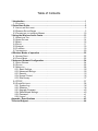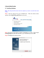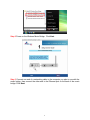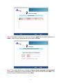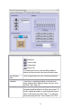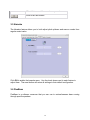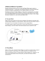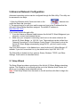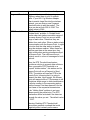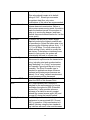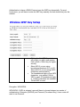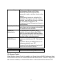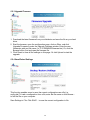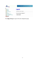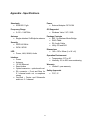
1
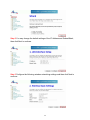
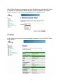
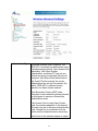
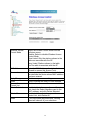
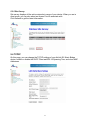
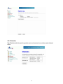
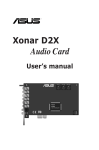
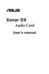
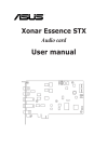
802.11g Wireless Music Bridge Model # AWMB100 User’s Manual Ver. 1A Table of Contents 1 Introduction ................................................................................................................ 1 1.1 FEATURES ................................................................................................................ 1 2 Quick Start Guide ....................................................................................................... 2 2.1 INSTALLING SOFTWARE ............................................................................................. 2 2.2 RUNNING SETUP WIZARD .......................................................................................... 3 2.3 CONNECTING TO THE MUSIC BRIDGE ........................................................................ 10 3 Using the Wireless Audio Center............................................................................ 13 3.1 AUDIO LINK TAB ...................................................................................................... 13 3.2 AUDIO SETTING ...................................................................................................... 14 3.3 MIXER .................................................................................................................... 16 3.4 EFFECT .................................................................................................................. 17 3.5 KARAOKE ............................................................................................................... 19 3.6 FLEXBASS .............................................................................................................. 19 3.7 INFORMATION ......................................................................................................... 20 4 Wireless Modes of operation .................................................................................. 22 4.1 ACCESS POINT ....................................................................................................... 22 4.2 CLIENT MODE ......................................................................................................... 22 5 Advanced Network Configuration........................................................................... 24 5.1 SETUP WIZARD ....................................................................................................... 24 5.2 STATUS .................................................................................................................. 26 5.3 WIRELESS .............................................................................................................. 28 5.3.1 Basic Settings................................................................................................. 28 5.3.2 Advanced Settings ......................................................................................... 29 5.3.3 Security .......................................................................................................... 33 5.3.4 Access Control ............................................................................................... 35 5.3.5 Site Survey ..................................................................................................... 37 5.4 TCP/IP.................................................................................................................. 37 5.5 OTHER SETTINGS ................................................................................................... 38 5.5.1 System Log .................................................................................................... 38 5.5.2 Statistics ......................................................................................................... 39 5.5.3 Upgrade Firmware.......................................................................................... 40 5.5.4 Save/Reload Settings..................................................................................... 40 5.5.5 Password........................................................................................................ 41 5.5.6 Logout ............................................................................................................ 41 Appendix - Specifications .......................................................................................... 43 Technical Support ....................................................................................................... 44 1 Introduction The AirLink101 Music Bridge is a network audio device and wireless Access Point. It allows you to stream all of your audio content from your PC to speakers in your living room or bedroom, in the glory of 5.1 surround sound. As an audio device, AirLink101 Music Bridge is essentially a “wireless sound card”, which plays back all of your computer’s audio. This means that, unlike other wireless media players on the market, AirLink101 Music Bridge allows you to play your copyright-protected music and audio from any program. As a full-featured wireless router, AirLink101 Music Bridge provides WPA, WPA2/802.11i, or WEP encryption, giving you a high level of protection for your data and privacy. The MAC Address filter prevents unauthorized devices from accessing your wireless network, and a web-based utility is provided to allow you to easily make changes to your networking settings. 1.1 Features Audio • • • • Streams all of your audio from your PC to the stereo system in your house using AirLink101 Music Bridge wireless audio technology. Outputs audio to 5.1 channel sound systems, headphones, or digital (S/PDIF) receivers. Streams music to the AirLink101 Music Bridge from any program on your PC. Keeps track of your audio and networking settings with the Wireless Audio Center. Networking • Supports WPA, WPA-2, and WEP encryption. • Can act as a DHCP server or client. • Adjustable Tx power, Tx rate, and SSID broadcast. • Web-based network management tool. • MAC filtering for wireless networking. 1 2 Quick Start Guide 2.1 Installing Software Note: The setup should be done from the computer you want to use with the music bridge. Step 1 Insert the Utility CD into your CD-ROM drive. appears, select Install Utility and Driver from the menu. When the autorun screen Note: If the autorun window does not appear automatically, go to Start -> Run and type D:\Utility\Setup.exe (where D is the letter of your CD-ROM drive) and click OK. Step 2 Click Next at the welcome screen. 2 Step 3 Click Install at the installation screen. 2.2 Running Setup Wizard Step 1 After the software installation finished, the setup wizard will automatically appear. Click on the Click Here to Start. If the wizard does not come up, you can go to Start > All Programs > Airlink101 Wireless Music Bridge > AWMB100 Setup Wizard. 3 Step 2 Power on the Wireless Music Bridge. Click Next. Step 3 Connect one end of a networking cable to the computer you plan to use with the music bridge, then connect the other end to the Ethernet port on the back of the music bridge. Click Next. 4 Step 4 Verify if the LEDs LAN and Power and on. Click Next. Step 5 A list will appear showing your Music Bridge. Select it from the list and click Next. If nothing appears on the list, make sure that the music bridge is connected to your computer and properly powered on. Also make sure that you disable any software firewalls you have installed on your computer. 5 Step 6 The default username for the music bridge is admin and the default password is admin. Enter this into the appropriate boxes and click Enter. Step 7 This screen allows you to change the device name, username, and password. If you want to change any of this information, enter it into the boxes and click Next. You can also leave the default settings and click Next. 6 Step 8 If you are not using the wireless function of the music bridge, click on I only have a wired network and the configuration is complete. You can now connect the music bridge to your router and start playing music. If you plan to use the music bridge wirelessly, go to Step 9. Step 9 Select your network from the list and click connect. 7 Step 10 If your network is encrypted, enter the encryption information at the next screen and click Next. Step 11 The setup is complete. Click on Finish to save the settings. 8 Step 12 You can now disconnect the music bridge from your computer and connect it to your stereo system. The following is a description of the different audio outputs on the Music Bridge. Green – Headphones/Stereo/Front Surround – Plug in your stereo speakers or headphones here. If you are setting up surround sound, use this connection for your front surround speakers. Orange – Center channel/Subwoofer – This connection is used for surround sound. Connect your center channel and subwoofer to this output. Black – Rear Surround – This connection is used for surround sound. Connect your rear surround speakers to this connection. Optical Out – S/PDIF Out – This is an optical digital output for connecting to an external receiver. 9 2.3 Connecting to the Music Bridge Step 1 Double click on the Wireless Audio Center icon in the system tray. If the icon does not appear in the system tray, you can go to Start > All Programs > Airlink101 Wireless Music Bridge > AWMB100 Audio Center. Step 2 Click the Scan Audio Device button. The software will search for and find all Music Bridges on the network. 10 Step 3 Select the music bridge you wish to use from the list and click the Connect button. 11 Step 4 Choose the appropriate Playback Buffer Mode for the type of audio you are playing and click Confirm. You can now play audio on your computer and it will be sent to the music bridge. 12 3 Using the Wireless Audio Center Double-click on the system tray icon on the bottom-right hand corner of your desktop. The Wireless Audio Center will appear for you to configure. 3.1 Audio Link Tab The Audio Link Tab is where you go to connect to your AirLink101 Music Bridge and customize your audio buffer settings (see Playback Buffer Mode below for an explanation). You can also access the Setup Wizard to easily make networking changes to the Music Bridge. Scans and lists all music bridges on the network. Click to connect to the selected device. Click to break the audio connection with your AirLink101 Music Bridge device. Click the hammer icon at the top of the page to change advanced settings. Click the hammer icon under the “Status” bar to access the Web 13 configuration tool Click to open the Setup Wizard. Click to save the current settings from this screen. Click to exit this screen. Playback Buffer Mode Buffer Status Select the length of your audio buffer. A larger audio buffer prevents your signal from “breaking up” when there is lots of traffic on your network. However, it also adds delay between when you perform an action (like playing a song) and when you hear sound. Choose a small buffer setting if you don’t want a long delay and a large buffer if you want to ensure that your audio doesn’t drop out. You can select your own custom buffer length by clicking on the User Defined option and choosing your buffer size. Shows the current buffer usage percentage and history. 3.2 Audio Setting This page enables you to configure your audio output and verify that your speakers are connected properly. 14 Analog Output Here you select what type of system you have hooked up to the AirLink101 Music Bridge. For example, if you’re using headphones, click on the icon. Click on the icon if you’re using a 6-channel (or 5.1) speaker system. S/PDIF Output You can choose either Dolby Digital Live or Digital Audio 48kHz to be output from the digital output jack. Dolby Digital Live: This mode allows you to send 5.1 channel audio data over a single wire. You will need to have a Dolby Digital decoder in the device at the other end of this connection. Note that in this mode, you will not be able to also play audio out of the Music Bridge’s analog speaker jacks. Digital Audio 48KHz: Choose this mode to play 2-channel audio from the digital output jack. Audio System Status Shows which output modes are currently enabled. DSP Mode Click to toggle between the Speaker Shifter and 15 Speaker Test control panes. Click to enable Virtual Speaker Shifter processing. Click to adjust the individual volumes for each channel Click to test the output of each channel. Click to stop an output test. Click to exit this screen. 3.3 Mixer The Mixer allows you to control your volume levels. 16 Volume Control Adjust this knob using your mouse to change the overall volume level. Wave, SW Synth, If you want to change the volume for a specific audio source, you can make separate adjustments to each of these sliders. CD player Click to exit this screen. 3.4 Effect The Effects page lets you spice up your audio by providing a 10-band EQ and environment (reverb) processing. 17 Environment Select the environment you wish to emulate: Bathroom : Concert Hall : Underwater : Music Pub For additional choices, click the More Options button and choose one from the pull-down menu. Environment Size Click to adjust the size of the virtual environment. Equalizer There are 12 equalizer presets to choose from, many optimized for different styles of music, such as Rock, Jazz, Rap, etc.. User Defined You can change the gain settings for each frequency band and save it as your own preset. To do this, tweak the sliders to your liking and enter a name in the empty text field. Click “+” to add your personal setting into the “User Defined” list. Click 18 “-” to delete current the current user preset. Click to exit this screen. 3.5 Karaoke The Karaoke feature allows you to both adjust pitch up/down and remove vocals from regular music tracks. Click ON to enable the karaoke menu. Use the check boxes next to each feature to adjust them. The reset button will return all settings to their default configuration. 3.6 FlexBass FlexBass is a software crossover that you can use to reduce/increase bass coming through specific speakers. 19 3.7 Information This tab displays information about your current 3D audio engine, sound chip, Network audio driver and DirectX version. You can also decide if the audio configuration icon should be shown in the system tray. 20 21 4 Wireless Modes of operation Besides streaming audio around your home, the Music Bridge can be used as a wireless access point. You can also use the Music Bridge as an Ethernet bridge and connect a computer to the Ethernet port for wireless access to your router. By default, the AirLink101 Music Bridge is configured as an Access Point. To change your networking settings quickly and easily, you can go to the Wireless Audio Center and run the Setup Wizard. If you want to configure advanced settings or even change the mode of operation, you can use the web-based utility. 4.1 Access Point When acting as an access point, this device connects all the stations (computers with wireless network adapters) to a wired network. Stations will only have Internet access if the Access Point is connected to the Internet- see the example below. To set the operation mode to Access Point, open the web utility and go to “Wireless J Basic Settings”, and in the “Mode” field click the down arrow to select AP mode. 4.2 Client Mode When in Client mode, AirLink101 Music Bridge can work like a wireless station, where it allows a computer to send data from its wired connection to a wireless network. Refer to the illustration below. Through AirLink101 Music Bridge AP1, Computer 1 can communicate with another Access Point (AP2), and reach the Internet if AP2 is connected to it. 22 To set the operation mode to Client Mode, access the Web configuration tool and go to “Wireless J Basic Settings”, and in the “Mode” field, click the down arrow to select Client mode. Also, under “Network Type”, select “Infrastructure”. 23 5 Advanced Network Configuration Advanced networking options can be configured through the Web Utility. This utility can be accessed in two ways: 1. Open the Wireless Audio Center and click on the hammer icon under the Status bar (see right). 2. The second way is to open your web browser and type in the IP address that the AirLink101 Music Bridge has been assigned. The default IP address is http://192.168.1.210. If you cannot access the web utility: 1. If you don’t have an Ethernet cable between the AirLink101 Music Bridge and your computer, connect one between the two. 2. Make sure your computer’s networking card is set on the same subnet as the AirLink101 Music Bridge, i.e. 192.168.1.xxx. These settings can be verified from “Network Connections” in the Windows Control Panel. If you chose to set up the AirLink101 Music Bridge automatically (using DHCP), you don’t need to worry about this. Start your Web browser. In the Address box, enter the AirLink101 Music Bridge’s IP address. If you don’t know what it is, try the default value, http://192.168.1.210 The Web Utility is divided into four sections: Status, Wireless, TCP/IP, and Other Settings. Each section is described below: 5.1 Setup Wizard The Setup Wizard provides a quick setup of the AirLink101 Music Bridge networking options. This Wizard is not as friendly as the one in the Wireless Audio Center, but allows you to configure more advanced options. Step 1 Click Setup Wizard from the menu on the left and then click Next to begin the Wizard. 24 Step 2 You may change the default settings of the IP Address and Subnet Mask, then click Next to continue. Step 3 Configure the following wireless networking settings and then click Next to continue. 25 Step 4 Select the wireless encryption type from the pull-down menu and click Finish to complete the setup wizard. WPA2 encryption is recommended for the highest level of security, but not all networking equipment is compatible with it. 5.2 Status In this screen, you can see the current settings and status of your AirLink101 Music Bridge device. 26 System Uptime The duration of time the AirLink101 Music Bridge has been servicing the network. Firmware Version The version of the firmware installed on your AirLink101 Music Bridge device. Wireless Configuration Mode There are two modes supported: Access Point and Client Band Shows the wireless band that is being used. SSID The SSID differentiates wireless networks from each other. Therefore, all access points and devices attempting to connect to a network must use the same SSID. It is case-sensitive and must not exceed 32 characters. A device will not be permitted to join the network unless it can provide the unique SSID. The SSID is also referred to as a “network name”. Channel Number The number of channels supported depends on the where in the world you are using the AirLink101 Music Bridge. All stations communicating with the Access Point must use the same channel. Encryption Encryption (Wired Equivalent Privacy) is set to Disabled by default. When WPA, WPA2, or WEP are enabled, data is encrypted before being transmitted onto the network. This prevents data packets from being eavesdropped by attackers and snoopers. By using encryption, there may be a reduction of data throughput on the wireless link. BSSID BSSID displays the ID of the current Basic Service Set (BSS), which uniquely identifies each network. If AirLink101 Music Bridge is in AP mode, this value is its MAC address. Associated Clients Displays the total number of clients associated to this device. You can have up to 64 clients associating to a device at once. TCP/IP Configuration Attain IP Protocol Displays how the AirLink101 Music Bridge obtained its IP address, either through a FixedIP or as a DHCP-client. IP Address Current IP address for this device Subnet Mask Current Subnet mask for this device Default Gateway Default Gateway for this device MAC Address The MAC Address for this device 27 5.3 Wireless 5.3.1 Basic Settings This page includes all major networking parameters. Any parameter changes require the device to reboot for the new settings to take effect. Disable Wireless LAN Interface Band Check this box to disable the Wireless LAN Interface. By doing this, you won’t be able to make wireless connections with this Access Point on its network. In other words, this device will not be visible by any wireless stations. You can choose one of the following modes: ~ 2.4GHz (B): 802.11b supported rate only. ~ 2.4GHz (G): 802.11g supported rate only. ~ 2.4GHz (B+G): 802.11b supported rate and 802.11g supported rate. Mode The default is 2.4GHz (B+G) mode. This Wireless Access Point can support two modes. Access Point 28 Network Type SSID Channel Number Associated Clients Apply Changes Reset and Client. When in Client mode, you can select between Ad-Hoc and Infrastructure types. The SSID differentiates wireless networks from each other. Therefore, all access points and devices attempting to connect to a network must use the same SSID. It is case-sensitive and must not exceed 32 characters. A device will not be permitted to join the network unless it can provide the unique SSID. The SSID is also referred to as a “network name”. Here you can choose to set the channel either manually or automatically. If “Auto” is selected, you can set the channel range to have Wireless Access Point automatically survey and choose the channel with best situation for communication. Click to show a list of wireless clients that are currently connecting to the device. Click to save your new settings. Click to discard the data you have entered. 5.3.2 Advanced Settings It is not recommended that settings in this page be changed unless you are an advanced user that wants the network to meet certain performance objectives. Don’t adjust these settings unless you know exactly what you’re doing. 29 Authentication Type To provide a certain level of security, the IEEE 802.11 standard has defined two types of authentication methods, Open System and Shared Key. With Open System authentication, a wireless PC can join any network and receive messages that are not encrypted. With Shared Key authentication, only those PCs that possess the correct authentication key can join the network. By default, IEEE 802.11 wireless devices operate in an Open System network. Wired Equivalent Privacy (WEP) data encryption is used when the wireless devices are configured to operate in Shared Key authentication mode. If the Access Point is using Open System mode, the wireless adapters on the network will need to be set to the same authentication mode. Shared Key is used when both the sender and the recipient share a secret key. Select Auto for the network adapter to select 30 the Authentication mode automatically. Fragment Threshold Fragmentation is used for improving efficiency when there is a lot of network traffic. If your 802.11g Wireless Adapter often transmits large files into the wireless network, you can enter a new Fragment Threshold value to split the packet. The value can be set from 256 to 2346. The default value is 2346. RTS Threshold RTS Threshold is implemented to prevent the “Hidden Node” problem. A “Hidden Node” results when two stations are within range of the same Access Point, but are not within range of each other. Therefore, they are hidden from each other. When a station starts communication with the Access Point, it might not notice that the other station is already using the wireless medium. When these two stations send data at the same time, they might collide when arriving simultaneously at the Access Point. The collision will most certainly result in a loss of messages for both stations. Thus, the RTS Threshold mechanism provides a solution to prevent data collisions. When you enable RTS Threshold on a suspect “hidden station”, this station and its Access Point will use a Request to Send (RTS). The station will send an RTS to the Access Point, informing that it is going to transmit the data. Upon receipt, the Access Point will respond with a CTS message to tell all stations within range to defer transmission. It will also confirm to the requesting station that the Access Point has reserved it for the time-frame of the requested transmission. If the “Hidden Node” problem is an issue, please specify the packet size. The RTS mechanism will be activated if the data size exceeds the value you set.. The default value is 2347*. Warning: Enabling RTS Threshold will cause some network overhead that could negatively affect network performance 31 instead of providing a remedy. Beacon Interval Data Rate Preamble Type Broadcast SSID IAPP 802.11g Protection *This value should remain at its default setting of 2347. Should you encounter inconsistent data flow, only minor modifications of this value are recommended. Beacon Interval is the amount of time between beacon transmissions. Before a station enters power saving mode, the station needs the beacon interval to know when to wake up to receive the beacon (and learn whether there are buffered frames for it at the access point). By default, the AirLink101 Music Bridge adaptively selects the highest possible rate for transmission. Select the basic rates to be used among the following options: Auto, 1, 2, 5.5, 11or 54 Mbps. For most networks the default setting is Auto, which is usually the best choice. If obstacles or interference are present in Auto mode, the system will automatically fall back to a lower rate. A preamble is a signal used in a wireless environment to synchronize the transmission timing, including start and synchronization frame delimiters. In a "noisy" environment, the Preamble Type should be set to Long Preamble. The Short Preamble type is intended for applications where minimum overhead and maximum performance are desired. If in a "noisy" network environment, the performance will be decreased. Enable this to allow all the wireless stations to detect the SSID of this Access Point. IAPP (Inter-Access Point Protocol) is designed for the enforcement of a unique association throughout a ESS (Extended Service Set). It also provides a secure exchange of a station’s security context between the current access point (AP) and the new AP during the handoff period. The 802.11g standard includes a protection mechanism to ensure mixed 802.11b and 802.11g operation. If this mechanism isn’t enabled, devices using the two standards may interfere with each other and decrease 32 the network’s performance. Apply Change Reset Click this button to save your settings. Click to discard the settings you have entered. 5.3.3 Security Here you can configure the security of your wireless network. If you are using the AirLink101 Music Bridge on an existing network, you will probably have a security scheme already set up, which you should follow here. If you are setting up a new network, you can configure the security however you like. It is suggested that you use encryption to prevent eavesdropping of sensitive data (email, online banking, etc) that may be on your network. Please note, however, that by using encryption, there may be a significant drop in data throughput on the network. Encryption: None This is the default value, and provides no extra level of security Encryption: WEP Warning: There are well-documented flaws with WEP encryption. It is recommended that you use a stronger type of encryption, like WPA or WPA2. WEP (Wired Equivalent Privacy) is a form of encryption that requires a 5 or 10-digit key to be entered. If WEP is selected, you will have to distribute the WEP key either manually (by entering it into each device on the network), or by selecting to Use 802.1x 33 Authentication to have a RADIUS server issue the WEP key dynamically. For most home users, you will have to enter the WEP key manually on each device that joins the network Set WEP key Clicking the Set WEP Keys button will prompt you with a new window. Here, select a 128-bit key for higher security. Select HEX if you are using hexadecimal numbers (0-9, or A-F). Select ASCII if you are using ASCII characters (case-sensitive). Ten hexadecimal digits or five ASCII characters are needed if 64-bit WEP is used; 26 hexadecimal digits or 13 ASCII characters are needed if 128-bit WEP is used. Encryption: WPA/WPA2 WPA/WPA2: If WPA is selected, users will have to choose between two modes of authentication: Enterprise (RADIUS) and Personal (Pre-shared Key). Home users will want to use Personal. 34 Pre-shared Key The pre-shared-key serves as a password for the network. Enter an 8-63 letter password, and ensure that the same password is used on all other clients on the network. There are two formats for setting the Preshared key, Passphrase and Hex. If Hex is selected, users will have to enter a 64-letter key. For easier configuration, the Passphrase (at least 8 characters) format is recommended. Group Key Life Time Enter the number of seconds that will elapse before the group key changes automatically. The default is 86400 seconds. Enable PrePre-authentication provides a way to Authentication establish a Pair-wise Master Key (PMK) before a client associates with the network. The advantage is that the client reduces the time that it takes to join the network. Authentication Port: Enter the RADIUS Server’s port RADIUS Server number provided by your ISP. The default is 1812. IP Address: Enter the RADIUS Server’s IP Address provided by your ISP. Password: Enter the password that the AP shares with the RADIUS Server. Apply Change Reset Click to save your new settings. Press to discard the data you have entered. 5.3.4 Access Control When Wireless Access Control is enabled, only those clients with MAC addresses listed in the access control list can communicate with this Access Point. If the list is empty and this function is enabled, no clients will be able to communicate with this Access Point. 35 Wireless Access Control Mode MAC Address Comment Apply Changes Reset Current Access Control List Delete Selected Delete All Reset Select the Access Control Mode from the pull-down menu. Disable: Select to disable Wireless Access Control Mode. Allow Listed: Only the stations shown in the table can associate with the AP. Deny Listed: Stations shown in the table won’t be able to associate with the AP. Enter the MAC Address of a station that is allowed to access this Access Point. You may enter up to 20 characters to help you describe the device whose MAC address you have entered. Click to save your new settings. Click to discard the data you have entered. Click to show the current access control list. To delete clients from your Access Control List, check the Select checkbox next to the MAC address, and click Delete Selected. To delete all the clients from your Access Control List, click Delete All. If you have made any selections, clicking Reset will clear all of your selections. 36 5.3.5 Site Survey Site survey displays all the active networks in range of your device. When you are in client mode, you can also select an Access Point to associate with. Click Refresh to get the latest information. 5.4 TCP/IP On this page, you can change the TCP/IP settings of your AirLink101 Music Bridge device, enable or disable the DHCP Client and 802.1d Spanning Tree, and clone MAC Addresses. 37 IP Address, Subnet These fields can only be modified when DHCP Mask, Default Client mode is disabled. If you are connecting Gateway to an existing network and are unsure what to enter here, ask the person that set up your network to provide these values for you. DHCP DHCP can be used to automatically configure your network addresses. Select Disable, Client or Server from the pull-down menu. Disable: Don’t use DHCP Client: Automatically obtain a network address. You must have a DHCP server on the network for this to work. Server: The AirLink101 Music Bridge will act as a DHCP server, providing network addresses to other devices on the network. DHCP Client Select the range of network addresses to Range be allocated. Show Client Click to show the current DHCP Client table. DNS Server Enter the IP address of the machine to handle your Domain Name Service requests. 802.1d Spanning Tree Clone MAC Address Apply Change Reset Enabling an 802.1d Spanning Tree will prevent the network from creating infinite loops. Infinite loops can happen in the network when WDS is enabled and there are multiple active paths between stations. You can specify the MAC address of your Access Point, replacing the factory setting. Click this button to save your changes. Click this button to discard your changes. 5.5 Other Settings 5.5.1 System Log This page displays a list of recent events on the network. A network administrator can use the system log to trace problems. 38 5.5.2 Statistics The Statistics table shows the packets sent and received over wireless and ethernet LANs. 39 5.5.3 Upgrade Firmware 1. Download the latest firmware from your distributor and save the file on your hard drive. 2. Start the browser, open the configuration page, click on Other, and click Upgrade Firmware to enter the Upgrade Firmware window. Enter the new firmware’s path and file name (i.e. C:\FIRMWARE\firmware.bin). Or, click the Browse button, find and open the firmware file. 3. Click Reset to clear all the settings on this page. Or click Upload to start the upgrade. 5.5.4 Save/Reload Settings This function enables users to save the current configurations as a file (i.e. config.dat) To load a configuration from a file, enter the file name or click Browse… to find the file on your computer. Save Settings to File: Click SAVE.. to save the current configuration to file. 40 When prompted, select “Save this file to disk”, and enter the file name and the file location. Load Settings From File: Click Browse… if you want to load a pre-saved file, enter the file name with the correct path and then click on Upload. Or click Browse… to select the file. 5.5.5 Password For security reasons, it is recommended that you create a password-protected user account to access the web utility of this Access Point. Leaving the user name and password blank will disable this protection. Remember your user name and password, since you will be asked to enter them every time you access the web utility of this Access Point. User Name New Password Confirm Password Apply Change Reset Enter your user name using up to 30 characters. Your user name can contain letters, numbers and spaces, and is case sensitive. Enter your password using up to 30 characters. Your password can contain letters, numbers and spaces, and is case sensitive. Re-enter the new password for confirmation. Click to save your new settings. Click to discard your changes. 5.5.6 Logout 41 Click Apply Change to logout of the web configuration page. 42 Appendix - Specifications Standards • IEEE 802.11g/b Power • External Adapter: DC 5V/2A Frequency Range • 2.412 ~ 2.497GHz OS Supported • Windows Vista / XP / 2000 Antenna • Single attached 2 dBi dipole antenna Package Contents • 802.11g Wireless Music Bridge • RJ45 Cable • R/L Audio Cable • Utility CD and QIG Security • WEP 64/128 bit • WPA / WPA2 LED • Dimensions • 142 x 130 x 96mm (L x W x H) Power, LAN, WLAN, Audio Interface • Power • Antenna • 10/100 Ethernet • Reset button • Optical connector – optical audio out • R/L connector – Front and Rear for 5.1 channel audio out, or earphone stereo • Cen/Sub – Center and Subwoofer audio out 5.1 channel 43 Operation Environment • Temperature: 0°C to 40° • Humidity: 5% to 95% non-condensing Warranty • Limited 1-year warranty Safety Approvals • FCC, IC Technical Support E-mail: [email protected] Toll Free: 1-888-746-3238 Web site: www.airlink101.com *Theoretical maximum wireless signal rate based on IEEE standard 802.11g specifications. Actual data throughput will vary. Network conditions and environmental factors, including volume of network traffic, building materials and construction, mix of wireless products used, radio frequency interference (e.g., cordless telephones and microwaves) as well as network overhead lower actual data throughput rate. Specifications are subject to change without notice. All products and trademarks are the property of their respective owners. Copyright ©2007 Airlink101® 44