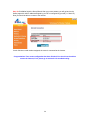
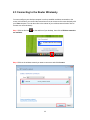
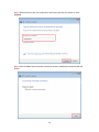
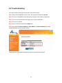
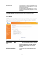
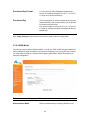
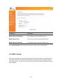
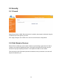
1
Wireless N Green Router
Model # AR675W
User’s Manual
Ver. 1A
Federal Communication Commission
Interference Statement
FCC Part 15
This equipment has been tested and found to comply with the limits for a Class B digital
device, pursuant to Part 15 of FCC Rules. These limits are designed to provide
reasonable protection against harmful interference in a residential installation. This
equipment generates, uses, and can radiate radio frequency energy and, if not installed
and used in accordance with the instructions, may cause harmful interference to radio
communications. However, there is no guarantee that interference will not occur in a
particular installation. If this equipment does cause harmful interference to radio or
television reception, which can be determined by turning the equipment off and on, the
user is encouraged to try to correct the interference by one or more of the following
measures:
1. Reorient or relocate the receiving antenna.
2. Increase the separation between the equipment and receiver.
3. Connect the equipment into an outlet on a circuit different from that to which
the receiver is connected.
4. Consult the dealer or an experienced radio technician for help.
FCC Caution
This equipment must be installed and operated in accordance with provided instructions
and a minimum 20 cm spacing must be provided between computer mounted antenna
and person’s body (excluding extremities of hands, wrist and feet) during wireless
modes of operation.
This device complies with Part 15 of the FCC Rules. Operation is subject to the following
two conditions: (1) this device may not cause harmful interference, and (2) this device
must accept any interference received, including interference that may cause undesired
operation.
Any changes or modifications not expressly approved by the party responsible for
compliance could void the authority to operate equipment.
Federal Communication Commission (FCC) Radiation Exposure Statement
This equipment complies with FCC radiation exposure set forth for an uncontrolled
environment. In order to avoid the possibility of exceeding the FCC radio frequency
exposure limits, human proximity to the antenna shall not be less than 20cm (8 inches)
during normal operation.
The antenna(s) used for this transmitter must not be co-located or operating in
conjunction with any other antenna or transmitter.
The equipment version marketed in US is restricted to usage of the channels 1-11 only.
Table of Contents
CHAPTER 1 INTRODUCTION...........................................................................................................6
1.1 FEATURES ............................................................................................................................................ 6
1.2 PACKAGE CONTENT ............................................................................................................................ 6
1.3 ROUTER INTERFACE ............................................................................................................................ 6
CHAPTER 2 CONNECTING THE ROUTER .....................................................................................9
2.1 BUILDING NETWORK CONNECTION ..................................................................................................... 9
2.2 CONFIGURING THE ROUTER – SETUP WIZARD................................................................................. 11
2.3 CONNECTING TO THE ROUTER WIRELESSLY .................................................................................... 25
2.4 TROUBLESHOOTING ........................................................................................................................... 27
CHAPTER 3 USING WEB CONFIGURATION UTILITY ................................................................ 28
3.1 NETWORK .......................................................................................................................................... 29
3.1.1 WAN.......................................................................................................................................... 29
3.1.2 LAN ........................................................................................................................................... 40
3.1.3 Routing ..................................................................................................................................... 42
3.1.4 DDNS........................................................................................................................................ 43
3.2 WIRELESS .......................................................................................................................................... 45
3.2.1 Basic Settings .......................................................................................................................... 45
3.2.2 Security..................................................................................................................................... 49
3.2.2.1 WEP....................................................................................................................................... 50
3.2.2.2 WPA....................................................................................................................................... 52
3.2.2.3 WPA2..................................................................................................................................... 53
3.2.2.4 WPA-Mixed........................................................................................................................... 54
3.2.2.5 RADIUS Server .................................................................................................................... 55
3.2.3 MAC Control ............................................................................................................................ 56
3.2.4 Advanced Settings .................................................................................................................. 58
3.2.5 Wireless Schedule .................................................................................................................. 59
3.2.6 Security Sync-up ..................................................................................................................... 60
3.3 APPLICATION & GAMING.................................................................................................................... 64
3.3.1 Port Forwarding....................................................................................................................... 64
3.3.2 Port Triggering......................................................................................................................... 65
3.3.3 DMZ........................................................................................................................................... 66
3.3.4 QoS ........................................................................................................................................... 67
3.4 ACCESS RESTRICTIONS .................................................................................................................... 70
3.4.1 Port Filtering............................................................................................................................. 70
3.4.2 IP Filtering ................................................................................................................................ 71
3.4.3 MAC Filtering ........................................................................................................................... 72
3.4.4 URL Filtering ............................................................................................................................ 73
3.5 SECURITY .......................................................................................................................................... 75
3.5.1 Firewall ..................................................................................................................................... 75
3.5.2 DoS (Denial-of-Service) ......................................................................................................... 75
3.5.3 VPN Passthrough.................................................................................................................... 76
3.6 ADMINISTRATION ............................................................................................................................... 78
3.6.1 Time .......................................................................................................................................... 78
3.6.2 Password.................................................................................................................................. 79
3.6.3 Remote Management ............................................................................................................. 80
3.6.4 Firmware Upgrade .................................................................................................................. 80
3.6.5 System Settings ...................................................................................................................... 81
3.6.6 Reboot ...................................................................................................................................... 82
3.6.7 System Log .............................................................................................................................. 82
3.6.8 Statistics ................................................................................................................................... 83
3.6.9 UPnP......................................................................................................................................... 84
3.7 STATUS .............................................................................................................................................. 85
3.7.1 Internet Connection Status .................................................................................................... 85
3.7.2 LAN Status ............................................................................................................................... 85
3.7.3 Wireless Status........................................................................................................................ 86
3.7.4 System Status.......................................................................................................................... 86
TECHNICAL SUPPORT................................................................................................................... 87
Chapter 1 Introduction
Congratulations on your purchase of the AR675W Wireless N Green Router. The Wireless N
Green Router is recommended to be used with AirLink101® Wireless N products to provide the
best performance. The high speed of up to 300Mbps* combined with extended wireless coverage
delivers fast and reliable connections for all of your networking applications.
A full range of security features such as WEP, WPA-PSK, and WPA2-PSK provide the highest
level of wireless network security. The web-based Setup Wizard allows you to set up the router
with an easy-to-use user interface. Green Ethernet technology helps to reduce power usage to
save more energy. Best of all, the AR675W works with 802.11g and 802.11b network devices
which ensures compatibility with your existing wireless products.
1.1 Features
•
•
•
•
•
•
•
•
Industry’s highest wireless data rate with IEEE 802.11n draft specification 2.0
Two 3dBi external antennas for wider coverage and stronger signal strength to eliminate
dead spots
Green Ethernet technology reduces power consumption
64-bit/128-bit WEP encryption, Pre-shared Key (PSK), and Wi-Fi Protected Access
(WPA2 and WPA) support provide full protection for your wireless connection
Stronger signal strength increases the reliability and speed of wireless connections
Great for environments with higher wireless data traffic requirements
Fully backward-compatible with 802.11b/g devices
Works best with AirLink101® Wireless N and 300N Adapters
1.2 Package Content
Before you starting to use this router, please check if there’s anything missing in the package,
and contact your dealer of purchase to claim for missing items:
•
•
•
•
•
Wireless N Green Router
Quick installation guide
Manual CD
A/C power adapter
Ethernet Cable
1.3 Router Interface
Front Panel
6 LED
Light Status
Description
POWER
Solid Green
Router is powered on.
Solid Green
WPS setup is in progress.
Off
Wireless network is switched off.
Flashing
Green
Wireless network is ready and WPS setup is not in
progress.
Solid Green
WAN port is connected.
Off
WAN port is not connected.
Flashing
Green
WAN port is transferring or receiving data.
Solid Green
LAN port is connected.
Off
LAN port is not connected.
Flashing
Green
LAN port is transferring or receiving data.
WLAN
WAN
LNK/ACT
LAN 1-4
LNK/ACT
Back Panel
Antenna A Antenna B
7 Item Name
Description
Antenna A/B
These antennas are 3dBi dipole antennas.
Radio ON/OFF
Switch the button to activate or deactivate the wireless functions.
Reset / Security
Sync
Reset the router to factory default settings (clear all settings) or start
security synchronization function. Press this button and hold for 10
seconds to restore all settings to factory defaults, and press this button 3
seconds to start security synchronization.
1-4
Local Area Network (LAN) ports 1 to 4.
WAN
Wide Area Network (WAN / Internet) port.
Power
Power connector, connects to A/C power adapter.
8 Chapter 2 Connecting the Router
2.1 Building Network Connection
Please follow the instructions below to build the network connection between the Router and your
computers, as well as network devices:
Step 1 Connect your DSL / cable modem to the WAN port of router with an Ethernet cable.
Step 2 Connect all your computers, network devices (network-enabled consumer devices other
than computers, such as game console, or switch / hub) to the LAN ports of the router.
9 Step 3 Connect the A/C power adapter to the electrical outlet, and then connect it to the ‘Power’
socket of the router.
Please check all LEDs on the front panel. ‘POWER’ LED should be steadily on, WAN and LAN
LEDs should be on if the computer / network devices connected to the respective ports of the
router are powered on and correctly connected.
10 2.2 Configuring the Router – Setup Wizard
Step 1 Open the web browser (i.e. Internet Explorer or Mozilla Firefox) and type 192.168.2.1 in
the URL address bar and press Enter.
Step 2 Enter admin for both the user name and password and click OK.
11 Step 3 Click on Setup Wizard.
Step 4 Click Next to start the Setup Wizard.
12 Step 5 Configure the Time Zone Settings of the Router. Click Next.
The Time Zone allows your router to base its time on the settings configured here, this will affect
functions such as Log entries and Firewall settings.
Parameter
Description
Enable NTP client update
Check this box to enable the auto time synchronization
function. The router will set its time based on your
selection.
Automatically Adjust Daylight Saving If the country you live uses daylight saving, please check
this box.
Time Zone Select
You can select your local time zone here. The router will
sync time according to your time zone selection.
NTP server
Select the time server to synchronize with.
Step 6 Click Next to accept Router’s default IP Address or change it to match your existing local
area network settings.
13 The LAN Interface settings allow you to configure the parameters for local area network.
Parameter
Description
IP Address
This is the router’s local port IP address (Your LAN
clients default gateway IP address). The default IP
Address is ‘192.168.2.1’.
Subnet Mask
Specify a Subnet Mask for your LAN segment. The
default subnet mask is ‘255.255.255.0’.
Step 7 Select the Internet Type for your Router.
In this section you have to select one of the five types of connections based on the service
package provided by your ISP.
Menu
Description
Static IP
Your ISP provides a static IP address to you while you subscribe
the service.
DHCP Client
Your ISP automatically assigns an IP address to your modem.
Most Cable service subscribers use this option.
PPPoE
Your ISP requires you to use a Point-to-Point Protocol over
Ethernet (PPPoE) connection. Most DSL service subscribers use
this option.
14 PPTP
Your ISP requires you to use a Point-to-Point Tunneling Protocol
(PPTP) connection.
L2TP
Your ISP requires you to use a Point-to-Point Tunneling Protocol
(L2TP) connection.
Cable Modem
For cable modem, select DHCP Client and click Next. Continue to Step 8.
DSL (DHCP Client or PPPoE)
For DSL users, your Internet type is either DHCP Client or PPPoE. If you are not sure which one
you use, it is suggested to select DHCP Client, and if you cannot connect to the Internet after the
Setup Wizard finished, go through the Setup Wizard again and select PPPoE. Otherwise, you can
call your ISP to confirm which Internet Type you have.
DHCP Setup
Select DHCP Client from the Internet Type drop-down menu and click Next. Continue to Step 8.
PPPoE Setup
Select PPPoE from the Internet Type drop-down menu. Enter your user name and password
provided by your ISP. Click Next.
15 Parameter
Description
User Name
Enter the User Name provided by your ISP for the PPPoE
connection.
Note: Depending on the ISP, you may need to include the
domain name with your username. Example:
[email protected]
Password
Enter the Password provided by your ISP for the PPPoE
connection.
Static IP
Select Static IP if your ISP has given you a specific IP address for you to use. Your ISP should
provide all the information required in this section. Continue to Step 8.
16 Parameters
Description
IP Address
This is the IP address that your ISP has provided for
you.
Subnet Mask
(e.g. 255.255.255.0)
Enter the Subnet Mask provided by your ISP.
Default Gateway IP
This is the ISP’s IP address gateway.
DNS
This is the ISP’s DNS server IP address.
PPTP
Select PPTP if your ISP requires the PPTP protocol to connect you to the Internet. Your ISP
should provide all the information required in this section. Continue to Step 8.
Parameter
Description
Server IP Address
Enter the IP address of the ISP Gateway.
User Name
Enter the User Name provided by your ISP for the PPTP
connection. Sometimes called a Connection ID.
Password
Enter the Password provided by your ISP for the PPTP
connection.
17 L2TP
Select L2TP if your ISP requires the L2TP protocol to connect you to the Internet. Your ISP
should provide all the information required in this section. Continue to Step 8.
Parameter
Description
Server IP Address
Enter the IP address of the ISP Gateway.
User Name
Enter the User Name provided by your ISP for the L2TP
connection. Sometimes it is called a Connection ID.
Password
Enter the Password provided by your ISP for the L2TP
connection.
Step 8 Keep the default SSID (wireless network name) or change it to a desired name, so you
can always recognize your wireless network with it. Click Next.
18 Menu
Description
Mode
Please select the radio band from one of the following options.
2.4GHz(B): 2.4GHz band, only allows 802.11b wireless network
client to connect to this router (maximum transfer rate 11Mbps).
2.4 GHz (N): 2.4GHz band, only allows 802.11n wireless network
client to connect to this router (maximum transfer rate 150Mbps).
2.4 GHz (B+G):2.4GHz band, only allows 802.11b and 802.11g
wireless network client to connect to this router (maximum
transfer rate 11Mbps for 802.11b clients, and maximum 54Mbps
for 802.11g clients).
2.4 GHz (G): 2.4GHz band, only allows 802.11g wireless
network client to connect to this router (maximum transfer rate
54Mbps).
2.4 GHz (B+G+N): 2.4GHz band, allows 802.11b, 802.11g, and
802.11n wireless network client to connect this router (maximum
transfer rate 11Mbps for 802.11b clients, maximum 54Mbps for
802.11g clients, and maximum 150Mbps for 802.11n clients).
SSID
This is the name of the wireless network. You can type any
alphanumerical characters here, maximum 32 characters. SSID
is used to identify your own wireless router from others when
there are other wireless routers in the same area. The default
SSID is ‘airlink101’; it’s recommended to change it to a name
that you can identify, such as myhome, office_room1, etc.
19 Channel Width
Set channel width of wireless radio. Do not modify default value
if you don’t know what it is, default setting is ‘40 MHz’.
Control SideBand
Select the Upper or Lower band for your Control Sideband.
While Upper band is selected, the channels you can select are
from channel 5 to channel 11. While Lower band is selected, the
channels you can select are from channel 1 to channel 7.
802.11n needs to use five continuous channels for high-speed
transmission.
Channel Number
Select a channel from the dropdown list of ‘Channel Number’ for
broadcasting. You can choose any channel number you want to
use, and almost all wireless clients can locate the channel you’re
using automatically without any problem. However, it’s still useful
to remember the channel number you use, some wireless client
supports manual channel number selecting, and this would help
in certain scenario when there is some radio communication
problem.
Step 9 Select a desired Security Mode from the drop-down menu.
WPA2(AES) is the most secured encryption mode for general users. WEP is the most common
encryption but the least secured. It is recommended to use WPA2 (AES) for your wireless
security if all wireless devices on your network can support this mode.
WEP
20 Parameters
Description
Key Length
You can select the WEP key length for encryption, 64-bit
or 128-bit. Larger WEP key length will provide higher
level of security, but the throughput will be lower.
Key Format
You may select ASCII Characters (alphanumeric format)
or Hexadecimal digits (in the "A-F", "a-f" and "0-9" range)
to be the WEP Key.
Key Setting
The WEP key is used to encrypt data transmitted in the
wireless network. Fill the text box by following the rules
below.
64-bit WEP: input 10-digit Hex values (in the "A-F", "a-f"
and "0-9" range) or 5-digit ASCII character as the
encryption keys.
128-bit WEP: input 26-digit Hex values (in the "A-F", "af" and "0-9" range) or 13-digit ASCII characters as the
encryption keys.
Click on Finished to save and activate all the settings. Now, you can start to use the router as
your internet gateway.
21 WPA(TKIP)
Wi-Fi Protected Access (WPA) is an advanced security standard. You can use a pre-shared key
to authenticate wireless stations and encrypt data during communication. It uses TKIP to change
the encryption key frequently.
Parameters
Description
Pre-shared Key Format
You may select to select Passphrase (alphanumeric
format) or Hexadecimal Digits (in the “A-F”, “a-f” and “09” range) to be the Pre-shared Key. For example:
Passphrase: iamguest
Hexadecimal Digits: 12345abcde
Pre-shared Key
The Pre-shared key is used to authenticate and encrypt
data transmitted in the wireless network. Fill the text box
by following the rules below.
Hex: input 8~64bit Hex key (in the “A-F”, “a-f” and “0-9”
range) for the pre-shared key.
Passphrase: input 8~63 characters for the pre-shared
key.
Clicking on OK to save and activate all the settings. Now, you can start to use the router as your
internet gateway.
22 WPA2(AES) / WPA2-Mixed
Select WPA2 (AES) for Security Mode, and enter a Pre-Shared Key between 8 to 63 characters
(alphanumeric, case sensitive).
Wi-Fi Protected Access 2(WPA2) is an advanced security standard. You can use a pre-shared
key to authenticate wireless stations and encrypt data during communication. It uses AES to
change the encryption key frequently. WPA2-mixed supports both WPA2 and WPA. It is a good
choice when some wireless devices on your network support WPA only.
Parameters
Description
Pre-shared Key Format
You may select Passphrase (alphanumeric format) or
Hexadecimal digits (in the “A-F”, “a-f” and “0-9” range) to
be the Pre-shared Key.
Pre-shared Key
The Pre-shared key is used to authenticate and encrypt
data transmitted in the wireless network. Fill the text box
by following the rules below.
Hex: input 64-digit Hex values (in the “A-F”, “a-f” and “09” range) or at least 8 character pass phrase as the preshared keys.
Click on Finished to save and activate all the settings. Now, you can start to use the router as
your internet gateway.
Note: It is suggested to write down the security settings (Security Mode and Key) you
configured for the Router on a piece of paper and keep it in a safe place.
23 Step 10 Click OK to finish the Setup Wizard. After your router restarts, you will go back to the
Status page with valid IP address assigned by you ISP or configured by yourself (i.e. Static IP).
Now you should be able to connect to the Internet.
If each field has a valid number assigned, the router is connected to the Internet.
Congratulations! Your router configuration has been finished. You should now be able to
access the Internet; if not, please go to section 2.4 for troubleshooting.
24 2.3 Connecting to the Router Wirelessly
You must configure your wireless computer in order to establish a wireless connection to the
router. In this section, you can find the instructions of how to connect to the router wirelessly with
your Vista computer. You can also refer to the manual of your wireless network card of how to
connect to a router wirelessly.
Step 1 Click on this icon
are available.
on the task bar of your desktop, then click on Wireless networks
Step 2 Click on the wireless network you want to connect to and click Connect.
25 Step 3 Enter the Security key you configured for the Router (see Step 8 in Section 2). Click
Connect.
Step 4 Click on Close. Now the wireless connection has been established successfully with the
Router.
26 2.4 Troubleshooting
If you have trouble connecting to the Internet, try the following steps.
Step 1 Power off the Cable/DSL modem, router, and computer and wait for 5 minutes.
Step 2 Turn on the Cable/DSL modem and wait for the lights on the modem to settle down.
Step 3 Turn on the router and wait for the lights on the router to settle down.
Step 4 Turn on the computer.
Step 5 Log in to the router and select the Status tab.
Step 6 Verify that the Internet IP Address, Subnet Mask, and Default Gateway have valid
numbers assigned to them (instead of all 0’s).
If each field has a valid number assigned, the router is connected to the Internet.
27 Chapter 3 Using Web Configuration
Utility
The Web Configuration Utility contains advanced features that allow you to configure the router to
meet your network’s needs such as: Multiple AP, Access Control, QoS (Quality of Service), Port
Forwarding (Virtual Server) and other functions.
If you have already configured the Setup Wizard, you do NOT need to configure any other thing
here for you to start using the Internet.
Below is a general description of what advance functions are available for this broadband router.
Menu
Description
3.0 Setup Wizard
This quick setup wizard can guide you through the basic settings
of this Router. Please see instructions in Chapter 2.2.
3.1 Network
This section allows you to configure the Internet settings with
your ISP, the settings for your local area network (LAN), such as
enable/disable the DHCP server, Dynamic DNS information, and
routing rules.
3.2 Wireless
This section allows you to setup the Router’s SSID, security key,
scheduling, etc.
3.3 Application & Gaming This section allows you to configure router’s setting for your
special applications or gaming requirements.
3.4 Access Restrictions
This section allows you to set up the access control rules, such
as MAC filtering, URL filtering to prevent the LAN users from
accessing certain type of website.
3.5 Security
This Firewall section allows you to configure Hacker Prevention
and DMZ.
3.6 Administration
The section allows you to specify a time zone, change the
system password, save/reload the router configuration, upgrade
firmware and so on.
3.7 Status
You can see Router’s status in this section.
28 3.1 Network
3.1.1 WAN
Use the WAN Settings screen to change your Internet connection type. The WAN Settings screen
allows to specify the type of WAN port connect you want to establish with your ISP. The WAN
settings offer the following selections for the router’s WAN port, Static IP Address, DHCP Client,
PPPoE, PPTP, L2TP and DDNS. Please choose one type and complete the detail settings below.
A) Static IP
Select Static IP address if your ISP has given you a specific IP address for you to use. Your ISP
should provide all the information required in this section.
29 Parameters
Description
IP Address
This is the IP address that your ISP has given you.
Subnet Mask
Enter the Subnet Mask provided by your ISP. (e.g.
255.255.255.0)
Default Gateway
This is the IP address of ISP’s gateway.
MTU Size
MTU (Maximum Transmission Unit) determine the maximum size
of each packet in any transmission within the network. Please
specify the MTU range from 1400 to 1500 bytes. Please input
the MTU value of your network connection here. If you don’t
know, you can use default value.
DNS 1~3
Please input the IP address of DNS server provided by your
service provider.
Clone MAC Address
For some applications, you may need to designate a specific
MAC address for the router. Please enter the MAC address here.
If you are connecting the router to a computer, you can simply
press ‘Clone Mac’ button to fill the MAC address field with the
MAC address of your computer.
30 Enable IGMP Proxy
Check this box if you want to enable the router as IGMP proxy to
implement multicast routing. Keep default if you don’t know what
it is.
Enable FTP ALG on Port
If you have built up a FTP server in your network, you can
enable this function to let the FTP traffics correctly pass though
the NAT gateway of the router. Enter the port number of your
FTP server. Keep default if you don’t know what it is.
TTL
For some special applications, you might need to change the
TTL value for the packets routing to your router. Please select
‘TTL Standard’, ‘TTL+1’, ‘TTL=1’ or ‘User Defined” to define a
value. If you don’t know what it is / not sure if you need it, it’s
safe to set this option to ‘TTL Standard’. Keep default if you don’t
know what it is.
Click <Apply Changes> at the bottom of the screen to save the above configurations.
B) DHCP Client
Choose this option if your ISP will automatically assign you an IP address. Some ISP’s may also
require that you fill in additional information such as Host Name, Domain Name and MAC
address.
31 Parameters
Description
Host Name
Please enter the host name, this is optional, and only required if
your service provider asks you to do so.
MTU Size
MTU (Maximum Transmission Unit) determine the maximum size
of each packet in any transmission within the network. Please
specify the MTU range from 1400 to 1492 bytes. Please input
the MTU value of your network connection here. If you don’t
know, you can use default value.
Obtain DNS Automatically The ISP requires you to obtain a DNS by DHCP server before
you connecting to the internet.
Set DNS Manually
If your ISP gives you a static DNS server address to be used to
connect to the internet, please select this option.
DNS 1~3
Please input the IP address of DNS server provided by your
service provider.
Clone MAC Address
For some applications, you may need to designate a specific
MAC address for the router. Please enter the MAC address here.
If you are connecting the router to a computer, you can simply
press ‘Clone Mac’ button to fill the MAC address field with the
MAC address of your computer.
32 Enable IGMP Proxy
Check this box if you want to enable the router as IGMP proxy to
implement multicast routing. Keep default if you don’t know what
it is.
Enable FTP ALG on Port
If you have built up a FTP server in your network, you can
enable this function to let the FTP traffics correctly pass though
the NAT gateway of the router. Enter the port number of your
FTP server. Keep default if you don’t know what it is.
TTL
For some special applications, you might need to change the
TTL value for the packets routing to your router. Please select
‘TTL Standard’, ‘TTL+1’, ‘TTL=1’ or ‘User Defined” to define a
value. If you don’t know what it is / not sure if you need it, it’s
safe to set this option to ‘TTL Standard’. Keep default if you don’t
know what it is.
Click <Apply Changes> at the bottom of the screen to save the above configurations.
C) PPPoE (PPP over Ethernet)
Select PPPoE if your ISP requires the PPPoE protocol to connect you to the Internet. Your ISP
should provide all the information required in this section.
33 Parameters
Description
User Name
Please input user name assigned by your Internet service
provider here.
Password
Please input the password assigned by your Internet service
provider here.
Service Name
Please give a name to this Internet service, this is optional
Connection Type
Please select the connection type of Internet connection you
wish to use. There are 3 options: “Continuous” - keep internet
connection alive, do not disconnect, “connect on Demand“ only connects to Internet when there’s a connect attempt, and
“Manual” - only connects to Internet when ‘Connect’ button on
this page is pressed, and disconnects when ‘Disconnect button
is pressed.
Idle Time
Please input idle time out. Specify the time to shutdown internet
connection after no internet activity is detected after a while. This
option is only available when connection type is ‘Connect on
Demand’.
MTU Size
MTU (Maximum Transmission Unit) determine the maximum size
of each packet in any transmission within the network. Please
specify the MTU range from 1360 to 1492 bytes. Please input
the MTU value of your network connection here. If you don’t
know, you can use default value.
Obtain DNS Automatically The ISP requires you to obtain a DNS by DHCP server before
you connecting to the internet.
Set DNS Manually
If your ISP gives you a static DNS server to be used to connect
to the internet, please select this option.
DNS 1~3
Please input the IP address of DNS server provided by your
service provider.
Clone MAC Address
For some applications, you may need to designate a specific
MAC address for the router. Please enter the MAC address here.
If you are connecting the router to a computer, you can simply
press ‘Clone Mac’ button to fill the MAC address field with the
MAC address of your computer.
34 Enable IGMP Proxy
Check this box if you want to enable the router as IGMP proxy to
implement multicast routing. Keep default if you don’t know what
it is.
Enable FTP ALG on Port
If you have built up a FTP server in your network, you can
enable this function to let the FTP traffics correctly pass though
the NAT gateway of the router. Enter the port number of your
FTP server. Keep default if you don’t know what it is.
TTL
For some special applications, you might need to change the
TTL value for the packets routing to your router. Please select
‘TTL Standard’, ‘TTL+1’, ‘TTL=1’ or ‘User Defined” to define a
value. If you don’t know what it is / not sure if you need it, it’s
safe to set this option to ‘TTL Standard’. Keep default if you don’t
know what it is.
Click <Apply Changes> at the bottom of the screen to save the above configurations.
D) PPTP
Select PPTP if your ISP requires the PPTP protocol to connect you to the Internet. Your ISP
should provide all the information required in this section.
35 Parameters
Description
Attain IP Automatically
Select this option if your ISP will assign IP Address to your router
directly. Please contact your ISP if you don’t know what you
should select.
Set IP Address
This is the IP address that your ISP has given you.
Subnet Mask
Enter the Subnet Mask provided by your ISP. (e.g.
255.255.255.0)
Default Gateway
This is the IP address of ISP’s gateway.
Server IP Address
Please input the IP address of PPTP gateway assigned by your
Internet service provider here.
User Name
Please input user name assigned by your Internet service
provider here.
Password
Please input the password assigned by your Internet service
provider here.
Connection Type
Please select the connection type of Internet connection you
wish to use. There are 3 options: “Continuous” - keep internet
connection alive, do not disconnect, “connect on Demand“ only connects to Internet when there’s a connect attempt, and
36 “Manual” - only connects to Internet when ‘Connect’ button on
this page is pressed, and disconnects when ‘Disconnect button
is pressed.
Idle Time
Please input idle time out. Specify the time to shutdown internet
connection after no internet activity is detected after a while. This
option is only available when connection type is ‘Connect on
Demand’.
MTU Size
MTU (Maximum Transmission Unit) determine the maximum size
of each packet in any transmission within the network. Please
specify the MTU range from 1400 to 1460 bytes. Please input
the MTU value of your network connection here. If you don’t
know, you can use default value.
Request MPPE Encryption MPPE (Microsoft Point-to-Point Encryption) is a method of
encrypting data across PPTP virtual private network
connections. Check this box if it is needed for your virtual
private network links.
Request MPPC Encryption MPPC (Microsoft Point-to-Point Compression) which
compresses data across virtual private network links. Check this
box if it is needed.
Obtain DNS Automatically The ISP requires you to obtain a DNS by DHCP server before
you connecting to the internet.
Set DNS Manually
If your ISP gives you a static DNS server to be used to connect
to the internet, please select this option.
DNS 1~3
Please input the IP address of DNS server provided by your
service provider.
Clone MAC Address
For some applications, you may need to designate a specific
MAC address for the router. Please enter the MAC address here.
If you are connecting the router to a computer, you can simply
press ‘Clone Mac’ button to fill the MAC address field with the
MAC address of your computer.
Enable IGMP Proxy
Check this box if you want to enable the router as IGMP proxy to
implement multicast routing. Keep default if you don’t know what
it is.
Enable FTP ALG on Port
If you have built up a FTP server in your network, you can
enable this function to let the FTP traffics correctly pass though
37 the NAT gateway of the router. Enter the port number of your
FTP server. Keep default if you don’t know what it is.
TTL
For some special applications, you might need to change the
TTL value for the packets routing to your router. Please select
‘TTL Standard’, ‘TTL+1’, ‘TTL=1’ or ‘User Defined” to define a
value. If you don’t know what it is / not sure if you need it, it’s
safe to set this option to ‘TTL Standard’. Keep default if you don’t
know what it is.
Click <Apply Changes> at the bottom of the screen to save the above configurations.
E) L2TP
Select L2TP if your ISP requires the L2TP protocol to connect you to the Internet. Your ISP
should provide all the information required in this section.
Parameters
Description
38 Attain IP Automatically
Select this option if your ISP will assign IP Address to your router
directly. Please contact your ISP if you don’t know what you
should select.
Set IP Manually
This is the IP address that your ISP has given you.
IP Address
This is the IP address that your ISP has given you.
Subnet Mask
Enter the Subnet Mask provided by your ISP. (e.g.
255.255.255.0)
Default Gateway
This is the IP address of ISP’s gateway.
Server IP Address
Please input the IP address of L2TP gateway assigned by your
Internet service provider here.
User Name
Please input user name assigned by your Internet service
provider here.
Password
Please input the password assigned by your Internet service
provider here.
Connection Type
Please select the connection type of Internet connection you
wish to use. There are 3 options: “Continuous” - keep internet
connection alive, do not disconnect, “connect on Demand“ only connects to Internet when there’s a connect attempt, and
“Manual” - only connects to Internet when ‘Connect’ button on
this page is pressed, and disconnects when ‘Disconnect button
is pressed.
Idle Time
Please input idle time out. Specify the time to shutdown internet
connection after no internet activity is detected after a while. This
option is only available when connection type is ‘Connect on
Demand’.
MTU Size
MTU (Maximum Transmission Unit) determine the maximum size
of each packet in any transmission within the network. Please
specify the MTU range from 1400 to 1460 bytes. Please input
the MTU value of your network connection here. If you don’t
know, you can use default value.
Obtain DNS Automatically The ISP requires you to obtain a DNS by DHCP server before
you connecting to the internet.
Set DNS Manually
If your ISP gives you a static DNS server to be used to connect
to the internet, please select this option.
39 DNS 1~3
Please input the IP address of DNS server provided by your
service provider.
Clone MAC Address
For some applications, you may need to designate a specific
MAC address for the router. Please enter the MAC address here.
If you are connecting the router to a computer, you can simply
press ‘Clone Mac’ button to fill the MAC address field with the
MAC address of your computer.
Enable IGMP Proxy
Check this box if you want to enable the router as IGMP proxy to
implement multicast routing. Keep default if you don’t know what
it is.
Enable FTP ALG on Port
If you have built up a FTP server in your network, you can
enable this function to let the FTP traffics correctly pass though
the NAT gateway of the router. Enter the port number of your
FTP server. Keep default if you don’t know what it is.
TTL
For some special applications, you might need to change the
TTL value for the packets routing to your router. Please select
‘TTL Standard’, ‘TTL+1’, ‘TTL=1’ or ‘User Defined” to define a
value. If you don’t know what it is / not sure if you need it, it’s
safe to set this option to ‘TTL Standard’. Keep default if you don’t
know what it is.
Click <Apply Changes> at the bottom of the screen to save the above configurations.
3.1.2 LAN
This page allows you to specify an IP address for your router as well as a subnet mask for your
LAN segment.
40 Parameters
IP address
Subnet Mask
Default
192.168.2.1
This is the router’s LAN IP address (Your LAN
clients default gateway IP address).
255.255.255.0
Specify a Subnet Mask for your LAN segment.
Default Gateway
DHCP
Description
Specify the default gateway for LAN segment.
Server
DHCP Client Range
By selecting the DHCP server, the router will
automatically give your LAN clients an IP
address. If the DHCP server is not enabled then
you’ll have to manually set your LAN client’s IP
addresses; make sure the LAN Client is in the
same subnet as this broadband router if you
want the router to be your LAN client’s default
gateway.
You can configure a particular IP address range
for your DHCP server to assign IP addresses to
your LAN Clients.
Note: By default the IP range is from: Start IP
192.168.2.100 to End IP 192.168.2.200. If you
want your PC to have a static/fixed IP address
then you’ll have to choose an IP address outside
this IP address range.
802.1d Spanning Tree Disabled
If 802.1d Spanning Tree function is enabled, this
router will use the spanning tree protocol to
prevent from network loop happened in the LAN
ports.
41 Static DHCP
Specify the Static DHCP Addresses for your
LAN clients.
Domain Name
Enter the domain name of your LAN interface if
there is one.
Click <Apply Changes> at the bottom of the screen to save the above configurations.
3.1.3 Routing
You can turn off the NAT function of your router by enabling the Static Routing and let the router
forward packets by your routing policy.
Parameter
Description
Enable Static Routing
Destination LAN IP
Enable/disable the NAT function
Enter the IP Address of the destination LAN.
Subnet Mask
Enter the Subnet Mask of the destination LAN.
Default Gateway
This is the gateway IP Address where packets are sent.
Input the gateway IP Address.
Static Routes
From the table, you can check each Static Routing
setting.
Delete Selected
If you want to delete a setting, check the ‘select’ box of
the setting you want to delete, then click ‘Delete
42 Selected’ button. (You can select more than one
setting).
Delete All
If you want to delete all settings listed here, please click
‘Delete All’ button.
Reset
You can also click ‘Reset’ button to unselect all.
Click <Apply Changes> at the bottom of the screen to save the above configurations.
3.1.4 DDNS
DDNS allows you to map the static domain name to a dynamic IP address. You must get an
account, password and your static domain name from the DDNS service providers. This router
supports DynDNS, and TZO.
Parameters
Enable DDNS
Default
Disable
Description
Enable/Disable the DDNS function of this router.
Service Provider
Select a DDNS service provider.
Domain name
Your static domain name that use DDNS.
User Name/Email
The account that your DDNS service provider
assigned to you.
43 Password/Key
The password you set for the DDNS service
account above.
Click <Apply Changes> at the bottom of the screen to save the above configurations.
44 3.2 Wireless
3.2.1 Basic Settings
You can set parameters that are used for the wireless stations to connect to this router. The
parameters include SSID, Channel Number and etc.
Parameters
Default
Description
Disable Wireless
LAN Interface
Check this box to disable wireless LAN.
Mode
Please select the radio band from one of the
following options.
2.4GHz(B): 2.4GHz band, only allows 802.11b
wireless network client to connect this router
(maximum transfer rate 11Mbps*).
2.4 GHz (N): 2.4GHz band, only allows 802.11n
wireless network client to connect this router
(maximum transfer rate 300Mbps*).
2.4 GHz (B+G):2.4GHz band, only allows
802.11b and 802.11g wireless network client to
connect this router (maximum transfer rate
11Mbps for 802.11b clients, and maximum
54Mbps for 802.11g clients*).
45 2.4 GHz (G): 2.4GHz band, only allows 802.11g
wireless network client to connect this router
(maximum transfer rate 54Mbps*).
2.4 GHz (B+G+N): 2.4GHz band, allows
802.11b, 802.11g, and 802.11n wireless network
client to connect this router (maximum transfer
rate 11Mbps for 802.11b clients, maximum
54Mbps for 802.11g clients, and maximum
300Mbps for 802.11n clients*).
Multiple APs
SSID
This access point supports Multiple APs function.
Please go to section 3.2.1.1 below for more
information.
airlink101
This is the name of your wireless network. You
can type any alphanumerical characters here,
maximum 32 characters. SSID is used to identify
your own wireless router from others when there
are other wireless routers in the same area. It’s
recommended to change default SSID value to
the one which is meaningful to you, like
myhome, office_room1, etc.
Channel Width
Set channel width of wireless radio. Do not
modify default value if you don’t know what it is,
default setting is ‘40 MHz’.
Control SideBand
Select the Upper or Lower band for your Control
Sideband. While Upper band is selected, the
channel number you can select is from channel
5 to channel 11. While Lower band is selected,
the channel number you can select is from
channel 1 to channel 7.
Channel Number
Please select a channel from the dropdown list
of ‘Channel Number’ for broadcasting. You can
choose any channel number you want to use,
and almost all wireless clients can locate the
channel you’re using automatically without any
problem. However, it’s still useful to remember
the channel number you use, some wireless
client supports manual channel number select,
and this would help in certain scenario when
there is some radio communication problem.
Broadcast SSID
Decide if the wireless router will broadcast its
own SSID or not. You can hide the SSID of your
46 wireless router (set the option to ‘Disable’), so
only people those who know the SSID of your
wireless router can get connected.
WMM
The short of Wi-Fi MultiMedia, it will enhance the
data transfer performance of multimedia
contents when they’re being transferred over
wireless network. If you don’t know what it is /
not sure if you need it, it’s safe to set this option
to ‘Enable’.
Data Rate
Set the wireless data transfer rate to a certain
value. Since most of wireless devices will
negotiate with each other and pick a proper data
transfer rate automatically, it’s not necessary to
change this value unless you know what will
happen after modification.
Show Active Clients
Click “Show Active Clients” button, then an
“Active Wireless Client Table” will pop up. You
can see the status of all active wireless clients
that are connecting to the Router.
Click <Apply Changes> at the bottom of the screen to save the above configurations.
3.2.1.1 Multiple APs
The AR675W supports Multiple APs function. With different SSID names, you can separate to
four wireless networks with different wireless security, WMM, access control and etc.
47 Parameters
Default
Description
Enable
Check this box if you want to enable multiple
access points.
Band
Please select the radio band from one of the
following options.
2.4GHz(B): 2.4GHz band, only allows 802.11b
wireless network client to connect this router
(maximum transfer rate 11Mbps).
2.4 GHz (N): 2.4GHz band, only allows 802.11n
wireless network client to connect this router
(maximum transfer rate 150Mbps).
2.4 GHz (B+G):2.4GHz band, only allows
802.11b and 802.11g wireless network client to
connect this router (maximum transfer rate
11Mbps for 802.11b clients, and maximum
54Mbps for 802.11g clients).
2.4 GHz (G): 2.4GHz band, only allows 802.11g
wireless network client to connect this router
(maximum transfer rate 54Mbps).
2.4 GHz (B+G+N): 2.4GHz band, allows
802.11b, 802.11g, and 802.11n wireless network
client to connect this router (maximum transfer
rate 11Mbps for 802.11b clients, maximum
54Mbps for 802.11g clients, and maximum
150Mbps for 802.11n clients).
SSID
This is the name of wireless router. You can
type any alphanumerical characters here,
maximum 32 characters. SSID is used to identify
your own wireless router from others when there
are other wireless routers in the same area.
Default SSID is ‘default-VAP0/1/2/3’, it’s
recommended to change default SSID value to
the one which is meaningful to you, like
myhome, office_room1, etc.
Data Rate
Set the wireless data transfer rate to a certain
value. Since most of wireless devices will
negotiate with each other and pick a proper data
transfer rate automatically, it’s not necessary to
48 change this value unless you know what will
happen after modification.
Broadcast SSID
Decide if the wireless router will broadcast its
own SSID or not. You can hide the SSID of your
wireless router (set the option to ‘Disable’), so
only people those who know the SSID of your
wireless router can get connected.
WMM
The short of Wi-Fi MultiMedia, it will enhance the
data transfer performance of multimedia
contents when they’re being transferred over
wireless network. If you don’t know what it is /
not sure if you need it, it’s safe to set this option
to ‘Enable’.
Access
If you want to limit stations connect to the
specific access point with the right to access
Internet only, please select ‘WAN’. By default, it
is not enabled the access control.
Active Client List
Click “Show” button, then an “Active Wireless
Client Table” will pop up. You can see the status
of all active wireless stations that are connecting
to the access point.
Click <Apply Changes> at the bottom of the screen to save the above configurations.
3.2.2 Security
The AR675W provides complete wireless LAN security functions, include WEP, IEEE 802.11x,
IEEE 802.11x with WEP, WPA with pre-shared key and WPA with RADIUS. With these security
functions, you can prevent your wireless LAN from illegal access. Please make sure your wireless
clients use the same security function. You can choose different security modes for each SSID (if
you have enabled Multiple APs).
49 Parameters
Default
Select SSID
Description
If you have configured multiple access
points, please select the access point you want
to configure.
Security Mode
You can choose no encryption, WEP, WPA,
WPA2 or WPA2 mixed mode for security.
802.1x Authentication
IEEE 802.1x is an authentication protocol. Every
user must use a valid account to login to this
Access Point before accessing the wireless
LAN. The authentication is processed by a
RADIUS server. Check this box to authenticates
user by IEEE 802.1x.
Click <Apply Changes> at the bottom of the screen to save the above configurations. You can
now configure other advance sections or start using the router (with the advance settings in
place)
3.2.2.1 WEP
When you select 64-bit or128-bit WEP key, you have to enter WEP keys to encrypt data. You can
generate the key by yourself and enter it.
50 Parameters
Description
Authentication
There are two authentication types: "Open System" and
"Shared Key". When you select "Open System", wireless
stations can associate with this wireless router without
WEP encryption. When you select "Shared Key", you
should also setup WEP key in the "Security" page and
wireless stations should use WEP encryption in the
authentication phase to associate with this wireless
router. If you select "Auto", the wireless client can
associate with this wireless router by using any one of
these two authentication types.
Key Length
You can select the WEP key length for encryption, 64-bit
or 128-bit. Larger WEP key length will provide higher
level of security, but the throughput will be lower.
Key Format
You may select to select ASCII Characters
(alphanumeric format) or Hexadecimal Digits (in the "AF", "a-f" and "0-9" range) to be the WEP Key.
Encryption Key
The WEP key are used to encrypt data transmitted in the
wireless network. Fill the text box by following the rules
below.
64-bit WEP: input 10-digit Hex values (in the "A-F", "a-f"
and "0-9" range) or 5-digit ASCII character as the
encryption keys.
51 128-bit WEP: input 26-digit Hex values (in the "A-F", "af" and "0-9" range) or 13-digit ASCII characters as the
encryption keys.
Click <Apply Changes> at the bottom of the screen to save the above configurations.
3.2.2.2 WPA
Wi-Fi Protected Access (WPA) is an advanced security standard. You can use a pre-shared key
to authenticate wireless stations and encrypt data during communication. It uses TKIP to change
the encryption key frequently. So the encryption key is not easy to be broken by hackers. This
can improve security very much.
Parameters
Description
Authentication Mode
WPA can authenticate by Enterprise (RADIUS) or by
Personal (Pre-Shared key). If you enable ‘Enterprise
(RADIUS)’, please go to section 3.2.2.5 for more
information.
WPA Encryption Mode
You can choose TKIP or AES for encryption method.
Pre-shared Key Format
You may select to select Passphrase (alphanumeric
format) or Hexadecimal Digits (in the “A-F”, “a-f” and “09” range) to be the Pre-shared Key. For example:
52 Pre-shared Key
The Pre-shared key is used to authenticate and encrypt
data transmitted in the wireless network. Fill the text box
by following the rules below.
Hex: input 64-digit Hex values (in the “A-F”, “a-f” and “09” range) or at least 8 character pass phrase as the preshared keys.
Click <Apply Changes> at the bottom of the screen to save the above configurations.
3.2.2.3 WPA2
Wi-Fi Protected Access 2 (WPA2) is an advanced security standard. You can use a pre-shared
key to authenticate wireless stations and encrypt data during communication. It uses CCMP
(AES) to change the encryption key frequently, so the encryption key is difficult to be broken
which highly improve the wireless security.
Parameters
Authentication
Description
Mode
WPA can authenticate by Enterprise (RADIUS)
or by
Personal (Pre-Shared key). If you enable ‘Enterprise
(RADIUS)’, please go to section 3.2.2.5 for more
information.
WPA2 Encryption Mode
You can choose TKIP or AES for WPA2 encryption
method.
53 Pre-shared Key Format
You may select to select Passphrase (alphanumeric
format) or Hexadecimal Digits (in the “A-F”, “a-f” and “09” range) to be the Pre-shared Key.
Pre-shared Key
The Pre-shared key is used to authenticate and encrypt
data transmitted in the wireless network. Fill the text box
by following the rules below.
Hex: input 64-digit Hex values (in the “A-F”, “a-f” and “09” range) or at least 8 character pass phrase as the preshared keys.
Click <Apply Changes> at the bottom of the screen to save the above configurations.
3.2.2.4 WPA-Mixed
This security mode combines WPA and WPA2. You can use TKIP or AES encryption method for
either mode which highly increases the security and complexity of your encryption key. However,
you must make sure that your wireless clients support either WPA or WPA2 mode before you
make this configuration.
Parameters
Description
Authentication Mode
WPA can authenticate by Enterprise (RADIUS) or by
54 Personal (Pre-Shared key). If you enable ‘Enterprise
(RADIUS)’, please go to section 3.2.2.5 for more
information.
WPA Encryption Mode
You can choose TKIP or AES for WPA key method.
WPA2 Encryption Mode
You can choose TKIP or AES for WPA2 key method.
Pre-shared Key Format
You may select to select Passphrase (alphanumeric
format) or Hexadecimal Digits (in the “A-F”, “a-f” and “09” range) to be the Pre-shared Key.
Pre-shared Key
The Pre-shared key is used to authenticate and encrypt
data transmitted in the wireless network. Fill the text box
by following the rules below.
Hex: input 64-digit Hex values (in the “A-F”, “a-f” and “09” range) or at least 8 character pass phrase as the preshared keys.
Click <Apply Changes> at the bottom of the screen to save the above configurations.
3.2.2.5 RADIUS Server
IEEE 802.1x is an authentication protocol. Every user must use a valid account to login to this
wireless router before accessing the wireless LAN. The authentication is processed by a RADIUS
server. This mode only authenticates user by IEEE 802.1x, but it does not encryption the data
during communication. If there is a RADIUS server in you environment, please enable this
function. Check this box and another sub-menu will appear.
55 Parameters
Description
Radius Server IP Address
The IP address of external RADIUS server.
Radius Server Port
The service port of the external RADIUS server.
Radius Server Password
The password used by external RADIUS server.
Click <Apply Changes> at the bottom of the screen to save the above configurations.
3.2.3 MAC Control
This function will help you to prevent unauthorized users from connecting to your wireless router.
Only those wireless devices with the MAC addresses you specified here are allowed to access
your wireless router. You can use this function with other security measures described in previous
section together.
56 Parameters
Description
Wireless Access Control Mode
Enable/Disable wireless access control. You can
choose ‘Allow Listed’ if you allow the MAC
Addresses listed in the following table to connect
to the router; choose ‘Deny Listed’ if you deny
the MAC Addressed listed in the following table
to connect to the router.
MAC Address
Input the MAC address of your wireless devices
here, format ‘aa:bb:cc:dd:ee:ff’.
Comment
You can input any text here as the comment of
this MAC address, like ‘ROOM 2A Computer’ or
anything.
Current Access Control List
From the table, you can check the access
control settings.
Delete Selected
If you want to delete a specific MAC address
entry, check the ‘select’ box of the MAC address
you want to delete, then click ‘Delete Selected’
button. (You can select more than one MAC
addresses).
Delete All
If you want to delete all MAC addresses listed
here, please click ‘Delete All’ button.
Reset
You can also click ‘Reset’ button to unselect all.
Click <Apply Changes> at the bottom of the screen to save the above configurations.
57 3.2.4 Advanced Settings
You can set advanced wireless LAN parameters of this router. The parameters include
Authentication Type, Fragment Threshold, RTS Threshold, Beacon Interval, Preamble Type, etc.
It is suggested not to change these parameters unless you know what effect the changes will
have on this router.
Parameters
Default
Description
Fragment Threshold
"Fragment Threshold" specifies the maximum
size of packet during the fragmentation of data
to be transmitted. If you set this value too low, it
will result in bad performance.
RTS Threshold
When the packet size is smaller than the RTS
threshold, the wireless router will not use the
RTS/CTS mechanism to send this packet.
Beacon Interval
The interval of time that this wireless router
broadcast a beacon. Beacon is used to
synchronize the wireless network.
58 Preamble Type
The “Long Preamble” can provide better
wireless LAN compatibility while the “Short
Preamble” can provide better wireless LAN
performance.
IAPP
If you enable “IAPP”, it will allow wireless station
roaming between IAPP enabled access points
within the same wireless LAN.
Protection
This is also called CTS Protection. It is
recommended to enable the protection
mechanism. This mechanism can decrease the
rate of data collision between 802.11b and
802.11g/802.11n wireless stations. When the
protection mode is enabled, the throughput of
the AP will be a little lower due to many of frame
traffic should be transmitted.
Aggregation
This function is used to join multiple data
packets for transmission as a single unit to
increase network efficiency.
Short GI
The 802.11n draft specifies two guard intervals:
400ns (short) and 800ns (long). Support of the 400ns
GI is optional for transmit and receive. Enable this
function will increase network efficiency.
WLAN Partition
Enable this function and all the wireless clients cannot
access to each other.
RF Output Power
You can set the output power of wireless radio.
Unless you’re using this wireless router in a
really big space, you may not have to set output
power to 100%. This will enhance security
(malicious / unknown users in distance will
not be able to reach your wireless router).
Click <Apply Changes> at the bottom of the screen to save the above configurations.
3.2.5 Wireless Schedule
This page allows you to set up the wireless schedule rules. You can designate to enable wireless
interface by time or day.
59 Parameters
Description
Enable Wireless Schedule
Check this box to enable wireless schedule.
Days
Select to enable the wireless access point every
day or some other weekdays.
Time
Designate a period of hours in a day to enable
the wireless access point.
Click <Apply Changes> at the bottom of the screen to save the above configurations. You can
now configure other advance sections or start using the router (with the advance settings in
place)
3.2.6 Security Sync-up
The AR675W Airlink101 Wireless N Router has a Security Button built-in which allows you to
connect your wireless computer with the router easily and safely. Your wireless adapter must
support this feature as well. If not, you will need to set up the wireless security manually and you
can skip this section.
60 Uncheck this box Please make sure this feature is enabled on the Router (see the screenshot above). In the
instructions below, we are going to use the Airlink101 WLAN Monitor utility comes with the
AWLL6077, Airlink101 Wireless N adapter as an example.
Step 1 Go to the computer with Airlink101 Wireless N adapter, AWLL6077 connected.
Step 2 Push and hold the Security button on the Adapter until you see the following window pops
up on the computer monitor.
61 Step 3 Push the Security button the Router for 3 seconds. The WLAN LED will stay solid green
instead of blinking.
Step 4 The Router will now start the handshake with the wireless adapter which will take about 2
minutes. When you see the window similar to the one below, the connection has been
established.
62 63 3.3 Application & Gaming
3.3.1 Port Forwarding
The Port Forwarding allows you to re-direct a particular range of service port numbers (from the
Internet/WAN Ports) to a particular LAN IP address. It helps you to host some servers behind the
router NAT firewall.
Parameter
Description
Enable Port Forwarding
Enable Port Forwarding
IP Address
This is the private IP of the server behind the NAT
firewall. Note: You need to give your LAN PC clients a
fixed/static IP address for Port Forwarding to work
properly.
Protocol
This is the protocol type to be forwarded. You can
choose to forward “TCP” or “UDP” packets only or
select “both” to forward both “TCP” and “UDP” packets.
Port Range
The range of ports to be forward to the private IP.
Comment
The description of this setting.
Current Port Forwarding Table
From the table, you can check each Port forwarding
setting.
Delete Selected
If you want to delete a setting, check the ‘select’ box of
the setting you want to delete, then click ‘Delete
Selected’ button. (You can select more than one setting).
64 Delete All
If you want to delete all settings listed here, please click
‘Delete All’ button.
Reset
You can also click ‘Reset’ button to unselect all.
Click <Apply Changes> at the bottom of the screen to save the above configurations.
3.3.2 Port Triggering
Port triggering allows the router to keep track of outgoing data for specific port numbers.
The router remembers which computer sends out what data, so that when the requested
data returns through the router, the data is sent back to the proper computer by way of
IP address and port mapping rules.
Parameter
Description
Enable Port Triggering
Check to enable Port Triggering, or uncheck to disable.
IP Address
This is the private IP of the computer/server behind the
NAT firewall. Note: You need to give your PC a
fixed/static IP address for Port Triggering to work
properly.
Computer Name
This is the computer that you need to enable the port
triggering function. Select a PC from here if you do not
65 know its IP address and click on the << button to add
the IP address to the left blank. If you do not see any
computer after you click on the drop-down menu, select
the option “Refresh” and you will be given a list of
computers that are connected to your network.
TCP/UDP Port to Open
This is the TCP/UDP ports you want to trigger. Type in
a range of TCP/UDP ports to be triggered. For instance,
“5000-5300” or “9091, 9093-9100”, depending on your
special application’s requirement.
Comment
The description of this setting.
Popular Application
This list includes many popular applications you may be
using. Select the application you want to use and click
on the Add button next to it; you will see the proper port
numbers added to the “TCP/UDP Port to Open” blank.
Add (in red box)
Click on Add button in the red box to save the trigger
rule you set into the Trigger-Port Table.
Current Trigger-Port Table
From the table, you can select each Port triggering
setting by checking the “Select” checkbox.
Delete Selected
If you want to delete a setting, check the ‘select’ box of
the setting you want to delete, then click ‘Delete
Selected’ button. (You can select more than one
setting).
Delete All
If you want to delete all settings listed here, please click
‘Delete All’ button.
Reset
You can also click ‘Reset’ button to unselect all.
Click <Apply> at the bottom of the screen to save the above configurations.
3.3.3 DMZ
If you have a local client PC that cannot run an Internet application (e.g. Games) properly from
behind the NAT firewall, then you can open the client up to unrestricted two-way Internet access
66 by defining a DMZ Host. The DMZ function allows you to re-direct all packets going to your WAN
port IP address to a particular IP address in your LAN.
Parameters
Description
Enable DMZ
Enable/disable DMZ.
DMZ Host IP Address
Input the IP address of a particular host in your LAN that will
receive all the packets originally going to the WAN port/Public IP
address above
Note: You need to give your LAN PC clients a fixed/static IP
address for DMZ to work properly.
Click <Apply Changes> at the bottom of the screen to save the above configurations. You can
now configure other advance sections or start using the router (with the advance settings in
place)
3.3.4 QoS
Quality of service provides an efficient way for computers on the network to share the internet
bandwidth with a promised quality of internet service. Without QoS, all computers and devices on
the network will compete with each other to get internet bandwidth, and some applications which
require guaranteed bandwidth (like video streaming and network telephone) will be affected,
therefore an unpleasing result will occur, like the interruption of video / audio transfer.
With this function, you can limit the maximum bandwidth or give a guaranteed bandwidth for a
specific computer, to avoid said unpleasing result from happening.
67 Parameter
Description
Enable QoS
Check this box to enable QoS, and uncheck this box to
disable QoS.
Automatic Uplink Speed
Check this box to enable automatic uplink speed.
Manual Uplink Speed (Kbps)
You can set the limit of uplink speed in Kbps. To
disable uplink bandwidth limitation, input ‘0’ here.
Local IP Address
Input the IP Address of your computer to configure the
QoS rule.
Mode
Select to guarantee a minimum or maximum bandwidth
to the IP Address you designate.
Bandwidth (Kbps)
Input the bandwidth in Kbps.
Comment
Please input any text to describe this QoS rule.
Current QoS Rules Table
From the table, you can check each QoS rule setting.
Delete Selected
If you want to delete a setting, check the ‘select’ box of
the setting you want to delete, then click ‘Delete
Selected’ button. (You can select more than one setting).
68 Delete All
If you want to delete all settings listed here, please click
‘Delete All’ button.
Reset
You can also click ‘Reset’ button to unselect all.
Click <Apply Changes> at the bottom of the screen to save the above configurations.
69 3.4 Access Restrictions
The AR675W Wireless N Green Router provides extensive ways to restrict local users to access
Internet.
3.4.1 Port Filtering
If you want to restrict users from accessing certain Internet applications/services (e.g. Internet
websites, email, FTP etc.) by port numbers, then this is the place to set that configuration. Entries
in this table are used to restrict certain types of data packets from your local network to Internet
through the Router. Port filters can be helpful in securing or restricting your local network.
Parameters
Description
Enable Port Filtering
Check this box to enable the port filtering function.
Port Range
The range of ports to be blocked.
Protocol
Choose ‘TCP’ or ‘UDP’ or ‘Both’ protocols for port
filtering.
Comment
You can input any text here as the comment of this
settings.
Current Filter Table
From the table, you can check each port filter setting.
Delete Selected
If you want to delete a specific setting, check the ‘select’
box of the setting you want to delete, then click ‘Delete
Selected’ button. (You can select more than one setting).
Delete All
If you want to delete all settings listed here, please click
‘Delete All’ button.
70 Reset
You can also click ‘Reset’ button to unselect all.
Click <Apply Changes> at the bottom of the screen to save the above configurations.
3.4.2 IP Filtering
If you want to restrict users from accessing certain Internet applications/services (e.g. Internet
websites, email, FTP etc.) by their IP addresses, then you can set up the filtering rules here.
Entries in this table are restricted to use certain type of connections from the router. IP filters can
be helpful in securing or restricting your local network.
Parameters
Description
Enable IP Filtering
Check this box to enable the IP filtering function.
Local IP Address
Input the IP Address you want to filter.
Protocol
Choose ‘TCP’ or ‘UDP’ or ‘Both’ protocols for port
filtering.
Comment
You can input any text here as the comment of this
settings.
Current Filter Table
From the table, you can check each IP filter setting.
Delete Selected
If you want to delete a specific setting, check the ‘select’
box of the setting you want to delete, then click ‘Delete
Selected’ button. (You can select more than one setting).
71 Delete All
If you want to delete all settings listed here, please click
‘Delete All’ button.
Reset
You can also click ‘Reset’ button to unselect all.
Click <Apply Changes> at the bottom of the screen to save the above configurations.
3.4.3 MAC Filtering
If you want to restrict users from accessing certain Internet applications/services (e.g. Internet
websites, email, FTP etc.) by their MAC addresses, then you can set up the filtering rules here.
Entries in this table are used to restrict certain types of data packets from your local network to
Internet through the Router. MAC filter can be helpful in securing or restricting your local network.
Parameters
Description
Enable MAC Filtering
Check this box to enable the MAC filtering function.
MAC Address
Input the MAC address of the devices you want to filter,
format ‘aa:bb:cc:dd:ee:ff’.
Comment
You can input any text here as the comment of this MAC
address, like ‘ROOM 2A Computer’.
Current Filter Table
From the table, you can check each MAC Address filter
setting.
72 Delete Selected
If you want to delete a specific MAC address entry,
check the ‘select’ box of the MAC address you want to
delete, then click ‘Delete Selected’ button. (You can
select more than one MAC addresses).
Delete All
If you want to delete all MAC addresses listed here,
please click ‘Delete All’ button.
Reset
You can also click ‘Reset’ button to unselect all.
Click <Apply Changes> at the bottom of the screen to save the above configurations.
3.4.4 URL Filtering
You can block access to some Websites or web contents from local PCs by entering a full URL
address or just keyword of the Web site. This filter can help parents to manage the Internet usage
for their children (i.e. Parental Control).
Parameter
Description
Enable URL Filtering
Enable/Disable URL Blocking.
URL Address
You can enter the full URL address of a website or any
keyword of certain web contents you want to block.
Current Filter Table
From the table, you can check each URL filter setting.
73 Delete Selected
If you want to delete a setting, check the ‘select’ box of
the setting you want to delete, then click ‘Delete
Selected’ button. (You can select more than one setting).
Delete All
If you want to delete all settings listed here, please click
‘Delete All’ button.
Reset
You can also click ‘Reset’ button to unselect all.
Click <Apply Changes> at the bottom of the screen to save the above configurations.
74 3.5 Security
3.5.1 Firewall
Enable Ping Access on WAN: When this function is enabled, other people are allowed to ping the
IP address of the router given by your ISP.
Click <Apply Changes> at the bottom of the screen to save the above configurations.
3.5.2 DoS (Denial-of-Service)
Denial of Service (DoS) is a common attack measure, by transmitting a great amount of data or
request to your Internet IP address and server, the Internet connection will become very slow,
and server may stop responding because it is not capable to handle too much traffics.
This router has a built-in DoS attack prevention mechanism; when you activate it, the router will
stop the DoS attack for you.
75 Click <Apply Changes> at the bottom of the screen to save the above configurations.
3.5.3 VPN Passthrough
Parameter
Description
76 Enable IPsec pass through
On VPN connection
Check this box and the router will enable IPsec packets
pass through the router for VPN connection.
Enable PPTP pass through
On VPN connection
Check this box and the router will enable PPTP packets
pass through the router for VPN connection
Enable L2TP pass through
On VPN connection
Check this box and the router will enable L2TP packets
pass through the router for VPN connection.
Click <Apply Changes> at the bottom of the screen to save the above configurations.
77 3.6 Administration
The Administration page allows you to specify a time zone, to change the system password and
to specify a remote management port, to upgrade firmware, to save/reload configuration settings,
to enable system log, to view the statistics information, and to enable/disable UPnP for the
Router.
3.6.1 Time
Parameter
Description
Current Time
Set the current time.
Time Zone Select
Select the time zone of the country you are currently in.
The router will set its time based on your selection.
Enable NTP client update
Check the box to enable router to update time from NTP
server.
Automatically Adjust
Daylight Saving
If the country you live uses daylight saving, please check
this box.
NTP Server
Select one preset time server or manual input a server
IP.
Click <Apply Changes> at the bottom of the screen to save the above configurations.
78 3.6.2 Password
You can change the password required to log into the Router's web configuration utility. The
default user name and password are “admin”. It is suggested to change the administrator’s
default password as soon as you start to use the Router, and store it in a safe place. The
password can contain 0 to 12 alphanumeric characters, and are case sensitive.
Parameters
Description
User Name
Change your login user name.
New Password
Enter your new password
Confirmed Password
Enter your new password again for verification purposes
Note: If you forget your password, you’ll have to reset the router
to the factory default (user name and password are both ‘admin’)
with the reset button on the back of the router.
Click <Apply Changes> at the bottom of the screen to save the above configurations.
79 3.6.3 Remote Management
Enable the remote management so an authorized user can configure the Router from a remote
site. You can specify a port for the remote management.
Click <Apply Changes> at the bottom of the screen to save the above configurations.
3.6.4 Firmware Upgrade
This page allows you to upgrade the router’s firmware
80 To upgrade the firmware for the Router, you need to download the firmware file to your local hard
disk, and click on Browse to select it, then click Upload to start the upgrade process. (You may
have to wait a few minutes for the upgrade to complete).
3.6.5 System Settings
The System Settings screen allows you to save (Backup) the router’s current configuration
setting. Saving the configuration settings provides an added protection and convenience should
problems occur with the router and you have to reset to factory default. When you save the
configuration settings (Backup) you can re-load the saved settings into the router through the
Restore function. If extreme problems occur you can use the Restore Settings to Default
selection, this will set all configurations to its original default settings (e.g. when you first
purchased the router).
Parameters
Description
Save Settings to File
Click Save button to save the Broadband router current
configuration to a file named "config.bin" on your PC.
Load Settings from File
Click Browse button to search the file you have saved before and
click Upload button to restore the saved configuration to the
Broadband router.
Restore Settings to Default
Click Reset button if you want to force the Broadband router to
perform a power reset and restore the original factory settings.
81 3.6.6 Reboot
3.6.7 System Log
View the operation log of the system.
Parameters
Description
Enable Log
Check this box to enable the logging system.
82 System all
This page shows the current system log of the Broadband router.
It displays any event occurred after system start up.
At the bottom of the page, the system log can be cleared with
Clear button or it can be refreshed by Refresh button to get the
most updated situation. When the system is powered down, the
system log will disappear if not saved to a local file.
Wireless
By select this options, you can check wireless log.
DoS
By select this options, you can check DoS log.
Enable Remote Log
If you want to send all log information to remote server, please
check this box to enable this function and fill the server IP
Address in the “Log Server IP Address” field.
Log Server IP Address
Input the server IP address where you want to save the logs.
Click <Apply Changes> at the bottom of the screen to save the above configurations.
3.6.8 Statistics
View the statistics of packets sent and received on WAN, LAN and Wireless LAN.
83 Parameters
Description
Statistics
Shows the counters of packets sent and received on WAN, LAN
and Wireless LAN.
3.6.9 UPnP
Check the box to enable UPnP feature here. After you enable the UPnP feature, all client
systems that support UPnP, like Windows XP, can discover this router automatically.
Click <Apply Changes> at the bottom of the screen to save the above configurations.
84 3.7 Status
The Status section allows you to monitor the current status of your router. You can use the Status
page to monitor: the Internet, LAN connection, Wireless status, and the current firmware version
of the Router.
3.7.1 Internet Connection Status
3.7.2 LAN Status
85 3.7.3 Wireless Status
3.7.4 System Status
86 Technical Support
E-mail: [email protected]
Toll Free: 1-888-746-3238
Website: www.airlink101.com
*Theoretical maximum wireless signal rate derived from IEEE standard 802.11g and draft 802.11n specifications. Actual
data throughput will vary. Network conditions and environmental factors, including volume of network traffic, building
materials and construction, mix of wireless products used, radio frequency interference (e.g., cordless telephones and
microwaves) as well as network overhead lower actual data throughput rate. This product is based on IEEE draft 802.11n
specification and is not guaranteed to be compatible with future versions of IEEE 802.11n specification. Compatibility with
draft 802.11n devices from other manufactures is not guaranteed. Specifications are subject to change without notice.
Photo of product may not reflect actual content. All products and trademarks are the property of their respective owners.
Copyright ©2009 Airlink101®
87