1
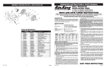
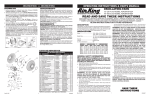
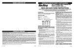
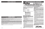
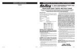
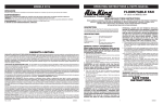
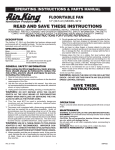
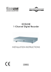
OPERATING INSTRUCTIONS & PARTS MANUAL
MODELO 4C630N/9012N y 4C631P/9016P
29
1
WALL MOUNTED
OSCILLATING FANS
2
4
3
32
12" (30.4 cm) MODEL 4C630N/9012N
16" (40.6 cm) MODEL 4C631P/9016P
31
23
22
5
33
18
30
6
21
10
25
20
22
4 24
19
18
34
READ AND SAVE THESE INSTRUCTIONS
35
READ CAREFULLY BEFORE ATTEMPTING TO ASSEMBLE, INSTALL, OPERATE OR MAINTAIN THE PRODUCT
DESCRIBED. PROTECT YOURSELF AND OTHERS BY OBSERVING ALL SAFETY INFORMATION. FAILURE TO
COMPLY WITH INSTRUCTIONS COULD RESULT IN PERSONAL INJURY AND/OR PROPERTY DAMAGE!
8
9
27
36
11
12
RETAIN INSTRUCTIONS FOR FUTURE REFERENCE.
7
AirKing 12" (30.4 cm) and 16" (40.6 cm) Wall Mounted Oscillating
Fans offer pull cord speed control, variable oscillation, a permanent
split capacitor motor and OSHA-complying front steel mesh grill with
a 6 ft (1.8m) 18/3 cord set.
28
37
26
7
17
35
4
16
13
14
Rev. P 3/05
LISTA DE REPUESTOS
No.
1
2
3
4
Parte No. for Modelo
4C630M/9012M
4C631N/9016N
2010119
2010119
02030062GL
02030066GL
2010665
2010665
02090040
02090040
5
6
7
8
9
10
02090140
2010276
02010548A
02010163
02010162B
2010165
02090140
2010276
02010548A
02010163
02010162B
2010165
11
12
2010252
02090051
2010252
02090051
13
14
15
16
17
18
19
20
21
22
23
24
2010131
02050009AWFPC
02090744
2090539
02090272
02090045A
2010552
2060202
2060316
2090003
2090529
02055047
2010131
02050009AWFPC
02090744
2090539
02090272
02090045A
2010552
2060202
2060316
2090003
2090529
02055047
25
26
27
28
29
30
31
32
33
34
35
36
37
2010512P
02090521A
02090518
02090033
2010661
07091657
02090060
2011212
2010359
2010008
2010058
02096217
02010381A
2010512P
02090521A
02090518
02090033
2010661
07091657
02090060
2011200M
2010359
2011013
2010059
02096214I
02010381A
Ref.
15
circumstances must the grounding prong be cut off the plug.
Where a two-prong wall receptacle is encountered, it must be
replaced with a properly grounded three-prong receptacle installed in accordance with the National Electrical Code (NEC)
and all applicable local codes and ordinances. This work must
be done only by a qualified electrician, using copper wire only.
DESCRIPTION
8
Descripción
Cant.
Botón de Oscilación
1
Motor
1
Cubierta del Motor (Frontal)
1
Tornillo de la Cubierta Tipo B
#7 x 7/16" PTH
3
Tornillo de Enlace
2
Enlace
1
Boton Tipo H.C.
2
Cubierta de la Pieza del Cuello 1
Placa de Trinquete
1
Bola de Oscilación Doble con
Resorte
1
Pieza del Cuello
1
Tornillo Phillips de Cabeza
Reforzada #7 x .390 PTH
1
Botón del Interruptor (Rotatorio) 1
Cordón Eléctrico
1
Tire Cuerda
1
Casquillo del Cordón Accionador 1
Pata de Caucho
2
Tornillo Phillips Tipo 25 #8 x 3/4" 6
Tapa del Interruptor
1
Placa Tracera para Colgar
1
Placa de Montaje
1
Tornillo Phillips #8 x 1-1/4"
2
Tuerca para Alambre
2
Interruptor con Cordón
Accionador
1
Cuerpo
1
Eje de Elevación
1
Resorte de Elevación
1
Tuerca Hexagonal
1
Cubierta del Motor (Trasera)
1
Vástago del Motor
1
Tornillo #7 x .8 PPH ZP Tipo B 2
Rejilla Plástica Trasera
1
Tuerca de la Rejilla
1
Paletas
1
Tapa
1
Rejilla Frontal
1
Ornamento de la Rejilla
1
2084060A
SPECIFICATIONS
WARNING: USE OF A THREE-PRONG TO TWO-PRONG
Motor ................................. 120V, 60 Hz (12", 30.4 cm)
120V, 60 Hz (16", 40.6 cm)
Blade diameter .................. 12" ( 30.4 cm) Model 4C630N/9012N
16" (40.6 cm) Model 4C631P/9016P
Speeds .............................. 3
Control .............................. Pull Cord
Air flow distribution ........... 90°
Approvals .......................... UL Listed. Close mesh Fan Guard
meets OSHA requirements.
ADAPTER IS NOT RECOMMENDED. IMPROPER CONNECTION MAY CREATE THE RISK OF ELECTROCUTION.
USE OF SUCH ADAPTERS IS NOT PERMITTED IN CANADA.
WARNING: THIS PLUG IS A SAFETY FEATURE. TO
REDUCE THE RISK OF FIRE, ELECTRIC SHOCK AND
PERSONAL INJURY, DO NOT REMOVE, REPLACE,
REPAIR OR TAMPER WITH THE ORIGINALLY SUPPLIED
PLUG. IF THE FAN DOES NOT FUNCTION PROPERLY, IT
MAY BE DUE TO THE SAFETY DEVICE INCORPORATED
IN THIS PLUG. RETURN TO AN AUTHORIZED SERVICE
CENTER OR CALL 800-233-0268, MONDAY - FRIDAY,
BETWEEN 8:30 AM AND 4:00 PM EST. IF THE PLUG
WARNING LABEL IS MISSING OR DAMAGED, CALL THE
TOLL FREE NUMBER FOR A REPLACEMENT LABEL.
MODEL
SPEED
4C630N/9012N
4C631P/9016P
HIGH
MED
LOW
HIGH
930
0.44
1450
0.40
39
45
780
0.37
1300
0.30
35
41
620
0.29
1090
0.27
32
36
1710
0.80
1545
0.71
77
53
CFM
M3/s
RPM
Amps
Watts
dBA
MED
1500
0.71
1394
0.54
65
49
LOW
1330
0.63
1244
0.48
57
44
8. Where possible, avoid the use of extension cords. If they must be
used, minimize the risk of overheating by ensuring that they are
UL listed. Never use a single extension cord to operate more
than one Fan.
9. Do not operate any Fan with a damaged cord or plug or after the
Fan malfunctions, has been dropped or damaged in any manner.
Return Fan to authorized service facility for examination, electrical
or mechanical adjustment or repair.
10.Do not insert or allow fingers or foreign objects to enter any
ventilation or exhaust opening as it may cause an electric shock
or fire, or damage the Fan. Do not block or tamper with the Fan
in any manner while it is in operation.
11.Always place the Fan on a stable, flat, level surface when
operating, to avoid the chance of the Fan overturning. Locate the
Power Cord so the Fan or other objects are not resting on it. Do
not run Power Cord under carpeting. Do not cover Power Cord
with throw rugs, runners, or the like. Arrange Power Cord away
from room traffic and where it will not be tripped over.
12.This Fan is not intended for use in wet or damp locations.
Never locate a Fan where it may fall into a bathtub or other
water container.
13. Do not use Fan outdoors.
GENERAL SAFETY INFORMATION
When using electrical appliances, basic precautions should always be followed to reduce the
risk of fire, electric shock and injury to person,
including the following:
1. Read all instructions before using Fan.
2. Make certain that the power source conforms to the electrical
requirements of the Fan.
3. Use this Fan only as described in this manual. Any other use not
recommended by the manufacturer may cause fire, electrical
shock, or injury to persons.
4. Unplug power cord before installing, servicing, or moving the Fan.
WARNING: DO NOT DEPEND UPON THE ON-OFF
SWITCH AS THE SOLE MEANS OF DISCONNECTING
POWER WHEN INSTALLING OR SERVICING THE FAN.
ALWAYS UNPLUG THE POWER CORD.
5. This Fan must NOT be used in potentially dangerous
locations such as flammable, explosive, chemical-laden
or wet atmospheres.
6. DO NOT use Fan in or near a window. Rain may create an
electrical hazard.
7. The power cord is equipped with a three-prong grounded plug
that must be inserted into a matching receptacle. Under no
Rev. P 3/05
WARNING: REDUCE THE RISK OF FIRE OR ELECTRIC
SHOCK – DO NOT USE THIS FAN WITH ANY SOLID STATE
SPEED CONTROL DEVICES.
SAVE THESE
INSTRUCTIONS
1
2084060A
MODEL 4C630N/9012N and 4C631P/9016P
MODELO 4C630N/9012N y 4C631P/9016P
GARANTÍA LIMITADA
Pin
GARANTÍA LIMITADA DE TRES AÑOS DE AIRKING. AirKing garantiza el producto al usuarlo original, contra defectos de mano
de obra o materiales en condiciones de uso normales. El motor está garantizado por tres años y todas las demás partes por un
año, a partir de Ia fecha de compra. Toda pieza qua AirKing determine que está defectuosa en material o mano de obra y sea
enviada a un centro de serviclo autorizado, designado por AirKing, con los costos de envío prepagados, será, como remedio
exclusivo, reparada o reemplazada a opción de AirKing. Para procedimientos de reclamación de garantía, véase el párrafo de
RÁPIDA DISPOSICIÓN a continuación. Esta garantía limitada otorga a los compradores derechos legales específicos que
varían de estado a estado.
Groove
Motor
Detail 2
LIMITACIÓN DE RESPONSABILI DAD. En Ia medida que lo permitan las leyes aplicables, AirKing renuncia expresamente a
toda responsabilidad por daños y perjuicios indirectos. La responsabilidad de AirKing en todo caso estará limitada al precio de
compra y no habrá de exceder de éste.
DENEGACIÓN DE GARANTÍA. AirKing ha realizado un esmerado esfuerzo por ilustrar y describir de manera precisa los prod uctos
que aparecen en el presente material impreso; sin embargo, dichas ilustraciones y descripciones son para el solo propósito de
identificación y no expresan o implican una garantía de que los productos son comerciables, o que son aptos para cierto propósito
en particular, o que los productos necesariamente se conformarán a las ilustraciones o descripciones.
Con excepción de lo dispuesto a continuación, AirKing no hace ni autoriza ninguna garantía o declaración de un hecho, ni expresa
ni implícitamente, aparte de lo declarado en el párrafo “GARANTÍA LIMITADA” anterior.
Rear
Grill
Plastic
Nut
Blade
IDONEIDAD DEL PRODUCTO. Muchos estados y localidades tienen códigos y reglamentos que rigen la venta, construcción,
instalación y/o el uso de productos para ciertos propósitos, los cuales pueden variar de los de áreas vecinas. Si bien AirKing trata de
asegurarse de que sus productos cumplan con dichos códigos, AirKing no puede garantizar el cumplimiento de los mismos ni puede
ser responsable de la manera en que se instale o se use el producto. Antes de comprar y utilizar un producto, sírvase examinar la
aplicación del mismo y los códigos y reglamentos nacionales y locales, y cerciorarse de que el producto, la instalación y el uso cumplan
con ellos.
Ciertos aspectos de las denegaciones de responsabilidad no son aplicables a productos de consumo; por ejemplo, (a) algunos
estados no permiten la exclusión o limitación de daños y perjuicios indirectos, por lo que la limitación o exclusión anterior podría
no ser aplicable a usted; (b) además, ciertos estados no permiten limitaciones a la duración de una garantía implícita y por
consiguiente la limitación anterior podría no ser aplicable a usted; y (c) por ley, durante el periodo de la Garantía Limitada, y
garantías implícitas de comerciabilidad o idoneidad para cierto propósito en particular aplicable a los productos de consumo
adquiridos por el público consumidor, no podráan ser excluidas o denegadas de ninguna otra forma.
Spinner
Ornament
Front
Grill
Detail 1
RÁPIDA DISPOSICIÓN. AirKing realizará un esfuerzo de buena fe por rápidamente corregir o hacer algún otro ajuste a cualquier
producto que se demuestre que está defectuoso dentro de la garantía limitada. Pars todo producto que se crea que está
defectuoso dentro de la garantía limitada, escriba o llame primero al comarciante al que haya comprado el producto. Él Ie dará
instrucciones adicionales.
ASSEMBLY (Figure 1)
SPEED: Speed is controlled by a pull-cord switch. The speed setting
is shown by switch knob on front cover. (Off-Low-Med-High-Off)
POWER SUPPLY CORD: Plug power supply cord into a wall outlet
(AC 120Volts, 60 Hz).
1. Put Rear Grill on Motor by aligning the tab on the Rear Grill with
the groove on the Motor. (Detail 1)
2. Fully seat Rear Grill on Motor and secure with Plastic Nut
turning Clockwise.
3. Slide Blade onto Motor Shaft. (Align groove on blade hub
with pin on motor shaft.) (Detail 2)
4. To secure Blade, screw Spinner onto Shaft Counter
Clockwise until tight on Blade hub.
5. Snap Front Grill into place.
MAINTENANCE
WARNING: ALWAYS UNPLUG THE CORD BEFORE MOVING OR SERVICING THE FAN.
WARNING: DO NOT IMMERSE FAN IN WATER!
CLEANING: Use a soft cloth moistened with a mild soap solution,
such as liquid dish washing detergent. Dry ALL PARTS COMPLETELY before reassembling. After any maintenance or servicing,
COMPLETELY REASSEMBLE unit as described in this instruction
manual before reconnecting to the power supply.
INSTALLATION
1. Locate a stud behind wall. If stud cannot be found, special types
of mounting anchors are available at your hardware store.
2. Secure Mounting Plate to wall with Screws supplied (#8 X 1 1/4"
Wood Screws). Make sure flange is pointing up as shown in
exploded view above.
3. Fan is now ready to hang on Mounting Plate.
CAUTION: Do not use gasoline, benzine, thinner, harsh cleaners, etc. as they will damage the Fan. NEVER use ALCOHOL OR
SOLVENTS.
OPERATION
LUBRICATION: Precision bearings are sealed at the factory for life
VARIABLE OSCILLATION: Pull oscillation knob on the rear of the
motor up. Turn fan head to left, right, or straight ahead. Push
oscillation knob down and fan will oscillate about the set angle.
VERTICLE ANGLE: To adjust vertical angle, tilt fan head up or
down, as desired.
and will not require any further lubrication.
Rev. P 3/05
GARANTÍA LIMITADA
STORAGE: Store the Fan, with these instructions, in a cool,
dry place.
2
2084060A
Rev. P 3/05
7
2084060A
MANUAL DE INSTRUCCIONES DE OPERACIÓN Y PARTES
MODEL 4C630N/9012N and 4C631P/9016P
29
VENTILADORES OSCILANTES DE MONTAJE EN PARED
12" (30.4 cm) MODELO 4C630N/9012N
16" (40.6 cm) MODELO 4C631P/9016P
1
2
4
3
32
LEA Y GUARDE ESTAS INSTRUCCIONES
31
23
22
5
33
18
30
6
21
10
25
20
22
4 24
19
18
LÉALAS CUIDADOSAMENTE ANTES DE INTENTAR ARMAR, INSTALAR, OPERAR O DAR MANTENIMIENTO AL PRODUCTO
DESCRITO. PROTÉJASE A SÍ MISMO Y A LOS DEMÁS OBSERVANDO TODA LA INFORMACIÓN SOBRE SEGURIDAD. ¡NO
SEGUIR LAS INSTRUCCIONES PODRÍA RESULTAR EN LESIONES PERSONALES Y/O DAÑOS A LA PROPIEDAD!
34
GUARDE LAS INSTRUCCIONES PARA REFERENCIAS FUTURAS.
35
8
Los Ventiladores Oscilantes AirKing de 12" (30.4 cm) y 16" (40.6 cm)
para Montaje en Pared cuentan con un control de velocidad accionado
por un cordón, oscilación variable, un motor de condensador de
división permanente y la parrilla anterior de la malla del acero que
satisfacen las normas OSHA con un cordón eléctrico de 6 pies
(1.8m) 18/3.
36
11
12
7
28
37
26
7
17
ESPECIFICACIONES
35
4
16
13
REPLACEMENT PARTS LIST
15
14
Key
1
2
3
4
5
6
7
8
9
10
11
12
13
14
15
16
17
18
19
20
21
22
23
24
25
26
27
28
29
30
31
32
33
34
35
36
37
Rev. P 3/05
tierra de la clavija. De existir un receptáculo de pared de dos
espigas, deberá reemplazarse por uno de tres espigas
debidamente puesto a tierra e instalado de conformidad con el
Código Nacional de Electricidad y todos los códigos y ordenanzas
locales aplicables. El trabajo deberá hacerlo un electricista
calificado, utilizando exclusivamente alambre de cobre.
ADVERTENCIA: NO SE RECOMIENDA EL USO DE UN
ADAPTADOR DE TRES A DOS ESPIGAS. LA CONEXIÓN
INDEBIDA PODRÍA CREAR EL RIESGO DE SER
ELECTROCUTADO. EL USO DE TALES ADAPTADORES NO
ESTÁ PERMITIDO EN CANADÁ.
ADVERTENCIA: ESTE ENCHUFE ES UNA MEDIDA DE
SEGURIDAD. PARA REDUCIR EL RIESGO DE INCENDIO,
CHOQUE ELÉCTRICO Y LESIONES PERSONALES, NO QUITE,
NI REEMPLACE, NI REPARE O ALTERE EL ENCHUFE QUE SE
PROVEE ORIGINALMENTE. SI EL VENTILADOR NO FUNCIONA
CORRECTAMENTE, PUEDE DEBERSE AL DISPOSITIVO DE
SEGURIDAD INCORPORADO EN ESTE ENCHUFE. REGRESE A
UN CENTRO DE SERVICIOS AUTORIZADO O LLAME AL 800233-0268, DE LUNES A VIERNES ENTRE LAS 8.30 A.M. Y LAS
4.00 P.M. EST. SI LA ETIQUETA DE ADVERTENCIA DEL ENCHUFE
FALTA O ESTA DAÑADA, LLAME AL NÚMERO DE CONSULTA
GRATUITO PARA PEDIR UNA ETIQUETA DE REEMPLAZO.
8. De ser posible, evite el uso de cables de extensión. Si debieran
usarse, minimice el riesgo de sobrecalentamiento procurando
que estén aprobados por UL. Nunca use un solo cable de
extensión para hacer funcionar más de un Ventilador.
9. No haga funcionar ningún Ventilador con un cable o enchufe
dañado o después de que el ventilador presente algún desperfecto
o haya sido dejado caer o sufriera cualquier tipo de daño. Regrese
el Ventilador a un servicio de reparación autorizado para examinar
el Ventilador, efectuarle ajustes eléctricos o mecánicos o repararlo.
10.No introduzca ni permita que se introduzcan dedos u objetos
extraños en ninguna abertura de ventilación o escape, puesto
que podría provocar un golpe de electricidad, incendio, o daños
al ventilador. No bloquee ni manipule el Ventilador de ninguna
manera mientras esté en funcionamiento.
11.Siempre coloque el Ventilador sobre una superficie, estable,
plana y horizontal mientras esté en funcionamiento, para evitar
la posibilidad de que el Ventilador se dé vuelta. Ubique el cable
eléctrico de tal modo que el ventilador u otros objetos no
descansen sobre él. No disponga el cable eléctrico debajo de
alfombras. No cubra el cable eléctrico con tapetes, alfombras
continuas u objetos similares. Coloque el cable eléctrico fuera
del paso de las personas y donde nadie se tropiece con el mismo.
12.Este Ventilador no ha sido diseñado para usarse en lugares
mojados o húmedos. Nunca coloque un Ventilador donde quepa la
posibilidad de que caiga en una bañera u otro recipiente con agua.
13.No use el Ventilador en exteriores.
ADVERTENCIA: DISMINUYA EL RIESGO DE INCENDIO O
GOLPES DE ELECTRICIDAD – NO USE ESTE VENTILADOR CON
ARTEFACTOS DE CONTROL DE VELOCIDAD EN ESTADO SÓLIDO.
DESCRIPCIÓN
9
27
Part No. for Model
4C630M/9012M
4C631N/9016N
2010119
2010119
02030062GL
02030066GL
2010665
2010665
02090040
02090040
02090140
2010276
02010548A
02010163
02010162B
2010165
2010252
02090051
2010131
02050009AWFPC
02090744
2090539
02090272
02090045A
2010552
2060202
2060316
2090003
2090529
02055047
2010512P
02090521A
02090518
02090033
2010661
07091657
02090060
2011212
2010359
2010008
2010058
02096217
02010381A
4
02090140
2010276
02010548A
02010163
02010162B
2010165
2010252
02090051
2010131
02050009AWFPC
02090744
2090539
02090272
02090045A
2010552
2060202
2060316
2090003
2090529
02055047
2010512P
02090521A
02090518
02090033
2010661
07091657
02090060
2011200M
2010359
2011013
2010059
02096214I
02010381A
Description
Qty.
Oscillation Knob
1
Motor
1
Motor Cover (Front)
1
Cover Screw #7 x 7/16"
PTH Type B
3
Link Screw
2
Link
1
H.C. Buttons
2
Neck Piece Cover
1
Ratchet Plate
1
Double Osc. Ball w/Spring
1
Neck Piece
1
Screw #7 x .390 PTH
1
Switch Knob (Rotary Style)
1
Cord Set
1
Pendant
1
Pull Cord Bushing
1
Rubber Foot
2
Screw #8 x 3/4" PPH Type 25 6
Switch Wire Cover
1
Rear Hanging Plate
1
Mounting Plate
1
Screw #8 x 1-1/4" Wood Screw 2
Wire Nut (Ground/Neutral)
2
Switch w/Pull Cord
1
Body
1
Elevation Shaft
1
Elevation Spring
1
Hex Nut
1
Motor Cover (Rear)
1
Motor Spindle
1
Screw #7 x .8 PPH ZP Type B 2
Plastic Rear Grill
1
Grill Nut
1
Fan Blade
1
Spinner
1
Front Grill
1
Grill Ornament
1
2084060A
Motor ...................................... 120V, 60Hz (12", 30.4 cm)
120V, 60Hz (16", 40.6 cm)
Tamaño de paletas .................. 12" (30.4 cm) Modelo 4C630N/9012N
16" (40.6 cm) Modelo 4C631P/9016P
Velocidades ........................... 3
Control ................................... Tire Cuerda
Distribución del lujo de aire ... 90°
Aprobaciones...........................Catalogación UL. El protector de malla
cerrada del Ventilador satisface las
normas OSHA.
MODELO
VELOC.
CFM
M3/s
RPM
Amps
Watts
dBA
4C630N/9012N
ALTA
930
0.44
1450
0.40
39
45
MEDIA
780
0.37
1300
0.30
35
41
4C631P/9016P
BAJA
620
0.29
1090
0.27
32
36
ALTA
MEDIA
BAJA
1710
0.80
1545
0.71
77
53
1500
0.71
1394
0.54
65
49
1330
0.63
1244
0.48
57
44
INFORMACIÓN GENERAL DE SEGURIDAD
Al usar aparatos eléctricos, las precauciones
básicas de seguridad deberan siempre de seguirse
para reducir el riesgo de incendio, choque eléctrico,
y daño a personas, incluyenda las siguientes.
1. Lea todas las instrucciones antes de utilizar el Ventilador.
2. Cerciórese de que la fuente de poder sea compatible con las
demandas eléctricas del Ventilador.
3. Use este Ventilador sólo en la forma que se describe en el manual.
Cualquier otro uso no recomendado por el fabricante podría ocasionar
un incendio, golpes de electricidad o lesiones a personas.
4. Desenchufe el cable eléctrico antes de instalar, proporcionar
servicio o mover el Ventilador.
ADVERTENCIA: NO DEPENDA DEL INTERRUPTOR DE ENCENDIDOAPAGADO COMO EL ÚNICO MEDIO PARA DESCONECTAR LA
POTENCIA AL INSTALAR O PROPORCIONARLE SERVICIO AL
VENTILADOR. DESENCHUFE SIEMPRE EL CABLE ELÉCTRICO.
5. Este Ventilador NO debe usarse en ubicaciones potencialmente
peligrosas, tales como en ambientes inflamables, explosivos,
cargados de sustancias químicas o húmedos.
6. NO use el Ventilador en o cerca de una ventana. La lluvia puede
generar riesgos eléctricos.
7. El cordón eléctrico está equipado con una clavija a tierra de tres
espigas que tiene que ser enchufada a un receptáculo del mismo
diseño. Bajo ninguna circunstancia deberá cortarse la espiga a
Rev. P 3/05
CONSERVE ESTAS
INSTRUCCIONES
5
2084060A
MODELO 4C630N/9012N y 4C631P/9016P
MODEL 4C630N/9012N and 4C631P/9016P
LIMITED WARRANTY
Clavija
AIRKING THREE-YEAR LIMITED WARRANTY. Products are warranted by AirKing to the original user against defects in
workmanship or materials under normal use for three years on the motor and one year on all other parts, after date of purchase.
Any part which is determined by AirKing to be detective in material or workmanship and returned to an authorized service location,
as AirKing designates, shipping costs prepaid, will be, as the exclusive remedy, repaired or replaced at AirKing’s option. For
limited warranty claim procedures, see PROMPT DISPOSITION below. This limited warranty gives purchasers specific legal
rights which vary from state to state.
Ranura
Motor
Detalle 2
LIMITATION OF LIABILITY. To the extent allowable under applicable law. AirKing’s liability for consequential and incidental
damages is expressly disclaimed. AirKing’s liability in all events is limited to, and shall not exceed, the purchase price.
WARRANTY DISCLAIMER. AirKing has made a diligent effort to illustrate and describe the products in this literature accurately;
however, such illustrations and descriptions are for the sole purpose of identification, and do not express or imply a warranty the
products are merchantable, or fit a particular purpose, or that the products will necessarily conform to the illustrations or
descriptions. Except as provided below, no warranty or affirmation of fact, expressed or implied, other than as stated in “LIMITED
WARRANTY” above is made or authorized by AirKing.
Parrilla
Posterior
Tuerca
Plástica
Aspa
PRODUCT SUITABILITY. Many states and locations have codes and regulations governing sales, construction, installation,
and/or use of products for certain purposes, which may vary from those in neighboring areas. While AirKing attempts to assure
that its products comply with such codes, it cannot guarantee compliance, and cannot be responsible for how the product is
installed or used. Before purchase and use of a product, please review the product application, and national and local codes and
regulations, and be sure that the product, installation, and use will comply with them.
Certain aspects of disclaimers are not applicable to consumer products; e.g., (a) some states do not allow the exclusion or
limitation of incidental or consequential damages, so the above limitation or exclusion may not apply to you; (b) also, some states
do not allow limitations on how long an implied warranty lasts, consequently the above limitation may not apply to you; and (c)
by law, during the period of the Limited Warranty, and implied warranties of merchantability or fitness for a particular purpose
applicable to consumer products purchased by consumers, may not be excluded or otherwise disclaimed.
Rotador
Ornamento
Parrilla
Anterior
Detalle 1
PROMPT DISPOSITION. AirKing will make a good faith effort for prompt correction or other adjustment with respect to any
product which proves to be defective within limited warranty. For any product believed to be defective within limited warranty,
first write or call dealer from whom product was purchased. Dealer will give additional directions.
ARMADO (Figura 1)
ventilador hacia la izquierda, derecha o hacia delante. Empuje la
perilla de oscilación hacia abajo y el ventilador oscilará describiendo
el ángulo fijado.
ÁNGULO VERTICAL: Para ajustar el ángulo vertical, incline el
cabezal del ventilador hacia arriba o abajo, según prefiera.
VELOCIDAD: La velocidad se controla mediante un interruptor
activado con una cadenilla de tiro. La velocidad fijada se indica
mediante la perilla del interruptor ubicada en la cubierta anterior
(Apagado – Baja – Mediana–– Alta – Apagado).
CABLE DE ALIMENTACIÓN ELÉCTRICA: Enchufe el cable eléctrico
en un tomacorriente de pared (120 Voltios CA, 60 Hz).
1. Coloque la Parrilla Posterior en el Motor, alineando la
lengüeta de la Parrilla Posterior con la ranura que se
encuentra en el Motor. (Detalle1)
2. Asiente totalmente la Parrilla Posterior en el Motor y fíjela
con la Tuerca Plástica, haciéndola girar en el Sentido de las
Manecillas del Reloj.
3. Deslice el Aspa hasta montarla en el Eje del Motor. (Alinee la
ranura que se encuentra en el cubo del aspa con la
clavija del eje del motor.) (Detalle 2)
4. Para fijar el Aspa, atornille el Rotador en el Eje en
el sentido Contrario de las Manecillas del Reloj
hasta que se encuentre fijo en el cubo del Aspa.
5. Encaje la Parrilla Anterior en su lugar.
MANTENIMIENTO
ADVERTENCIA: SIEMPRE DESENCHUFE EL CABLE ANTES
DE MOVER O DAR SERVICIO AL VENTILADOR.
ADVERTENCIA: ¡NO SUMERJA EL VENTILADOR EN AGUA!
LIMPIEZA: Utilice un paño suave humedecido con una solución
jabonosa liviana, tal como un detergente líquido para lavar platos.
Seque TODAS LAS PARTES POR COMPLETO antes de rearmar.
Después de dar mantenimiento o servicio, REARME POR
COMPLETO la unidad en la forma descrita en este manual de
instrucciones, antes de volver a conectarla a la fuente de poder.
PRECAUCIÓN: No utilice gasolina, bencina, acetona,
limpiadores abrasivos, etc. puesto que dañarán el Ventilador.
NUNCA use ALCOHOL O SOLVENTES.
LUBRICACIÓN: Los cojinetes de precisión vienen sellados de por
vida en la fábrica y no precisarán ninguna lubricación adicional.
ALMACENAMIENTO: Guarde el Ventilador con estas instrucciones
en un lugar fresco y seco.
INSTALACIÓN
1. Coloque un perno prisionero detrás de la pared. Si no puede
encontrar un perno prisionero, usted podrá encontrar tipos
especiales de pernos de anclaje en su ferretería local.
2. Fije la Placa de Montaje a la pared con los Tornillos que vienen
incluidos (Tornillos para Madera #8 X 1 1/4"). Procure que la brida
apunte hacia arriba, como se muestra en la ampliación que se
encuentra más arriba (vea la ampliación #1)
3. El Ventilador ahora está listo para ser colgado en la Placa de Montaje.
FUNCIONAMIENTO
OSCILACIÓN VARIABLE: Jale la perilla de oscilación ubicada en
la parte posterior del motor hacia arriba. Gire el cabezal del
Rev. P 3/05
6
2084060A
Rev. P 3/05
3
2084060A