1
Agilent 6000 Series
Oscilloscopes
Programmer’s Quick Start
Guide
Agilent Technologies
Notices
© Agilent Technologies, Inc. 2005-2007
Warranty
No part of this manual may be reproduced in
any form or by any means (including electronic storage and retrieval or translation
into a foreign language) without prior agreement and written consent from Agilent
Technologies, Inc. as governed by United
States and international copyright laws.
The material contained in this document is provided “as is,” and is subject to being changed, without notice,
in future editions. Further, to the maximum extent permitted by applicable
law, Agilent disclaims all warranties,
either express or implied, with regard
to this manual and any information
contained herein, including but not
limited to the implied warranties of
merchantability and fitness for a particular purpose. Agilent shall not be
liable for errors or for incidental or
consequential damages in connection with the furnishing, use, or performance of this document or of any
information contained herein. Should
Agilent and the user have a separate
written agreement with warranty
terms covering the material in this
document that conflict with these
terms, the warranty terms in the separate agreement shall control.
Manual Part Number
54684-97017
Edition
Second edition, January 2007
Printed in Malaysia
Agilent Technologies, Inc.
1900 Garden of the Gods Road
Colorado Springs, CO 80907 USA
defined in FAR 52.227-19(c)(1-2) (June
1987). U.S. Government users will receive
no greater than Limited Rights as defined in
FAR 52.227-14 (June 1987) or DFAR
252.227-7015 (b)(2) (November 1995), as
applicable in any technical data.
Safety Notices
CAUTION
A CAUTION notice denotes a hazard. It calls attention to an operating procedure, practice, or the like
that, if not correctly performed or
adhered to, could result in damage
to the product or loss of important
data. Do not proceed beyond a
CAUTION notice until the indicated
conditions are fully understood and
met.
Technology Licenses
The hardware and/or software described in
this document are furnished under a license
and may be used or copied only in accordance with the terms of such license.
Restricted Rights Legend
If software is for use in the performance of a
U.S. Government prime contract or subcontract, Software is delivered and licensed as
“Commercial computer software” as
defined in DFAR 252.227-7014 (June 1995),
or as a “commercial item” as defined in FAR
2.101(a) or as “Restricted computer software” as defined in FAR 52.227-19 (June
1987) or any equivalent agency regulation or
contract clause. Use, duplication or disclosure of Software is subject to Agilent Technologies’ standard commercial license
terms, and non-DOD Departments and
Agencies of the U.S. Government will
receive no greater than Restricted Rights as
2
WA R N I N G
A WARNING notice denotes a
hazard. It calls attention to an
operating procedure, practice, or
the like that, if not correctly performed or adhered to, could result
in personal injury or death. Do not
proceed beyond a WARNING
notice until the indicated conditions are fully understood and
met.
Agilent 6000 Series Oscilloscopes Programmer’s Quick Start Guide
Programming the Oscilloscope—At a Glance
You can automate 6000 Series oscilloscope setup and data capture by running
programs on a controller PC. Just install the Agilent IO Libraries Suite
software, connect the oscilloscope (using USB, LAN, or GPIB interfaces), and
begin writing programs.
The Agilent IO Libraries Suite provides SICL, VISA, and VISA COM libraries
for programming instruments. You can use these libraries from C/C++ or
Visual Basic programs. Examples in different programming languages are
provided.
You can perform the following basic operations when programming the
oscilloscope:
• Set up the instrument.
• Make measurements.
• Acquire data (waveform, measurements, etc.) from the oscilloscope.
• Save/restore information (such as pixel images, configurations, etc.)
from/to the oscilloscope.
Other tasks are accomplished by combining these basic functions.
Agilent 6000 Series Oscilloscopes Programmer’s Quick Start Guide
3
In This Book
This Programmer’s Quick Start Guide is your introduction to programming
the oscilloscope using an instrument controller PC. This book and the
Programmer’s Reference, which is supplied as a Microsoft Windows help file
on CD, describes the 6000 Series oscilloscope’s programming interface.
This book contains the following information:
• Chapter 1, “Setting Up”, describes the steps you must take before you can
program the oscilloscope. It also describes how to access the
Programmer’s Reference online help file.
• Chapter 2, “Getting Started”, gives a general overview of oscilloscope
program structure and shows how to program the oscilloscope using a few
simple examples.
See Also
• For in-depth information on oscilloscope commands, see the online
Programmer’s Reference help file.
• For more information on using the SICL, VISA, and VISA COM libraries in
general, see the documentation that comes with the Agilent IO Libraries
Suite.
• For information on controller PC interface configuration, see the
documentation for the interface card used (for example, the Agilent
82350A GPIB interface).
• For information on oscilloscope operation, see the User’s Guide.
• For detailed connectivity information, refer to the Agilent Technologies
USB/LAN/GPIB Connectivity Guide, which you can download from the
Agilent web site at the following URL: www.agilent.com/find/connectivity.
4
Agilent 6000 Series Oscilloscopes Programmer’s Quick Start Guide
Contents
1
Setting Up
Step 1. Install Agilent IO Libraries Suite software
Step 2. Connect and set up the oscilloscope
Using the USB (Device) Interface 9
Using the LAN Interface 9
Using the GPIB Interface 10
Step 3. Verify the oscilloscope connection
8
11
Step 4. Access the Programmer’s Reference 14
To access the Programmer’s Reference help file
To get the latest versions via the web 14
2
8
14
Getting Started
Basic Oscilloscope Program Structure
Initializing 16
Capturing Data 17
Analyzing Captured Data 17
16
Programming the Oscilloscope 18
Referencing the IO Library 18
Opening the Oscilloscope Connection via the IO Library 19
Initializing the Interface and the Oscilloscope 20
Using :AUToscale to Automate Oscilloscope Setup 20
Using Other Oscilloscope Setup Commands 21
Capturing Data with the :DIGitize Command 22
Reading Query Responses from the Oscilloscope 24
Reading Query Results into String Variables 25
Reading Query Results into Numeric Variables 25
Agilent 6000 Series Oscilloscopes Programmer’s Quick Start Guide
5
Reading Definite-Length Block Query Response Data
Sending Multiple Queries and Reading Results 27
Checking Instrument Status 27
Other Ways of Sending Commands 28
Telnet Sockets 28
Sending SCPI Commands using Browser Web Control
26
28
Index
6
Agilent 6000 Series Oscilloscopes Programmer’s Quick Start Guide
Agilent 6000 Series Oscilloscopes
Programmer’s Quick Start Guide
1
Setting Up
Step 1. Install Agilent IO Libraries Suite software 8
Step 2. Connect and set up the oscilloscope 8
Step 3. Verify the oscilloscope connection 11
Step 4. Access the Programmer’s Reference 14
This chapter explains how to install the Agilent IO Libraries Suite software,
connect the oscilloscope to the controller PC, set up the oscilloscope, verify
the oscilloscope connection, and access the online Programmer’s Reference.
Agilent Technologies
7
1
Setting Up
Step 1. Install Agilent IO Libraries Suite software
Insert the Automation-Ready CD that was shipped with your oscilloscope
into the controller PC’s CD-ROM drive, and follow its installation instructions.
You can also download the Agilent IO Libraries Suite software from the web at:
http://www.agilent.com/find/iolib
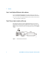
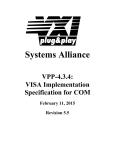
Step 2. Connect and set up the oscilloscope
The 6000 Series oscilloscope has three different interfaces you can use for
programming: USB (device), LAN, or GPIB. All three interfaces are “live” by
default, but you can turn them off if desired. To access these settings press the
Utility key on the front panel, then press the I/O softkey, then press the Control
softkey.
USB
HOST DEVICE
LAN Non-Auto-MDIX
GPIB
54684e69.cdr
Figure 1
8
Control Connectors on Rear Panel
Agilent 6000 Series Oscilloscopes Programmer’s Quick Start Guide
Setting Up
1
Using the USB (Device) Interface
1 Connect a USB cable from the controller PC’s USB port to the “USB
DEVICE” port on the back of the oscilloscope.
This is a USB 2.0 high speed port.
2 On the oscilloscope, verify that the controller interface is enabled:
a Press the Utility button.
b Using the softkeys, press I/O and Controller.
c Ensure the box next to USB is selected( ). If not( ), use the Entry
knob to select USB; then, press the Control softkey again.
Using the LAN Interface
1 If the controller PC isn’t already connected to the local area network (LAN),
do that first.
2 Get the oscilloscope’s network parameters (hostname, domain, IP address,
subnet mask, gateway IP, DNS IP, etc.) from your network administrator.
3 Connect the oscilloscope to the local area network (LAN) by inserting LAN
cable into the “LAN” port on the back of the oscilloscope.
4 On the oscilloscope, verify that the controller interface is enabled:
a Press the Utility button.
b Using the softkeys, press I/O and Controller.
c Ensure the box next to LAN is selected( ). If not( ), use the Entry
knob to select LAN; then, press the Control softkey again.
5 Configure the oscilloscope’s LAN interface:
a Press the Configure softkey until “LAN” is selected.
b Press the LAN Settings softkey.
c Press the Addresses softkey. Use the IP Options softkey and the Entry
knob to select DHCP, AutoIP, or netBIOS. Use the Modify softkey (and
the other softkeys and the Entry knob) to enter the IP Address, Subnet
Mask, Gateway IP, and DNS IP values. When you are done, press the
return (up arrow) softkey.
d Press the Domain softkey. Use the Modify softkey (and the other
softkeys and the Entry knob) to enter the Host name and the Domain
name. When you are done, press the return (up arrow) softkey.
Agilent 6000 Series Oscilloscopes Programmer’s Quick Start Guide
9
1
Setting Up
Using the GPIB Interface
1 Connect a GPIB cable from the controller PC’s GPIB interface to the “GPIB”
port on the back of the oscilloscope.
2 On the oscilloscope, verify that the controller interface is enabled:
a Press the Utility button.
b Using the softkeys, press I/O and Controller.
c Ensure the box next to GPIB is selected( ). If not( ), use the Entry
knob to select GPIB; then, press the Control softkey again.
3 Configure the oscilloscope’s GPIB interface:
a Press the Configure softkey until “GPIB” is selected.
b Use the Entry knob to select the Address value.
10
Agilent 6000 Series Oscilloscopes Programmer’s Quick Start Guide
Setting Up
1
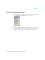
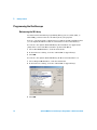
Step 3. Verify the oscilloscope connection
1 On the controller PC, click on the Agilent IO Control icon in the taskbar and
choose Agilent Connection Expert from the popup menu.
2 In the Agilent Connection Expert application, instruments connected to the
controller’s USB and GPIB interfaces should automatically appear. (You can
click Refresh All to update the list of instruments on these interfaces.)
Agilent 6000 Series Oscilloscopes Programmer’s Quick Start Guide
11
1
Setting Up
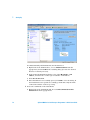
You must manually add instruments on LAN interfaces:
a Right-click on the LAN interface, choose Add Instrument from the
popup menu, and click OK in the resulting dialog (because the desired
interface is already selected).
b In the next LAN Instrument dialog, select either Hostname or IP
address, and enter the oscilloscope’s hostname or IP address.
c Click Test Connection.
d If the instrument is successfully opened, click OK to close the dialog. If
the instrument is not opened successfully, go back and verify the LAN
connections and the oscilloscope setup.
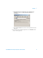
3 Test some commands on the instrument:
a Right-click on the instrument and choose Send Commands To This
Instrument from the popup menu.
12
Agilent 6000 Series Oscilloscopes Programmer’s Quick Start Guide
Setting Up
1
b In the Agilent Interactive IO application, enter commands in the
Command field and press Send Command, Read Response, or
Send & Read.
c Choose Connect>Exit from the menu to exit the Agilent Interactive IO
application.
4 In the Agilent Connection Expert application, choose File>Exit from the
menu to exit the application.
Agilent 6000 Series Oscilloscopes Programmer’s Quick Start Guide
13
1
Setting Up
Step 4. Access the Programmer’s Reference
The Programmer’s Reference is supplied on CD as a help file readable with
the Microsoft Windows help viewer. The Programmer’s Reference help file
describes oscilloscope command syntax and status reporting data structures.
It also contains sample programs that you can cut-and-paste from.
To access the Programmer’s Reference help file
The Programmer’s Reference help file requires Microsoft Windows
95/98/NT/2000/XP.
1 Insert the “Programmer’s Documentation” CD into your PC’s CD-ROM
drive.
2 If a web browser window doesn’t auto-run, open the Readme.htm file on
the CD.
3 In the web browser window, click the Programmer’s Reference link.
To get the latest versions via the web
The latest versions of the Programmer’s Reference help file and other
manuals are available on the world-wide web at:
www.agilent.com/find/mso6000
14
Agilent 6000 Series Oscilloscopes Programmer’s Quick Start Guide
Agilent 6000 Series Oscilloscopes
Programmer’s Quick Start Guide
2
Getting Started
Basic Oscilloscope Program Structure 16
Programming the Oscilloscope 18
This chapter gives you an overview of programming the 6000 Series
oscilloscopes. It describes basic oscilloscope program structure and shows
how to program the oscilloscope using a few simple examples.
The getting started examples show how to send oscilloscope setup, data
capture, and query commands, and they show how to read query results.
NOTE
Language for Program Examples
The programming examples in this quick start guide are written in Visual Basic using the
Agilent VISA COM library.
Agilent Technologies
15
2
Getting Started
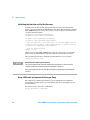
Basic Oscilloscope Program Structure
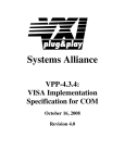
The following figure shows the basic structure of every program you will write
for the oscilloscope.
Initializing
To ensure consistent, repeatable performance, you need to start the program,
controller, and oscilloscope in a known state. Without correct initialization,
your program may run correctly in one instance and not in another. This might
be due to changes made in configuration by previous program runs or from
the front panel of the oscilloscope.
• Program initialization defines and initializes variables, allocates memory,
or tests system configuration.
• Controller initialization ensures that the interface to the oscilloscope
(GPIB, LAN, or USB) is properly set up and ready for data transfer.
• Oscilloscope initialization sets the channel configuration, channel labels,
threshold voltages, trigger specification, trigger mode, timebase, and
acquisition type.
16
Agilent 6000 Series Oscilloscopes Programmer’s Quick Start Guide
Getting Started
2
Capturing Data
Once you initialize the oscilloscope, you can begin capturing data for analysis.
Remember that while the oscilloscope is responding to commands from the
controller, it is not performing acquisitions. Also, when you change the
oscilloscope configuration, any data already captured will most likely be
rendered.
To collect data, you use the :DIGitize command. This command clears the
waveform buffers and starts the acquisition process. Acquisition continues
until acquisition memory is full, then stops. The acquired data is displayed by
the oscilloscope, and the captured data can be measured, stored in trace
memory in the oscilloscope, or transferred to the controller for further
analysis. Any additional commands sent while :DIGitize is working are
buffered until :DIGitize is complete.
You could also put the oscilloscope into run mode, then use a wait loop in your
program to ensure that the oscilloscope has completed at least one acquisition
before you make a measurement. Agilent does not recommend this because the
needed length of the wait loop may vary, causing your program to fail.
:DIGitize, on the other hand, ensures that data capture is complete. Also,
:DIGitize, when complete, stops the acquisition process so that all
measurements are on displayed data, not on a constantly changing data set.
Analyzing Captured Data
After the oscilloscope has completed an acquisition, you can find out more
about the data, either by using the oscilloscope measurements or by
transferring the data to the controller for manipulation by your program.
Built-in measurements include: frequency, duty cycle, period, positive pulse
width, and negative pulse width.
Using the :WAVeform commands, you can transfer the data to your controller.
You may want to display the data, compare it to a known good measurement,
or simply check logic patterns at various time intervals in the acquisition.
Agilent 6000 Series Oscilloscopes Programmer’s Quick Start Guide
17
2
Getting Started
Programming the Oscilloscope
Referencing the IO Library
No matter which instrument programming library you use (SICL, VISA, or
VISA COM), you must reference the library from your program.
In C/C++, you must tell the compiler where to find the include and library files
(see the Agilent IO Libraries Suite documentation for more information).
To reference the Agilent VISA COM library in Visual Basic for Applications
(VBA, which comes with Microsoft Office products like Excel):
1 Choose Tools>References... from the main menu.
2 In the References dialog, check the “VISA COM 3.0 Type Library”.
3 Click OK.
To reference the Agilent VISA COM library in Microsoft Visual Basic 6.0:
1 Choose Project>References... from the main menu.
2 In the References dialog, check the “VISA COM 3.0 Type Library”.
3 Click OK.
18
Agilent 6000 Series Oscilloscopes Programmer’s Quick Start Guide
2
Getting Started
Opening the Oscilloscope Connection via the IO Library
PC controllers communicate with the oscilloscope by sending and receiving
messages over a remote interface. Once you have opened a connection to the
oscilloscope over the remote interface, programming instructions normally
appear as ASCII character strings embedded inside write statements of the
programing language. Read statements are used to read query responses from
the oscilloscope.
For example, when using the Agilent VISA COM library in Visual Basic (after
opening the connection to the instrument using the ResourceManager object’s
Open method), the FormattedIO488 object’s WriteString, WriteNumber,
WriteList, or WriteIEEEBlock methods are used for sending commands and
queries. After a query is sent, the response is read using the ReadString,
ReadNumber, ReadList, or ReadIEEEBlock methods.
The following Visual Basic statements open the connection and send a
command that turns on the oscilloscope’s label display.
Dim myMgr As VisaComLib.ResourceManager
Dim myScope As VisaComLib.FormattedIO488
Set myMgr = New VisaComLib.ResourceManager
Set myScope = New VisaComLib.FormattedIO488
' Open the connection to the oscilloscope. Get the VISA Address from the
' Agilent Connection Expert (installed with Agilent IO Libraries Suite).
Set myScope.IO = myMgr.Open("<VISA Address>")
' Send a command.
myScope.WriteString “:DISPLAY:LABEL ON"
The “:DISPLAY:LABEL ON” in the above example is called a program message.
Program messages are explained in more detail in the online Programmer’s
Reference.
Agilent 6000 Series Oscilloscopes Programmer’s Quick Start Guide
19
2
Getting Started
Initializing the Interface and the Oscilloscope
To make sure the bus and all appropriate interfaces are in a known state,
begin every program with an initialization statement. When using the Agilent
VISA COM library, you can use the resource session object’s Clear method to
clears the interface buffer:
Dim myMgr As VisaComLib.ResourceManager
Dim myScope As VisaComLib.FormattedIO488
Set myMgr = New VisaComLib.ResourceManager
Set myScope = New VisaComLib.FormattedIO488
' Open the connection to the oscilloscope. Get the VISA Address from the
' Agilent Connection Expert (installed with Agilent IO Libraries Suite).
Set myScope.IO = myMgr.Open("<VISA Address>")
' Clear the interface buffer.
myScope.IO.Clear
When you are using GPIB, CLEAR also resets the oscilloscope’s parser. The
parser is the program which reads in the instructions which you send it.
After clearing the interface, initialize the instrument to a preset state:
myScope.WriteString “*RST"
NOTE
Information for Initializing the Instrument
The actual commands and syntax for initializing the instrument are discussed in the
common commands section of the online Programmer’s Reference.
Refer to the Agilent IO Libraries Suite documentation for information on initializing the
interface.
Using :AUToscale to Automate Oscilloscope Setup
The :AUToscale command performs a very useful function for unknown
waveforms by setting up the vertical channel, time base, and trigger level of
the instrument.
The syntax for the autoscale command is:
myScope.WriteString “:AUTOSCALE"
20
Agilent 6000 Series Oscilloscopes Programmer’s Quick Start Guide
2
Getting Started
Using Other Oscilloscope Setup Commands
A typical oscilloscope setup would set the vertical range and offset voltage, the
horizontal range, delay time, delay reference, trigger mode, trigger level, and
slope. An example of the commands that might be sent to the oscilloscope are:
myScope.WriteString
myScope.WriteString
myScope.WriteString
myScope.WriteString
myScope.WriteString
myScope.WriteString
“:CHANNEL1:PROBE 10"
“:CHANNEL1:RANGE 16"
“:CHANNEL1:OFFSET 1.00"
“:TIMEBASE:MODE NORMAL"
“:TIMEBASE:RANGE 1E-3"
“:TIMEBASE:DELAY 100E-6"
Vertical is set to 16 V full-scale (2 V/div) with center of screen at 1 V and probe
attenuation set to 10. This example sets the time base at 1 ms full-scale
(100 ms/div) with a delay of 100 µs.
Example Oscilloscope Setup Code
This program demonstrates the basic command structure used to program the
oscilloscope.
' Initialize the instrument interface to a known state.
myScope.IO.Clear
' Initialize the instrument to a preset state.
myScope.WriteString "*RST"
' Set the time base
' with 0 s of delay
myScope.WriteString
myScope.WriteString
myScope.WriteString
mode to normal with the horizontal time at 50 ms/div
referenced at the center of the graticule.
":TIMEBASE:RANGE 5E-4"
' Time base to 50 us/div.
":TIMEBASE:DELAY 0"
' Delay to zero.
":TIMEBASE:REFERENCE CENTER" ' Display ref. at center.
' Set the vertical range to 1.6 volts full scale with center screen at
' -0.4 volts with 10:1 probe attenuation and DC coupling.
myScope.WriteString ":CHANNEL1:PROBE 10"
' Probe attenuation to 10:1.
myScope.WriteString ":CHANNEL1:RANGE 1.6"
' Vert rng1.6 V full scale.
myScope.WriteString ":CHANNEL1:OFFSET -.4"
' Offset to -0.4.
myScope.WriteString ":CHANNEL1:COUPLING DC"
' Coupling to DC.
' Configure the instrument to trigger at -0.4 volts with normal
' triggering.
myScope.WriteString ":TRIGGER:SWEEP NORMAL"
' Normal triggering.
myScope.WriteString ":TRIGGER:LEVEL -.4"
' Trigger level to -0.4.
myScope.WriteString ":TRIGGER:SLOPE POSITIVE"
' Trigger on pos. slope.
' Configure the instrument for normal acquisition.
myScope.WriteString ":ACQUIRE:TYPE NORMAL"
' Normal acquisition.
Agilent 6000 Series Oscilloscopes Programmer’s Quick Start Guide
21
2
Getting Started
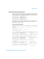
Capturing Data with the :DIGitize Command
The :DIGitize command captures data that meets the specifications set up by
the :ACQuire subsystem. When the digitize process is complete, the acquisition
is stopped. The captured data can then be measured by the instrument or
transferred to the controller for further analysis. The captured data consists of
two parts: the waveform data record, and the preamble.
NOTE
Ensure New Data is Collected
When you change the oscilloscope configuration, the waveform buffers are cleared. Before
doing a measurement, send the :DIGitize command to the oscilloscope to ensure new data
has been collected.
When you send the :DIGitize command to the oscilloscope, the specified
channel signal is digitized with the current :ACQuire parameters. To obtain
waveform data, you must specify the :WAVeform parameters for the SOURce
channel, the FORMat type, and the number of POINts prior to sending the
:WAVeform:DATA? query.
NOTE
Set :TIMebase:MODE to MAIN or DELayed when using :DIGitize
:TIMebase:MODE must be set to MAIN or DELayed to perform a :DIGitize command or to
perform any :WAVeform subsystem query. A "Settings conflict" error message will be
returned if these commands are executed when MODE is set to ROLL or XY. Sending the
*RST (reset) command will set the time base mode to main.
The number of data points comprising a waveform varies according to the
number requested in the :ACQuire subsystem. The :ACQuire subsystem
determines the number of data points, type of acquisition, and number of
averages used by the :DIGitize command. This allows you to specify exactly
what the digitized information contains.
22
Agilent 6000 Series Oscilloscopes Programmer’s Quick Start Guide
Getting Started
2
The following program example shows a typical setup:
myScope.WriteString
myScope.WriteString
myScope.WriteString
myScope.WriteString
myScope.WriteString
myScope.WriteString
myScope.WriteString
myScope.WriteString
":ACQUIRE:TYPE AVERAGE"
":ACQUIRE:COMPLETE 100"
":ACQUIRE:COUNT 8"
":DIGITIZE CHANNEL1"
":WAVEFORM:SOURCE CHANNEL1"
":WAVEFORM:FORMAT BYTE"
":WAVEFORM:POINTS 500"
":WAVEFORM:DATA?"
This setup places the instrument into the averaged mode with eight averages.
This means that when the :DIGitize command is received, the command will
execute until the signal has been averaged at least eight times.
After receiving the :WAVeform:DATA? query, the instrument will start passing
the waveform information.
Digitized waveforms are passed from the instrument to the controller by
sending a numerical representation of each digitized point. The format of the
numerical representation is controlled with the :WAVeform:FORMat command
and may be selected as BYTE, WORD, or ASCii.
The easiest method of transferring a digitized waveform depends on data
structures, formatting available and I/O capabilities. You must scale the
integers to determine the voltage value of each point. These integers are
passed starting with the left most point on the instrument’s display.
For more information, see the waveform subsystem commands and
corresponding program code examples in the online Programmer’s Reference.
NOTE
Aborting a Digitize Operation Over GPIB
When using GPIB, you can abort a digitize operation by sending a Device Clear over the bus
(for example, myScope.IO.Clear).
Agilent 6000 Series Oscilloscopes Programmer’s Quick Start Guide
23
2
Getting Started
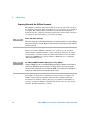
Reading Query Responses from the Oscilloscope
After receiving a query (command header followed by a question mark), the
instrument interrogates the requested function and places the answer in its
output queue. The answer remains in the output queue until it is read or
another command is issued. When read, the answer is transmitted across the
interface to the designated listener (typically a controller).
The statement for reading a query response message from an instrument’s
output queue typically has a format specification for handling the response
message.
When using the VISA COM library in Visual Basic, you use different read
methods (ReadString, ReadNumber, ReadList, or ReadIEEEBlock) for the
various query response formats. For example, to read the result of the query
command :CHANnel1:COUPling? you would execute the statements:
myScope.WriteString ":CHANNEL1:COUPLING?"
Dim strQueryResult As String
strQueryResult = myScope.ReadString
This reads the current setting for the channel one coupling into the string
variable strQueryResult.
All results for queries (sent in one program message) must be read before
another program message is sent.
Sending another command before reading the result of the query clears the
output buffer and the current response. This also causes an error to be placed
in the error queue.
Executing a read statement before sending a query causes the controller to
wait indefinitely.
The format specification for handling response messages depends on the
programming language.
24
Agilent 6000 Series Oscilloscopes Programmer’s Quick Start Guide
Getting Started
2
Reading Query Results into String Variables
The output of the instrument may be numeric or character data depending on
what is queried. Refer to the specific command descriptions in the online
Programmer’s Reference for the formats and types of data returned from
queries.
NOTE
Express String Variables Using Exact Syntax
In Visual Basic, string variables are case sensitive and must be expressed exactly the same
each time they are used.
The following example shows numeric data being returned to a string variable:
myScope.WriteString ":CHANNEL1:RANGE?"
Dim strQueryResult As String
strQueryResult = myScope.ReadString
MsgBox "Range (string):" + strQueryResult
After running this program, the controller displays:
Range (string): +40.0E+00
Reading Query Results into Numeric Variables
The following example shows numeric data being returned to a numeric
variable:
myScope.WriteString ":CHANNEL1:RANGE?"
Dim varQueryResult As Variant
strQueryResult = myScope.ReadNumber
MsgBox "Range (variant):" + CStr(varQueryResult)
After running this program, the controller displays:
Range (variant): 40
Agilent 6000 Series Oscilloscopes Programmer’s Quick Start Guide
25
2
Getting Started
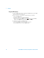
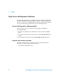
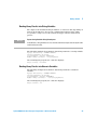
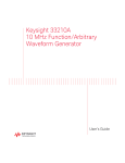
Reading Definite-Length Block Query Response Data
Definite-length block query response data allows any type of device-dependent
data to be transmitted over the system interface as a series of 8-bit binary data
bytes. This is particularly useful for sending large quantities of data or 8-bit
extended ASCII codes. The syntax is a pound sign (#) followed by a non-zero
digit representing the number of digits in the decimal integer. After the
non-zero digit is the decimal integer that states the number of 8-bit data bytes
being sent. This is followed by the actual data.
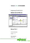
For example, for transmitting 1000 bytes of data, the syntax would be:
Number of Digits
That Follow
Actual Data
#800001000<1000 bytes of data><terminator>
Number of Bytes
to be Transmitted
Figure 2
Definite-length block response data
The “8” states the number of digits that follow, and “00001000” states the
number of bytes to be transmitted.
The VISA COM library’s ReadIEEEBlock and WriteIEEEBlock methods
understand the definite-length block syntax, so you can simply use variables
that contain the data:
' Read oscilloscope setup using ":SYSTEM:SETUP?" query.
myScope.WriteString ":SYSTEM:SETUP?"
Dim varQueryResult As Variant
varQueryResult = myScope.ReadIEEEBlock(BinaryType_UI1)
' Write learn string back to oscilloscope using ":SYSTEM:SETUP" command:
myScope.WriteIEEEBlock ":SYSTEM:SETUP ", varQueryResult
26
Agilent 6000 Series Oscilloscopes Programmer’s Quick Start Guide
2
Getting Started
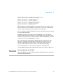
Sending Multiple Queries and Reading Results
You can send multiple queries to the instrument within a single command
string, but you must also read them back as a single query result. This can be
accomplished by reading them back into a single string variable, multiple
string variables, or multiple numeric variables.
For example, to read the :TIMebase:RANGe?;DELay? query result into a single
string variable, you could use the commands:
myScope.WriteString ":TIMEBASE:RANGE?;DELAY?"
Dim strQueryResult As String
strQueryResult = myScope.ReadString
MsgBox "Timebase range; delay:" + strQueryResult
When you read the result of multiple queries into a single string variable, each
response is separated by a semicolon. For example, the output of the previous
example would be:
Timebase range; delay: <range_value>;<delay_value>
To read the :TIMebase:RANGe?;DELay? query result into multiple string
variables, you could use the ReadList method to read the query results into a
string array variable using the commands:
myScope.WriteString ":TIMEBASE:RANGE?;DELAY?"
Dim strResults() As String
strResults() = myScope.ReadList(ASCIIType_BSTR)
MsgBox "Timebase range: " + strResults(0) + ", delay: " + strResults(1)
To read the :TIMebase:RANGe?;DELay? query result into multiple numeric
variables, you could use the ReadList method to read the query results into a
variant array variable using the commands:
myScope.WriteString ":TIMEBASE:RANGE?;DELAY?"
Dim varResults() As Variant
varResults() = myScope.ReadList
MsgBox "Timebase range: " + FormatNumber(varResults(0) * 1000, 4) + _
" ms, delay: " + FormatNumber(varResults(1) * 1000000, 4) + " us"
Checking Instrument Status
Status registers track the current status of the instrument. By checking the
instrument status, you can find out whether an operation has been completed,
whether the instrument is receiving triggers, and more.
For more information, see the “Status Reporting” topic in the online
Programmer’s Reference which explains how to check the status of the
instrument.
Agilent 6000 Series Oscilloscopes Programmer’s Quick Start Guide
27
2
Getting Started
Other Ways of Sending Commands
Standard Commands for Programmable Instrumentation (SCPI) can be sent
via a Telnet socket or through the Browser Web Control.
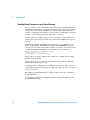
Telnet Sockets
The following information is provided for those programmers who wish to
control the oscilloscope with SCPI commands in a Telnet session.
To connect to the oscilloscope via a telnet socket, issue the following
command:
telnet <hostname> 5024
where <hostname> is the hostname of the oscilloscope.
This will give you a command line with prompt.
For a command line without a prompt:
Use port 5025.
Example:
telnet <hostname> 5025
Sending SCPI Commands using Browser Web Control
To send SCPI commands using the Browser Web Control feature, establish a
connection to the oscilloscope via LAN as described in the 6000 Series
Oscilloscopes User’s Guide. When you make the connection to the oscilloscope
via LAN and the instrument’s welcome page is displayed, select the Browser
Web Control tab, then select the Remote Programming link.
28
Agilent 6000 Series Oscilloscopes Programmer’s Quick Start Guide
Index
Numerics
F
O
82350A GPIB interface, 4
FormattedIO488 object, 19
frequency measurement, 17
on the web, 14
Open method, 19
oscilloscope
command syntax, 14
connecting, 8
connection, opening, 19
initialization, 16
operation, 4
program structure, 16
setting up, 8
setup, 21
verifying connection, 11
A
ACQuire subsystem, 22
Addresses softkey, 9
Agilent Connection Expert, 11
Agilent Interactive IO application, 13
Agilent IO Control icon, 11
Agilent IO Libraries Suite, 3, 4, 7, 18, 20
installing, 8
analyzing captured data, 17
Automation-Ready CD, 8
AUToscale command, 20
B
basic operations, 3
block response data, 26
built-in measurements, 17
C
G
gateway IP, 9
GPIB interface, 8, 10
H
help file, 14
accessing, 14
hostname, 9
I
I/O softkey, 9, 10
initialization, 16, 20
instrument status, 27
IO library, referencing, 18
IP address, 9
IP Options softkey, 9
P
period measurement, 17
positive pulse width measurement, 17
program initialization, 16
program message, 19
program structure, 16
Programmer’s Documentation CD, 14
Programmer’s Reference, 4
accessing, 14
pulse width measurement, 17
capturing data, 17
Clear method, 20
command syntax, 14
Configure softkey, 9, 10
connect oscilloscope, 8
controller initialization, 16
Controller softkey, 9, 10
L
D
measurements, built-in, 17
Modify softkey, 9
multiple queries, 27
queries, multiple, 27
query responses
block data, 26
reading, 24
query results
reading into numeric variables, 25
reading into string variables, 25
N
R
negative pulse width measurement, 17
numeric variables, 25
reading query results into multiple, 27
ReadIEEEBlock method, 19, 24, 26
ReadList method, 24
ReadNumber method, 19, 24
definite-length block query response, 26
DIGitize command, 17, 22
DNS IP, 9
domain, 9
Domain softkey, 9
duty cycle measurement, 17
LAN interface, 8, 9, 12
LAN Settings softkey, 9
language for program examples, 15
M
Agilent 6000 Series Oscilloscopes Programmer’s Quick Start Guide
Q
29
Index
ReadString method, 19, 24
resource session object, 20
ResourceManager object, 19
S
sample programs, 14
SCPI commands, 28
set up oscilloscope, 8
SICL library, 3
status registers, 27
status reporting data structures, 14
string variables, 25
reading multiple query results into, 27
reading query results into multiple, 27
subnet mask, 9
syntax, command, 14
T
Telnet sockets, 28
TIMebase:MODE, 22
U
USB (Device) interface, 8, 9
User’s Guide, 4
Utility button, 9, 10
V
VBA, 18
VISA COM library, 3
VISA library, 3
Visual Basic 6.0, 18
Visual Basic for Applications, 18
W
WAVeform command, 17
WAVeform parameters, 22
WAVeform:FORMat, 23
Web control, 28
WriteIEEEBlock method, 19, 26
WriteList method, 19
WriteNumber method, 19
WriteString method, 19
30
Agilent 6000 Series Oscilloscopes Programmer’s Quick Start Guide
Index
Agilent 6000 Series Oscilloscopes Programmer’s Quick Start Guide
31
Index
.
32
Agilent 6000 Series Oscilloscopes Programmer’s Quick Start Guide