1
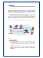
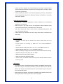
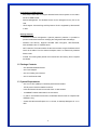
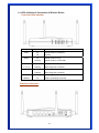
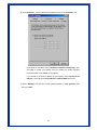
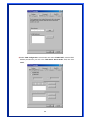
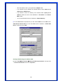
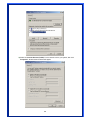
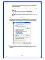
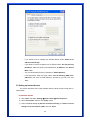
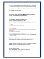
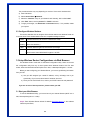
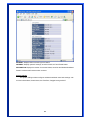
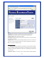
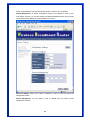
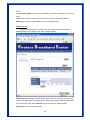
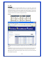
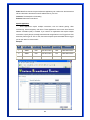
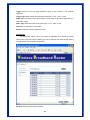
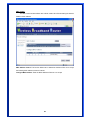
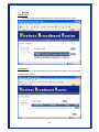
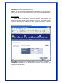
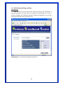
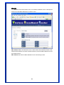
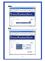
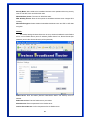
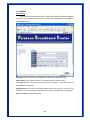
802.11g, 54Mbps
MIMO Wireless Broadband
Router
User’s Manual
Model # AWR-MIMO-54RA
1
FCC Warning
This equipment has been tested and found to comply with the limits for a Class B digital device,
pursuant to part 15 of the FCC Rules. These limits are designed to provide reasonable
protection against harmful interference in a residential installation. This equipment generates,
uses, and can radiate radio frequency energy and, if not installed and used in accordance with
the instructions, may cause harmful interference to radio communication. However, there is no
guarantee that interference will not occur in a particular installation. If this equipment does
cause harmful interference to radio or television reception, which can be determined by turning
the equipment off and on, the user is encouraged to try to correct the interference by one or
more of the following measures:
-
Reorient or relocate the receiving antenna.
-
Increase the separation between the equipment and receiver.
-
Connect the equipment into an outlet on a circuit different from that to which
-
Consult the dealer or an experienced radio/TV technician for help. the receiver is
connected.
FCC Caution: Any changes or modifications not expressly approved by the party responsible
for compliance could void the user’s authority to operate this equipment.
This device complies with Part 15 of the FCC Rules. Operation is subject to the following two
conditions: (1) This device may not cause harmful interference, and (2) this device must
accept any interference received, including interference that may cause undesired operation.
IMPORTANT NOTE:
FCC Radiation Exposure Statement:
This equipment complies with FCC radiation exposure limits set forth for an uncontrolled
environment. This equipment should be installed and operated with a minimum distance of
about eight inches (20cm) between the radiator and your body.
This transmitter must not be co-located or operated in conjunction with any other antenna or
transmitter.
Notice
Changes or modifications to the equipment, which are not approved by the party responsible for
compliance could affect the user's authority to operate the equipment. Company has an on-going policy
of upgrading its products and it may be possible that information in this document is not up-to-date.
Please check with your local distributors for the latest information.
2
Copyright
2006 All Rights Reserved.
No part of this document can be copied or reproduced in any form without written consent from
the company.
Trademarks:
All trade names and trademarks are the properties of their respective companies.
Revision History
Revision
History
V1.0
First release
3
Table of Contents
1. Introduction ..................................................................................... 5
1.1 Features............................................................................................. 5
1.2 Package Contents ............................................................................ 7
1.3 System Requirements ..................................................................... 7
1.4 LEDs Indication & Connectors of Wireless Router ...................... 8
1.5 Installation Instruction..................................................................... 9
2. PC Configuration........................................................................... 10
2.1 TCP/IP Networking Setup .............................................................. 10
2.2 Setting up Internet Access............................................................ 17
2.3 Configure Wireless Stations ......................................................... 19
3. Setup Wireless Router Configurations via Web Browser .......... 19
3.1 Start your Web Browser ................................................................ 19
3.2 System............................................................................................. 20
3.3 WAN ................................................................................................. 28
3.4 LAN .................................................................................................. 30
3.5 NAT .................................................................................................. 32
3.6 Firewall ............................................................................................ 37
3.7 Routing ............................................................................................ 41
3.8 UPnP (Universal Plug and Play) ................................................... 43
3.9 DDNS ............................................................................................... 44
3.10 Wireless......................................................................................... 45
3.11 Wizard............................................................................................ 52
3.12 Help................................................................................................ 55
3.13 Logout ........................................................................................... 56
4. Troubleshooting ............................................................................ 57
4
1. Introduction
This Four ports MIMO Wireless Broadband Router is a full-featured wireless broadband
router that establishes wireless connection from AP then provides direct connection to local
area network or individual PC with build-in 4-port switch. This gateway uses advanced
broadband router chipset and wireless LAN chipset solution let you enjoy high-speed Wired
and Wireless connection. Simply connect this gateway to a cable or DSL modem and then you
can share your high-speed Internet access with multiple PCs at your home. This gateway also
creates a secure Wired and Wireless network for you to share photos, files, video and so on.
This gateway provides maximum transfer rate up to 90 Mbps from WAN to LAN, 100
Mbps from LAN to LAN and 11/54 Mbps through wireless channel. Built-in DHCP server
automatically to assign IP addresses to all workstations on your LAN. It supports the advanced
wireless security WPA and WPA2 standards to guarantee the best security for users. It also
has firewall and NAT function to help prevent potential attacks from the Internet.
1.1 Features
Internet Access Features
• Shared Internet Access: All users on the LAN or WLAN can access the Internet
through the Wireless Router, using only a single external IP address. The local
(invalid) IP addresses are hidden from external sources. This process is called NAT
(Network Address Translation).
• DSL and cable modem Support: The Wireless Router has a 10/100BaseT Ethernet
WAN port for connecting a DSL or cable modem. All popular DSL and cable modems
are supported.
5
• PPPoE and PPTP Support: The Internet (WAN port) connection supports PPPoE
(PPP over Ethernet) and PPTP (Point-to-Point Tunneling Protocol), as well as “Direct
Connection” type services.
• Fixed or Dynamic IP Address: On the Internet (WAN port) connection, the Wireless
Router supports both Dynamic IP address (IP address is allocated on connection)
and Fixed IP address.
Advanced Internet Functions
• Conferencing & Telephony Applications: Internet Telephony and Conferencing
applications are supported.
• DMZ: One PC on your local LAN can be configured to allow unrestricted 2-way
communication with Servers or individual users on the Internet.
• URL Filter: Use the URL Filter to block access to undesirable Web sites by LAN
users, or Wireless LAN users.
• Internet Access Log: This feature is used to verify which Internet connections have
been made.
Wireless Features
• Compatible with IEEE 802.11g standard and maximum data transfer rate up to
54Mbps
• Increase Speed and Coverage by MIMO XRTM and Packet-OVERDRIVETM
Technology
• Dynamic date rate scaling at 54, 48, 36, 24, 18, 12, 9 and 6Mbps for 802.11g
• Dynamic date rate scaling at 11, 5.5, 2 and 1Mbps for 802.11b
• Maximum reliability, throughput and connectivity with automatic data rate switching
• Supports Quality of Service (QoS), 802.11e, WMM
• Range extension by using external antenna
• Simple user setup and diagnostics utilities
• Access Control: This feature ensures that only access Wireless Stations that can
access your LAN.
LAN Features
• 4-Port Ethernet switch: The Wireless Router provides 4 10/100BaseT switching ports
• DHCP Server Support: This feature provides a dynamic IP address to PCs and other
devices upon request. The Wireless Router can act as a DHCP Server for devices on
your local LAN and WLAN.
• Multi Segment LAN Support: This feature is enabled through Wireless Router’s RIP
(Routing Information Protocol) and build-in static routing table.
6
Configuration and Management
• Easy Setup: Users allow to configure Wireless Router from anywhere on the LAN or
WLAN via WEB browser.
• Remote Management: The Wireless Router can be managed from any PC on the
LAN.
• UPnP Support: Universal Plug and Play feature. UPnP is supported by Windows ME
or later.
Security Features
• Password Protected Configuration: Optional password protection is provided to
prevent unauthorized users from modifying the configuration data and settings.
• Wireless LAN Security: Supports 64/128bit WEP Encryption, WPA-TKIP/PSK,
WP2-AES/PSK, 802.11i, RADIUS Server.
• NAT Protection: This feature allows all LAN users to share a single IP address and all
users’ IPs is hidden. From the external viewpoint, there is no network only Wireless
Router exists.
• Firewall: All incoming data packets are monitored and all incoming server requests
are filtered.
1.2 Package Contents
• One Wireless Broadband Router
• One Power Adapter
• One CD including user’s manual
• One RJ-45 Ethernet Cable
1.3 System Requirements
• One or more PCs (desktop or notebook) with Ethernet interface.
• TCP/IP protocol must be installed on all PCs.
• Have valid Internet Access account and a DSL or cable modem.
• 10/100BaseT network cables with RJ-45 connectors.
• In case to use Wireless Access Point, all Wireless devices must be compliant with
IEEE 802.11b/g.
• System with MS Internet Explorer ver. 5.0 or later, or Netscape Navigator ver. 4.7 or
later.
7
1.4 LEDs Indication & Connectors of Wireless Router
Front Panel LEDs Indication
LED
Light Status
PWR
On
Wireless Router is powered on.
Off
No power.
On
Wireless Router is hung.
Status
Flashing
LAN
On
(1, 2, 3, 4)
Flashing
WAN
On
Description
Wireless Router is up and ready.
LAN port is successfully connected.
Data is being sent or received.
WAN port is successfully connected
Flashing
Data is being sent or received.
WLAN
Flashing
Data is being sent or received.
LINK/ACT
On
WLAN is successfully connected.
Back Panel Connectors
8
Button/port
Description
Reset
Reset configurations to default. Press the button and hold for 10 seconds.
LAN
Connect LAN systems with RJ-45 cable.
(1x, 2x, 3x, 4x)
WAN
Connect DSL or Cable modem.
PWR
Connect with Power Adapter.
1.5 Installation Instruction
1) Power off Wireless Router and DSL/cable modem.
2) Connect systems to the LAN ports on the Wireless Router with straight LAN cables.
3) Connect the DSL or cable modem to the WAN port on the Wireless Router.
4) Power on DSL or cable modem first, then connect power adapter to the power jack
on the rear panel of Wireless Router and plug the power cable into an outlet.
5) Check LEDs.
a) Once power on Wireless Router, Power LED should be on.
b) LAN LED should be on for each active LAN connection.
c) The WAN LED should be on when the DSL or cable modem is connected.
Warning: Only use the power adapter is provided from this package, use other power adapter
may cause hardware damage
9
2. PC Configuration
User needs to configure TCP/IP network settings, Internet access configuration and
Wireless configuration for each system within Wireless Router’s LAN network.
By default, Wireless Router acts as a DHCP server for server version of Windows, it
automatically assigns IP address to each system when systems boot up. For all non-server
version of Windows, the default TCP/IP setting acts as a DHCP client. If user chooses fixed IP
addresses for client systems, the Gateway of the client system must be set to the IP address
of the Wireless Router and DNS of the client system should be set to the address provided by
your ISP.
2.1 TCP/IP Networking Setup
Checking TCP/IP Settings for Windows 9x/Me
a) Select “Start Æ Control Panel Æ Network”, the window below will appear,
10
b) Click “Properties”, the window below will appear and then click “IP Address” tab,
• If you decide to use DHCP, select “Obtain an IP address automatically”, then
click “OK” to confirm your settings. Once you restart your system, Wireless
Router will obtain an IP address for this system.
• If you decide to use fixed IP address for your system, select “Specify an IP
address”, and make sure that IP Address and Subnet Mask are correct.
c) Select “Gateway” tab and enter correct gateway address in “New gateway” field,
then click “Add”,
11
d) Select “DNS Configuration” tab and make sure select “Enable DNS”, enter the DNS
address provides from your ISP in the “DNS Server Search Order” field, then click
“Add”,
12
Checking TCI/IP Setting for Windows NT4.0
a) Select “Control Panel Æ Network”, click “Protocols” tab then select “TCP/IP
protocol”, window shown as below will appear,
b) Click “Properties”, window shown as below will appear.
13
• Select the network card on your system from “Adapter” field.
• If you decide to use IP address from Wireless Router, select “Obtain an IP
address from a DHCP server”.
• If you decide to use the IP address you are desired, select “Specify an IP
address”. Make sure enter correct addresses in “IP Address” and “Subnet
Mask” fields.
• You must set Wireless Router’s IP address as “Default Gateway”.
c) To enter DNS address is provided from your ISP. Select “DNS” tab, click “Add” under
“DNS Service Search Order” list, then enter DNS Server IP address in “TCP/IP DNS
Server” window and click “Add”.
Checking TCP/IP Settings for Windows 2000
a) Select “Start Æ Control Panel Æ Network and Dial-up Connection” and right click
“Local Area Connection” then click “Properties”,
14
b) Select the “Internet Protocol (TCP/IP)” for the network card on your system, then click
“Properties”, window shown as below will appear.
15
• If you decide to use IP address from Wireless Router, select “Obtain an IP
address automatically”.
• If you decide to use the IP address you are desired, select “Use the following
IP address”. Make sure enter correct addresses in “IP Address” and “Subnet
Mask” fields.
• You must set Wireless Router’s IP address as “Default Gateway”.
• If the DNS Server fields are empty, select “Use the following DNS server
addresses” and enter the DNS address is provided by your ISP, then click
“OK”.
Checking TCP/IP Settings for Windows XP
a) Click “Start”, select “Control Panel Æ Network Connection” and right click “Local
Area Connection” then select “Properties”. The window shown as below will appear.
b) Select “Internet Protocol (TCP/IP)” then click “Properties”, window shown as below
will appear.
16
• If you decide to use IP address from Wireless Router, select “Obtain an IP
address automatically”.
• If you decide to use the IP address you are desired, select “Use the following
IP address”. Make sure enter correct addresses in “IP Address” and “Subnet
Mask” fields.
• You must set Wireless Router’s IP address as “Default Gateway”.
• If the DNS Server fields are empty, select “Use the following DNS server
addresses” and enter the DNS address is provided by your ISP, then click
“OK”.
2.2 Setting up Internet Access
This section describes how to setup Wireless Router Internet access through DSL or
cable modem.
For Windows 9x/2000
a) Click “Start” and select “Settings Æ Control Panel Æ Internet Options”.
b) Select “Connection” tab then click “Setup” button.
c) Select “I want to set up my Internet connection manually, or I want to connect
through a local area network (LAN)” then click “Next”.
17
d) Select “I connect through a local area network (LAN)” then click “Next”. Make
sure all the boxes on the following LAN Internet Configuration screen are unchecked.
e) Select “No” when “Do you want to set up an Internet mail account now?”
prompts out.
f)
Click “Finish” to end setup process.
For Windows XP
a) Click “Start” and select “Control Panel Æ Network and Internet Connections”.
b) Select “Set up or Change your Internet Connection”.
c) Click “Connection” tab, and then click the “Setup” button. Click “Cancel” in the
pop-up “Location Information” window.
d) Click “Next” in the “New Connection Wizard” window.
e) Select “Connect to the Internet” then click “Next”.
f)
Select “Set up my connection manually” then click “Next”.
g) Select “Connect using a broadband connection that is always on” then click
“Next”.
h) Click “Finish” to complete the setup process.
For Macintosh Clients
To access Internet via wireless router on Macintosh system, the set up procedures are
showing below:
a) Open the TCP/IP Control Panel.
b) Select Ethernet from the Connect via pop-up menu.
c) Select Using DHCP Server from the Configure pop-up menu. The DHCP Client ID
field can be left blank.
d) Close the TCP/IP panel and save your new settings.
If you decide to assign IP addresses manually instead of DHCP, set the Router Address
field with wireless router’s IP address and make sure DNS settings are correct.
For Linux Clients
To access Internet via the wireless router, you need to set the wireless router as the
“Gateway”. Make sure login as “root” before attempting any changes.
Fixed IP Address
Most Linux installations use fixed IP address, if you wish to use a fixed IP address, make
sure make the following changes.
a) Set “Default Gateway” with the IP address of the wireless router.
b) Make sure DNS settings are correct.
To act as a DHCP Client (recommended)
18
The procedures below may vary depending on version of Linux and X-windows shell.
a) Start X-Windows.
b) Select Control Panel Æ Network.
c) Select the “Interface” entry for your Network card. Normally, this is called “eth0”.
d) Click “Edit” button, set the “protocol” to “DHCP” and save.
e) To apply all changes, use Deactivate and Activate buttons, if it is possible, restart
your system.
2.3 Configure Wireless Stations
This section describes how to configure all the wireless stations use Wireless Router as
an Access Point. Each wireless station must have compatible settings as below.
Mode
All wireless stations must be set to “Infrastructure” mode.
SSID
This code must match the value uses for the Wireless Router. (Note: SSID
(ESSID) code is case sensitive.)
WEP
By default, WEP encryption is set to 64-bits 10 hex digit.
WPA
By default, WPA-PSK Pass Phrase is set at PassPhrase, WPA G-Rekey
Interval is set at 0 and WPA Data Encryption is at TKIP.
3. Setup Wireless Router Configurations via Web Browser
The Wireless Router comes with a web-based configuration utility. Users can access
this configuration utility from any of client system within Wireless Router’s LAN. For best
results, either use Microsoft Internet Explorer 5.0 or later, or Netscape Navigator 4.7 or later.
Before you start configuring your Wireless Router, you have to get following information
from your ISP:
a) Has your ISP assigned you a static IP address, or they will assign one to you
dynamically? If you have received static IP address, what is it?
b) Does your ISP use PPPoE? If so, what is your PPPoE username and password?
If you are not sure of above questions, please contact your ISP.
3.1 Start your Web Browser
To use the Web-Based Utility, you have to launch your Internet Browser (MS IE 5.0 or
later, Netscape Navigator 4.7 or later).
Step1: Enter Wireless Router default IP address http://192.168.10.1 in the Address
field then press Enter,
19
Step2: Login dialog box will appear, enter admin as User Name and default password is
1234, then click “OK” to login web-based utility.
3.2 System
This section displays the basic configuration parameters of your Wireless Router, such
as System Status, System Settings, Administrator Settings, Firmware Upgrade, Configuration
Tools and System Log. Although most users will be able for accept the default settings, but
every ISP is different. Please check with your ISP if you are not sure which settings ISP
requires.
System Status
You can use the Status screen to see the connection status for the Wireless Broadband
Router WAN/LAN interfaces, firmware and hardware version numbers, and the number of
connected clients to your network.
20
21
INTERNET: Displays WAN connection type and status.
GATEWAY: Displays system IP settings, as well as DHCP, NAT and Firewall status.
INFORMATION: Displays the number of connected clients, as well as the Wireless Broadband
Router's hardware and firmware version numbers.
System Settings
The System Settings window configures wireless broadband router basic settings, such
as router’s Host Name, Domain Name, Set Time Zone, Daylight Saving and NAT.
22
Host Name: Enter a hostname if it provided by the ISP (Default: Wireless_Router).
Domain Name: Enter a Domain Name if it provided by the ISP (Default: Router).
NTP Server (option): Enter a NTP Server IP Address.
Set Time Zone: Select the time zone of the country you are currently in. The router will set its
time based on your selection.
Daylight Saving: The router can also take Daylight savings into account. If you wish to use
this function, you must check/tick the enable box to enable your daylight saving configuration.
NAT: You can select to enable NAT function.
Administrator Settings
Use this menu to restrict management access based on a specific password. By default,
there is no password. So please assign a password to the Administrator as soon as possible,
and store it in a safe place. Passwords can contain from 3-12 alphanumeric characters, and
are case sensitive.
Administrator Time-out - The amount of time of inactivity before the Wireless Broadband
23
Router will automatically close the Administrator session. Set this to zero to disable it.
Remote Management - By default, management access is only available to users on your
local network. However, you can also manage the Wireless Broadband Router from a remote
host by adding the IP address of an administrator to this screen.
Password Settings: Allows you to select a password in order to access the web-based
management website.
Remote Management: You can specify a Host IP address that can perform remote
management functions.
24
Firmware Upgrade
User uses the Firmware Upgrade window to locate the new firmware then upgrade the
system firmware. Click Browse to search for the new firmware location, and then click OK to
proceed the upgrade.
Firmware Upgrade: This tool allows you to upgrade the Wireless Broadband router’s system
firmware. To upgrade the firmware of your Broadband router, you need to download the
firmware file to your local hard disk, and enter that file name and path in the appropriate field
on this page. You can also use the Browse button to find the firmware file on your PC.
25
Configuration Tools
Use this window to restore or backup wireless broadband router settings, such as
Restart System, Restore Factory Defaults, Backup Settings and Restore Settings.
Restart System: Reset Wireless Broadband Router, Reboot this device.
Restore Factory Defaults: Reset the settings of this device to the factory default values.
Backup Settings: Save the settings of this device to a file.
Restore Settings: Restore the settings of this device to the backup settings.
26
System Log
The System Log window displays wireless broadband router’s system activities, such as
System Log and Security Log.
System Log: Wireless broadband router’s system activity.
Remote Log Setting: Setting the IP address of remote log server.
27
3.3 WAN
Connected Type
Specify the WAN connection type required by your Internet Service Provider, then click
"OK" Button to provide detailed configuration parameters for the selected connection type.
Dynamic IP address: Your ISP will automatically give you an IP address
Static IP address: Your ISP has given you an IP address already
PPPoE: Your ISP requires PPPoE connection.
PPTP: Your ISP requires you to use a Point-to-Point Tunneling Protocol (PPTP) connection.
L2TP: Your ISP requires L2TP connection.
28
DNS
Domain Name Servers are used to map an IP address to the equivalent domain name
(e.g.www.waveplus.com). Your ISP should provide the IP address for one or more domain
name servers.
DNS Proxy: You can enable or disable the DNS Proxy.
Static DNS Server: You can enable or disable the Static DNS Server.
Domain Name Server (DNS) Address: This is the ISP’s DNS server IP address that they
gave you; or you can specify your own preferred DNS server IP address
Secondary DNS Address (optional): This is optional. You can enter another DNS server’s IP
address as a backup. The secondary DNS will be used should the above DNS fail.
Search Static DNS Firstly: You can enable or disable the function of Search Static DNS
Firstly.
29
3.4 LAN
LAN Settings
Configure the gateway address of the Wireless Broadband Router. To dynamically
assign the IP address for client PCs, enable the DHCP Server, set the lease time, and then
specify the address range.
Valid IP addresses consist of four numbers, and are separated by periods. The first
three fields are the network portion, and can be from 0-255, while the last field is the host
portion and can be from 1-254.
IP address: This is the router’s LAN port IP address (Your LAN clients default gateway IP
address)
Subnet Mask: Specify a Subnet Mask for your LAN segment.
The Gateway acts as DHCP Server: You can enable or disable the DHCP server.
IP Pool Starting Address: Enter the first address that should be assigned by the DHCP
30
server.
IP Pool Ending Address: Enter the last address that should be assigned by the DHCP
server.
Lease Time: Enter the number of hours that a client can use the assigned IP address.
DNS Proxy: To enable or disable DNS Proxy (Domain Name Service).
DHCP Client List
The DHCP client list allows you to see which clients are connected to the Wireless
Broadband Router via IP address, host name, and MAC address.
DHCP Client List: This page shows all DHCP clients (LAN PCs) currently connected to your
network. The “DHCP Client List” displays the IP address and the MAC address and Remaining
Time of each LAN Client. Use the Refresh button to get the most updated situation
Static Client: You can select static to fix it.
31
3.5 NAT
Virtual Server
If you configure the Wireless Broadband Router as a virtual server, remote users
accessing services such as Web or FTP at your local site via public IP addresses can be
automatically redirected to local servers configured with private IP address. In other words,
depending on the requested service (TCP/UDP port number), the Wireless Broadband Router
redirects the external service request to the appropriate server.
Example:
ID
Private IP
Private Port Type Public Port
Comment
1 192.168.2.20
80
TCP
200
Web Server
2 192.168.2.12
21
TCP
333
FTP Server
3 192.168.2.28
23
TCP
455
Telnet Server
Private IP: This is the LAN client/host IP address that the Public Port number packet will be
sent to.
Private Port: This is the port number (of the above Private IP host) that the below Public Port
number will be changed to when the packet enters your LAN (to the LAN Server/Client IP)
Type: Select the port number protocol type (TCP, UDP or both). If you are unsure, then leave
it to the default both protocols.
32
Public Port: Enter the service (service/Internet application) port number from the Internet that
will be re-directed to the above Private IP address host in your LAN.
Comment: The description of this setting.
Enabled: Enable the Virtual Server.
Special Application
Some applications require multiple connections, such as Internet gaming, video
conferencing, Internet telephony and others. These applications cannot work when Network
Address Translation (NAT) is enabled. If you need to run applications that require multiple
connections, specify the port normally associated with an application in the "Trigger Port" field,
select the protocol type as TCP or UDP, then enter the public ports associated with the trigger
port to open them for inbound traffic.
Example:
ID
Trigger Port
Trigger Type
Public Port
Public Type
Comment
1
28800
UDP
2300-2400,47624
UDP
MSN Game Zone
2
28800
UDP
2300-2400,47624
TCP
MSN Game Zone
3
6112
UDP
6112
UDP
Battle.net
33
Trigger Port: This is the out going (Outbound) range of port numbers for this particular
application.
Trigger Type: Select whether the outbound port protocol is “TCP”, “UDP” or both.
Public Port: Enter the In-coming (Inbound) port or port range for this type of application (e.g.
2300-2400, 47624)
Public Type: Select the Inbound port protocol type: “TCP”, “UDP” or both.
Comment: The description of this setting.
Enable: Enable the Special Application function.
Port Mapping
This functionality allows one or more public IP addresses to be shared by multiple
internal users. Enter the Public IP address you wish to share into the Global IP field. Enter a
range of internal IP that will share the global IP.
Server IP: Enter the NAT server IP address.
34
Mapping Ports: Enter the port address NAT server maps to.
Type: Select the Inbound port protocol type: “TCP”, “UDP” or both.
Comment: The description of this setting.
Enabled: Enable the Port Mapping function.
ALG (Application Level Gateway)
The ALG window allows user to configure ALG settings for the wireless broadband
router.
ALG (Application Layer Gateway): You can select to enable, then the router will let that
application correctly pass though the NAT gateway.
35
DMZ (Demilitarized Zone)
If you have a client PC that cannot run Internet application properly from behind the NAT
firewall or after configuring the Special Applications function, then you can open the client up
to unrestricted two-way Internet access.
Enter the IP address of a DMZ host to this screen. Adding a client to the DMZ
(Demilitarized Zone) may expose your local network to a variety of security risks, so only use
this option as a last resort.
DMZ (Demilitarized Zone): Enable/disable DMZ.
Public IP Address: The IP address of the WAN port or any other Public IP addresses given to
you by your ISP.
IP Address of Virtual DMZ Host: Enter the DMZ host IP address.
36
3.6 Firewall
Firewall Options
The Wireless Broadband Router provides extensive firewall protection by restricting
connection parameters to limit the risk of intrusion and defending against a wide array of
common hacker attacks. However, for applications that require unrestricted access to the
Internet, you can configure a specific client/server as a demilitarized zone (DMZ).
Firewall Options: Select the functions that firewall supports. The selections include Enable
Hacker Attack Protect, Discard PING from WAN side, Unallow to PING the Gateway, Drop
Port Scan packets, Allow to Scan Security Port (113), Discard NetBios Packets, Accept
Fragment Packets and Send ICMP packets when error.
37
Client Filtering
You can filter Internet access for local clients based on IP addresses, application types,
(i.e., HTTP port), and time of day. For example, this screen shows that clients in the address
range 192.168.2.50-99 are permanently restricted from using FTP (Port 21), while clients in
the address range 192.168.2.110-119 are blocked from browsing the Internet from Monday
through Friday.
38
URL Filtering
To configure the URL Filtering feature, use the table as below to specify the web sites
(www.somesite.com) and/or web URLs containing the keyword you want to filter on your
network.
39
MAC Control
The MAC Control window allows user to block certain client PCs accessing the Internet
based on MAC address.
MAC Address Control: This function allows user to determine whether to filter out or accept
the following MAC address connect to Internet.
Configure MAC Address: Enter the MAC address to filter out or to accept.
40
3.7 Routing
Routing Table
The Routing Table window displays the current routing information in the system.
Static Routing
A static route is a pre-determined pathway that network information must travel to reach
a specific host or network.
41
Destination LAN IP: The network address of destination LAN.
Subnet Mask: The subnet mask of destination LAN.
Gateway: The next stop gateway of the path toward the destination LAN. This is the IP of the
neighbor router that this router should communicate with on the path to the destination LAN.
Dynamic Routing
Dynamic Routing can be used to cache routes learned by routing protocols, thus
allowing the automation of static routing maintenance. The router, using the RIP (Routing
Information Protocol) protocol, determines the network packet’s route based on the fewest
number of hops between the source and the destination. In this case, you could automatically
adjust to physical changes in the network layout.
Working Mode: Select whether the wireless broadband router acts like router or gateway.
Listen Mode: Enable this mode to allow RIP server to receive routing information and
updating the routing information.
Supply Mode: Enable this mode to allow RIP server to send out routing information and
updating the routing information.
42
3.8 UPnP (Universal Plug and Play)
UPnP Settings
UPnP (Universal Plug and Play) allows automatic discovery and configuration of
equipment attached to your LAN. UPnP is by supported by Windows ME, XP, or later. It
provides compatibility with networking equipment, software and peripherals of the over 400
vendors that cooperate in the Plug and Play forum.
UPnP Settings: You can enable or Disable UPnP feature here.
43
Port Mapping
The Port Mappings window displays all UPnP ports mapping information.
3.9 DDNS
DDNS (Dynamic DNS)
DDNS (Dynamic DNS) provides you on the Internet with a method to tie their domain
name to a computer or server. DDNS allows your domain name to follow your IP address
automatically by having your DNS records changed when your IP address changes.
DDNS: Enable/Disable the DDNS function of this router.
44
3.10 Wireless
Basic Configuration
The Basic Configuration window allows user to set wireless SSID, Channel and
enable/disable SSID Broadcast.
SSID: SSID (Service Set Identifier) is the network name (by default: Default_11G). It is
case-sensitive and must not exceed 32 characters. To communicate, all wireless devices in
the network should share the same SSID.
BSSID: Basic Service Set Identification. BSSID is used to identify the name of an ad-hoc
wireless network.
Channel: The channel used by the wireless LAN (by default: channel 6). All devices in the
same wireless LAN should use the same channel.
SSID Broadcast: To enable or disable SSID broadcast function.
45
WEP (Wired Equivalent Privacy)
The WEP window allows user to set up wireless WEP settings, such as set WEP key
length and generate new key. It's a secure data transmission that protects wireless LAN from
casual eavesdropping.
WEP Encryption: You may disable or enable the WEP function from the setting item. The
selections in the setting item are changed based on the key format.
Passphrase: The name of the set of WEP keys.
Key 1 - Key 4: The WEP keys are used to encrypt data transmitted in the wireless network. Fill
the text box by following the rules below. 64-bit WEP: input 10-digit Hex values (in the "AF",
"a-f" and "0-9" range) or 5-digit ASCII character as the encryption keys. 128-bit WEP: input
26-digit Hex values (in the "A-F", "a-f" and "0-9" range) or 13-digit ASCII characters as the
encryption keys.
Default Transmit key: To select which key to be the default key for the router.
46
Advanced
The Advanced window allows user to set up wireless broadband router’s advanced
wireless settings, such as Regulatory Domain, Beacon Period, RTS Threshold, Fragmentation,
DTIM Period, Basic Rate Set, TX Rates and Preamble.
Rate Mode: Allow user to select the rate mode. The choice has Disable, B-Only, Mexed,
G-Only.
Regulatory Domain: Allows user to select the region wireless broadband router is located.
The router’s Default setting is Auto that means router will automatically adjust which regulatory
47
domain it will operate with.
Authentication Type: Allow user to select Authentication Type. The choice has Open System,
Shared key, and Auto.
Beacon Period: This value represents the time interval between beacons broadcast by the
AP.
RTS Threshold: This value represents the minimum size of data frames above which
Request-To-Send (RTS) protocol is used. RTS helps to prevent data collision from hidden
nodes.
Fragmentation: For efficient high-traffic situations, large files are split into fragments. This
parameter specifies the default packet size.
DTIM Period: This parameter specifies the number of beacon intervals between successive
Delivery Traffic Indication Maps (DTIMs).
Basic Rate Set: Basic data transfer rate.
Control Tx Rates: The value is between 1Mbps to 54Mbps.
CTS Protection: CTS Protection Mode boosts your gateway's ability to intercept Wireless-G
and 802.11b transmissions. Conversely, CTS Protection Mode decreases performance.
Preamble: Either Short (72 bits) or Long (144 bits).
Tx Burst: This setting allow user to enable or disable Tx Burst.
Packet Aggregation: This setting allow user to enable or disable Packet Aggregation.
Antenna: User can choose different Antenna setting which as Diversity, Antenna 1, or
Antenna 2.
48
MAC Filter
The MAC Filter window allows user to set wireless broadband router to allow/prevent
devices from listed MAC addresses to access the router.
MAC Address Filter: This field allows user to select whether the broadband wireless router
allows the MAC address to access the wireless network or prevent the MAC address to access
the wireless network.
MAC Address List: Enter the MAC addresses for the router filtering function.
49
Client List
The Client List windows displays all the clients connect to wireless broadband router.
Security
The Security Setting window allows user to set up wireless security settings, such as
Security Mode, WPA-PSK Pass Phrase, WPA G-Rekey Interval and WPA Data Encryption.
50
Security Mode: Select whether the broadband wireless router operates without any security
mode or with WEP, WPA and WPA-PSK mode.
WPA-PSK Pass phrase: The name for WPA-PSK mode.
WPA G-Rekey Interval: Enter the time period the broadband wireless router changes WPA
G-Rekey.
WPA Data Encryption: Select whether the broadband wireless router uses TKIP or AES data
encryption.
RADIUS
The Radius Settings windows allows user to set up wireless broadband router’s Radius
server, such as Radius Server (server IP address), Radius Server Port, Shared Secrete (like
password) and Confirm Shared Secrete (confirm password).
Radius Server: Enter the Radius (Remote Authentication Dial-In user Service) server IP
address.
Radius Server Port: Enter the Raduis server port number.
Shared Secrete: Enter the password for the Radius server.
Confirm Shared Secrete: Confirm the password for the Radius server.
51
3.11 Wizard
Host Settings
The Host Settings window allows user to configure basic settings of wireless broadband
router, such as Host Name, Domain Name, Time Zone and Daylight Saving. Click “Next” to
update WAN settings.
Host Name: Enter a hostname if it provided by the ISP (Default: Wireless_Router).
Domain Name: Enter a Domain Name if it provided by the ISP (Default: Router).
Time Zone: Select the time zone of the country you are currently in. The router will set its
time based on your selection.
Daylight Saving: The router can also take Daylight savings into account. If you wish to use
this function, you must check/tick the enable box to enable your daylight saving configuration.
Next: Click Next to update WAN settings.
52
WAN Settings
The WAN Settings window allows user to specify the WAN connection type, such as
Cable Modem, Fixed-IP xDSL, or PPPoE xDSL. After you setup the connection settings, click
Next to update the DNS settings.
Cable Modem: If your broadband wireless router connects to the cable modem, click Cable
Modem to enable/disable the MAC cloning function (MAC address is provided by your ISP).
Fixed-IP xDSL: If your broadband wireless router connects to the Fixed-IP xDSL, click
Fixed-IP xDSL to enter the IP address and gateway address are provided by ISP.
Dial-Up xDSL (PPPoE): If your broadband wireless router connects to the Dial-Up xDSL, click
Dial-Up xDSL to enter the login information is provided by ISP.
PPTP: If your broadband wireless router connects through the PPTP, click PPTP to enter the
login information is provided by ISP.
L2TP: If your broadband wireless router connects through the L2TP, click L2TP to enter the
login information is provided by ISP.
53
DNS
You can update the DNS settings only if you enabled the DNS server under the WAN
configuration page (please refer DNS configuration in page 31). After you change the DNS
configurations, click Finish to update the DNS settings of the broadband wireless router.
54
3.12 Help
Click Help on the Top-right button of each Web-based Utility section to connect Help
screen. On the Help screen, you can see each Web-based Utility of wireless broadband router.
The wireless broadband router functions are described and some technology terms are listed
too.
55
3.13 Logout
Click Logout in the task bar to initiate wireless broadband router logout process.
Click OK to logout the wireless broadband router utility.
56
4. Troubleshooting
This chapter covers some common problems that user may encounter while accessing
the wireless router and some possible solutions for them. If you follow the suggested
instructions to configure the wireless router, but router still does not function properly, please
contact your local dealer for assistance.
Q1) Cannot connect to the wireless router.
Ans: Check the following.
a)
If the wireless router is properly installed, if LAN connections are OK, and if
wireless Router is powered on.
b)
Ensure that your PC and wireless router are on the same network segment.
c)
If your PC is set to “Obtain an IP Address automatically” (DHCP client), restart it.
d)
If your PC uses a Fixed (Static) IP address, ensure that it is using an IP Address
within the range 192.168.10.2 to 192.168.10.254 and thus compatible with the
wireless router’s default IP Address of 192.168.10.1.
Also, the Network Mask
should be set to 255.255.255.0 to match the wireless router.
In Windows, you
can check these settings by using “Control Panel Æ Network” to check the
“Properties” for the TCP/IP protocol.
Q2) When I enter a URL or IP address I get a timed out error.
Ans:
A number of things could be causing this. Try the following troubleshooting steps.
a)
Check if other PCs work.
correct.
If they do, ensure that your PCs IP settings are
If using a fixed (static) IP address, check the Network Mask, Default
gateway, and DNS as well as the IP Address.
b)
If the PCs are configured correctly, but still not working, check the wireless
router. Ensure that it is connected and on.
Connect to it and check its settings. If
you can’t connect to it, check the LAN and power connections.
c)
If the wireless router is configured correctly, check your Internet connection
(DSL/cable modem etc) to see that it is working correctly.
Q3) Some applications do not run properly when using the wireless router.
Ans: The wireless router processes the data passing through it, so it is not transparent.
Use the Special Applications feature to allow the use of Internet applications that do
not function correctly.
For example, you can use DMZ function, this should work with
almost every application but there is a security risk since firewall is disabled and only
one PC can be used in this feature.
Q4) My PC cannot locate the wireless router.
57
Ans: Check the following.
a) If your PC is set to Infrastructure Mode, because the router is always in
Infrastructure Mode.
b) If the SSID on your PC and wireless router are the same. Remember that the
SSID is case-sensitive.
c) If both of your PC and wireless router have the same WEP settings.
The default
setting for the wireless router is disabled, so your wireless station should also
have WEP disabled.
d) If WEP is enabled on the wireless router, your PC must have WEP enabled, and
the key tables (64/128 bit encryption) must match.
e) If the wireless router’s wireless screen is set to allow LAN access to select
wireless stations only, then each of your wireless stations must have been
selected or access will be blocked.
f)
To see if radio interference is causing a problem, check if connection is possible
when close to the wireless router.
Remember that the transmission range can
be as short as 100 feet in poor environment.
Q5) Wireless connection speed is very slow.
Ans:
A wireless system transmission speed depends on the distance and the environment.
To obtain the highest possible connection speed, you can try the followings:
a)
Try to adjust wireless router location and orientation.
b)
If there are interference problems, change to another wireless channel.
c)
If other devices cause the interference, you should turn off that device or
relocate it.
Q6) The “Status” light is ON (steady Green) after power on, it means the router is hung
Ans: Please disconnect the power adapter from the power jack on the router and reconnect
the power adapter again to the router, check if the “Status” light is flashing normally.
If you have any troubles to configure or setup this WLAN adapter, please feel free to
contact us.
Before contacting us, make sure collect following information. Submit complete detailed
information of your problem will help us to provide you accurate answers.
Model Name:
Serial Number:
PC Settings:
Other:
58