1
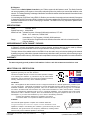
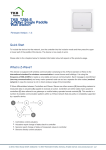
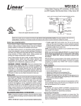
ZRW113
HomePro
RF Home Automation
Z-Wave Radio Frequency (RF) Controlled, 120 VAC,
Isolated Contact Wall Mounted 3-Way Switch,
Series 200, Release 2.2
Shown with supplied
DecoraTM trim plate
Note: This module must be “Included in the Network” only
where it will be permanently installed. The proper operation
of this node in the mesh network is dependent on it knowing its
location with respect to other nodes. You cannot “test bench”
configure this module, then install.
ZRW113 WALL MOUNTED SWITCH
The ZRW113 Isolated Contact Wall Mounted 3-Way Switch is a component of the HomePro lighting control system.
Wire the Wall Mounted Switch in place of the standard wall switch according to the diagram above and program from
the Wireless Controller to operate loads. Inclusion of this Switch on the ZTH100 Wireless Controller menu allows
remote ON/OFF control of lamps connected.
This Wall Mounted Switch is designed to work with other Z-Wave enabled devices. Z-Wave nodes of other types can
be added to the system and will also act as repeaters if they support this function of repeating the signal received to
other modules in the system.
As part of a Z-Wave network, the ZRW113 will also act as a wireless repeater to insure that commands intended for
another device in the network are received. This is useful when the device would otherwise be out of the radio range
of the wireless controller.
There are no field repairable assemblies on this unit.. If service is needed, the unit must be returned where purchased.
DANGER! SHOCK HAZARD.! Read and understand these instructions before installing. This device is intended for
installation in accordance with the National Electric code and local regulations in the United States, or the Canadian
Electrical Code and local regulations in Canada. It is recommended that a qualified electrician perform this installation.
Make sure the load controlled by the switch does not exceed 5540 watts. For indoor use only. Retain instructions
for future use.
INSTALLATION
Wire the ZRW113 in place of a current wall switch according to the diagram above.
When used, AS101’s are required to be wired to the same line (or neutral) which is also wired to the master unit
as well as the load being controlled, and not wired to any other neutral. If multiple neutrals are tied together in one box,
separate the neutrals to preserve the integrity of the ZRW113 circuit. Caution! Do not wire unit “live” (with power on
the circuit) and do not allow the yellow wire to contact line voltage, neutral or ground or you will damage the device.
See the ZTH100 Wireless Controller operating instructions to add this module under the command of the Wireless
Controller.
HomePro
by ADVANCED CONTROL TECHNOLOGIES, INC.
0766-01
1
Z-Wave ZRW 113 Instructions, Series 200, Release 2.2
P/D 011008
INCLUDING ZRW113 TO THE NETWORK
STEP 1.. Prepare the Controller to include a unit to the network by adding it to a group (method of adding a node
to the network). Refer to controller instructions.
STEP 2. The ZRW113 must be in its permanently installed location. Tap either the top or bottom of the
ZRW113 once.
STEP 3. You should see an indication on your Controller that the “DEVICE WAS INCLUDED” in the network.
NOTE: If you have trouble adding the ZRW113 to a group it may be that the Home ID and Node ID were not
cleared from it after testing. You must first “RESET UNIT” with your controller to remove it from the network. If
using the ZTH100, select “MENU”, scroll to “SETUP” and scroll to “RESET UNIT”
Although adding it to a group includes it in the network, removing it from a group does not remove it from the
network. If removed from a group, it functions as a repeater only. “RESET UNIT” removes it completely from
the network.
BASIC OPERATION
(Local Control)
The switch paddle on the ZRW113 allows the user to:
• Include or exclude the module from the Z-Wave system
• Turn on or off the attached load.
• Control other Z-Wave enabled devices “associated” with the ZRW113.
Also, when a controller prompts you to “Send Node ID” or to “Press Button on Unit”, quickly tap the switch on or
off once to satisfy those instructions.
• Tapping top of switch turns the load attached ON.
• Tapping bottom of switch turns the load attached OFF.
• Pressing and holding switch does not effect the load attached but will allow dimming and brightening of
Z-Wave dimmers if associated to the ZRW113 (see below for details).
LED indication
The LED on the ZRW113 will turn on when the load attached is ON. However, the LED can be user configured
to turn ON when the load attached is OFF to act as a night light, if so desired. See ADVANCED OPERATION.
The ZRW113 will flicker its LED when it is transmitting to any of its 2 groups. This can be changed if desired.
See ADVANCED OPERATION.
Auxiliary Switch
The ZRW113 supports the AS101 auxiliary switch to provide 3-way or 4-way operation.
Remote Control
The ZRW113 will respond to BASIC and BINARY commands that are part of the Z-Wave system. Refer to your
controller’s instructions as to whether your controller can transmit those commands.
ADVANCED OPERATION
All On/All Off
The ZRW113 supports the ALL ON/ ALL OFF commands.
The ZRW113 can be set to respond to ALL ON and ALL OFF commands 4 different ways.
Refer to your controller for information on how to set the ZRW113 to operate in the manner you desire. Some
controllers may be only able to set certain settings of ALL ON/ALL OFF response.
The 4 different ways the ZRW113 can be setup to respond to ALL ON and ALL OFF commands are:
1. ZRW113 will not respond to ALL ON or the ALL OFF command.
2. ZRW113 will respond to ALL OFF command but will not respond to ALL ON command.
3. ZRW113 will respond to ALL ON command but will not respond to ALL OFF command.
4. ZRW113 will respond to ALL ON and the ALL OFF command.
Z-Wave ZRW 113 Instructions, Series 200, Release 2.2
P/D 011008
0766-01
2
HomePro
by ADVANCED CONTROL TECHNOLOGIES, INC.
Association
The ZRW113 supports the Association command.
The ZRW113 can be set to control other Z-Wave devices. You can turn on and off, and even dim other Z-Wave devices
once they are “associated” into either of 2 groups of the ZRW113.
Each group is turned on, off or dimmed by tapping or holding the switch a differing amount of times.
If you associate Z-Wave devices into Group 2, you can turn those devices on and off by tapping the switch on or
off twice. You can brighten or dim devices by tapping the switch on or off once and then holding the switch. The load
attached to the ZRW113 is not affected.
If you associate Z-Wave devices into Group 3, you can turn those devices on or off by tapping the switch on or off
three times. You can brighten or dim devices by tapping the switch on or off twice and then holding the switch. The
load attached to the ZRW113 is not affected.
You can associate up to 5 Z-Wave devices into each of these groups.
For instructions on how to “associate” a Z-Wave device into one of these groups, refer to your wireless controller
instructions. (If you are using the ZTH100 controller, refer to the Setup Menu, Association section).
A NOTE ABOUT DIMMING: If you combine Z-Wave enabled dimmers and other types of Z-Wave devices in a group,
place a Z-Wave enabled dimmer into the empty group 1 st to ensure that the dimming operates correctly.
Configuration
The ZRW113 supports the Configuration command.
The ZRW113 can be configured to operate slightly differently than how it works when you first install it. Using the
Configuration command you can configure the following:
You can use a ZTH100 to send Configuration commands. (Refer to the Setup Menu, Configuration section)
Set Ignore Start Level Bit When Transmitting Dim Commands
The ZRW113 can send Dim commands to Z-Wave enabled dimmers. The Dim command has a start level
embedded in it. A dimmer receiving this command will start dimming from that start level if this bit is set to 0.
If the bit is set to 1, the dimmer will ignore the start level and instead start dimming from its current level.
• Parameter No: 1
• Length: 1 Byte
• Valid Values = 0 or 1 (default 1)
Night Light
The LED on the ZRW113 will by default, turn ON when the load attached is turned ON. To make the LED turn
ON when the load attached is turned OFF instead, set parameter 3 to a value of 1.
• Parameter No: 3
• Length: 1 Byte
• Valid Values = 0 or 1 (default 0)
Invert Switch
To change the top of the switch to OFF and the bottom of the switch ON , set parameter 4 to 1.
• Parameter No: 4
• Length: 1 Byte
• Valid Values = 0 or 1 (default 0)
LED Transmission Indication
The ZRW113 will flicker its LED when it is transmitting to any of its 2 groups. This flickering can be set to
not flicker at all (set to 0), to flicker the entire time it is transmitting (set to 1), or to flicker for only 1 second
when it begins transmitting (set to 2). By default, the ZRW113 is set to flicker for only 1 second.
• Parameter 19
• Length: 1 Byte
• Valid Values = 0 , 1, 2 (default 2)
Each Configuration Parameter can be set to its default setting by setting the default bit in the Configuration Set
command. See your controller’s instructions on how to do this (and if it supports it).
All Configuration commands will be reset to their default state when the ZRW113 is RESET from the Z-Wave system.
HomePro
by ADVANCED CONTROL TECHNOLOGIES, INC.
0766-01
3
Z-Wave ZRW 113 Instructions, Series 200, Release 2.2
P/D 011008
SUC Support
There must be a Static Update Controller in your Z-Wave system for this feature to work. The Static Controller
can act as a gateway in the system, since other nodes always know its position (not moved after addition to the
network. The “always listening” advantage of the Static Controller is that other nodes can transmit information frames
to it whenever needed.
You can assign an “SUC Route” to the ZRW113. Refer to your controller’s instructions on how to do this (if it supports
it). Assigning an SUC Route to the ZRW113 allows it to request an update of the Z-Wave devices that are between
it and the Z-Wave device to which it was trying to transmit. The ZRW113 will only request an update when a
transmission fails.
SPECIFICATIONS
Power:
Signal (Frequency):
120 VAC, 60 Hz
908.42 MHz
Maximum Load - Isolated Contacts: 20 amps (5440 watts) maximum, 277 VAC
Motor: 1 H.P. maximum, 120/240 VAC
Incandescent: TV8 (Tungsten), 120 VAC, 960W maximum
Range:
Up to 100 feet line of sight between the Wireless Controller and /or the closest HomePro
Receiver Module
INTEROPERABILITY WITH Z-WAVE™ DEVICES
A Z-Wave™ network can integrate devices of various classes, and these devices can be made by different
manufacturers, just as the ZRW113 can be incorporated into existing Z-Wave™ networks.
The top or bottom of the paddle switch on the ZRW113 can be used to carry out inclusion (adding to the network
by adding to a group), association (operate simultaneously with other nodes), exclusion (remove from a group) or
reset (remove from the network). Controllers can be replicated in order to provide operation from various locations.
WARRANTY
For warranty and general product information visit our web site at www.act-solutions.com
ABOUT ZRW113’S CERTIFICATION
The ZRW113 is certified to comply with applicable FCC and IC rules and
regulations governing RF and EMI emissions.
This device complies with part 15 of the FCC Rules. Operation is subject
to the following two conditions: (1) This device may not cause harmful
interference, and (2) This device must accept any interference received,
including interference that may cause undesired operation.
FCC NOTICE
Note: This equipment has been tested and found to comply with the limits for a Class B digital device, pursuant to part
15 of the FCC Rules. These limits are designed to provide reasonable protection against harmful interference in a
residential installation. This equipment generates, uses, and can radiate radio frequency energy and, if not installed
and used in accordance with the instructions may cause harmful interference to radio communications. However,
there is no guarantee that interference will not occur in a particular installation. If this equipment does cause harmful
interference to radio or television reception, which can be determined by turning the equipment off and on, the user is
encouraged to try to correct the interference by one or more of the following measures:
- Increase the separation between the equipment and receiver.
- Consult the dealer or an experienced radio/TV technician for help.
IC NOTICE
This Class B digital apparatus complies with Canadian ICES-003.
Cet appareil numérique de la classe B est conforme à la norme NMB-003 du Canada.
Operation is subject to the following two conditions: (1) this device may not cause
interference, and (2) this device must accept any interference, including interference that may cause undesired operation of the device.
Z-Wave ZRW 113 Instructions, Series 200, Release 2.2
P/D 011008
0766-01
4
HomePro
by ADVANCED CONTROL TECHNOLOGIES, INC.