1
®
ST
TE
&
LE ER
DU EST
MO R T
N
O
TIO NS
NI SE
IG INE
G
EN
H
HIG
FF
W
RO
LO
WE
PO
H
RIC
t
lec
Se W,
LO TS
L
VO
AN
LE
E
NG
RA
S
LT
VO
Y
MS
NC
OH QUE
E
FR
N
TIO
NC
FU
PU
LS
E
PO
WE
R
9V
.
.
ON
.
DS
IGH LEA HT IS
O H LL
IG
ET TA RL
T
NG EC HE
RA NN OT
ET CO AN
N
MO T: 1) S3) DIS AK IF
M
E
ES S. . W
CO
Y T HM ON
ER TO O T IS
TT
L
H
NA 9V BACTIONT LIG
SIG
UN ES
TF TT
SE OS
2) PM
TO
. IF
O.K
G
RIG
ER
CP9087
TM
PROFESSIONAL
Vehicle
Service
Info
The following publishers have manuals containing diagnostic information for
electronic engine control and ignition systems. Contact the publishers for
availability and pricing, specifying the make, model and year of your vehicle.
Some manuals may be available at auto parts stores or your local public library.
Vehicle Service Manuals
Chilton Book Company
Chilton Way
Radnor, PA 19089
Haynes Publications
861 Lawrence Drive
Newbury Park, CA 91320
Cordura Publications
Mitchell Manuals, Inc.
Post Office Box 26260
San Diego, CA 92126
Motor’s Auto Repair Manual
Hearst Company
250 W. 55th Street
New York, NY 10019
Suitable manuals have titles such as:
“Electronic Engine Controls”
“Fuel Injection and Feedback Carburetors”
“Fuel Injection and Electronic Engine Controls”
“Emissions Control Manual”
... or similar titles.
Vehicle Service
Manuals from General
Motors Corporation
Vehicle Service
Manuals from Ford
Motor Company (Ford,
Lincoln, Mercury)
Vehicle Service
Manuals from Toyota,
Honda, Nissan
Buick, Cadillac,
Chevrolet, GEO, GMC,
Oldsmobile & Pontiac
Helm Incorporated
Post Office Box 07130
Detroit, MI 48207
Ford Publication Dept.
Helm Incorporated
Post Office Box 07150
Detroit, MI 48207
Toyota Motor Corporation
Toyota Service Publications
750 W. Victoria Street
Compton, CA 90220-5538
Vehicle Service
Manuals from Chrysler
Corporation
Honda Motor Co., Ltd.
Helm Incorporated
Post Office Box 07280
Detroit, MI 48207
Saturn
Adistra Corporation
c/o Saturn Publications
101 Union Street
Post Office Box 1000
Plymouth, MI 48170
Chrysler Corporation
Dyment Distribution Service
Post Office Box 360450
Strongsville, OH 44136
Nissan North America, Inc.
Dyment Distribution Service
c/o Nissan
20770 Westwood Drive
Strongsville, OH 44136
Index
Section
1
2
3
4
Vehicle Service Information ...................... Inside front cover
Safety Precautions ............................................................... ii
Tester Basics ............................................. 1-1
Testing Sensors .......................................... 2-1
• Troubleshooting Tips .......................................... 2-1
• Engine Coolant Temperature .............................. 2-2
• Inlet Air Temperature .......................................... 2-3
• Throttle Position (TP) .......................................... 2-6
• EGR Valve Position (EVP) ................................ 2-14
• Oxygen .............................................................. 2-18
• Engine Knock .................................................... 2-26
• Manifold Absolute Pressure (MAP/BARO) ....... 2-28
• Mass Air Flow (MAF) ........................................ 2-34
• Vane Air Flow .................................................... 2-40
• Crankshaft/Camshaft Position .......................... 2-46
Magnetic Reluctance Type ......................... 2-49
Hall Effect or Optical Type .......................... 2-51
Testing Ignition Modules ............................3-1
More Uses for the Sensor Probe ............... 4-1
• "Circuit Tester" Voltage Check ........................... 4-1
• Continuity Checks ............................................... 4-2
• Diode Check ........................................................ 4-4
i
Safety
First
General Safety Guidelines to Follow When
Working on Vehicles
• Always wear approved eye protection
• Always operate the vehicle in a well-ventilated area. Do not inhale exhaust
gases – they are very poisonous!
• Always keep yourself, tools, and test equipment away from all moving or hot
engine parts.
• Always make sure the vehicle is in Park (automatic transmission) or Neutral
(manual transmission) and that the parking brake is firmly set. Block the drive
wheels.
• Never lay tools on vehicle battery. You may short the terminals together,
causing harm to yourself, the tools, or the battery.
• Never smoke or have open flames near vehicle. Vapors from fuel or charging
batteries are highly flammable and explosive.
• Never leave vehicle unattended while running tests.
• Always keep a fire extinguisher suitable for all types of fires handy.
• Always turn ignition key OFF when connecting or disconnecting electrical
components, unless otherwise instructed.
• Use shop rags to cover fuel line fittings when connecting or disconnecting fuel
lines. Avoid contact with fuel. Dispose of all rags properly.
• Clean up all fuel spills immediately.
• Keep away from engine cooling fan. On some vehicles, the fan may start up
unexpectedly.
• You must follow vehicle service manual cautions when working around the air
bag system. If the cautions are not followed, the air bag may open unexpectedly, resulting in personal injury. Note that the air bag can still open up several
minutes after the ignition key is turned OFF (or even if the battery is disconnected) because of a special energy reserve module.
• Always follow vehicle manufacturer’s warnings, cautions, and service procedures.
ii
6-3
Section
1
Tester
Basics
— Description of Controls and Accessories
— Installing and Checking the 9 Volt Battery
Note: Detailed procedures for testing sensors and ignition modules are
located in Section 2 (sensors) and Section 3 (ignition modules).
1
RANGE
Switch
Controls power to the Tester and selects measurement range sensitivity (as required by various
sensor tests).
• POWER OFF - No power supplied to either the
tester or RED test lead.
• LOW - Tester powered up for use. Voltage from
9 volt battery supplied to RED test lead. Selects
range for measuring low levels of voltage,
resistance or frequency.
• HIGH - Tester powered up for use. Voltage from
9 volt battery supplied to RED test lead. Selects
range for measuring higher levels of voltage,
resistance or frequency.
2
FUNCTION
Switch
Selects the type of signal being measured (for
conducting sensor and ignition module tests). Different
kinds of signals are used by various sensors.
• VOLTS - Measures voltages. This function is used
to test most sensors.
• OHMS - Measures resistance. Also used for
checking continuity and testing diodes (see section
4). Mostly used for testing temperature sensors.
• FREQUENCY - Measures frequency signals.
(Peak signal voltage must be at least 3 volts
to register.) Some MAP and MAF sensors
send a frequency signal. This function is
also used to test ignition modules.
1-1
Section 1
3
TEST
Lights
A single TEST light turns on to show the level of a measured signal
(voltage, resistance or frequency). When signal values are low, the
TEST light is off or near the bottom of the column. The TEST light
moves higher up the column as the signal level increases.
Sensor tests involve working the sensor and watching the TEST
light move up, down or flash. Note that the motion of the light is
more important than its actual position.
4
PULSE
Light
Used when testing ignition modules. The PULSE light will flash
if the module is good.
5
RICH/
LEAN
Lights
These lights are active when the tester switches are set to LOW
VOLTS only.
6
Test
Leads
Note that the PULSE light will also be on (or flash) whenever
frequency signals are being measured - this is normal.
• LEAN (green): ON for voltages between 0.1 and 0.59 volts.
• RICH (red): ON for voltages above 0.6 volts.
The RICH/LEAN lights work along with the TEST lights and are
helpful when testing oxygen sensors. The RICH/LEAN lights may be
ignored when testing other sensors using the LOW VOLTS range.
Two or more of these are used for the various tests and checks.
Yellow - The SIGNAL lead. Signals probed by this lead cause
the TEST lights to react. Usually connected to a sensor or
ignition module output circuit during testing.
Black - The COMMON lead. Used as a circuit ground or signal
reference point for all tests and checks. This lead is always
used.
Green - The TRIGGER lead. Used when testing ignition
modules. Sends a signal to “fire” the module. Usually connected
to the module crankshaft/camshaft input circuit.
1-2
Red - The 9V power lead. This lead is connected to the 9 volt
battery inside the tester whenever the RANGE switch is in the
LOW or HIGH positions. Ignition modules and some sensors
require this power for testing.
Tester Basics
6
IGNITION MODULE &
ENGINE SENSOR TESTER
TEST
3
HIGH
1
LOW
POWER OFF
5
RICH
RANGE
Select
LOW,
VOLTS
LEAN
VOLTS
2
OHMS
FREQUENCY
FUNCTION
PULSE
7
4
SIGNAL
COMMON
TRIGGER
POWER 9V
9V BATTERY TEST: 1) SET RANGE TO HIGH.
2) SET FUNCTION TO OHMS. 3) DISCONNECT ALL LEADS.
O.K. IF TOPMOST TEST LIGHT IS ON. WEAK IF ANOTHER LIGHT IS ON.
8
9
7
Backprobe
Adapter
To Sensor
Allows test lead to probe sensor circuits when the sensor is
connected to vehicle wiring harness.
• Slide the “scooped” end of adapter next to circuit wire
entering rear of connector.
• Continue pushing adapter until it touches terminal inside
connector. (Slightly twisting adapter while pushing may
ease entry)
• Grasp open end of adapter with test lead clip. Keep
pushing on adapter to maintain circuit contact.
Caution: The “scooped” end of the
adapter will break if you bend it.
To Computer
1-3
Section 1
Tester Basics
8
Jumper Lead
Used when checking some ignition modules. Makes
extra connections as required for testing.
9
Connector
Pin Adapters
Used for easier attachment of test leads to certain
sensor or wiring connector pins.
• Push one end of the adapter onto the desired
connector pin.
• Grasp the other end with the test lead clip.
Sensor
Tester
Power
A 9-volt transistor radio battery must be installed to
power the unit. Use an alkaline battery (conventional
batteries are too weak for ignition module testing).
Installing the Battery
1. Hold the tester face down with both hands.
2. Using both thumbs, firmly press downwards and
outwards on the battery compartment door at the
bottom of the tester.
3. Slide the battery compartment door away from the
tester to remove.
9V
4. Attach battery to connector and install inside
compartment.
5. Replace battery door. Slide door inwards until it
snaps closed.
Checking the Battery
HIGH
LOW
POWER OFF
RANGE
VOLTS
OHMS
FREQUENCY
FUNCTION
TEST
1. Make sure none of the test leads are connected
together or touching anything.
2. Set RANGE switch to HIGH.
3. Set FUNCTION switch to OHMS.
4. Battery is good if the top TEST light is ON. If any light
below the top TEST light is ON, the battery is too
weak for reliable testing and should be replaced.
TIP: To extend battery life, always switch to POWER
OFF when not making a measurement. This is safe to
do even if the tester is connected to a circuit.
1-4
Section
Section2
2
Troubleshooting
Tips
Testing Sensors
Save yourself time! Always begin with a thorough
visual and “hands-on” inspection. You can often
find the cause of many problems by just looking.
• Has the vehicle been serviced recently?
Sometimes things get reconnected in the wrong
place, or not at all.
• Don’t take shortcuts. Inspect hoses and wiring
which may be difficult to see due to location.
• Inspect the air cleaner and ductwork for defects.
• Check sensors and actuators for damage.
YST
• Inspect all vacuum hoses for:
HVAC
CRUISE
CE BOOSTER
G GAP
U.S.A.
EM
EGR
VAC
REG
BRAKE BOOSTER
FUEL
PRESS
REG.
TO TRANS
MODE
EGR
VAC
REG
FRONT
OF CAR
12RAC8
– Correct routing. Refer to vehicle service
manual, or Vehicle Emission Control Information
(VECI) decal located in the engine compartment.
– Pinches and kinks.
– Splits, cuts or breaks.
• Inspect wiring for:
– Contact with sharp edges (this happens often).
6D
LC
24
– Contact with hot surfaces, such as exhaust
manifolds.
– Pinched, burned or chafed insulation.
– Proper routing and connections.
• Check electrical connectors for:
– Corrosion on pins.
5A
AC
28
– Bent or damaged pins.
– Contacts not properly seated in housing.
– Bad wire crimps to terminals.
2-1
Section 2 Engine TEMPERATURE
HIGH
SENSOR
RESISTANCE
LOW
Cold
Typical Engine Coolant
Temperature Sensor
What is It?
Hot
TEMPERATURE
The engine temperature sensor is a thermistor - a
resister whose resistance changes with temperature. The hotter the sensor gets, the lower the
resistance becomes. The thermistor is mounted
inside the tip of a threaded metal housing. This is a
2-wire sensor. (Exception: some Chrysler engines
have a dual sensor with three wires.)
How is It
Used?
The computer needs to know engine temperature
so it can modify air/fuel ratios, spark advance, idle
speed, and emission device operation (such as an
EGR valve).
Location
The sensor is usually threaded into the engine
block, lower intake manifold, or cylinder head to
provide direct contact with coolant.
When to Test
• Related trouble codes sent by computer.
• Driveability problems such as hard starting,
rough idle, stalling, hesitation, stumble, surging,
knocking (pinging), poor fuel economy, or black
exhaust smoke.
What to
Inspect
2-2
Sensor operation (see test on page 2-4). Poor
connections at sensor or computer. Faulty sensor
wiring (open or short circuits). Heavy deposits on
sensor tip which can cause poor response.
Leakage into sensor housing. Engine running too
hot (problems with antifreeze, thermostat, water
pump, fan, belts, low engine oil).
Air TEMPERATURE
HIGH
SENSOR
RESISTANCE
LOW
Cold
Typical Air Temperature Sensor
What is It?
Hot
TEMPERATURE
The air temperature sensor is a thermistor - a
resister whose resistance changes with temperature.
The hotter the sensor gets, the lower the resistance
becomes. The thermistor is mounted inside the tip of
a threaded metal housing. This is a 2-wire sensor.
How is It
Used?
The computer needs to know air temperature to
calculate the amount of air entering the engine.
Then, the computer can provide the proper air/fuel
mixture for the desired operating condition.
Location
The sensor is threaded into the intake manifold,
throttle body, rear of air cleaner assembly or
elsewhere along the path of air entering the
engine. Sometimes this sensor is built into a vane
airflow meter or mass airflow sensor assembly.
One connector handles both the air flow and
temperature sensor circuits.
When to Test
• Related trouble codes sent by computer.
• Driveability problems such as hard starting,
rough idle, stalling, hesitation, stumble, surging,
poor fuel economy, or black exhaust smoke.
What to
Inspect
Sensor operation (see test on page 2-4). Poor
connections at sensor or computer. Faulty sensor
wiring (open or short circuits). Heavy deposits on
sensor tip which can cause poor response.
Restricted or blocked air passageways.
Engine running too hot (problems with
antifreeze, thermostat, water pump, fan, belts,
low engine oil).
2-3
Section 2 Testing Sensors
Temperature Sensor Test Procedure
Use this procedure for testing all engine coolant or inlet air temperature sensors.
Exceptions:
• Certain Toyota, Nissan and Ford engines using vane airflow sensors have the
air temperature sensor built into the vane airflow assembly. Refer to page 2-40
for testing.
• GM 1988 2.8L Mass Airflow Sensor (5 pin only) also has a built-in air temperature sensor. Use same test procedure as for vane airflow temperature sensor.
Refer to page 2-34 for testing.
Sensor may be tested on or off vehicle.
Warning: On-car testing involves running engine. Observe all safety precautions
(see page ii). Work in well ventilated area.
1) Verify ignition key is OFF.
Allow engine to cool to outside temperature before testing.
2) Check Tester battery
Refer to page 1-4. Set RANGE switch to POWER OFF
when done.
3) Disconnect wiring harness from sensor - Inspect for
damage.
Some vehicles use a metal snap ring to secure wiring
harness to sensor. Remove this snap ring before disconnecting wiring harness.
4) Off-Car testing only: Remove sensor.
Be careful of coolant spillage from mounting hole if
removing engine temperature sensor.
5) Connect test leads.
• YELLOW to either sensor pin.
• BLACK to remaining sensor pin.
Yellow
2-4
Black
Engine Air TEMPERATURE
6) Verify test clips make good contact and do not touch each
other.
HIGH
Make sure red and green test clips are not touching anything.
LOW
POWER OFF
7) Set RANGE switch to HIGH.
RANGE
VOLTS
8) Set FUNCTION switch to OHMS.
OHMS
FREQUENCY
9) Note TEST light position on tester.
FUNCTION
If the sensor is good, the light will move downwards as the
sensor heats up.
10) On-Car test only: Disconnect test leads and reconnect
sensor to vehicle wiring harness.
11) Heat sensor tip thoroughly.
On-Car test: Start engine and idle at 2000 RPM until upper
radiator hose is hot.
Off-Car test:
– Dip sensor tip into boiling water, OR...
– (metal sensor housing) Heat tip with flame from candle or
cigarette lighter OR...
– (plastic sensor housing) Heat tip with hair dryer.
12) On-Car test only: Turn ignition key OFF. Disconnect
vehicle wiring harness from sensor and reconnect test
leads as before.
13) Observe TEST light position for test results.
• Good Sensor - TEST light moved downwards below original
position. (TEST light may go off if sensor is very hot - this is
OK.) The TEST light will move upwards as the sensor cools
off. Range of TEST light movement varies with sensor type
and temperature change.
• Bad Sensor - TEST light position did not change during test.
14) Testing is complete.
Set RANGE switch to POWER OFF and remove all test
leads.
2-5
Section 2 Testing Sensors
TYPICAL THROTTLE POSITION SENSORS
HIGH
What
is It?
Throttle Position Sensor
SIGNAL
The throttle position sensor is a
VOLTAGE
potentiometer - a type of variable
resistor (similar to a dashboard
dimmer control). These sensors come
LOW
in a wide variety of styles - some with
MIN.
MAX.
ROTATION
connectors at the end of a short wire
“pigtail”. The computer supplies power
and ground to the sensor. The sensor has an element which is
turned (rotary type) or pushed (linear type). When the sensor is
mounted on the engine, the element is linked to the throttle so
they move together. The sensor sends a voltage signal back to
the computer indicating element (and thus throttle) position. The
voltage signal increases when the throttle opens and operates
the sensor element. Throttle position sensors on Asian vehicles
may also include one or two throttle position switches.
Throttle Position Switch
This is one or two switches usually built into a single housing
(often resembling a throttle position sensor). Movement of the
throttle linkage operates the throttle switches. The switches are
wired to the computer. The computer usually supplies an
ground connection to one side of each switch.
2-6
• The idle position switch is closed (or open - depends upon
vehicle) when the throttle is resting. The switch operates
when the throttle is opened (by any amount) and no longer in
the idle position.
THROTTLE POSITION Sensor/Switch
• Sometimes a second switch is used to signal a wide
open throttle condition. This switch is normally open (or
closed - depends upon vehicle) when the throttle is at
idle or just partially open. The switch operates when the
throttle is opened beyond a certain point. (The amount of
throttle opening required to operate the switch varies
with vehicle.)
How it is
used?
The computer uses throttle position to determine engine
operating condition: idle (closed throttle), cruise (part
throttle), or hard acceleration (wide open throttle). The
computer can then properly control air/fuel mixtures, spark
advance, idle speed, and lock-up torque converters.
Location
Fuel injected engines: Rotary type sensor - usually
mounted to outside of throttle body and linked to throttle
shaft.
Computer controlled carburetor engines: Linear (sliding)
type - usually mounted inside carburetor (GM) or outside
carburetor (Ford).
When to
Test
What to
Inspect
• Related trouble codes sent by computer.
• Driveability problems such as hard starting, rough idle,
stalling, hesitation, stumble, surging, knocking (pinging),
poor fuel economy, backfiring, no torque converter lock-up.
Sensor operation (see test on page 2-10) or switch
operation (see test on page 2-12). Poor connections at
sensor or computer. Sensor position adjustment. Faulty
sensor wiring (open or short circuits). Binding throttle shaft
or linkage. If used: “Cruise Control” linkage problems, idle
speed control motor, vacuum hose connected to throttle
positioner, choke, or cam systems affecting throttle
position.
2-7
Section 2 Testing Sensors
Throttle Position Sensor Connectors
A
B
= Test A, page 2-10
Some sensors require more than one test.
= Test B, page 2-12
Note: If the Red and Black test lead hook-ups are reversed,
the TEST light will move in the opposite direction during Test A.
This does not affect the accuracy of the test or harm the sensor.
GM
FORD
Black
Red
Yellow
Black
A
A
Yellow
Red
GM, FORD, CHRYSLER, HONDA
FORD
Black
Yellow
A
Yellow
A
Red
Black
Red
HONDA
HONDA
HONDA
Yellow
A
Black
Red
A
Black
Red
A
Black
Yellow
Refer to vehicle service manual for connectors
not shown. Hook up as follows:
• Red test lead to sensor power pin
• Yellow test lead to sensor signal pin
2-8
• Black test lead to sensor ground pin
Red
Yellow
THROTTLE POSITION Sensor/Switch
TOYOTA
TOYOTA/NISSAN
A
B
Red Yellow Black
B
Yellow Black
B
Yellow Black
Not used on some
vehicles. Perform this
test only if vehicle
Black Yellow mating connector has
3 wires.
A
Red
Yellow
Black
Yellow
B
Some sensors have
cable attached here.
Testing is identical.
Black
Black
Yellow
Not used on some
vehicles. Perform
this test only if
vehicle mating
connector
has 3 wires.
B
2-9
Section 2 Testing Sensors
TEST A - Throttle Position Sensor
Important: If more than one hook-up is shown, it means more than one test is
required to check all parts of the sensor. Do all tests shown for your sensor.
The letter next to the hook-up refers to the test procedure.
Sensor may be tested on or off vehicle. (Exception: On-car test only for most
Honda - sensor permanently attached to throttle body.)
Warning: Observe all safety precautions (see page ii) if testing sensor on
vehicle.
1) Verify ignition key is OFF.
2) Check Tester battery
Refer to page 1-4. Set RANGE switch to POWER OFF when
done.
3) Disconnect wiring harness from sensor - Inspect for
damage.
Some vehicles use a metal snap ring to secure wiring harness
to sensor. Remove this snap ring before disconnecting wiring
harness.
4) Off-Car testing only: Remove sensor.
IMPORTANT: Many throttle position sensors require special
adjustment when reinstalled. Refer to vehicle service manual
for adjustment procedure. A good sensor will not perform
properly if incorrectly adjusted.
5) Connect test leads.
Connect TEST leads according to diagram A in the component drawing.
6) Verify test clips make good contact and do not touch
each other.
Make sure unused clips are not touching anything.
2-10
THROTTLE POSITION Sensor/Switch
7) Honda only: 1988-92 Civic and CRX
– Remove vacuum hose from dashpot diaphragm.
– Apply 20 in. Hg to the dashpot diaphragm using a hand
vacuum pump.
HIGH
LOW
– The dashpot diaphragm is part of the throttle body
assembly. It is used to control cold engine fast idle and
throttle closure speed so engine will not stall.
POWER OFF
RANGE
VOLTS
OHMS
FREQUENCY
FUNCTION
8) Set RANGE switch to HIGH.
9) Set FUNCTION switch to VOLTS.
10) Operate sensor - Watch TEST light for results.
(Note: TEST light may be on or off before sensor is
operated.)
On-Car test: Slowly move throttle linkage back and forth from
idle to wide open position.
Off-Car test: Slowly rotate sensor element back and forth
from end to end.
• Good Sensor - TEST light smoothly moves up or down as
sensor is operated. (The TEST light may go off if it moves
to the bottom of the column - this is O.K.) Range of TEST
light movement varies with sensor type and vehicle
mounting.
• Bad Sensor - TEST light position does not change during
test OR light movement is erratic, showing a sudden jump
or dip during smooth sensor operation.
11) Testing is complete.
Set RANGE switch to POWER OFF and remove all test
leads.
2-11
Section 2 Testing Sensors
TEST B - Throttle Position Switch
Important: If more than one hook-up is shown, it means more than one test is
required to check all parts of the switch. Do all tests shown for your switch. The
letter next to the hook-up refers to the test procedure.
Switch may be tested on or off vehicle.
Warning: Observe all safety precautions (see page ii) if testing sensor on
vehicle.
1) Verify ignition key is OFF.
2) Check Tester battery
Refer to page 1-4. Set RANGE switch to POWER OFF when
done.
3) Disconnect wiring harness from switch - Inspect for
damage.
Some vehicles use a metal snap ring to secure wiring
harness to switch. Remove this snap ring before disconnecting wiring harness.
4) Off-Car testing only: Remove switch.
IMPORTANT: Many throttle position switches require special
adjustment when reinstalled. Refer to vehicle service manual
for adjustment procedure. A good switch will not perform
properly if incorrectly adjusted.
5) Connect test leads.
Connect TEST leads according to diagram B in the component drawing.
6) Verify test clips make good contact and do not touch
each other.
Make sure unused clips are not touching anything.
2-12
THROTTLE POSITION Sensor/Switch
HIGH
LOW
POWER OFF
7) Set RANGE switch to HIGH.
RANGE
VOLTS
OHMS
FREQUENCY
8) Set FUNCTION switch to OHMS.
9) Operate sensor - Watch TEST light for results.
FUNCTION
On-Car test: Slowly move throttle linkage back and forth
from idle to wide open position.
Off-Car test: Slowly rotate sensor element back and forth
from end to end.
TEST
TEST
• Good Switch - TEST light switches between
being ON at top of column and OFF
• Bad Switch - TEST light always ON at top of
column or always OFF.
10) Testing is complete.
Set RANGE switch to POWER OFF and
remove all test leads.
2-13
Section 2 Testing Sensors
FORD
EGR Valve
What is it?
HIGH
SENSOR
VOLTAGE
LOW
MIN.
HONDA
EGR Valve
This sensor is a potentiometer - a type of variable
resistor (similar to a dashboard light dimmer
control). The computer supplies power and ground
to the sensor. the sensor has a shaft which is
pushed. When the sensor is mounted on the EGR
valve, the shaft gets pushed as the valve opens.
The sensor sends out a voltage signal indicating
the amount of valve opening (“lift”). The voltage
signal gets larger the more the valve is opened.
MAX.
VALVE OPENING
How it is
used?
The computer is programmed to provide optimum
EGR flow during idle, cruise, and hard acceleration
operating conditions. The computer uses the
sensor signal to calculate actual EGR flow. Then
the computer can modify the EGR valve opening
as required.
Location
Attached to the top of the EGR valve.
When to Test
• Related trouble codes sent by computer.
• Driveability problems such as hesitation,
stumble, surging, poor fuel economy, erratic
acceleration, knocking (pinging), no torque
converter lock-up.
What to
Inspect
2-14
Sensor operation (see page 2-15). Poor connections at the sensor or computer. Damaged or
sticking EGR valve. Worn or broken vacuum
hoses, vacuum connectors. Damaged vacuum
reservoir, canister. Problems with control solenoids
supplying operating vacuum to open EGR valve.
EGR Valve Position/Lift Sensors
EGR Valve Position Sensor Test Procedure
Sensor may be tested on or off vehicle.
Warning: Observe all safety precautions (see page ii) if testing sensor on
vehicle.
1) Verify ignition key is OFF.
2) Check Tester battery
Refer to page 1-4. Set RANGE switch to POWER
OFF when done.
3) Disconnect wiring harness from sensor - Inspect
for damage.
Some vehicles use a metal snap ring to secure
wiring harness to sensor. Remove this snap ring
before disconnecting wiring harness.
4) Off-Car testing only: Remove sensor.
Note: Some sensors are permanently attached to
the EGR valve and cannot be removed.
5) Connect test leads according to diagram.
6) Verify test clips make good contact and do not
touch each other.
HIGH
Make sure unused clips are not touching anything.
LOW
POWER OFF
7) Set RANGE switch to HIGH.
RANGE
VOLTS
OHMS
FREQUENCY
FUNCTION
8) Set FUNCTION switch to VOLTS.
9) Operate sensor - Watch TEST light for results.
(Note: TEST light may be on or off before sensor is
operated.)
On-Car test:
– Remove vacuum control hose from EGR valve.
– Connect hand vacuum pump to EGR valve.
– Gradually apply vacuum to slowly open valve.
2-15
Section 2 Testing Sensors
Off-Car test: Slowly push sensor element back and forth
from end to end.
• Good Sensor - TEST light smoothly moves up or down as
sensor is operated. (The TEST light may go off if it moves
to the bottom of the column - this is O.K.) Range of TEST
light movement varies with sensor type and vehicle
mounting.
• Bad Sensor - TEST light position does not change during
test OR light movement is erratic, showing a sudden jump
or dip during smooth sensor operation.
10) Testing is complete.
Set RANGE switch to POWER OFF and remove all test
leads.
2-16
EGR Valve Position/Lift Sensors
Sensor Connectors
Note: If the Red and Black test lead hook-ups are reversed,
the TEST light will move in the opposite direction during the
test. This does not affect the accuracy of the test or harm
the sensor.
Black
FORD
Black
Yellow
Red
HONDA – #1
HONDA – #2
Yellow
Red
Yellow
Black
Red
Honda uses two
sensor types. Try
hook-up #1 first.
If good test
results are not
obtained, retest
using hook-up #2
before judging
sensor.
Refer to vehicle service manual for connectors
not shown. Hook up as follows:
• Red test lead to sensor power pin
• Yellow test lead to sensor signal pin
• Black test lead to sensor ground pin
2-17
Section 2 Testing Sensors
Typical Oxygen Sensor
What is It?
The oxygen sensor is a zirconium dioxide ceramic
mounted in the tip of a threaded metal housing.
The tip is perforated to protect the sensing element
but still allow exhaust gases to pass through.
The sensor produces a voltage signal based on the
amount of oxygen it contacts. A low voltage
indicates a lean exhaust (too much oxygen). A
higher voltage signals a rich exhaust (not enough
oxygen).
The sensor must be very hot to operate: 349(C
(660(F). Many have 2-wire heating elements builtin to quicken the warm-up time.
2-18
How it is
used?
The computer uses this sensor to calculate
optimum air/fuel mixture for low emissions and
good fuel economy. If the sensor indicates a rich
exhaust (not enough oxygen because of too much
fuel), the computer will compensate by reducing
fuel delivery. If the computer receives a lean signal
(too much oxygen because of too little fuel), it will
increase fuel delivery. NOTE: Some vehicles use
more than one oxygen sensor.
Location
The sensor is threaded into the exhaust manifold to
give it direct contact with the exhaust gases.
OXYGEN
HIGH
SENSOR
VOLTAGE
LOW
Lean
OPTIMUM
Rich
AIR FUEL MIXTURE
When to Test
• Related trouble codes sent by computer.
• Driveability problems such as rough running,
hesitation, stumble, poor fuel economy, poor
performance, black exhaust smoke.
Inspection
Sensor operation (see page 2-21). Poor connections at the sensor or computer.
This sensor often fails because of contamination
from fuel, oil additives, gasket sealer or an overly
rich running engine. Factors which can make a rich
running engine include: ignition system problems
(coil, distributor cap, rotor, spark plugs, wires), fuel
contaminated by engine oil, emission devices
(carbon canister, EGR valve, PCV valve, air
injection system), manifold leaks, air filter, fuel
pressure and engine not at normal operating
temperature.
IMPORTANT:
Some engines (usually off-road applications)
use a titania-type oxygen sensor. This sensor
resembles the common zirconium type, but has
an open-ended tip. The titania sensor changes
resistance when it operates. This tester is
not designed to test the titania type
sensor.
2-19
Section 2 Testing Sensors
Sensor Types
1-Wire: Single wire goes to sensor SIGNAL.
Sensor housing is connected to sensor GROUND.
2-Wire: One wire goes to sensor SIGNAL. Second
wire goes to sensor GROUND. Refer to vehicle
service manual for wire identification. (Sensor wire
is often black.)
3-Wire: Two wires (often the same color) go to the
sensor heating element. Third wire (different color
from the others) goes to sensor SIGNAL. Sensor
housing is connected to sensor GROUND.
4-Wire: Two wires (often the same color) go to the
sensor heating element. Third wire goes to sensor
SIGNAL. Fourth wire goes to sensor GROUND.
Refer to vehicle service manual for wire identification. (Signal wire is often black.)
2-20
OXYGEN
Heating Element Test
• Do this test if sensor has a heating element (3 or 4 wire connector).
• If sensor has 1 or 2 wire connector, do not do this test. Go directly to On-Car
Test (page 2-22).
Warning: Observe all safety precautions (see page ii) if testing sensor on vehicle.
1) Verify ignition key is OFF.
2) Check Tester battery
Refer to page 1-4. Set RANGE switch to POWER OFF when done.
3) Disconnect wiring harness from sensor - Inspect for damage.
Some vehicles use a metal snap ring to secure wiring harness to
sensor. Remove this snap ring before disconnecting wiring
harness.
4) Connect test leads.
• YELLOW to either sensor HEATER pin.
• BLACK to remaining sensor HEATER pin.
HIGH
LOW
POWER OFF
5) Verify test clips make good contact and do not touch each
other.
Make sure unused clips are not touching anything.
RANGE
VOLTS
6) Set RANGE switch to HIGH.
OHMS
FREQUENCY
7) Set FUNCTION switch to OHMS.
FUNCTION
TEST
8) Observe TEST light for test results.
• Good Heater: TEST light OFF (low resistance).
• Bad Heater: TEST light ON in any position (resistance too
high, or open circuit).
9) Heating Element test is complete.
• Set RANGE switch to POWER OFF and remove all test leads.
• Go to On-Car Test.
2-21
Section 2 Testing Sensors
On-Car Test
Important: Reliable testing of the oxygen sensor while on-vehicle is very
difficult because test conditions cannot be well controlled. If the sensor
responds during on-car testing, then it is probably good and no other
testing is necessary. If the sensor does not seem to respond when tested
on-car, remove it and perform the off-car test before deciding whether or
not the sensor is bad.
Warning: This test involves running the engine. Observe all safety precautions
(see page ii). Work in well-ventilated area.
1) Verify ignition key is OFF.
2) Check Tester battery
Refer to page 1-4. Set RANGE switch to POWER OFF
when done.
3) Connect test leads.
• YELLOW to sensor SIGNAL circuit.
• BLACK to good vehicle GROUND.
– Keep sensor connected to vehicle wiring and use
backprobe adapter to contact sensor SIGNAL circuit if
possible.
– If you cannot use backprobe, disconnect sensor
connector and connect YELLOW test lead directly to
sensor SIGNAL pin. Note: Most computer systems will
store a trouble code in memory (and turn on the “Check
Engine” light) if engine is run with sensor disconnected.
Ignore or erase the code after testing. Refer to Vehicle
Service Manual.
4) Verify test clips make good contact.
HIGH
LOW
Make sure unused clips are not touching anything.
POWER OFF
RANGE
5) Set RANGE switch to LOW.
VOLTS
OHMS
6) Set FUNCTION switch to VOLTS.
FREQUENCY
FUNCTION
2-22
7) Start engine - Idle until hot.
Run engine until upper radiator hose is hot and
pressurized.
OXYGEN
8) Observe RICH/LEAN lights during fast idle.
• The TEST light column also indicates sensor voltage,
but it is easier to check operation by watching the RICH/
LEAN lights.)
• Maintain throttle partially open (2000 RPM idle).
– IF the RICH/LEAN lights flash back and forth every 3
seconds or less...
THEN the sensor is good and no further testing is
necessary. Go to step 10.
– IF it takes longer than 3 seconds for the RICH/LEAN
lights to switch back and forth...
THEN the sensor may be degraded. Go to step 10,
then do the Off-Car test on page 2-24
– IF the RICH/LEAN lights do not flash back and forth...
THEN go to step 9.
9) Observe RICH / LEAN lights during throttle changes.
• Quickly move throttle from idle to partially open (2000
RPM) position then back to idle. (This attempts to create
a momentary rich or lean engine operating condition.)
Repeat this throttle action several times while observing
the RICH/LEAN lights.
RICH
LEAN
RICH
LEAN
– IF the RICH/LEAN lights switch within 3 seconds of the
throttle action...
THEN the sensor is good and no further testing is
necessary. Go to step 10.
– IF it takes longer than 3 seconds for the RICH/LEAN
lights to switch...
THEN the sensor may be degraded. Go to step 10. Do
the Off-Car test on page 2-24
– IF the RICH/LEAN lights do not flash back and forth...
THEN go to step 10. Do the Off-Car test on page 2-24.
10) On-Car test is complete - Turn ignition key OFF.
• Set RANGE switch to POWER OFF and remove all test
leads.
• If the RICH / LEAN lights did not flash, or flashed
too slowly, in steps 8 or 9, then do the Off-Car test
on page 2-24.
2-23
Section 2 Testing Sensors
Off-Car Test
Warning: This test involves use of an open flame from a propane torch.
Observe all safety precautions for torch operation. Do not use near flammable
material or gases.
1) Verify ignition key is OFF.
2) Check Tester battery
Refer to page 1-4. Set RANGE switch to POWER
OFF when done.
3) Disconnect wiring harness from sensor - Inspect
for damage.
Some vehicles use a metal snap ring to secure wiring
harness to sensor. Remove this snap ring before
disconnecting wiring harness.
4) Remove sensor.
5) Firmly grasp sensor with a pair of locking pliers.
6) Connect test leads
• YELLOW to sensor SIGNAL pin.
• BLACK to sensor GROUND.
7) Verify test clips make good contact and do not
touch each other.
HIGH
LOW
Make sure unused clips are not touching anything.
POWER OFF
RANGE
VOLTS
OHMS
8) Set RANGE switch to LOW.
9) Set FUNCTION switch to VOLTS.
FREQUENCY
FUNCTION
10) Light torch - Heat sensor tip - Observe RICH/
LEAN lights.
• Thoroughly heat sensor tip until tip is as hot as
possible, but not “glowing”. See Fig. 1.
• The sensor tip must be very hot to operate! (349(C,
660(F)
2-24
• The LEAN or RICH light should be ON. If both lights
are off, the sensor is defective.
OXYGEN
11) Observe RICH/LEAN lights while operating
sensor.
• After sensor tip is hot. move the flame until the
sensor tip is completely surrounded by the flame.
This keeps oxygen away from the tip. See Fig. 2.
– Good Sensor: RICH light turns ON within 3
seconds indicating a “rich” (low oxygen) condition.
– Bad Sensor: RICH light takes longer than 3
seconds to turn on, or does not turn on at all.
• Move flame so oxygen can reach sensor tip.
(Keep sensor tip hot with flame.) See Fig. 1.
– Good Sensor: LEAN light turns ON within 3
seconds indicating a “lean” (high oxygen) condition.
– Bad Sensor: LEAN light takes longer than 3
seconds to turn on, or does not turn on at all.
12) Repeat step 11 a few times to verify results.
13) Testing is complete.
Extinguish flame, set RANGE switch to POWER
OFF, let sensor cool and remove test leads.
IMPORTANT: Special anti-seize compound must be
applied to sensor housing threads before reinstallation.
Refer to vehicle service manual for proper type.
RICH
RICH
LEAN
LEAN
Fig. 1
Fig. 2
2-25
Section 2 Testing Sensors
Yellow
Yellow
Black
Black
What is It?
The knock sensor is a piece of piezoelectric
material mounted in a metal housing. The sensor
acts like a microphone - it changes vibrations into a
small AC voltage signal. The sensor usually has a
one wire or two wire connector.
How it is
used?
The computer (or other spark timing controller) is
designed to recognize sensor signals caused by
engine knock vibrations. Then, spark timing is
retarded to eliminate the damaging knock condition
Location
Usually threaded into (or bolted on) the engine
block, intake manifold or exhaust manifold. Often
near the cylinder heads.
When to Test
• Related trouble codes sent by computer.
• Knocking during cruise or hard acceleration (not
enough spark retard), hesitation, poor performance and fuel economy (excess spark retard).
What to
Inspect
2-26
Sensor operation (see test on page 2-27). Poor
connections at sensor or computer. Faulty sensor
wiring (open or short circuits). Spark timing. Bad
fuel quality.
Engine KNOCK
Knock Sensor Test Procedure
Sensor may be tested on or off vehicle.
Warning: Observe all safety precautions (see page ii) if testing sensor on vehicle.
1) Verify ignition key is OFF.
2) Check Tester battery (refer to page 1-4).
3) Disconnect wiring harness from sensor - Inspect for
damage.
4) Connect test leads to sensor.
One-wire connector:
• YELLOW test lead to signal pin (top of sensor).
• BLACK test lead to body of sensor (off-car) or nearby
ground (on-car).
Two-wire connector:
HIGH
LOW
POWER OFF
• YELLOW test lead to either sensor pin.
• BLACK test lead to remaining sensor pin.
RANGE
VOLTS
5) Set RANGE switch to LOW.
OHMS
FREQUENCY
6) Set FUNCTION switch to VOLTS.
FUNCTION
7) Operate sensor - Watch TEST light for results.
(Note: Ignore any RICH/LEAN light flashes.)
On-car test: Lightly tap surface near sensor using a
socket extension (or similar tool) and a light hammer.
Do not tap directly on sensor!
TEST
Off-car test: Grasp sensor firmly. Gently tap sensor tip
with a light hammer.
– Good sensor: TEST lights flash upward from the
bottom of the TEST light column during a tap. (Only a
few lights may flash. This is O.K.) Range of TEST light
movement varies with sensor type and tapping force.
– Bad sensor: TEST lights do not flash during a tap.
8) Testing is complete.
2-27
Section 2 Testing Sensors
FORD
GM/CHRYSLER
TOYOTA/HONDA
Manifold Absolute Pressure (MAP) Sensor
Barometric Pressure (BARO) Sens
What is It?
How it is
used?
2-28
This sensor is an electronic module which sends a
signal to the computer indicating atmospheric
pressure and/or engine vacuum. Depending upon
sensor type, the signal may be a dc voltage or a
frequency. More pressure (less vacuum) makes the
sensor signal increase (higher voltage or frequency). The computer supplies power and ground
to the sensor.
The computer needs to know air pressure both
outside and inside the manifold to properly adjust
the air/fuel mixture and ignition timing for varying
engine load and altitude conditions. On turbocharged engines, the computer also uses the
sensor to monitor boost pressure and operate the
wastegate accordingly.
Manifold Absolute Pressure MAP/BARO
The sensor is mounted either on the bulkhead, air
cleaner, throttle body or elsewhere in the engine
compartment. A vacuum hose connects the sensor
to a strong source of manifold vacuum. (Some new
MAP sensor types may be directly mounted to the
manifold, eliminating the vacuum hose connection.)
The BARO sensors are vented to the atmosphere there is no vacuum hose attached.
Location
Some Honda engines locate the MAP sensor inside
a control box containing several vacuum hoses and
solenoids.
When to Test
• Related trouble codes sent by computer.
• No start, hard starting, stalling, rough idle,
hesitation, stumble, surging, poor fuel economy,
black exhaust smoke, knocking, backfiring,
catalytic converter overheating or no torque
converter lock-up.
Vehicle
Harness
Connectors
for MAP
Sensor
FORD
GM/CHRYSLER
Power
Power
MAP Signal
MAP Signal
Ground
(Mating side of
connector shown.)
Ground
TOYOTA
HONDA
Ground
Power
Signal
Power
Ground Signal
Ground
Power
Signal
Refer to vehicle service manual for connectors not shown.
2-29
Section 2 Testing Sensors
Manifold Absolute Pressure (MAP) Sensor
Test Procedure
Testing is done on-vehicle.
Warning: This test involves running the engine. Observe all safety
precautions (see page ii). Work in well-ventilated area.
1) Verify ignition key is OFF.
2) Check Tester battery
Refer to page 1-4. Set RANGE switch to POWER
OFF when done.
3) Connect test leads.
Yellow
Keep sensor connected to vehicle wiring.
• YELLOW to sensor SIGNAL circuit. Use
backprobe adapter.
• BLACK to good vehicle GROUND.
Backprobe
4) Verify test clips make good contact.
Make sure unused clips are not touching anything.
5) Set switches:
• RANGE on HIGH.
• FUNCTION on VOLTS.
Exception:
Ford vehicles with frequency type sensor (see
diagram).
– RANGE on LOW.
– FUNCTION on FREQUENCY.
6) Turn ignition key ON but DO NOT START
ENGINE.
7) Note TEST light position on tester.
2-30
• If the sensor is good, the light will move
downwards when vacuum is applied.
Manifold Absolute Pressure MAP/BARO
• Note: If the TEST light is OFF a problem
exists. Go to step 9 and continue testing to find
cause.
8) Operate sensor - Watch TEST light for
results.
(Note: Ignore any PULSE light action.)
Non-Turbo Engines only: Start engine and let
idle.
Turbo Engines only: Attach hand vacuum
pump to sensor vacuum port. Apply 18 in.
vacuum. (More than 25 in. vacuum may damage
sensor.)
Good Sensor
– TEST light moves downward during engine idle
or when vacuum applied. (The TEST light may
go off if it moves to the bottom of the column this is O.K.)
– Range of TEST light movement varies with
sensor type and applied vacuum.
– Note: if test results are O.K. but a computer
trouble code indicates a bad sensor signal, the
wire between the sensor signal pin and the
computer may be open.
– Testing is complete.
Problem exists (Bad sensor or wiring)
– TEST light position does not change during test.
– Go to step 9 and continue testing to find cause.
Do all steps to avoid replacing a good sensor!
9) Ignition key OFF.
YST
10) Check MAP sensor vacuum hose for...
HVAC
CRUISE
CE BOOSTER
G GAP
U.S.A.
EM
EGR
VAC
REG
BRAKE BOOSTER
FUEL
PRESS
REG.
TO TRANS
MODE
EGR
VAC
REG
FRONT
OF CAR
12RAC8
• Correct hook-up.
• Pinches, kinks or collapsed sides.
• Splits, cuts, breaks or clogs
Repair as necessary, then retest. If no
trouble found, go to next step.
2-31
Section 2 Testing Sensors
11) Check MAP sensor power circuit.
Keep sensor connected to vehicle wiring.
HIGH
LOW
POWER OFF
RANGE
VOLTS
OHMS
• YELLOW test lead to sensor POWER circuit.
Use backprobe adapter.
• BLACK test lead to good vehicle GROUND.
• RANGE on HIGH.
• FUNCTION on VOLTS.
FREQUENCY
FUNCTION
TEST
• Ignition key ON.
Good power circuit: Top (or next to top) TEST
light ON.
Go to next step.
Bad power circuit: TEST light OFF or not in top
(or next to top) position.
Repair open or short in power circuit wiring, then
retest.
12) Check MAP sensor ground circuit.
• Same set-up as previous step, but move
YELLOW test lead to sensor GROUND circuit.
(Use backprobe adapter.)
Good ground circuit: TEST light OFF.
Go to next step.
Bad ground circuit: Any TEST light ON.
Repair open in ground circuit wiring, then retest.
13) Check for connector problems.
• Ignition key OFF.
• Disconnect wiring harness from MAP sensor.
(Some vehicles use a metal snap ring to secure
wiring harness to sensor. Remove this snap ring
before disconnecting wiring harness.)
• Check terminals for damage, corrosion, bad
wire crimps or improper seating in connector.
Repair as necessary, then retest. If no trouble
found, go to next step.
2-32
Manifold Absolute Pressure MAP/BARO
14) Check MAP signal wire for short to ground.
HIGH
LOW
POWER OFF
RANGE
•Verify ignition key OFF and MAP sensor wiring
harness disconnected.
• RANGE on LOW.
• FUNCTION on OHMS.
VOLTS
OHMS
FREQUENCY
FUNCTION
• YELLOW test lead to MAP signal pin on
vehicle harness connector.
• BLACK test lead to good vehicle GROUND.
Good circuit (no short): TEST light ON in any
position.
Go to next step.
Bad circuit (shorted): TEST light OFF.
Repair short in signal circuit wiring, then retest.
15) Testing is complete.
Verify ignition key OFF. Set RANGE switch to
POWER OFF and remove all test leads.
If steps 10 through 14 are all good (but step 8
showed a problem) then the sensor is bad and
needs to be replaced.
2-33
Section 2 Testing Sensors
-F+
FLOW
Typical
MAF
Sensor
Mass Air Flow (MAF) Sensors
What is It?
This sensor is an electronic module which sends a
signal to the computer indicating the amount of air
entering the engine. Depending upon sensor type,
the signal may be a dc voltage or a frequency. The
signal level increases (higher voltage or frequency)
as the air flow increases.
Within the sensor is a heated wire located in the
path of incoming air. The module determines air
flow by measuring the temperature drop of the
heated wire as air passes around it.
How it is
used?
The computer needs to know incoming air flow to
properly adjust air/fuel mixture and ignition timing
for varying engine load and operating conditions.
Location
The sensor is mounted in the engine incoming air
ducts—typically just behind the air cleaner assembly or near the throttle body.
When to Test
2-34
• Related trouble codes sent by computer.
• Driveability problems such as hard starting,
rough idle, stalling, hesitation, stumble, surging,
knocking (pinging), poor fuel economy, black
exhaust smoke, backfiring, catalytic converter
overheating or no torque converter lock-up.
Mass Air Flow MAF
Vehicle Harness Connectors for MAF Sensor
(Mating side of connector shown.)
GM
MAT SIGNAL
MAT RTN
POWER
GROUND
MAF SIGNAL
POWER
MAF SIGNAL
GROUND
1988 and Older
RANGE on LOW
FUNCTION on FREQUENCY
1988 2.8L only
RANGE on LOW
FUNCTION on FREQUENCY
GROUND
MAF RETURN
MAF SIGNAL
BURN-OFF SIGNAL
POWER
POWER
GROUND
MAF SIGNAL
1989 and Newer
RANGE on HIGH
FUNCTION on FREQUENCY
Ford
NOTE:
MAF RETURN is
not connected to
vehicle GROUND.
All 5-Pin except 1988 2.8L
RANGE on HIGH
FUNCTION on VOLTS
MAF SIGNAL
MAF RETURN
GROUND
RANGE on HIGH
FUNCTION on VOLTS
POWER
Refer to vehicle service manual for connectors not shown.
2-35
Section 2 Testing Sensors
Vehicle Harness Connectors for MAF Sensor
(Mating side of connector shown.)
Nissan
MAF
Signal Ground
Power
Power
Pulsar NX SE
All except 1987-88
MAF
Signal
Ground
Power
MAF
Signal
Ground
1987-88 Maxima
1987-88 200SX SE
1987-89 300ZX
MAF
Signal
Ground
2-36
MAF
Signal
Ground
Power
1987-88 Pulsar NX SE only
Ground
Power
MAF
Return
MAF
Signal
MAF
Signal
Ground
Power
1989-90 Sentra
1990 Pulsar NX
MAF
Return
Power
MAF
Ground
Return*
*May not be used
Power
Ground
MAF
Signal
All Nissan:
RANGE on HIGH
FUNCTION on VOLTS
1989 and Up Maxima
1990 and Up 300ZX
Power
MAF
Signal
1987 Pulsar NX
1987 Sentra (E16i)
1988 Pulsar NX XE
1988 Sentra
1985-86 Maxima
1985-86 300ZX
1985-86 300ZX Turbo
Power
Ground
MAF
Signal
= May not be used
Refer to vehicle service manual for connectors not shown.
Mass Air Flow MAF
Mass Air Flow (MAF) Sensor Test Procedure
Testing is done on-vehicle.
Warning: This test involves running the engine. Observe all safety
precautions (see page ii). Work in well-ventilated area.
1) Verify ignition key is OFF.
2) Check Tester battery
Refer to page 1-4. Set RANGE switch to POWER
OFF when done.
3) Connect test leads - refer to hook-up diagram.
Keep sensor connected to vehicle wiring.
• YELLOW to sensor SIGNAL circuit. Use
backprobe adapter.
• BLACK to good vehicle GROUND.
4) Verify test clips make good contact.
Make sure unused clips are not touching anything.
5) Set switches - refer to hook-up diagram.
6) Turn ignition key ON but DO NOT START
ENGINE.
7) Note TEST light position on tester.
• Typically, the TEST light will be off, at the
bottom of the column or blinking.
• Ignore any PULSE light action.
• If the sensor is good, the light will move upwards
during engine run.
8) Start engine and let idle - Watch TEST light for
results.
Good Sensor:
– TEST light moves upward after engine starts.
TEST light moves up even further if engine RPM
is momentarily increased. (Move throttle to
check.) Range of TEST light movement
varies with sensor type and engine speed.
2-37
Section 2 Testing Sensors
– Note: If test results are O.K. but a computer
trouble code indicates a bad sensor signal, the
wire between the sensor signal pin and the
computer may be open.
– Testing is complete.
Problem exists (Bad sensor or wiring):
– TEST light position does not change during test.
– Go to step 9 and continue testing to find cause.
Do all steps to avoid replacing a good sensor!
– Note: Sensor is defective if TEST light jumps
erratically when sensor GENTLY tapped with
lightweight tool.
9) Ignition key OFF.
10) Check for air intake problems.
• Air leaks - around MAF sensor, ductwork or
throttle body.
• Obstructions in air duct.
• Clogged air filter.
Repair as necessary, then retest. If no trouble
found, go to next step.
11) Check MAF sensor power circuit.
Keep sensor connected to vehicle wiring.
HIGH
LOW
POWER OFF
RANGE
VOLTS
OHMS
FREQUENCY
FUNCTION
• YELLOW test lead to sensor POWER circuit.
Use backprobe adapter.
• BLACK test lead to good vehicle GROUND.
• RANGE on HIGH.
• FUNCTION on VOLTS.
• Ignition key ON.
TEST
Good power circuit: Top (or next to top) TEST
light ON.
Go to next step.
Bad power circuit: TEST light OFF or not in top
(or next to top) position.
Repair open or short in power circuit wiring, then
retest.
2-38
Mass Air Flow MAF
12) Check MAF sensor ground circuit.
• Same set-up as previous step, but move YELLOW
test lead to sensor GROUND circuit. Do not probe
MAF RETURN pin. Use backprobe adapter.
Good ground circuit: TEST light OFF.
Go to next step.
Bad ground circuit: Any TEST light ON.
Repair open in ground circuit wiring, then retest.
13) Check for connector problems.
• Ignition key OFF.
• Disconnect wiring harness from MAF sensor. (Some
vehicles use a metal snap ring to secure wiring
harness to sensor. Remove this snap ring before
disconnecting wiring harness.)
• Check terminals for damage, corrosion, bad wire
crimps or improper seating in connector.
Repair as necessary, then retest. If no trouble found, go
to next step.
14) Check MAF signal wire for short to ground.
HIGH
LOW
POWER OFF
RANGE
VOLTS
OHMS
FREQUENCY
FUNCTION
• Verify ignition key OFF and MAF sensor wiring
harness disconnected.
• RANGE on LOW.
• FUNCTION on OHMS.
• YELLOW test lead to MAF signal pin on vehicle
harness connector.
• BLACK test lead to good vehicle GROUND.
Good circuit (no short): TEST light ON in any position.
Go to next step.
Bad circuit (shorted): TEST light OFF.
Repair short in signal circuit wiring, then retest.
15) Testing is complete.
Verify ignition key OFF. Set RANGE switch to POWER
OFF and remove all test leads.
If steps 10 through 14 are all good (but step 8
showed a problem) then the sensor is bad and
needs to be replaced.
2-39
Section 2 Testing Sensors
Typical VAF Sensor
AIR FLOW
Referred to as Vane Air Flow
(VAF) sensor or Air Flow Meter
Vane Air Flow Sensors
What
is It?
How it is
used?
Location
When to
Test
What to
Inspect
2-40
This sensor sends a dc voltage signal to the computer
indicating the amount of air entering the engine. The
voltage signal increases as the air flow increases. The
sensor assembly has a pivoting door (“vane”) which is
opened by incoming air. The vane is connected to a
potentiometer (a variable resistor - like a dashboard
dimmer control) which generates the voltage signal. Some
sensor assemblies also contain an air temperature sensor
or a vane position switch (or both).
The computer needs to know incoming air flow to properly
adjust air/fuel mixture and ignition timing for varying
engine load and operating conditions.
The sensor is mounted in the engine incoming air duct between the air cleaner and the throttle body.
• Related trouble codes sent by computer.
• Driveability problems such as hard starting, rough idle,
stalling, hesitation, stumble, surging, knocking (pinging), poor fuel economy, black exhaust smoke, backfiring, catalytic converter overheating or no torque
converter lock-up.
Sensor operation (see tests on pages 2-43 through 2-44).
Poor connections at sensor or computer. Faulty sensor
wiring (open or short circuits). Airflow obstructions in
ductwork or clogged air filter. Binding pivot on vane
“door”. Air leaks around sensor or throttle body.
Vane Air Flow VAF
Sensor Connectors
Toyota
1
2
3
4
5
Red
Black
7
A*
Yellow
Black
1
6
#1
2
3
4
5
Red
6
7
Yellow
*Toyota uses
two sensor
types. Try
hook-up #1
first. If good
test results are
not obtained,
retest using
hook-up #2
before judging
sensor.
A*
1
2
3
Black
1
4
5
6
7
B
Yellow
2
3
4
5
6
7
Black
Yellow
C
#2
Nissan
A*
#1
Black
Red
*Nissan uses two sensor types. Try hook-up
#1 first. If good test results are not obtained,
retest using hook-up #2 before judging sensor.
Yellow
A*
#2
Yellow
Black
A
Red
Black
Yellow
Red
= NOT
USED
B
B
Black
Yellow
Yellow
Black
Ford
A
Yellow
Black
B
Black
Yellow
Red
Refer to vehicle service manual
for connectors not shown.
Hook up as follows: Red lead to sensor power pin.
Yellow lead to sensor signal pin.
Black lead to sensor ground pin.
2-41
Section 2 Testing Sensors
TEST PREPARATION:
All Air Flow Meter Sensor Tests
IMPORTANT:
• Test all hook-ups shown for the sensor.
• The letter next to the hook-up refers to the test procedure for that hook-up.
• Each hook-up should test O.K. Exception: If two hook-ups are marked with
an asterisk (*) only one of the two hook-ups has to test O.K. This is necessary because some sensors look alike, but have different internal connections.
Sensor may be tested on or off vehicle.
Warning: Observe all safety precautions (see page ii) if testing sensor on
vehicle.
1) Verify ignition key is OFF.
2) Check Tester battery
Refer to page 1-4. Set RANGE switch to POWER OFF when
done.
3) Disconnect wiring harness from sensor - Inspect for
damage.
Some vehicles use a metal snap ring to secure wiring harness
to sensor. Remove this snap ring before disconnecting wiring
harness.
4) Disconnect ductwork from sensor air intake.
This is so you can operate the sensor element for testing.
Refer to vehicle service manual for disassembly procedure.
5) Off-Car testing only: Remove sensor.
6) Test Preparation is complete. Do tests referenced in
hook-up diagrams.
• Test A - Air Flow Meter Sensor (page 2-43)
• Test B - Air Temperature Sensor (page 2-44)
2-42
• Test C - Air Flow Meter Position Switch (page 2-45)
Mass Air Flow MAF
TEST A - Air Flow Meter Sensor
Warning: Observe all safety precautions (see page ii) if testing sensor on
vehicle.
1) Do all Test Preparation steps.
Refer to page 2-42.
2) Connect test leads.
• Connect TEST leads according to diagram A in the
component drawing.
• Important: If two hook-ups are marked with an asterisk
(*) only one of the two hook-ups has to test O.K. This is
necessary because some sensors look alike, but have
different internal connections.
3) Verify test clips make good contact and do not touch
each other.
HIGH
LOW
POWER OFF
RANGE
VOLTS
Make sure unused clips are not touching anything.
4) Set RANGE switch to HIGH.
5) Set FUNCTION switch to VOLTS.
OHMS
FREQUENCY
FUNCTION
6) Operate sensor - Watch TEST light for results.
Slowly move the sensor element (pivoting “door” or sliding
cone) back and forth from fully closed to fully open
position. Use a pencil, or similar object, to push on the
“door”. This will not harm the sensor.
Good Sensor - TEST light smoothly moves up or down as
sensor is operated. (The TEST light may go off if it moves
to the bottom of the column - this is O.K.) Range of TEST
light movement varies with sensor type.
Bad Sensor - TEST light position does not change during
test OR light movement is erratic, showing a sudden jump
or dip during smooth sensor operation.
7) Test A is complete.
Set RANGE switch to POWER OFF and remove all test
leads. Reconnect sensor to vehicle if all testing is done.
2-43
Section 2 Testing Sensors
TEST B - Air Temperature Sensor
Warning: Observe all safety precautions (see page ii) if testing sensor on
vehicle.
1) Do all Test Preparation steps.
Refer to page 2-42.
2) Connect test leads.
Connect TEST leads according to diagram B in the component
drawing.
3) Verify test clips make good contact and do not touch each other.
HIGH
LOW
Make sure unused clips are not touching anything.
POWER OFF
RANGE
VOLTS
OHMS
4) Set RANGE switch to HIGH.
5) Set FUNCTION switch to OHMS.
FREQUENCY
FUNCTION
6) Note TEST light position on tester.
If the sensor is good, the light will move downwards as the sensor
heats up.
7) Heat temperature sensor thoroughly.
• The air temperature sensor is located either...
– In a small tube extending into the air intake passage in front of
the closed vane “door” OR
– In its own housing threaded into the side of the air flow meter
assembly.
• Heat sensor using a hair dryer or similar device. DO NOT use a
match or open flame.
8) Observe TEST light position for test results.
Good Sensor - TEST light moved downwards below original position.
(TEST light may go off if sensor is very hot - this is OK.) The TEST
light will move upwards as the sensor cools off. Range of TEST
light movement varies with sensor type and temperature change.
Bad Sensor - TEST light position did not change during test.
9) Test B is complete.
2-44
Set RANGE switch to POWER OFF and remove all test leads.
Reconnect sensor to vehicle if all testing is done.
Mass Air Flow MAF
Test C - Air Flow Meter Position Switch
Warning: Observe all safety precautions (see page ii) if testing sensor on
vehicle.
1) Do all Test Preparation steps.
Refer to page 2-42.
2) Connect test leads.
Connect TEST leads according to diagram C in the component drawing.
3) Verify test clips make good contact and do not touch
each other.
HIGH
LOW
POWER OFF
RANGE
VOLTS
Make sure unused clips are not touching anything.
4) Set RANGE switch to HIGH.
5) Set FUNCTION switch to OHMS.
OHMS
FREQUENCY
FUNCTION
6) Operate sensor - Watch TEST light for results.
Slowly move the sensor element (pivoting “door” or sliding
cone) back and forth from fully closed to fully open position.
Use a pencil, or similar object, to push on the “door”. This will
not harm the sensor.
TEST
TEST
Good Switch - TEST light switches between being
ON at top of column and OFF
Bad Switch - TEST light always ON at top of
column or always OFF.
7) Test C is complete.
Set RANGE switch to POWER OFF and remove all
test leads. Reconnect sensor to vehicle if all testing
is done.
2-45
Section 2 Testing Sensors
Wire Coil
Tooth
Reluctor Ring
Magnet
To
Computer
S
SENSOR
VOLTAGE
N
Rotation
Air Gap
Reluctance Sensor Operation
Positive
Zero
Negative
ROTATION
Typical Sensor Signal Voltage
Crankshaft/Camshaft Position sensors
What is It
and
How is It
Used?
— The computer needs to know rotational speed (or
position) of the engine crankshaft/camshaft for controlling
ignition and fuel injector systems. If the computer is
handling a Distributorless (or Direct) ignition system or
controlling the operation of individual fuel injectors, it also
needs to know when cylinder #1 is active. The sensors have
various names such as: Crankshaft Position, Crank Angle,
Flywheel, Distributor Pick-Up, Camshaft Position, Cylinder,
TDC and RPM.
— Similar sensors are used in anti-lock brake and electronically shifted transmission systems. These sensors have
names such as: Wheel Speed, Vehicle Speed and
Driveshaft.
— The sensors come many styles using different connectors.
Sometimes an assembly contains more than one sensor.
Other versions combine two functions into a single sensor
(usually camshaft position and cylinder #1 identification).
— The most common sensor types are Magnetic Reluctance and Hall Effect. These are described below along with
Optical types which are in limited use.
• Magnetic
Reluctance
2-46
The basic reluctance sensor consists of a permanent
magnet with a coil of wire wrapped around it. Nearby the
sensor is a toothed ring made of iron or steel (sometimes
called a “reluctor”). The ring is attached to a rotating
component such as the crankshaft or camshaft. Whenever
a tooth from the ring passes by the sensor, it attracts the
magnetic field lines surrounding the magnet. As the field
lines move, they pass through the wire coil and generate a
small voltage pulse (magnetic induction principle). Thus a
voltage pulse is generated every time a tooth passes by
the sensor coil.
Crankshaft/Camshaft Position
HIGH
SHUTTER
POWER
SIGNAL
VOLTAGE
HALL
SWITCH
MAGNET
GROUND
LOW
SIGNAL
ROTATION
Typical Hall Effect Sensor
Typical Sensor Signal Voltage
The computer determines rotational speed (or position) by
measuring how fast (or when) pulses appear. Note: The
voltage pulses get larger when the teeth pass by more
quickly. Values can range from a fraction of a volt (crank
RPM) to over a hundred volts (high RPM).
• Hall Effect
The basic Hall effect sensor consists of a permanent
magnet and a small module containing a transistorized Hall
effect switch. (Power and ground connections are required
for operation.) A small air gap separates the sensor and the
magnet. The magnetic field causes the Hall switch to turn
on and send out a low voltage signal. If a metal strip (iron or
steel) is placed in the gap, it blocks the magnetic field from
reaching the Hall device. This causes the Hall switch to turn
off and send a high voltage signal out on the signal wire.
The metal strips (blades) are part of a disk or cup attached
to a rotating component such as the crankshaft or camshaft.
As the blades pass through the sensor gap, the voltage
signal switches high and low creating a series of pulses.
The computer determines rotational speed (or position) by
measuring how fast (or when) pulses appear.
• Optical
The optical crank angle sensor consists of a light
source, a light detector (photo-electric cell) and a rotor
plate, which is a slotted disk. Since the distributor shaft
and/or camshaft are linked to the rotor plate, they
move together. As the rotor plate rotates, the slits on
the disk interrupt a beam or light sent by the light
source to the light detector. This interrupting action
creates two pulse waveforms that are monitored by the
engine computer. The engine computer uses these
waveforms and other engine sensors to optimally
control ignition timing.
2-47
Section 2 Testing Sensors
Where is
It?
— Crankshaft Position, Crank Angle, Flywheel, Distributor
Pick-Up, Camshaft Position, Cylinder, TDC and RPM. The
sensor is usually located inside the distributor (if the
engine has one). Vehicles without a distributor have the
sensor located in various places around the engine where
it can be mechanically linked to the crankshaft or camshaft.
— Driveshaft: Sensor located in transmission housing or
near driveshaft.
— Wheel Speed, Vehicle Speed: Sensors on individual
wheels, drive shaft, or transmission shaft.
When to
Test
• Related trouble codes sent by computer.
• Problems with...
– Ignition: No start, stalling, rough running.
– Electronic Transmission: No torque converter lock-up,
faulty shifting or slipping.
– ABS system: Faulty or not working.
What to
Inspect
All Sensor Types: Sensor operation (see tests on page 249 through 2-52). Poor connections at sensor or computer.
Faulty sensor wiring (open or short circuits).
– Magnetic Reluctance: Too much gap between sensor
coil and reluctor ring. Cracked, broken, or missing teeth on
reluctor ring. Note: Some rings may normally have a gap
or irregular tooth space. This gives the computer cylinder
identification information.
– Hall Effect: Foreign objects in gap between Hall sensor
and shutter assembly. Cracked, broken, or missing blades
on shutter. Note: Some shutter assemblies may normally
have irregular blade spacing. This gives the computer
cylinder identification information.
2-48
– Optical: Dirt in the rotor blade slots or light source/
detector assembly. Broken or worn teeth on the distributor
shaft (if used) or sensor shaft.
Crankshaft/Camshaft Position
Test A - Magnetic Reluctance Type Sensor
Testing is done on-vehicle.
DO NOT test vehicle speed or driveshaft type sensors since they require
vehicle motion.
Warning: Observe all safety precautions (see page ii) when testing sensor on
vehicle.
1) Verify ignition key is OFF.
2) Check Tester battery
Refer to page 1-4. Set RANGE switch to POWER
OFF when done.
3) Disconnect wiring harness from sensor - Inspect
for damage.
Some vehicles use a metal snap ring to secure
wiring harness to sensor. Remove this snap ring
before disconnecting wiring harness.
4) Connect test leads.
Refer to vehicle service manual for sensor pin
identification. Some connectors handle more than
one sensor. Test all sensors.
• YELLOW to one end of sensor coil pin.
• BLACK to other end of sensor coil pin.
5) Verify test clips make good contact and do not
touch each other.
HIGH
LOW
POWER OFF
RANGE
VOLTS
Make sure unused clips are not touching anything.
6) Set RANGE switch to LOW.
7) Set FUNCTION switch to VOLTS.
OHMS
FREQUENCY
8) Operate sensor - Watch TEST light for results.
FUNCTION
(Note: Ignore any RICH / LEAN light flashes.)
– Crankshaft/Camshaft sensor: Crank engine.
STAY AWAY from moving engine parts.
2-49
Section 2 Testing Sensors
Observe all safety precautions (see page ii) - engine
may start or backfire.
Note: Some computer systems will store a trouble
code in memory (and turn on the “Check Engine”
light) if engine is cranked with sensor disconnected.
Ignore or erase the code after testing. Refer to
vehicle service manual.
TEST
– Wheel Speed sensor: Raise wheel off ground. Use
jack stands and observe all safety precautions (see
page ii). Give the wheel a quick spin in either
direction to test.
Good sensor - TEST lights flicker or stay ON during
testing. Position and range of TEST light activity
varies with sensor type.
Bad sensor - TEST lights OFF during testing.
9) Testing is complete.
Set RANGE switch to POWER OFF and remove all test
leads.
2-50
Crankshaft/Camshaft Position
Test B - Hall Effect Type or Optical Type Sensor
Sensor may be tested on or off vehicle.
Warning: Observe all safety precautions (see page ii) if testing sensor on
vehicle.
1) Verify ignition key is OFF.
2) Check Tester battery
Refer to page 1-4. Set RANGE switch to POWER
OFF when done.
3) Disconnect wiring harness from sensor - Inspect
for damage.
Some vehicles use a metal snap ring to secure
wiring harness to sensor. Remove this snap ring
before disconnecting wiring harness.
4) Off-Car testing only: Remove sensor.
5) Connect test leads.
Refer to vehicle service manual for sensor pin
identification. Some connectors handle more than
one sensor. Test all sensors.
• RED to sensor power pin.
• YELLOW to sensor signal pin.
• BLACK to sensor ground pin.
6) Verify test clips make good contact and do not
touch each other.
HIGH
LOW
Make sure unused clips are not touching anything.
POWER OFF
RANGE
VOLTS
OHMS
7) Set RANGE switch to LOW.
8) Set FUNCTION switch to FREQUENCY.
FREQUENCY
FUNCTION
9) Operate sensor - Watch PULSE light for
results.
(Note: Ignore any TEST light action.)
2-51
Section 2 Testing Sensors
On-Car test: Crank engine. STAY AWAY from moving
engine parts. Observe all safety precautions (see
page ii) - engine may start or backfire.
PULSE
Good sensor - PULSE light flashes or stays ON
during cranking (varies with sensor type).
Bad sensor - PULSE light OFF during cranking.
Note: Some computer systems will store a trouble code
in memory (and turn on the “Check Engine” light) if
engine is cranked with sensor disconnected. Ignore or
erase the code after testing. Refer to vehicle service
manual.
Off-Car test: Slide a flat piece of iron or steel in and
out of the sensor slot. Use a scrap piece of sheet
metal, knife blade, steel ruler or similar.
Good sensor - Single flash on PULSE light whenever
metal is moved in and out of slot. (The flash will
occur either when the metal enters the slot or when
it is removed - depends upon sensor.)
Bad sensor - PULSE light OFF during testing.
10) Testing is complete.
Set RANGE switch to POWER OFF and remove all test
leads.
Red
Red
Yellow
Black
Chrysler Distributor
Hall Effect
Yellow
Black
Ford Distributor Hall Effect
(PIP Sensor, TFI-IV Ignition
2-52
Section
Section2
3
Troubleshooting
Tips
Testing
Ignition Modules
Save yourself time! Always begin with a thorough
visual and “hands-on” inspection. You can often
find the cause of many problems by just looking.
Has the vehicle been serviced recently? Sometimes things get reconnected to the wrong place,
or not at all.
Poor grounding can cause no-starts! Some
modules make ground connections to vehicle
chassis. Check mounting hardware, module
flanges and chassis for clean contact surfaces and
snug attachment.
• Inspect wiring for:
– Contact with sharp edges.
6D
LC
24
– Contact with hot surfaces, such as exhaust
manifolds.
– Pinched, burned or chafed insulation.
– Proper routing and connections.
• Check electrical connectors for:
– Corrosion on pins.
A
5A
C2
8
– Bent or damaged pins.
– Contacts not properly seated in housing.
– Bad wire crimps to terminals.
• Check crankshaft/camshaft sensors connected
to ignition module. (Refer to page 2-46.)
• Many ignition modules require heat transfer
grease applied between module and mounting
surface. Modules can overheat and fail if
grease is missing or incorrectly applied.
3-1
Section 3 Testing Ignition Modules
Ignition Module Test Procedure
GM • Ford • Chrysler • Toyota • Honda • Nissan
Important:
• This test checks for “dead” modules causing a no-start. This test will not
detect intermittent failures due to heat or engine vibration.
• Refer to vehicle service manual for module location, removal and installation procedures.
– Module access may require distributor removal. Follow service manual
procedures
– Check ignition timing with a timing light when the distributor is reinstalled.
• Always check the 9 volt battery in the tester (refer to page 1-4).
1) Locate module diagram on proceding pages.
2) Connect test leads as shown.
Begin with the Test 1 hook-up if more than one
test is shown.
HIGH
LOW
Always make sure metal clips make good contact
and do not touch each other.
POWER OFF
RANGE
VOLTS
OHMS
3) Set RANGE switch to LOW.
4) Set FUNCTION switch to FREQUENCY.
FREQUENCY
FUNCTION
PULSE
5) Observe PULSE light for test results.
• Flashing light means good module. (There may
be a short delay before flashing starts.)
• No flashing means bad module.
Note: The bottom TEST lights may also flash.
This is normal and may be ignored.
3-2
Exception: When testing “ring” type modules
(lower half, page 3-11), spin the distributor shaft
to activate the PULSE light. (Light on or flashing
during spin means good module.)
IGNITION MODULES
GM 7 & 8 pin modules only:
– Reconnect test leads as shown in Test 2
diagram.
– Observe PULSE light. It should NOT be
flashing. If PULSE light flashes, module is bad.
– Short pins E and R together using paper clip (or
other metal jumper).
– Observe PULSE light for test results.
• Flashing light means good module. (There may
be a short delay before flashing starts.)
• No flashing means bad module.
Ford modules with two test hook-ups:
– Reconnect test leads as shown for Test 2. (Only
the Green test lead is moved.)
– Observe PULSE light for test results.
• Flashing light means good module. (There may
be a short delay before flashing starts.)
• No flashing means bad module.
6) Testing is complete.
Set RANGE switch to POWER OFF and remove all
test leads.
3-3
Section 3 Testing Ignition Modules
GM
4 and 5 pin
Black
*
Yellow
Red
Green
*
Test clip must
touch both base
plate and bushing
BUSHING
BASE
PLATE
Black
*
Yellow
Red
3-4
Green
GM
7 pin
Test 1
Black
Black
*
*
Yellow
Red
Green
Yellow
Green
Red
Test 2
Black
*
*
Test clip must
touch both base
plate and bushing
BUSHING
BASE
PLATE
Black
Yellow
Green
Red
Blue Jumper
*
Yellow
Red
Green
Blue Jumper
3-5
Section 3 Testing Ignition Modules
GM
8 pin
Green
P N
Test 1
+C
SIDE
VIEW
GBRE
C
Red
G
B
R
END
VIEW
E
Black
Yellow
Green
P N
Test 2
+C
Red
GBRE
C
G
R
E
Black
Yellow
3-6
B
Blue Jumper
SIDE
VIEW
END
VIEW
Ford
Dura-Spark
Blue Jumper
Red
White
Red
Black
Black
(or Black/Green)
MODULE
Yellow
Green
Green
Orange
Note: Dura-Spark
ignition modules
come in several
versions with different
connector types.
Make connections
based on ignition
module wire colors.
Other module wires
not used for testing.
Ford
TFI
Blue Jumper
Black
Green
4
5
6
3
2
1
SIDE
VIEW
Red
Yellow
END
VIEW
3-7
Section 3 Testing Ignition Modules
Ford
TFI-IV
Black
Test 1:
Connect leads as shown.
Test 2:
Move Green lead to pin 5.
Other leads remain in original position
Green
7
8
9
6
5
4
3
2
1
Red
Yellow
SIDE
VIEW
END
VIEW
Ford
TFI-IV
Test 1:
Connect leads as shown.
Test 2:
Move Green lead to pin 5.
Other leads remain in original position
Green
Red
Yellow
SIDE
VIEW
3-8
END
VIEW
Black
Chrysler
4 and 5 pin
5-pin type shown.
4-pin uses same hook-up.
Black
Red
1
Yellow
2
4
3
5
Green
Magetic Reluctance Pick-up
Yellow
5
1
Black
4
2
3
Green
Red
Hall Effect Pick-up
3-9
Section 3 Testing Ignition Modules
Honda
1
2 3 4
Black
Green
Red
Yellow
Red
Red
Green
Yellow
3
2
Green
Yellow
1
3
2
1
4
4
Black
3-10
Connect BLACK test lead
to igniter mounting holes
or a metal ground inside
distributor.
Honda/Nissan
Yellow
C B
Red
Bushing
Green
Base plate
I
W
Black
Not present on
some modules.
Test clip must touch both
base plate and bushing
IMPORTANT
Red
1) Remove distributor from
engine before testing.
2) Module remains inside
distributor during test.
Yellow
Black
Red
Yellow
Connect BLACK test lead
to a good ground inside
distributor.
Black
E
Red
Yellow
B
I
Connect BLACK test lead
to a good ground inside
distributor.
Black
E
B
C
I
Connect BLACK test lead
to a good ground inside
distributor.
3-11
Section 3 Testing Ignition Modules
Nissan
Test clip must touch both
base plate and bushing
Bushing
Base plate
S
B
I
E
Black
Yellow
Pick-up pins
Green
Red
Nissan
One-Coil System
(Photo pick-up)
*
1987-1989 300ZX only
Nissan uses two types
of connector wiring.
Module is good if either
hook-up tests O.K.
Yellow
*
Green
Yellow
*
3-12
Green
Yellow
4
2
3
OR
Black
Black
*
Yellow
1
Black
*
OR
Black
Green
Green
Green
Black
1
4
2
3
Yellow
Nissan
Two-Coil System
(Photo pick-up)
Yellow
*
Green
Black
Nissan uses two types
of connector wiring.
Module is good if either
hook-up tests O.K.
*
Green
*
Yellow
1
4
2
3
OR
Black
Black
1
4
2
3
Green
Yellow
Green
Yellow
Black
Not present on
some modules.
3-13
Section 3 Testing Ignition Modules
Toyota
Yellow
Use a paper clip to
connect test lead.
Red
Green
Black
Connect BLACK test
lead to igniter mounting
hole or good vehicle
ground.
IMPORTANT
For Toyota modules not pictured, refer to
vehicle service manual and connect as follows:
• Red lead to battery pin
• Yellow lead to coil pin
• Black lead to module ground
3-14
• Green lead to IGT pin
Toyota
Green
Red
BROWN
BLACK
Yellow
Black
Connect
BLACK test
lead to igniter
mounting hole
or good vehicle
ground.
C Ext
B
I, T F
Green
Yellow
Red
3-15
Section 3 Testing Ignition Modules
Toyota
Green
Red
Yellow
Yellow
Use a paper clip to
connect test lead.
Black
Connect
BLACK test
lead to igniter
mounting hole
or good vehicle
ground.
Green
3-16
Toyota
Green
Black
Connect
BLACK test
lead to igniter
mounting hole
or good vehicle
ground.
Red
Yellow
Use a paper clip to
connect test lead.
3-17
Section 3 Testing Ignition Modules
Toyota
Black
Connect BLACK
test lead to igniter
mounting hole or
good vehicle
ground.
Green
Red
Yellow
Use a paper clip to
connect test leads.
3-18
Toyota
Yellow
Red
Green
Green
Yellow
Red
Black
Connect BLACK
test lead to igniter
mounting hole or
good vehicle
ground.
3-19
Section 3 Testing Ignition Modules
Toyota
Yellow
Red
Green
Black
Connect
BLACK test
lead to igniter
mounting hole
or good vehicle
ground.
3-20
Toyota
Red
Red
Green
Green
B
+
SG
+
B
SG
C
C
Yellow
Yellow
Red
Green
B
C
Red
Yellow
T
F
Yellow
T
F
B
C
Green
Connect BLACK test lead
to igniter mounting holes.
Black
3-21
Notes
3-22
Section
Section2
4
More Uses for the
Ignition Module &
Engine Sensor Tester
Circuit Voltage Checks
This function is useful for checking the presence (or absence) of voltages
throughout the vehicle electrical system (such as wiring, switches, relays, and
connectors). It is safe for probing computer and sensor circuits.
Warning: Observe all safety precautions when working on vehicles (see page ii).
HIGH
LOW
POWER OFF
1) Set FUNCTION switch to VOLTS.
RANGE
VOLTS
OHMS
FREQUENCY
FUNCTION
VOLTS
over5
4.5
4
3.5
3
2.5
2
1.5
2) Set RANGE switch to HIGH.
3) Connect BLACK test lead to circuit ground.
4) Probe with YELLOW test lead.
Warning: Do not connect to secondary ignition
circuits - dangerous voltages present!
TEST
5) TEST light position indicates measured voltage.
Each light represents a 0.5 volt step along a
span of 0.5 to 5 volts.
• Top TEST light ON - voltage is 5 volts, or
higher.
• Other TEST lights ON - see illustration for
voltage level.
• All TEST lights OFF - voltage is less than 0.5
volts, not present or negative polarity.
Important:
1
.5
• Always make sure all connections are good at
the contact points.
• Negative voltages, no matter how large, will
NOT turn on TEST lights.
• More than one TEST light on, or jumping
around, means the measured voltage is
erratic or rapidly changing.
4-1
Section 4
Continuity Checks
Test wiring, ground connections, switch operation, relay contacts, or similar.
Important:
• Do continuity tests on unpowered circuits only.
• Always make sure all connections are good. If necessary, scrape away
corrosion, paint, etc. at the contact points.
Warning: If working on-car, turn ignition key OFF and observe all safety
precautions (see page ii).
HIGH
LOW
1) Set RANGE switch to HIGH.
POWER OFF
2) Set FUNCTION switch to OHMS.
RANGE
VOLTS
3) Connect YELLOW test lead to one end of circuit (such as
wire, switch or relay contact).
OHMS
FREQUENCY
FUNCTION
Yellow
4) Connect BLACK test lead to other end of wire, switch or
relay.
5) TEST light position indicates
amount of continuity.
Black
Yellow
Black
• All TEST lights OFF - Short Circuit
(measured resistance is 200 ohms,
or less).
• Top TEST light ON - Open Circuit
(measured resistance is 7 Kohms,
or higher).
TEST
TEST
Short
circuit
HIGH
LOW
POWER OFF
RANGE
VOLTS
OHMS
FREQUENCY
FUNCTION
4-2
Open
circuit
Other TEST lights ON mean circuit has
resistance between 200 ohms and 7 K
ohms.
Low Resistance Checks
• RANGE switch on LOW.
• FUNCTION switch on OHMS.
• Use YELLOW and BLACK test leads.
All TEST lights OFF - resistance is 30 ohms, or less.
Top TEST light ON - resistance is 300 ohms, or higher.
Other TEST lights ON mean resistance is between 30 ohms and
300 ohms.
More Uses for the Ignition Module/Sensor Tester
Continuity Checks (cont.)
Yellow
Black
Yellow
Black
TEST
TEST
Switch
Closed
Switch
Open
Yellow
Black
Yellow
Black
12V
12 V
TEST
TEST
Ground
Connection
No
Ground
Connection
4-3
Section 4
Diode Checks
Tests diodes and rectifiers for proper operation.
HIGH
LOW
POWER OFF
RANGE
1) Set RANGE switch to HIGH.
2) Set FUNCTION switch to OHMS.
VOLTS
OHMS
FREQUENCY
3) Connect TEST leads as shown in Figure 1.
( YELLOW to anode — BLACK to cathode)
FUNCTION
4) The bottom TEST light should be ON. If a
different TEST light is on or all lights are off, the
diode is defective.
5) Reverse test lead connections as shown in
Figure 2.
( YELLOW to cathode — BLACK to anode)
6) The top TEST light should be ON. If a different
TEST light is on or all lights are off, the diode is
defective.
Note: Always make sure all connections are good. If
necessary, scrape away corrosion, paint, etc. at the
contact points.
Yellow
Black
Black
TEST
Fig. 1
4-4
Yellow
TEST
Fig. 2
Warranty
(Garantia)
FULL ONE (1) YEAR WARRANTY
Actron Manufacturing Company, 9999 Walford Avenue, Cleveland, Ohio 441024621, USA warrants to the user that this unit will be free of defects in materials and
workmanship for a period of one (1) year from the date of original purchase. Any unit
that fails within this period will be repaired without charge when returned to an
authorized factory repair center. Actron requests that a copy of the original, dated
sales receipt be returned with the unit to determine if the warranty period is still in
effect. This warranty does not apply to damages caused by accident, alterations or
improper or unreasonable use. Expendable items, such as batteries, fuses, lamp
bulbs and flash tubes are also excluded from the scope of this warranty. Actron
Manufacturing Company disclaims any liability for incidental or consequential damages for breach of any written warranty on the unit. Some states do not allow the
disclaimer of liability for incidental or consequential damages, so the above disclaimer may not apply to you. This warranty gives you specific legal rights and you
may also have rights which vary from state to state.
All information, illustrations and specifications contained in this manual are based on
the latest information available from industry sources at the time of publication. No
warranty (expressed or implied) can be made for its accuracy or completeness, nor
is any responsibility assumed by Actron Manufacturing Company or anyone connected with it for loss or damages suffered through reliance on any information
contained in this manual or misuse of the accompanying product. Actron Manufacturing Company reserves the right to make changes at any time to this manual or
accompanying product without obligation to notify any person or organization of such
changes.
Customer Service Centers
Actron Manufacturing
Company
9999 Walford Avenue
Cleveland, Ohio 44102-4621
USA
Tel: +1-261-651-9200
Fax: +1-216-651-2853
Product Information & Repair
Actron - Europe
Actron - Europe
Coppen Road, Dagenham,
Essex RM8 1NU
UNITED KINGDOM
60 Rte de St Gemme
78860 St NOM LA BRETECHE
FRANCE
Tel: +44-(0)181-984-8855
Fax: +44-(0)181-984-8866
Tel: +33-1-30802205
Fax: +33-1 30802182
Product Information & Repair
Product Information Only
®
Made in the U.S.A.
Actron Manufacturing Company
9999 Walford Avenue
Cleveland, Ohio 44102-4696
©1997, Actron Manufacturing Company
Part No. 2-221301


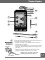


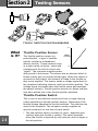


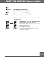
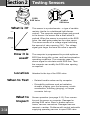


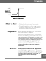


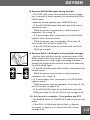

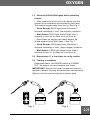

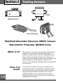

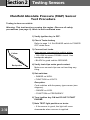
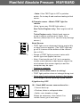

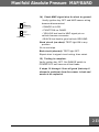
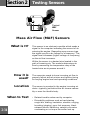
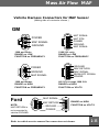
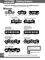
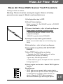
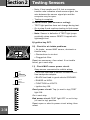
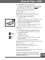

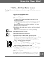

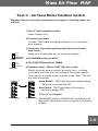
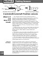


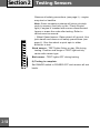
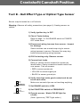
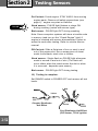

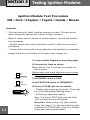


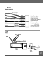


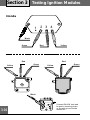
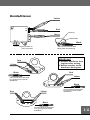
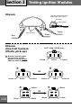

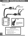

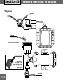
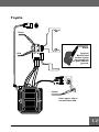
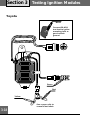
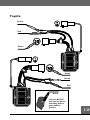
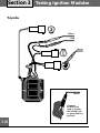
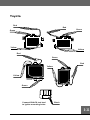


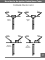


![Trailer Roll Stability (TRS) Installation Manual [L30040]](http://vs1.manualzilla.com/store/data/006020641_1-040a22153212ab13bbec744ca183c148-150x150.png)