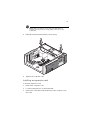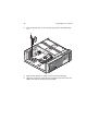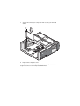
1
Veriton 5600 series
User’s guide
Copyright © 2003 Acer Incorporated
All Rights Reserved.
Veriton 5600 series
User’s guide
Original Issue April 2003
Changes may be made periodically to the information in this publication without obligation
to notify any person of such revision or changes. Such changes will be incorporated in new
editions of this manual or supplementary documents and publications. This company makes
no representations or warranties, either expressed or implied, with respect to the contents
hereof and specifically disclaims the implied warranties of merchantability or fitness for a
particular purpose.
Record the model number, serial number, purchase date, and place of purchase information in
the space provided below. The serial number and model number are recorded on the label
affixed to your computer. All correspondence concerning your unit should include the serial
number, model number, and purchase information.
No part of this publication may be reproduced, stored in a retrieval system, or transmitted, in
any form or by any means, electronic, mechanical, photocopy, recording, or otherwise,
without the prior written permission of Acer Incorporated.
Model Number : _________________________________
Serial Number: ___________________________________
Purchase Date: ___________________________________
Place of Purchase: ________________________________
Acer and the Acer Logo are registered trademarks of Acer Inc. Other company’s product
names or trademarks are used herein for identification purposes only and belong to their
respective companies.
1 First things first
1
System specifications
Package contents
Accessing the user’s guide
5
6
7
2 System tour
Features
Performance
Multimedia
Connectivity
Front panel
Rear panel - VT5600D
Rear panel - VT5600G
Keyboard
Programmable keys
Internet/Suspend keys
Multimedia keys
Volume control/Mute knob
Lock keys
Cursor keys
Windows keys
Function keys
Palm rest
Optical drive
Hard disk
3 Setting up your computer
Arranging a comfortable work area
Adjusting your chair
Positioning your PC
Positioning your monitor
Positioning your keyboard
Positioning your mouse
Connecting peripherals
Connecting your mouse
Connecting your keyboard
Connecting a monitor
Connecting the power cable
Turning on your computer
Turning off your computer
Connecting options
Connecting your printer
Connecting the modem (optional)
9
12
12
12
12
14
16
18
20
21
22
23
24
25
26
27
28
28
29
31
33
36
36
36
37
37
38
39
39
41
43
44
45
46
47
47
48
Contents
iii
iv
Contents
Connecting to the network
Connecting multimedia devices
Connecting USB devices
4 Upgrading your computer
Installation precautions
ESD precautions
Preinstallation instructions
Post-installation instructions
Opening your computer
To remove the computer cover
To replace the computer cover
Internal components
System boards
Mainboard layout
Veriton 5600D mainboard layout
Veriton 5600G mainboard layout
Audio board
Upgrading your computer
Installing additional memory
Replacing the hard disk
Installing an expansion card
5 System utilities
Acrobat Reader
Acer LANScope (optional)
Norton AntiVirus
NTI CD-Maker (for models with CD-RW)
PowerDVD (for models with DVD)
BIOS utility
Reinstalling programs
Recovering your system
Using Backup (Windows XP only)
Disk Defragmenter (Windows XP only)
6 Frequently asked questions
49
50
53
55
58
58
58
59
60
60
61
62
64
64
65
66
69
70
70
72
75
79
83
84
85
87
89
90
91
92
96
97
99
Appendix A: Notices
105
Appendix B: Taking care of your computer
111
Important tips
113
v
Cleaning and servicing
Asking for technical assistance
Index
113
114
115
vi
Contents
1 First things first
This chapter describes the system
specifications and the contents of your
computer package.
4
1 First things first
System specifications
Component
Specification
Processor
•
Intel Pentium®4 1.8 - 3.6 GHz
•
Intel Celeron® 2.0 - 2.6 GHz
System memory
Four SDRAM slots support a maximum of 4 GB dualchannel DDR memory
Chipset
•
Intel MCH 865G
•
Intel MCH 865PE
Graphics
Intel MCH 865G on-die VGA card supporting:
•
DVMT technology
•
Dual View
•
1 optional VGA port on rear
Intel MCH 865PE supporting:
•
Add-on VGA card
Audio
AC97 Codec
LAN
Broadcom 5705 supporting 10/100/1000 MB
connectivity
IDE
40 pin parallel ATA IDE slot
FDD
1.44 MB 3.5 inch floppy drive
PS2
•
PS2 keyboard port
•
PS2 mouse port
USB
Six external USB 2.0 ports
Serial port
One serial port
Printer port
One parallel printer port
Debug
One 4 LED port
Thermal
Dynamic fan speed control
5
Component
Security
Specification
•
Chassis lock (Kensington compatible)
•
Chassis intrusion alarm
Chassis
Three models: H80, H40, H34A
Wake system
Wake on LAN
Wake on modem
Mouse/keyboard
HDD
•
5400 RPM: 40 - 100 GB
•
7200 RPM: 40 GB, 80 GB, 120 GB
Optical Drive
CD-ROM, CD-RW, DVD-ROM, or DVD/CD-RW combo
Operating system
•
Windows 2000
•
Windows XP Home
•
Windows XP Professional
•
Novell
•
SCO Unix
•
Red Hat Linux
•
Mini-Tower 424(H) /200(W) /414(D)
Dimensions
Weight
Thermal
overrides
•
Desktop 135(H) /380(W) /420(D)
•
Small Form Factor 95(H) /324(W) /399(D)
•
Mini-Tower 8.5 kg
•
Desktop 6.5 kg
•
Small Form Factor 5.3 kg
•
System temp >90oC - functions suspended until
system temp is below 90oC
•
CPU temp >110oC - functions suspended until CPU
temp is below 110oC
•
CPU temp >120oC - system auto-shutdown
6
1 First things first
Package contents
Before you unpack your computer, make sure that you have enough
space to set up your computer.
Carefully unpack the carton and remove the contents. If any of the
following items are missing or damaged, contact your dealer
immediately:
•
Veriton 5600 series computer
•
Items contained in the accessory box
•
PS/2 or USB keyboard
•
PS/2 or USB mouse
•
User’s guide and installation poster
•
Other user documentation and third-party software
7
Accessing the user’s guide
This user’s guide is also available on your computer as an Adobe
Acrobat PDF file.
To access the user’s guide (for Windows XP)
1
On the Windows XP taskbar, click on the Start button then select
Help and Support Center.
2
On the Help and Support Center home page, double-click the
Veriton 5600 series Online icon.
To access the user’s guide (for Windows 2000)
1
Double-click on the Veriton 5600 series Online icon on your
Windows desktop.
8
1 First things first
2 System tour
This chapter discusses the features and
components of your computer.
12
2 System tour
Features
Here are just a few of your computer’s many features:
Performance
•
Intel Pentium® 4 supporting FSB up to 800 MHz
or
•
Intel Celeron® CPU supporting FSB up to 400 MHz
•
Intel Hyperthreading Technology supported on 3.06 GHz and
higher Intel Pentium® 4 systems
•
Intel 865G/865PE ICH5 chipset
•
DDR-SDRAM 400/333/266, 4 DIMM slots, Expandable to 4GB dualchannel memory
•
Power management function
•
3.5-inch floppy drive
•
CD-ROM, CD-RW, DVD-ROM, or DVD/CD-RW combo drive
•
High-capacity, Enhanced-IDE hard disk
•
Supports USB 2.0 high-performance peripherals
Multimedia
•
3-D quality audio system via onboard audio controller
•
Audio-in/Line-in, Audio-out/Line-out, Headphone-out, and
Microphone-in interfaces
Note: The system has two microphone-in jacks (front and rear).
However, you can not use both of them at the same time. By
default, your system enables the microphone-in jack in front and
disables the one at the back.
Connectivity
•
Two PS/2 interfaces for mouse and keyboard
•
One serial port
•
One parallel port
13
•
One VGA port
•
Eight Universal Serial Bus (USB) 2.0 ports (two internal, two on the
front and four on the rear panel)
•
High-speed fax/data PCI modem (optional)
•
Broadcom 5705 10/100/1000Base-T Gigabit LAN support with
remote wake-up function
14
2 System tour
Front panel
Your computer’s front panel consists of the following:
Label
Icon
Description
1
Hard disk activity light-emitting diode (LED)
2
System activity indicator
3
Power indicator
4
Power button
5
Optical drive Headphone/Earphone port
6
Floppy drive LED
7
3.5-inch floppy drive
8
Floppy drive eject button
9
Optical drive tray
10
Stop/Eject button
15
Label
Icon
Description
11
Optical drive emergency eject hole
12
Optical drive LED
13
Volume control
14
5.25-inch drive bay
15
Headphone/Earphone port
16
Front microphone-in port (see Note)
17
USB ports
Note: The system has two microphone-in jacks (front and rear).
However, you can not use both of them at the same time. By
default, your system enables the microphone-in jack in front and
disables the one at the back.
16
2 System tour
Rear panel - VT5600D
Your computer’s rear panel consists of the following:
Label
Icon
Color
1
2
Description
Voltage selector switch
Green
3
PS/2 mouse port
System vents
4
Teal or
Turquoise
Serial port
5
Burgundy
Parallel/Printer port
6
Blue
NOT USED
7
White
Network port
8
Keyhole
17
Label
Icon
Color
Description
9
One Touch Recovery button
(Optional)
10
Monitor port
11
S-Video out port
12
Telephone/Handset line port
13
Expansion slots
14
Telephone/Handset line port
15
Light blue
Audio-in/Line-in jack
16
Lime
Audio-out/Line-out jack
17
Pink
Microphone-in jack
18
Black
USB ports
19
Purple
PS/2 keyboard port
20
Power cable socket
21
Power supply
For information on how to connect the peripherals, see “Connecting
peripherals” on page 39 and “Connecting options” on page 47.
18
2 System tour
Rear panel - VT5600G
Your computer’s rear panel consists of the following:
Label
Icon
Color
1
2
Description
Voltage selector switch
Green
3
PS/2 mouse port
System vents
4
Teal or
Turquoise
Serial port
5
Burgundy
Parallel/Printer port
6
Blue
Monitor port
7
White
Network port
8
Keyhole
19
Label
Icon
Color
Description
9
One Touch Recovery button
(Optional)
10
Monitor port
11
S-Video out port
12
Telephone/Handset line port
13
Expansion slots
14
Telephone/Handset line port
15
Light blue
Audio-in/Line-in jack
16
Lime
Audio-out/Line-out jack
17
Pink
Microphone-in jack
18
Black
USB ports
19
Purple
PS/2 keyboard port
20
Power cable socket
21
Power supply
For information on how to connect the peripherals, see “Connecting
peripherals” on page 39 and “Connecting options” on page 47.
20
2 System tour
Keyboard
Your computer comes with a USB keyboard. The keyboard has fullsized keys that include separate cursor keys, two Windows keys, and
twelve function keys.
For information on how to connect your USB keyboard, please see
“Connecting peripherals” on page 39.
No.
Description
1
Programmable keys
2
Internet/Suspend keys
3
Multimedia keys
4
Volume control/Mute knob
5
Scroll lock key
6
Num lock key
7
Cursor keys
8
Application key
21
No.
Description
9
Windows logo key
10
Caps lock
11
Function keys
Programmable keys
The programmable keys help you directly access a URL (Web site) or
launch any program, files, or application in your system. The fifth key is
set to launch the Windows Media Player. If you want to configure the
settings of each key, right click on the Magic Keyboard icon located on
the desktop.
22
2 System tour
Internet/Suspend keys
The Internet/Suspend keys consist of three buttons:
Icon
Key
Description
Email
Launches your email application.
Web
browser
Launches your current default browser.
Suspend
Press this button to put system to sleep.
23
Multimedia keys
Allow you to conveniently play, pause, stop, step forward, or step back
a song or movie using your keyboard.
Icon
Key
Description
Play/Pause
Press to start playing the audio track or
video file. Press again to pause.
Stop
Press to stop playing the audio track or
video file.
Forward
Press to skip forward to the next track or
video file and start playing.
Backward
Press to skip backward to the previous
track or video file and start playing.
24
2 System tour
Volume control/Mute knob
The volume control/mute knob controls the speaker volume.
Turn it clockwise or counterclockwise to adjust the volume.
Press it to toggle between mute and sound.
25
Lock keys
The keyboard has three lock keys which you can toggle on and off to
switch between two functions.
Lock key
Description
Caps Lock
When activated, all alphabetic characters typed
appear in uppercase (same function as pressing
Shift + <letter>).
Num Lock
When activated, the keypad is set to numeric
mode; i.e., the keys function as a calculator
(complete with arithmetic operators such as +, -,
* and /).
Scroll Lock
When activated, the screen moves one line up
or down when you press the up arrow or down
arrow respectively. Take note that Scroll Lock
may not work with some applications.
26
2 System tour
Cursor keys
The cursor keys, also called the arrow keys, let you move the cursor
around the screen. They serve the same function as the arrow keys on
the numeric keypad when the Num Lock is toggled off.
27
Windows keys
The keyboard has two keys that perform Windows-specific functions.
Key
Description
Windows logo key
Start button. Combinations with this key
perform special functions, such as:
Application key
•
Windows + Tab: Activate the next
Taskbar button
•
Windows + E: Explore My Computer
•
Windows + F: Find Document
•
Windows + M: Minimize All
•
Shift + Windows + M: Undo Minimize
All
•
Windows + R: Display the Run dialog box
Opens the applications context menu (same
function as clicking the right button of the
mouse).
28
2 System tour
Function keys
The function keys, F1 - F12, let you perform specific functions,
depending on the application that uses them.
Palm rest
The detachable palm rest provides you a comfortable place to rest your
hands while typing.
29
Optical drive
Your computer may come with a CD-ROM, DVD-ROM or a combo DVD/
CD-RW drive. This drive is located on the front panel of your
computer. The CD-ROM drive allows you to play different types of
compact discs (CDs). The DVD-ROM drive allows you to play not only
old CD-ROMs, CD-I discs, and video CDs, but digital video discs (DVDs)
as well. DVD or DVD-ROM is a type of disc media that holds a
minimum of 4.7-GB (gigabytes), enough for a full-length movie. The
CD-RW drive allows you to record or burn CD-RW (recordable and
rewritable) discs.
CDs and DVDs, like diskettes, are also compact, lightweight, and easy
to carry around. However, they are more delicate than diskettes and
must be handled with extra care.
To insert a CD or DVD into your computer’s CD-ROM or DVD drive:
1
Gently push the Eject button located on the front panel. .
2
When the disc tray slides open, place the CD or DVD gently on the
tray. Make sure that the label or title side of the disc is facing
30
2 System tour
upward. When holding a disc, hold it by the edges to avoid
leaving smudges or fingerprints..
3
Push the Eject button again to close the tray.
To take care of your CDs and DVDs:
•
Keep your discs in a disk case when not in use to avoid scratches or
other damage. Any kind of dirt or damage can affect the data on
the disc, impair the disc lens reader on the CD or DVD drive, or
stop the computer from successfully reading the disc.
•
When handling discs, always hold them by the edges to avoid
smudges or fingerprints.
•
When cleaning discs, use a clean, dust-free cloth and wipe in a
straight line from the center to the edge. Do not wipe in a circular
motion.
•
Clean your CD or DVD drive periodically. You may refer to the
Cleaning kit for instructions. Cleaning kits can be purchased in any
computer or electronics shop.
31
Hard disk
Your computer is preinstalled with a high-capacity Enhanced-IDE
(E-IDE) hard disk.
Refer to “Replacing the hard disk” on page 72 for instructions on how
to upgrade or replace your hard disk.
32
2 System tour
3 Setting up your
computer
This chapter contains step-by-step instructions
on how to set up your computer and connect
additional peripherals.
36
3 Setting up your computer
Arranging a comfortable work area
Working safely begins with the arrangement of your work space and
the proper use of equipment. For this reason, it is very important to
take time and think about how you are going to arrange your work
area. Refer to the diagram on the following page as you set up your
system.
Here are some points to consider:
Adjusting your chair
Having the right kind of chair does not necessarily mean that you’ll be
properly supported. It is necessary to adjust your chair to fit your body.
Proper body posture will make you more comfortable and productive.
•
Avoid tilting your chair. If you have a chair that tilts, lock the tilt
knobs so that your chair will not tilt forward or backward while
you are using your computer.
•
Adjust your chair height in such a way that you can sit on it with
your thighs parallel to the floor and your feet resting flat on the
floor.
•
Rest your body on the chair back. Your torso works harder to
maintain balance if you do not rest your body on the chair back.
Positioning your PC
Take note of the following when selecting a location for your
computer:
•
Do not put your computer near any equipment that might cause
electromagnetic or radio frequency interference such as radio
transmitters, televisions, copy machines, or heating and airconditioning equipment.
•
Avoid dusty areas and extremes of temperature and humidity.
•
You may place your computer beside your desk or under your
table, as long as it does not block the space that you need for
working and moving.
37
Positioning your monitor
Place your monitor at a comfortable viewing distance, usually 50 to 60
centimeters away. Adjust the display in such a way that the top of the
screen is at or slightly below eye level.
Positioning your keyboard
The location of the keyboard is a very important factor to your
posture. Placing it too far away will make your body lean forward
forcing you to sit in an unnatural position. Placing it too high will add
tension to your shoulder muscles.
•
The keyboard should be placed just above your lap. Adjust the
keyboard height by flipping the folding stands located under the
keyboard.
•
Keep your lower arms parallel to the floor as you type. Your upper
arms and shoulders should be relaxed. Then try typing with a light
touch. If you feel any shoulder or neck strain, stop for a while and
check your posture.
38
•
3 Setting up your computer
Position your keyboard in front of your monitor. Putting your
keyboard beside your monitor will make you turn your head while
you type which could add tension to your neck muscles that may
later result in neck strain.
Positioning your mouse
•
The mouse should be placed on the same surface as your keyboard
so that you can reach it with ease.
•
Adjust its position to allow enough space for movement without
making you stretch or lean over.
•
Use your arm to move the mouse. Do not rest your wrist on the
table when moving the mouse.
39
Connecting peripherals
Setting up your computer is easy. For the most part, you only have
four things to connect: the mouse, the keyboard, the monitor, and the
power cable.
Note: The peripherals shown in the connections below are for
your reference only. Actual device models may vary in select
countries.
Connecting your mouse
USB mouse
Plug your USB mouse cable into any of the USB ports
(black port) located on the front and rear panel of your computer.
40
3 Setting up your computer
PS/2 mouse
Plug the PS/2 mouse cable into the PS/2 mouse port
located on the rear panel of your computer.
(green port)
41
Connecting your keyboard
USB keyboard
Plug your USB keyboard cable into any of the USB ports
(black port) located on the front and rear panel of your computer.
42
3 Setting up your computer
PS/2 keyboard
Plug your PS/2 keyboard cable into the PS/2 keyboard port
port) located on the rear panel of your computer.
(purple
43
Connecting a monitor
To connect a monitor, simply plug the CRT monitor cable into the
monitor port
computer.
(blue port) located on the rear panel of your
Note: Refer to the monitor manual for additonal instructions and
information.
44
3 Setting up your computer
Connecting the power cable
Caution! Before you proceed, check the voltage range in your
area. Make sure that it matches your computer’s voltage setting .
If they don’t match, change your computer’s voltage setting
according to your area’s voltage range.
Set the voltage selector switch to the voltage range applicable to your
area (a). Plug the power cable into the power cable socket located on
the rear panel of your computer (b). Then plug the other end of the
power cable into a power outlet.
45
Turning on your computer
After connecting the necessary peripherals and plugging in the power
cable, you are now ready to turn the computer on and get to work.
To turn on your computer:
1.
Turn on all peripherals connected to your computer such as the
monitor, printer, fax, speakers, etc.
2
On the front panel of your computer, press the Power button.
Important: Make sure that the power cable is properly plugged
into an electrical outlet. If you are using a power strip or an AVR
(Auto-Voltage Regulator), make sure that it is plugged in and
turned on.
46
3 Setting up your computer
Turning off your computer
To turn off your computer, follow the steps below.
For Windows XP:
1
On the Windows XP taskbar, click on the Start button, and click
Turn Off Computer, then click Turn Off.
2
Turn off all peripherals connected to your computer.
For Windows 2000:
1
On the Windows 2000 taskbar, click on the Start button, highlight
Shut Down, select Shut down from the drop down window then
click on OK.
2
Turn off all peripherals connected to your computer.
If you cannot shut down your computer normally, press the power
button for at least four seconds. Quickly pressing the button may put
the computer in Suspend mode only.
47
Connecting options
Connecting your printer
Your computer supports parallel, serial and USB printers.
To connect a parallel printer, plug the printer cable into the parallel
port
(burgundy port) located on the rear panel of your computer.
Note: The printer shown below is for your reference only. Actual
device model may vary in select countries.
Note: If you are using a serial printer, connect the printer cable
into either serial port located on the rear panel of your computer.
In the same manner, connect a USB printer by plugging the printer
cable into any of the USB ports located on the front and rear
panel.
48
3 Setting up your computer
Connecting the modem (optional)
Set up your modem connection by plugging the telephone line
and handset line
of your computer.
into their corresponding ports on the rear panel
49
Connecting to the network
You can connect your computer to a Local Area Network (LAN) using a
network cable. To do so, simply plug the network cable into the
network port
computer.
(white port) located on the rear panel of your
Note: Consult your network system administrator or operating
system manual for information on how to configure your network
setup.
50
3 Setting up your computer
Connecting multimedia devices
You can connect multimedia devices such as microphone, earphone or
headphone, external speakers, and audio line-in device. These devices
will allow you to take advantage of your computer’s multimedia
features.
Note: The multimedia devices shown below are for your
reference only. Actual device model may vary in selecrt countries.
Plug the devices in as follows:
Note: For information on how to configure multimedia devices,
consult the documentation that came with each device.
•
microphone: connects to the Microphone-in port
(pink port)
located on the front and rear panel of your computer
Note: The system has two microphone-in jacks (front and rear).
However, you can not use both of them at the same time. By
default, your system enables the microphone-in jack in front and
disables the one at the back.
51
•
earphones, headphones: connect to the Headphone-out port
(lime port) located on the front panel of your computer
Note: To adjust the volume of the headphones, click the Volume
icon located on the taskbar at the bottom of your screen. When
the volume control pops up, drag the Volume control lever to the
desired level. You can also use the Volume control/mute knob on
the keyboard.
52
•
3 Setting up your computer
external speakers: connect to the Audio-out/Line-out jack
(lime jack) located on the rear panel of your computer
•
audio line-in device: connects to the Audio-in/Line-in jack
(light blue jack) located on the rear panel of your computer
53
Connecting USB devices
Universal Serial Bus (USB) is a serial bus design that is capable of
cascading peripherals such as a digital camera, keyboard, mouse,
joystick, scanner, printer and modem. With USB, complex cable
connections can be eliminated.
Your computer comes with six USB ports: two on the front and another
four on the rear panel. These ports support USB 2.0 high-performance
external devices such as webcams and digital still cameras. They also
allow you to connect additional USB devices to your computer without
using up its system resources.
To connect a USB device, simply plug the device cable into any of the
USB ports
(black port).
Note: The USB devices shown below are for your reference only.
Actual device model may vary in select countries.
54
3 Setting up your computer
Note: Some USB devices have a built-in USB port which allows
you to connect or daisy-chain more USB devices.
4 Upgrading your
computer
This chapter contains instructions on how to
upgrade your computer and basic information
about your system boards that you will find
helpful when performing the upgrade process.
58
4 Upgrading your computer
Installation precautions
Before you install any computer component, we recommend that you
read the following sections. These sections contain important ESD
precautions along with preinstallation and post-installation
instructions.
ESD precautions
Electrostatic discharge (ESD) can damage your processor, disk drives,
expansion boards, and other components. Always observe the
following precautions before you install a computer component:
1
Do not remove a component from its protective packaging until
you are ready to install it.
2
Wear a wrist grounding strap and attach it to a metal part of the
computer before handling components. If a wrist strap is not
available, maintain contact with the computer throughout any
procedure requiring ESD protection.
Preinstallation instructions
Always observe the following before you install any component:
1
Turn off your computer and all the peripherals connected to it
before opening it. Then unplug all cables from the power outlets.
2
Open your computer according to the instructions on page 60.
3
Follow the ESD precautions described above when handling a
computer component.
4
Remove any expansion board(s) or peripheral(s) that block access
to the DIMM sockets or other component connector.
5
See the following sections for specific instructions on the
component you wish to install.
Warning! Failure to turn off the computer properly before
you start installing components may cause serious
damage.
Do not attempt to open, upgrade and reconfigure your
computer unless you are a qualified service technician.
59
Post-installation instructions
Observe the following after installing a computer component:
1
See to it that all components are installed according to the stepby-step instructions in their respective sections.
2
Replace any expansion board(s) or peripheral(s) that you removed
earlier.
3
Replace the computer cover.
4
Connect the necessary cables and turn on your computer.
60
4 Upgrading your computer
Opening your computer
Caution! Before you proceed, make sure that you have turned
off your computer and all peripherals connected to it. Read the
“Preinstallation instructions” on page 58.
You need to open your computer before you can install additional
components. See the following section for instructions.
To remove the computer cover
1
Turn off your computer and unplug all cables.
2
Place your computer on a flat, steady surface.
3
Turn the thumbscrews counterclockwise with your fingers to
release the cover (1,2).
Hold the cover with both hands.
Slide it back about an inch (3) and then gently lift it upward to
detach it (4).
61
To replace the computer cover
1
Align the cover to the housing frame (1) and then push it in to
slide it back into place (2).
Secure the cover with the thumbscrews you removed earlier (3,4).
62
4 Upgrading your computer
Internal components
The figure below shows what your computer looks like once you
remove the cover:
No.
Component
1
Expansion slots
2
Mainboard
3
Metal brackets (hard disk drive frame)
4
Power supply
63
No.
Component
5
Hard disk frame
6
CD-ROM/DVD-ROM/CD-RW drive frame
Note: The mainboard model shown in the figure above may not
be exactly the same with the one found in your computer.
64
4 Upgrading your computer
System boards
Mainboard layout
The mainboard becomes accessible once you open your computer.
Refer to the section below for the corresponding mainboard layout of
your Veriton 5600 series computer model.
65
Veriton 5600D mainboard layout
66
4 Upgrading your computer
Veriton 5600G mainboard layout
67
Label
Component
AGP1
AGP slot (VT5600G only) see note
AUD1
Line-in (top), line-out (middle), and rear microphonein (bottom) ports
ATX1
Power connector
BIOS1
BIOS chipset
BT1
Battery
CD1
CD-in connector
COM1
Serial connector
DLED1
D-Bracket (LANScope) connector
DIMM1
DIMM sockets 1-4
DIMM2
DIMM3
DIMM4
FN1
3-pin CPU fan connector
FN6
CPU ZIF socket
FAN2
3-pin system fan connector
FDD1
FDD connector
IDE1
IDE 1 connector
IDE2
IDE 2 connector
JAUD1
Audio FPIO connector
JBAT1
1-2 Normal
2-3 Clear CMOS
JCI1
Intrusion connector
68
4 Upgrading your computer
Label
Component
JFP1
HDD LED, Power LED connector
Power button and Reset switch controller
JKBMS1
PS/2 mouse (upper) and keyboard (lower) ports
JPW1
Power connector (12V power)
JRECOVER
One Touch Recovery button connector
LPT1
Parallel/Printer port
PCI1 to PCI3
PCI slots 1 to 3
SATA1
SATA2
Serial HDD connectors
SER1
Serial port
U10
Northbridge
U19
Southbridge
USB1
USB ports
USB2
Front USB 2.0 connector or Unused
USB3
Front USB 2.0 connector or Unused
USB4
USB ports
VGA1
Monitor port (VT5600G only)
Note: For the location of the AGP slot on the Veriton 5600G
mainboard, see page 66.
69
Audio board
The audio board that came with your computer should look like the
figure that follows.
Label
Description
CN1
USB 1.1 connector
CN2 and
CN3
USB ports
CN4
Standard Audio connector - connects to the CN16 of the
mainboard
CN5
USB connector - connects to the CN18 connector of the
mainboard
JK1
Microphone-in jack (front) see note
JK2
Audio-out port
JP1
Audio connector
Note: The system has two microphone-in jacks (front and rear).
However, you can not use both of them at the same time. By
default, your system enables the microphone-in jack in front and
disables the one at the back.
70
4 Upgrading your computer
Upgrading your computer
Certain components of your computer are upgradeable such as the
memory, the hard disk, the CPU and the expansion cards. You need to
observe the “Installation precautions” on page 58 when installing or
removing a computer component. However, for safety purposes, we
do not recommend that you perform these upgrades yourself. If you
want to replace or upgrade any of these components, contact your
dealer or a qualified service technician for assistance.
Note: The mainboard model shown in the following figures may
not be exactly the same with the one found in your computer.
Installing additional memory
The four 184-pin sockets on the mainboard support Double Data Rate
(DDR) Synchronous Dynamic Random Access Memory (SDRAM)-type
DIMMs. You may install 128-MB, 256-MB, 512-MB or 1-GB DIMMs for a
maximum memory capacity of 4 GB.
The DDR DIMMs should work under 2.5 volts. You can install PC2100/
DDR266, PC2700/DDR333, or PC3200/DDR400 modules in the DDR
DIMM sockets. Contact your dealer for qualified DIMM vendors.
Each DDR DIMM socket is independent from the other. This
independence allows you to install DDR DIMMs with different
capacities to form different configurations.
To remove a DDR DIMM
Note: The DDR DIMM has only one notch located on the center
of the module.
1.
Remove the computer cover (see page 60).
2.
Locate the DDR DIMM socket on the mainboard.
71
3.
Press the holding clips on both sides of the DDR DIMM socket
outward to release the DDR DIMM (1,2). Gently pull the DDR
DIMM out of the socket (3).
To install a DDR DIMM
1.
Locate the DDR DIMM socket on the mainboard.
72
2
4 Upgrading your computer
Align the DDR DIMM with the socket (1). Press the DDR DIMM into
the socket until the clips lock onto the DDR DIMM (2,3).
Note: The DDR DIMM sockets are slotted to ensure proper
installation. If you insert a DDR DIMM but it does not fit easily into
the socket, you may have inserted it incorrectly. Turn the DDR
DIMM around and try to insert it again.
To reconfigure your computer
Your computer automatically detects the amount of additional
memory installed. Run the BIOS Setup utility to view the new value for
total system memory and make a note of it.
Replacing the hard disk
Follow these steps to replace your computer’s hard disk:
1
Remove the computer cover.
73
2
Remove the screw that secures the metal bracket frame to the
housing. Set the screw aside.
3
Lift up the metal bracket and pull it out (1,2).
4
Detach all cables connected to the hard disk.
74
4 Upgrading your computer
5
Remove the four screws that hold the hard disk to the disk frame
and detach the hard disk. Set the screws aside.
6
Insert the new hard disk into the frame and secure it with four
screws.
7
Reattach all cables to the new hard disk.
75
Note: Make sure that the other ends of the disk cables are
securely connected to their corresponding connectors on the
mainboard.
8
Reinstall the metal bracket frame to the housing.
9
Replace the computer cover.
Installing an expansion card
To install an expansion card:
1
Remove the computer cover.
2
Locate an empty PCI slot on the mainboard.
3
Remove the screw that holds the bracket to the computer. Save
the screw.
76
4 Upgrading your computer
4
Pull out the bracket on the housing opposite the selected empty
slot.
5
Remove the expansion card from its protective packaging.
6
Align the card in the empty bracket and then insert it into the slot.
Make sure that the card is properly seated.
77
7
Secure the card to your computer with a screw you removed
earlier.
8
Replace the computer cover.
When you turn on the computer, BIOS automatically detects and
assigns resources to the newly-installed devices.
78
4 Upgrading your computer
5 System utilities
This chapter describes the applications that
came with your computer.
82
5 System utilities
Depending on the hardware and optional features installed in your
computer, your system came bundled with several program utilities
designed to streamline your computer’s operations. These utilities may
include any of the following:
•
Acrobat® Reader™
•
Acer LANScope Client Manager (optional)
•
Norton AntiVirus
•
NTI CD-Maker
•
PowerDVD
•
BIOS utility
•
Acer One-Touch Recovery (System restore utility)
If your computer is configured with Microsoft Windows XP the
following utilities can be used to monitor and maintain system health.
•
Backup
•
Disk Defragmenter
All of the applications that came with your computer are very easy to
use. However, if you need more help and information, you may refer
to the online help documentation provided in each software
application.
83
Acrobat Reader
Acrobat Reader is a software that lets you view, navigate, browse and
print Adobe Portable Document Format (PDF) files on all major
computer platforms.
To read a PDF document
•
you can:
Simply double click on any file with an icon like that shown above.
or
1
On the windows taskbar, click on the Start button, highlight
Programs, and select Acrobat Reader.
2
Once the program is running, select Open from the File menu.
3
Select the file you wish to view in the Open file browser and click
the Open button.
For more information about Acrobat Reader, you may refer to the
Acrobat Reader Help menu.
84
5 System utilities
Acer LANScope (optional)
Acer LANScope allows desktop management via the Web, standard
network, or dial-up connections. It is compatible with the leading
management specifications, such as Wired for Management 2.0,
Desktop Management Interface (DMI) v2.0, and others.
Your computer may be bundled with a LANScope installation CD. To
install LANScope:
1
Insert the LANScope installation CD into the optical drive.
Caution! Make sure that the LANScope installation CD is
properly inserted into the optical drive. Improper insertion may
damage both the CD and the drive.
Refer to page 25 for instructions on how to insert a CD into your
computer's optical drive.
2
Follow all onscreen instructions until installation is completed.
For more information on how to use the LANScope, you may refer to
the LANScope Help menu.
Note: Acer LANScope currently supports Windows 98, Windows
Me, Windows 2000 and Windows XP platforms.
85
Norton AntiVirus
Norton AntiVirus is an anti-virus software which finds and repairs
infected files, protects against viruses to keep your computer data safe
and secure. It also scans incoming email attachments for viruses. It
provides useful virus detection and repair facilities.
How do I check for viruses using Norton AntiVirus?
A full system scan scans all files on your computer. To perform a system
scan:
1
Start Norton AntiVirus
•
Double click on the Norton AntiVirus Icon on the desktop
or
•
Click on the Start menu in the Windows taskbar, highlight
Programs, and select Norton AntiVirus.
2
In the Norton AntiVirus main window, click Scan for Viruses.
3
In the Scan for Viruses pane, click Scan My Computer.
4
Under Actions, click Scan.
When the scan is complete, a scan summary appears.
5
When you are done reviewing the summary, click Finished.
86
5 System utilities
You can schedule customized virus scans that run unattended on
specific dates and times or at periodic intervals. If you are using the
computer when the scheduled scan begins, it runs in the background
so that you do not have to stop working.
For more information about Norton AntiVirus, including setting up
custom scans and scheduling scans, refer to the Norton AntiVirus Help
menu.
87
NTI CD-Maker
(for models with CD-RW)
The NTI CD-Maker is a CD-Recording software which allows you to
create and copy audio, data and videos to CD-R or CD-RW discs.
To copy an audio or data disc:
1
Click the Quick Burning icon
on the desktop.
2
Insert the CD you would like to copy into the source drive and a
blank disc into the target drive.
3
Choose the source and target drives from the pull-down lists.
88
4
5 System utilities
Click the Start button to begin copying.
For more information about NTI CD-Maker and its other features, refer
to the NTl CD-Maker Help menu.
89
PowerDVD (for models with DVD)
PowerDVD is a high-quality, pure software DVD player which brings
high-quality movies and karaoke to your multimedia PC. You can play
back high resolution DVD titles or MPEG-2 files with MPEG-2 video and
Dolby Digital (AC-3) audio. PowerDVD provides a complete set of
commands for navigation and advanced features such as multi-angle
switching, multi-language and multi-subtitle selection, and parental
control. It also has the i-Power Internet Enabling feature, which links
to online DVD resources via the Power DVD Desktop Portal Page.
How do I open PowerDVD and watch a DVD?
In most cases, when you insert a DVD into your computer’s optical
drive, PowerDVD will automatically open a viewer window and the
control panel and begin playing.
If PowerDVD does not open automatically:
1
Click the Start button in the taskbar.
2
Highlight All Programs
3
Click the Cyberlink PowerDVD tab
4
Select PowerDVD
When PowerDVD opens simply press the play button
playback.
to begin
For more information about Cyberlink PowerDVD and its other
features, refer to the PowerDVD Help menu.
90
5 System utilities
BIOS utility
The BIOS utility is a hardware configuration program built into your
computer's Basic Input/Output System (BIOS). Since most computers
are already properly configured and optimized, there is no need to run
this utility. However, if you encounter configuration problems and get
the "Run Setup" message, you will need to run this utility.
Note: Before you run BIOS, make sure that you have saved all
open files. The computer reboots immediately after you exit
Setup.
To run the BIOS utility, press the Del key on your keyboard during
computer boot up.
91
Reinstalling programs
If you uninstall one of the preinstalled programs and want to reinstall
it, do the following:
1.
Make sure that the system is turned on.
2.
Insert the System CD into the CD or DVD drive.
3.
Select the application that you want to reinstall.
4.
Follow all onscreen instructions until you finish the installation.
92
5 System utilities
Recovering your system
If your operating system files are lost or damaged, the recovery process
will restore your system's original factory default settings. Your Acer
Veriton series computer includes a One Touch Recovery button, a
feature that makes restoring your system quick and easy.
One Touch Recovery works from a hidden 2 GB partition on your hard
drive that contains all the information required to restore your system.
There are two ways to initate recovery. If your computer is not
equipped with the (optional) One Touch Recover button, you can press
Alt + F10 after the BIOS finishes running the Power On Self Test (POST).
Warning: Initiating the recovery operation while the
operating system is running will result in abnormal
shutdown and may make your current OS unstable or
unusable.
After the POST runs, you have only 1.5 seconds to press Alt + F10.
Follow all onscreen instructions.
You can also follow the steps below:
1
Locate the (optional) One touch recovery button. See the image
on page 16 or page 18.
93
2
Press the button. After a moment the following screen will appear
on your display.
3
Click OK. You will be prompted again to continue.
94
5 System utilities
4
Click OK again.
5
After 15 seconds the system will reboot and initate the restore
operation.
6
After the recovery operation finishes the system will reboot again.
You will be required to go through the setup process again.
95
Caution! Running the Recovery operation will erase all files
previously saved in your computer so make sure to back up your
important files before starting the recovery process.
If you attempt to restore your system using the One Touch feature, and
the system DOES NOT respond, contact your local vendor or authorised
Acer representative immediately.
96
5 System utilities
Using Backup (Windows XP only)
The Backup utility creates copies of information on your hard disk. In
the event that the original data on your hard disk is erased or
overwritten, or becomes inaccessible because of a hark disk
malfunction, you can use the copy to restore your lost or damaged
data.
How do I back up files from my hard drive?
To run the Backup utility:
1
Click the Start button in the taskbar.
2
Highlight All Programs
3
Click Accessories
4
Select System Tools
5
Click Backup
When Backup starts, follow the onscreen instructions to set up your
backup profile and schedule.
For more information about Backup, refer to Windows XP help.
97
Disk Defragmenter (Windows XP only)
The disk degfragmentation utility consolidates files and folders on
your computer’s hard disk. This allows your computer to access files
and folders and save new data more efficiently. By consolidating your
files and folders, the defragmenter also consolidates the volume’s free
space, making it less likely that new files will be fragmented.
How do I defragment my hard drive?
To run the Disk Defragmenter:
1
Click the Start button in the taskbar.
2
Highlight All Programs
3
Click Accessories
4
Select System Tools
5
Click Disk Defragmenter
When Disk Defragmenter opens, select a drive/volume and click
Analyze. The system will quickly examine the volume and determine
wether it needs to be defragmented or not.
For more information about Disk Defragmenter, refer to Windows XP
help.
98
5 System utilities
6 Frequently asked
questions
This chapter instructs you on how to deal with
common system problems. Read it before
calling a technician if a problem occurs.
Solutions to more serious problems require
opening up the computer. Do not attempt to
open the computer by yourself. Contact your
dealer or an authorized service center for
assistance.
0 0 0 0 0 0 0 0 0 0 0 0 0 0 0 0 0 0 0 0 0 0 0 0 0 0 0 0 0 0 0 0 0 0 0 0 0 0 0 0 0 0 0 0 0 0 0 0 0 0 0 0 0 0 0 0 0 0 0 0 0 0 0 0 0 0 0 0 0 0 0 0 0 0 0 0 0 0 0 0 0 0 0 0 0 0 0 0 0 0 0 0 0 0 0 0 0 0 0 0 0 0 0 0 0 0 0 0 0 0 0 0 0 0 0 0 0 0 0 0 0 0 0 0 0 0 0 0 0 0 0.
key link: 0www.acersupport.com
102
6 Frequently asked questions
FAQs
The following questions are possible situations that may arise during
the use of your computer and each is followed by easy answers and
solutions to the situation.
Q: I pressed the power switch but the system did not boot up.
A: Check the LED located above the power switch.
If the LED is not lit, no power is being applied to the system. Do any of
the following:
•
Check if the voltage selector switch located on the rear panel of
the computer is set to the correct voltage.
•
Check if you plugged the power cable properly into an electrical
outlet.
•
If you are using a power strip or AVR, make sure that it is plugged
in and turned on.
If the LED is lit, check the following:
•
Is a nonbootable (nonsystem) diskette in the floppy drive? If yes,
remove or replace it with a system diskette and press Ctrl + Alt +
Del to restart your computer.
•
The operating system files may be damaged or missing. Insert the
startup disk you created during Windows setup into the floppy
drive and press Ctrl + Alt + Del to restart your computer. This will
automatically diagnose your system and make necessary fixes.
However, if the diagnostic utility still reports a problem, then you
may have to perform the recovery process to restore your system
to its original default factory settings.
Note: For more information about recovering your system, refer
to page 86.
103
Q: Nothing appears on the screen.
A: Your computer’s power management function automatically blanks
the screen to save power. Just press any key to turn the display back
on.
If pressing a key does not work, you can restart your computer. If
restarting your computer does not work, contact your dealer or the
technical support center for assistance.
Q: The printer does not work.
A: Do the following:
•
Make sure that the printer is connected to a power outlet and that
it is turned on.
•
Make sure that the printer cable is connected securely to the
system’s parallel port and the corresponding port on the printer.
See “Connecting your printer” on page 43 for information on how
to connect the printer to your computer.
•
For additional information concerning the printer, refer to the
printer’s documentation.
Q: No sound comes out from the computer.
A: Check the following:
•
The volume may be muted. Look for the Volume icon on the
taskbar. If it is crossed-out, click on the icon and deselect the
Mute option. You can also press the volume control/mute knob
on your USB keyboard to toggle from mute to sound on.
•
If headphones, earphones, or external speakers are connected to
the line-out jack of your computer, the internal or built-in speakers
are automatically turned off.
104
6 Frequently asked questions
Q: System cannot read diskette, hard disk, CD or DVD information.
A: Check the following:
•
Make sure that you are using the correct type of disc. See page 25.
•
Make sure the CD or DVD is inserted into the drive correctly.
•
Check if the CD or DVD is clean and not scratched.
•
Check your drive by using a good (i.e., undamaged) disc. If your
drive can not read the information on the good disc there may be
a problem with the drive. Contact your dealer or technical support
center for assistance.
Q: System cannot write data on the hard disk or CD-R/CD-RW.
A: Check the following:
•
Make sure the diskette or hard disk is not write-protected. Refer to
the Optical drive section on page 25.
•
Make sure that you are using the correct type of disc or diskette.
Refer to the Optical drive section on page 25.
105
Appendix A:
Notices
107
FCC notice
This device has been tested and found to comply with the limits for a Class B
digital device pursuant to Part 15 of the FCC Rules. These limits are designed to
provide reasonable protection against harmful interference in a residential
installation. This device generates, uses, and can radiate radio frequency
energy and, if not installed and used in accordance with the instructions, may
cause harmful interference to radio communications.
However, there is no guarantee that interference will not occur in a particular
installation. If this device does cause harmful interference to radio or television
reception, which can be determined by turning the device off and on, the user
is encouraged to try to correct the interference by one or more of the following
measures:
•
Reorient or relocate the receiving antenna
•
Increase the separation between the device and receiver
•
Connect the device into an outlet on a circuit different from that
to which the receiver is connected
•
Consult the dealer or an experienced radio/television technician
for help
Notice: Shielded cables
All connections to other computing devices must be made using shielded cables
to maintain compliance with FCC regulations.
Notice: Peripheral devices
Only peripherals (input/output devices, terminals, printers, etc.) certified to
comply with the Class B limits may be attached to this equipment. Operation
with noncertified peripherals is likely to result in interference to radio and TV
reception.
Caution! Changes or modifications not expressly approved by
the manufacturer could void the user’s authority, which is granted
by the Federal Communications Commission, to operate this
computer.
108
Appendix A: Notices
Use conditions
This part complies with Part 15 of the FCC Rules. Operation is subject to the
following two conditions: (1) this device may not cause harmful interference,
and (2) this device must accept any interference received, including interference
that may cause undesired operation.
Notice: Canadian users
This Class B digital apparatus meets all requirements of the Canadian
Interference-Causing Equipment Regulations.
Remarque à l’intention des utilisateurs canadiens
Cet appareil numérique de la classe B respected toutes les exigences du
Règlement sur le matériel brouilleur du Canada.
Important safety instructions
Read these instructions carefully. Save these instructions for future reference.
1.
Follow all warnings and instructions marked on the product.
2.
Unplug this product from the wall outlet before cleaning. Do not
use liquid cleaners or aerosol cleaners. Use a damp cloth for
cleaning.
3.
Do not use this product near water.
4.
Do not place this product on an unstable cart, stand, or table. The
product may fall, causing serious damage to the product.
5.
Slots and openings in the housing and the back or bottom are
provided for ventilation; to ensure reliable operation of the
product and to protect it from overheating, these openings must
not be blocked or covered. The openings should never be blocked
by placing the product on a bed, sofa, rug, or other similar surface.
This product should never be placed near or over a radiator or
heat register, or in a built-in installation unless proper ventilation
is provided.
6.
This product should be operated from the type of power indicated
on the marking label. If you are not sure of the type of power
available, consult your dealer or local power company.
7.
Do not allow anything to rest on the power cord. Do not locate
this product where persons will walk on the cord.
8.
If an extension cord is used with this product, make sure that the
total ampere rating of the equipment plugged into the extension
cord does not exceed the extension cord ampere rating. Also,
109
make sure that the total rating of all products plugged into the
wall outlet does not exceed the fuse rating.
9.
Never push objects of any kind into this product through cabinet
slots as they may touch dangerous voltage points or short out
parts that could result in a fire or electric shock. Never spill liquid
of any kind on the product.
10. Do not attempt to service this product yourself, as opening or
removing covers may expose you to dangerous voltage points or
other risks. Refer all servicing to qualified service personnel.
11. Unplug this product from the wall outlet and refer servicing to
qualified service personnel under the following conditions:
a
When the power cord or plug is damaged or frayed
b
If liquid has been spilled into the product
c
If the product has been exposed to rain or water
d
If the product does not operate normally when the operating
instructions are followed. Adjust only those controls that are
covered by the operating instructions since improper
adjustment of other controls may result in damage and will
often require extensive work by a qualified technician to
restore the product to normal condition.
e
If the product has been dropped or the cabinet has been
damaged
f
If the product exhibits a distinct change in performance,
indicating a need for service.
12. Replace the battery with the same type as the product's battery we
recommend. Use of another battery may present a risk of fire or
explosion. Refer battery replacement to a qualified serviceman.
13. Warning! Batteries may explode if not handled properly. Do not
disassemble or dispose of them in fire. Keep them away from
children and dispose of used batteries promptly.
14. Use only the proper type of power supply cord set (provided in
your accessories box) for this unit. It should be a detachable type:
UL listed/CSA certified, type SVT, rated 7A 125V minimum, VDE
approved or its equivalent. Maximum length is 15 feet (4.6
meters).
110
Appendix A: Notices
Laser compliance statement
The CD or DVD drive in this computer is a laser product. The CD or DVD drive’s
classification label (shown below) is located on the drive.
CLASS 1 LASER PRODUCT
CAUTION: INVISIBLE LASER RADIATION WHEN OPEN. AVOID EXPOSURE TO
BEAM.
Lithium battery statement
CAUTION
Danger of explosion if battery is incorrectly replaced. Replace only with the
same or equivalent type recommended by the manufacturer. Discard used
batteries according to the manufacturer’s instructions.
Macrovision® statement
This product incorporates copyright protection technology that is protected by
method claims of certain U.S. patents and other intellectual property rights
owned by Macrovision Corporation and other rights owners. Use of this
copyright protection technology must be authorized by Macrovision
Corporation, and is intended for home and other limited viewing uses only
unless otherwise authorized by Macrovision Corporation. Reverse engineering
or disassembly is prohibited.
Year 2000 compliance statement
Your computer carries the "Hardware NSTL Tested Year 2000 Compliant" logo,
which certifies that this model has been tested by NSTL using the YMark2000
test, and has been found to meet NSTL's standards for Year 2000 hardware
compliance.
111
Appendix B:
Taking care
of your
computer
113
Please read the important instructions listed in this section. Following
these instructions will help you maximize the durability of your
computer.
Important tips
•
Do not expose the computer to direct sunlight. Do not place it
near sources of heat, such as a radiator.
•
Do not expose the computer to temperatures below 0oC (32oF), or
above 50oC (122oF).
•
Do not subject the computer to magnetic fields.
•
Do not expose the computer to rain or moisture.
•
Do not spill water on the computer.
•
Do not subject the computer to heavy shock or vibration.
•
Do not expose the computer to dust and dirt.
•
Never place the system on uneven surfaces.
•
Do not step on the power cord or place heavy objects on top of it.
Carefully route the power cord and any cables away from personal
traffic.
•
When unplugging the power cord, do not pull on the cord itself
but pull on the plug.
•
The total ampere rating of the equipment plugged in should not
exceed the ampere rating of the cord if you are using an extension
cord. Also, the total current rating of all equipment plugged into
a single wall outlet should not exceed the fuse rating.
•
Check the documentation that came with your software programs
to see if you can select other combinations of resolution and color.
These adjustments could make viewing the screen more
comfortable.
Cleaning and servicing
To clean your computer and keyboard
1
Turn off the computer and unplug the power cord.
114
2
Appendix B: Taking care of your computer
Use a soft cloth moistened with water and gently wipe the exterior
of the computer and the keyboard. Do not use liquid or aerosol
cleaners.
To clean your pointing device
To clean a regular mouse (with rubber ball)
1
Open the circular cover underneath the mouse.
2
Take out the rubber ball and wipe it with a soft, damp cloth.
3
Put the ball back and close the cover.
To clean an optical mouse
For users of an optical mouse, refer to the documentation that came
with your mouse for maintenance instructions.
To clean your monitor
Make sure that you keep your screen clean. For cleaning instructions,
refer to the documentation that came with your monitor.
When to contact a service technician
•
If you dropped and damaged the computer
•
If liquid has been spilled into the computer
•
If the computer is not operating normally
•
If a computer problem persists even after you have checked and
done the troubleshooting tips discussed in the “Frequently-asked
questions” section on page 99
•
If your problem is not listed in the “Frequently-asked questions”
section on page 99
•
If you want to replace or upgrade any of your computer’s internal
components
Asking for technical assistance
For technical assistance, contact your local dealer or distributor. You
may also access the Web site (www.acersupport.com) for information
on how and where to contact the service centers available in your area.
115
Index
I
A
accessing the user’s guide
applications 82
7
B
BIOS utility
90
C
computer cover
remove 60
replace 61
computer maintenance 113
cleaning 113
servicing 113
connecting options
multimedia devices 50
audio line-in device 52
earphones/headphones 51
external speakers 50
joystick 50
microphone 50
network 47, 49
printer 47
D
disk drives
CD-ROM/DVD-ROM/CD-RW drive
inserting CDs/DVDs 29
taking care CDs/DVDs 30
hard disk drive 31
F
features 12
connectivity 12
multimedia 12
performance 12
Frequently-asked questions 102
blank screen 103
no audio 103
no sound 103
printer not working 103
system cannot read disk 104
system cannot write to disk 104
system did not boot up 102
front panel 14
internal components 62
internet/suspend key
email 22
suspend 22
web browser 22
K
keyboard 20
application key 27
caps lock 21
cursor keys 20
function keys 21
internet/suspend keys 20
multimedia keys 20
num lock key 20
programmable keys 20
scroll lock key 20
volume control/mute knob
Windows logo key 21
L
lock keys
caps lock 25
num lock 25
scroll lock 25
M
multimedia key
forward 23
play/pause 23
stop 23
N
NTI
87
P
PowerDVD
89
R
rear panel 16, 18
recovering your system
92
S
safety instructions 108
setting up computer 36, 39
area 36
chair 36
connecting peripherals
external monitor 43
20
116
Index
power cable 44
USB mouse 39
keyboard 37
monitor 37
mouse 38
software 82
Norton AntiVirus 85
NTI CD-Maker 87
system boards 64
audio board 69
mainboard 64
system utilities
Acrobat Reader 83
Norton AntiVirus 85
NTI CD-Maker 87
PowerDVD 89
reinstalling programs 91
T
turning off computer
46
software shutdown 46
suspend mode 46
turning on computer 45
45
U
upgrade
add memory 70
install DDR DIMM 71
reconfigure computer 72
computer 64, 70
install an expansion card 75
installation precautions
post-installation 59
replace components 64
memory 70
USB devices 53
user’s guide 7