1
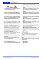
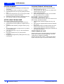
www.nilfisk-alto.com FLOORTEC R 360 P DEUTSCH BETRIEBSANLEITUNG FRANÇAIS MANUEL D’UTILISATION ENGLISH NEDERLANDS USER MANUAL GEBRUIKSAANWIJZING B D 1 8 E 9 10 11 2 6 S310027 7 5 3 9 F 4 S310028 G S310204 C 29 10 S310029 35 39 1 34 H S310030 I 38 15 36 6 7 8 11 24 16 13 32 37 3 2 4 33 1 31 9 5 23 18 S310198 12 14 6 7b J 27 21 2 1 S310032 K 22 7a 20 26 11 17 25 19 S310205 S310199 S310034 USER MANUAL ENGLISH INTRODUCTION ................................................................................................................................... 2 MANUAL PURPOSE AND CONTENTS ........................................................................................................... 2 TARGET ........................................................................................................................................................... 2 HOW TO KEEP THIS MANUAL ....................................................................................................................... 2 IDENTIFICATION DATA ................................................................................................................................... 2 OTHER REFERENCE MANUALS .................................................................................................................... 2 SPARE PARTS AND MAINTENANCE ............................................................................................................. 2 CHANGES AND IMPROVEMENTS ................................................................................................................. 2 SAFETY ................................................................................................................................................. 3 SYMBOLS ......................................................................................................................................................... 3 GENERAL INSTRUCTIONS ............................................................................................................................. 3 UNPACKING ......................................................................................................................................... 4 MACHINE DESCRIPTION ..................................................................................................................... 5 OPERATION CAPABILITIES ............................................................................................................................ 5 CONVENTIONS ................................................................................................................................................ 5 CONTROL PANEL DESCRIPTION .................................................................................................................. 5 OUTSIDE VIEW ................................................................................................................................................ 5 UNDER HOOD ................................................................................................................................................. 6 TECHNICAL DATA ........................................................................................................................................... 6 ELECTRICAL FUSES ....................................................................................................................................... 7 ACCESSORIES/OPTIONS ............................................................................................................................... 7 USE ........................................................................................................................................................ 8 BEFORE MACHINE START-UP ....................................................................................................................... 8 MACHINE START AND STOP ......................................................................................................................... 8 MACHINE OPERATION ................................................................................................................................... 9 HOPPER DUMPING ....................................................................................................................................... 10 AFTER USING THE MACHINE ...................................................................................................................... 10 PUSHING/TOWING THE MACHINE .............................................................................................................. 10 MACHINE LONG INACTIVITY ....................................................................................................................... 10 FIRST PERIOD OF USE ................................................................................................................................ 10 MAINTENANCE .................................................................................................................................. 11 SCHEDULED MAINTENANCE TABLE .......................................................................................................... 11 MAIN BROOM HEIGHT CHECK AND ADJUSTMENT .................................................................................. 12 MAIN BROOM REPLACEMENT .................................................................................................................... 12 SIDE BROOM HEIGHT CHECK AND ADJUSTMENT ................................................................................... 13 SIDE BROOM REPLACEMENT ..................................................................................................................... 13 DUST FILTER CLEANING AND INTEGRITY CHECK ................................................................................... 13 SKIRT HEIGHT AND OPERATION CHECK .................................................................................................. 14 HOOD SAFETY SWITCH OPERATION CHECK ........................................................................................... 14 SAFETY FUNCTIONS ......................................................................................................................... 15 EMERGENCY SWITCH .................................................................................................................................. 15 HOOD SAFETY SWITCH ............................................................................................................................... 15 DRIVER'S SEAT MICROSWITCH .................................................................................................................. 15 TROUBLESHOOTING ........................................................................................................................ 15 SCRAPPING ........................................................................................................................................ 15 EC CERTIFICATE OF CONFORMITY ................................................................................................ 16 146 2598 000(1)2005-03 A FLOORTEC R 360 P 1 ENGLISH USER MANUAL INTRODUCTION MANUAL PURPOSE AND CONTENTS The purpose of this Manual is to provide the operator with all necessary information to use the machine properly in a safe and autonomous way. It contains information about technical characteristics, operation, machine storage, maintenance, spare parts and safety conditions. Before carrying out any procedure on the machine, the operators and technicians in charge of the machine maintenance must read this manual carefully. Contact an authorised Nilfisk-Alto Service Center in case of doubts regarding the interpretation of the instructions and for any further information. OTHER REFERENCE MANUALS Petrol Engine Use and Maintenance Manual, supplied with the machine, which is to be considered an integral part of this manual. Moreover, the following manuals are available: – Spare parts list (supplied with the machine). – Service manual (that can be consulted at Nilfisk-Alto Service Centers). SPARE PARTS AND MAINTENANCE This manual is intended for qualified operators and technicians involved in the machine maintenance. All necessary operating, maintenance and repair procedures must be carried out by qualified personnel or by Nilfisk-Alto Service Centers (listed at the end of this manual). Only original spare parts and accessories must be used. Call Nilfisk-Alto for service or to order spare parts and accessories, specifying the machine model and serial number. HOW TO KEEP THIS MANUAL CHANGES AND IMPROVEMENTS The User manual must be kept near the machine, inside an adequate case, far from liquids and other substances that can cause damage to it. Nilfisk-Alto constantly improves its products and reserves the right to make changes and improvements at its discretion without being obliged to apply such benefits to the machine that were sold previously. Any change and/or addition of accessory must be approved and performed by Nilfisk-Alto. TARGET IDENTIFICATION DATA The machine model and serial number can be found on the plate (1, Fig. U) affixed to the frame, which can be read by raising the hood (4). The machine model year is written in the EC statement and it is also indicated by the first two figures of the machine serial number. The petrol engine serial number and model are marked in the positions (2 and 3, Fig. U). This information is useful when ordering machine and engine spare parts. Use the following table to write down the machine and the petrol engine identification data for any further reference. MACHINE model .......................................................... MACHINE serial number ............................................. ENGINE model ............................................................ ENGINE serial number ................................................ 2 FLOORTEC R 360 P 146 2598 000(1)2005-03 A USER MANUAL SAFETY The following symbols indicate potentially dangerous situations. Always read this information carefully and take all necessary precautions to safeguard people and property. No accident prevention program is effective without the total cooperation of the person responsible for the machine operation. Most of the accidents that may occur in a factory, while working or moving around, are caused by failure to comply with the simplest rules for exercising prudence. A careful and prudent Operator is the best guarantee against accidents and is essential for successful completion of any prevention program. SYMBOLS DANGER! It indicates a dangerous situation with risk of death for the Operator. WARNING! It indicates a potential risk of injury for people. GENERAL INSTRUCTIONS Specific warnings and cautions to inform about potential damages to people and machine are shown below. DANGER! – – – – – – – – – CAUTION! It indicates a caution or a remark related to important or useful functions. Pay attention to the paragraphs marked by this symbol. NOTE Consult the User manual before performing any procedure. – – – – – – 146 2598 000(1)2005-03 A ENGLISH Remove the key from the ignition switch before performing any maintenance/repair procedure. This machine must be used by properly trained and authorised personnel only. Children or disabled people cannot use this machine. Do not wear jewels when working near moving parts. Do not work under the lifted machine, if it is not securely fixed. Do not operate the machine near toxic, dangerous, inflammable and/or explosive powders, liquids or vapours. Be careful: fuel is highly inflammable. Do not smoke or bring naked flames in the area where the machine is refuelled or where the petrol is stored. Do not fill the petrol tank beyond the upper limit mark (1, Fig. T). After refuelling, check that the petrol tank cap is firmly closed. If any petrol is spilled while refuelling, clean the tank area and allow the vapours to evaporate before starting the engine. Do not let fuel come into contact with your skin; do not breathe fuel vapours. Keep out of reach of children. Do not incline the engine more than 20°; excessive inclinations can provoke petrol leakages. Petrol engine exhaust gases contain carbon monoxide, which is inodorous and colourless but extremely dangerous. Do not inhale. Do not keep the engine running in a closed area. Do not lay any object on the engine. Stop the petrol engine before performing any operation on it. To avoid any accidental start, disconnect the ignition spark plug cap. FLOORTEC R 360 P 3 ENGLISH USER MANUAL – WARNING! – Carefully read all the instructions before carrying out any maintenance/repair procedure. Take all necessary precautions to prevent hair, jewels and loose clothes from being caught in the moving parts of the machine. Do not leave the machine unattended with the key inserted in the ignition switch and the parking brake disengaged. Do not use the machine on slopes with a gradient exceeding the value shown on the machine. Do not wash the machine with direct or pressurised water jets, or with corrosive substances. Do not use compressed air to clean this type of machine. Do not use the machine in particularly dusty areas. While using this machine, take care not to cause damage to other people, especially children. Do not put any can containing fluids on the machine. The storage temperature must be between 0°C and +40°C. The machine operating temperature must be between 0°C and +40°C. The humidity must be between 30% and 95%. Always protect the machine against the sun, rain and bad weather, both under operation and inactivity condition. Do not use the machine as a means of transport. Do not allow the brooms to operate while the machine is stationary to avoid damaging the floor. In case of fire, possibly use a powder fire extinguisher, not a water one. Do not bump into shelves or scaffoldings, particularly where there is a risk of falling objects. Adjust the operation speed to suit the floor conditions. Do not tamper with the machine safety guards and follow the ordinary maintenance instructions scrupulously. Do not remove or modify the plates affixed to the machine by the Manufacturer. In case of machine malfunctions, ensure that these are not due to lack of maintenance. Otherwise, request assistance from the authorised personnel or from an authorised Service Center. In case of part replacement, order ORIGINAL spare parts from an authorised Dealer or Retailer. – – – – – – – – – – – – – – – – – – – – 4 FLOORTEC R 360 P – – – – – – – – To ensure the proper and safe operation of the machine, have the scheduled maintenance, detailed in the related chapter of this Manual, performed by the authorised personnel or an authorised Service Center. The machine must be disposed of properly, because of the presence of toxic-harmful materials (oils, plastics, etc.), which are subject to standards that require disposal in special centres (see the Scrapping chapter). If the machine is used according to the instructions, the vibrations do not cause dangerous situations. The machine vibration level is less than 2.5 m/s2 (EN 1033-1995-08). While the petrol engine is running, the silencer warms up; do not touch the silencer when it is hot to avoid burns or fires. Running the engine with an insufficient quantity of petrol can seriously damage the engine. Check the oil level with the engine off and the machine on a level surface. Never run the petrol engine without air filter, as the engine could be damaged. Technical service operations on petrol engine must be performed by an authorised Dealer. Use only original spare parts or equivalent for the petrol engine. Using spare parts of lower quality can seriously damage the engine. Be very careful when operating the machine at high speeds: sudden steering could cause this three-wheel machine to become unstable due to weight distribution. Always reduce the speed before steering. UNPACKING Upon delivery carefully check that the machine and its packing, if any, have not been damaged during transportation. In case of visible damages, keep the packing and have it checked by the Parcel Service that delivered it. Call the Carrier immediately to fill in a damage claim. Please check that the following items have been supplied with the machine: – Sweeper manual – Petrol engine manual – Spare Parts List – No. 1 50 A fuse 146 2598 000(1)2005-03 A USER MANUAL MACHINE DESCRIPTION OPERATION CAPABILITIES The sweeper is used to sweep dust or light debris on smooth and solid floor, in civil or industrial environment, under safe operation conditions by a qualified Operator. CONVENTIONS Forward, backward, front, rear, left or right are intended with reference to the operator’s position, that is to say on the driver’s seat with the hands on the handlebar (1, Fig. C). CONTROL PANEL DESCRIPTION (See Fig. B) 1. Left control panel 2. Ignition switch 3. Hour counter 4. Horn switch 5. Filter-shaker switch 6. Manual vacuum switch (optional) 7. Working light switch (optional) 8. Emergency push-button 9. Control panel fixing screws 10. Right control panel 11. Forward/reverse gear switch 146 2598 000(1)2005-03 A ENGLISH OUTSIDE VIEW (See Fig. C) 1. Steering wheel 2. Steering column inclination adjusting lever 3. Vacuum activation/deactivation lever 4. Side broom lifting/lowering lever 5. Drive pedal 6. Service brake pedal 7. Parking brake lever (it acts on the front wheel) 7a. Lever in the position of brake engaged (rotated backward) 7b. Lever in the position of brake disengaged (rotated forward) 8. Front skirt lifting pedal 9. Can holder 10. Hood 11. Rear wheels on fixed axle 12. Front drive and steering wheel 13. Right side broom 14. Left side broom 15. Main broom 16. Left side skirt 17. Right side skirt 18. Front skirt 19. Rear skirt 20. Hopper 21. Hopper hook 22. Hopper handle 23. Removable door for main broom extraction 24. Main broom height left adjuster 25. Main broom height right adjuster 26. Main broom right door 27. Main broom right door fixing screws 28. Pivoting light (always on when the ignition switch is turned to “I” position) (optional) 29. Driver's seat with safety microswitch 30. Additional hole for manual vacuum kit (optional) 31. Adjustable steering column 32. Working light (optional) 33. Side broom height adjusting block 34. Seat longitudinal position adjusting lever 35. Manual vacuum kit (optional) 36. Petrol tank cap 37. Petrol tap and engine choke lever compartment 38. Engine exhaust pipe 39. Petrol engine ventilating grid FLOORTEC R 360 P 5 ENGLISH USER MANUAL UNDER HOOD TECHNICAL DATA (See Fig. U) 1. Serial number plate/technical data/EC certification 2. Petrol engine model 3. Petrol engine serial number 4. Hood (open) 5. Hood support rod 6. Petrol engine 7. Ignition spark plug 8. Engine choke lever 9. Petrol tap 10. Fuel tank 11. Fuel tank cap 12. Petrol engine air filter 13. Accelerator lever (adjusted by the Manufacturer: do not tamper with it nor use it to change the engine speed!) 14. Filling and engine oil level check plug 15. Engine oil drain plug 16. Petrol engine belt 17. Main broom belt 18. Main broom drive pulley 19. Vacuum fan 20. Petrol engine silencer 21. Batteries 22. Battery caps 23. Lamellar fuse box (services) 24. Circuit breaker 25. Starter and dynamo 26. Manual vacuum system (optional) 27. Switch for machine pushing 28. Battery installation diagram 29. Dynamo fuse 30. Engine air conveyor General Values Machine length 1,255 mm Machine width (without side brooms) Height (steering wheel with knob) 795 mm 1,173 mm Working width (with/without side brooms) Minimum ground clearance (skirts not included) Main broom size 1,000/600 mm 40 mm Ø 265 mm x 600 mm Side broom size Ø 420 mm Front drive and steering wheel Ø 200 x 50 mm Rear wheels Ø 250 x 50 mm Total machine weight (with batteries) Maximum forward/backward speed Gradeability 284.31 Kg 5.5 Km/h / 4.4 Km/h 16% Hopper capacity 36 L Main broom and fan motor 350W Side broom motors 60W Drive motor 400W Filter-shaker motor 12W Cleaning rate (with main broom) 3,060 m2/h Cleaning rate (with main and side brooms) 5,100 m2/h Sound pressure level (LpA) 77.4 dB(A) Batteries Values Battery voltage 24V Starter batteries 2x12V/80 Ah Petrol engine Data (See Fig. V) 1. Petrol tap Make Honda Model GX100 Displacement 98 cm3 (See Fig. W) 1. Engine choke lever Engine power 2.2 kW Specific petrol consumption 327 g/kW-h NOTE For other petrol engine data/values, see User's Manual. Dust vacuuming and filtering Values 3 m2 Dust filter (one side) Main broom compartment vacuum 6 FLOORTEC R 360 P 18.3 mm H2O 146 2598 000(1)2005-03 A USER MANUAL Wiring diagram (See Fig. X) List of abbreviations used BAT: 24V battery BE1: Pivoting light BLK: Petrol engine frame BZ1: Reverse gear warning buzzer EB1: Electronic board EB2: Drive electronic board ES0: Starting relay ES1: Electromagnetic switch ES2: Filter-shaker relay ES3: Vacuum relay (optional) FC: Dynamo fuse (50A) FT: Drive fuse F1: Main fuse (ignition switch circuit) (10A) F2: Filter-shaker fuse (25A) F3: Manual vacuum fuse (40A) (optional) F4: Service fuse (15A) F5: Side broom fuse (10A) HM: Hour counter HN1: Horn K1: Ignition switch L1: Working light (optional) M1: Starter and dynamo M2: Drive motor M3: Filter-shaker motor M4: Right side broom motor M5: Left side broom motor M6: Additional vacuum motor (optional) P1: Horn switch R1: Drive speed potentiometer SPK: Engine ignition coil (spark plug) SWC: Hood safety switch SWS: Emergency push-button SW1: Manual vacuum switch (optional) SW2: Driver's seat safety microswitch SW3: Reverse switch SW4: Side broom microswitch SW5: Drive switch SW6: Working light switch ENGLISH ELECTRICAL FUSES The following fuses are located under the hood (10, Fig. C): – Circuit breakers, which can be reset by pressing the related key: • Drive (24, Fig. U) – Lamellar fuses, protected by a transparent plastic cover, which protect the following circuits: (23, Fig. U, from the top): • F1 (10A): Main fuse (ignition switch circuit) • F2 (25A): Filter-shaker motor • F3 (40A): Manual vacuum (optional) • F4 (15A): Services • F5 (10A): Side broom motors • F6 (25A): Spare fuse • F7 (15A): Spare fuse • F8 (10A): Spare fuse (29, Fig. U): • FC (50A): dynamo ACCESSORIES/OPTIONS In addition to the standard components, the machine can be equipped with the following accessories/options, according to the machine specific use: – Main and side brooms with harder or softer bristles; – Antistatic polyester or polyester BIA C dust filter; – Manual vacuum; – Working light; – Pivoting light; – Skirts of various materials. For further information concerning the optional accessories, contact Your Retailer. Colour code BK: Black BU: Blue BN: Brown GN: Green GY: Grey OG: Orange PK: Pink RD: Red VT: Violet WH: White YE: Yellow 146 2598 000(1)2005-03 A FLOORTEC R 360 P 7 ENGLISH USER MANUAL USE MACHINE START AND STOP WARNING! On some points of the machine there are some adhesive plates indicating: – DANGER – WARNING – CAUTION – NOTE While reading this Manual, the Operator must pay particular attention to these symbols. Do not cover these plates for any reason and immediately replace them if they are damaged. BEFORE MACHINE START-UP CAUTION! Make sure that there are no open doors/hoods and that the machine is in normal operating conditions. Make sure that the hopper (20, Fig. C) is properly closed. If the machine has not been used after being transported, check that all the blocks used for the transportation have been removed. 1. Starting the machine 1. Sit in the driver's seat (29, Fig. C) and, if it is necessary for an easier access to the machine, pull the lever (2, Fig. C) and push the steering column (31) forward. 2. Pull the lever (2, Fig. C) and adjust the inclination of the steering column (31) in order to reach the most comfortable position. 3. In very cold weather only, turn the engine choke lever (1, Fig. W) to the “closed” position (2) by introducing your hand into the compartment (37, Fig. C), without raising the hood (10, Fig. C). 4. Turn the ignition switch (2, Fig. B) to “II” and start the petrol engine. When the engine starts, release the ignition switch immediately. CAUTION! When starting the engine using the ignition switch (2, Fig. B) do not press the forward/reverse gear pedal (5, Fig. B). CAUTION! You cannot start the engine while the hood (10, Fig. C) is open. A safety system prevents the engine from starting. If necessary, remove the cap (36, Fig. C) and refuel the machine; if necessary to gain access to the cap (36), move the seat (29) forward by using the adjusting lever (34). CAUTION! Do not fill the petrol tank beyond the upper limit mark (1, Fig. T). 2. Raise the hood (10, Fig. C) and turn the petrol tap (1, Fig. V) to the ON position, then close the hood. 8 FLOORTEC R 360 P CAUTION! With the engine running, the main broom rotates, while the side brooms don't move, if lifted. While the engine is running, the vacuum fan too is operating. 5. After about 5 seconds the engine is running, disengage the engine choke lever (1, Fig. W) by introducing your hand into the compartment (37, Fig. C), without raising the hood (10, Fig. C). 6. Disengage the parking brake by rotating the lever (7, Fig. C) forward, that is from 7a to 7b position. 7. To sweep, start the machine with the hands upon the steering wheel and press the pedal (5, Fig. C). 7a. The forward/reverse direction is selected with the related switch (11, Fig. B) on the left control panel. The drive speed can be adjusted from zero to its maximum value by increasing the pressure exerted on the pedal (5, Fig. C). 146 2598 000(1)2005-03 A USER MANUAL NOTE The seat (29, Fig. C) is equipped with a safety sensor, which allows the machine to be moved through the pedal (5, Fig. C) only when the operator is seated in the driver's seat. 8. 9. MACHINE OPERATION 1. 2. Activate the vacuum system by using the lever (3, Fig. C). Lower the side brooms (13 and 14, Fig. C) by releasing and lowering the lever (4). NOTE The side brooms (13 and 14, Fig. C) can be lowered and lifted even when the machine is moving. The side brooms do not rotate when they are lifted, but they rotate when they are lowered. 146 2598 000(1)2005-03 A Avoid stopping for a long time with the machine in the same position and the brooms rotating: this could create unwanted marks on the floor. To collect light and bulky debris, lift the front skirt by pressing the pedal (8, Fig. C); remember that while the front skirt is lifted, the machine suction power decreases. CAUTION! When operating on wet grounds, it is essential to deactivate the vacuum system by operating the lever (3, Fig. C) to prevent the dust filter from being damaged. 3. 10. Start the sweeping work, by keeping your hands on the steering wheel (1, Fig. C) and pressing the pedal (5). Stopping the machine 1. To stop the machine, release the pedal (5, Fig. C). To stop the machine more quickly, also press the service brake pedal (6, Fig. C). In case of emergency, press the emergency push-button (8, Fig. B) to immediately stop the machine. To deactivate the emergency push-button (8) after pressing it, rotate it clockwise. 2. To stop the rotation of the side brooms (13 and 14, Fig. C), lift them by using the lever (4). 3. To stop the rotation of the main broom (15, Fig. C), the vacuum fan (19, Fig. U) and the petrol engine, turn the ignition switch (2, Fig. B) to the “0” position. 4. Engage the parking brake by rotating the lever (7, Fig. C) to 7a position. 5. Raise the hood (10, Fig. C) and close the petrol tap (1, Fig. V), then close the hood again. ENGLISH For the machine proper operation, the dust filter must be as clean as possible. To keep the dust filter clean while sweeping, deactivate the vacuum system by operating the lever (3, Fig. C), then press the filter-shaker switch (5, Fig. B) for a short while. After cleaning the filter, activate the vacuum system by using the lever (3, Fig. C). While working, repeat the operation every 10 minutes on average (depending on the dustiness of the area to be cleaned). NOTE When the dust filter is obstructed and/or the hopper is full, the machine cannot collect dust and debris. 4. The hopper (20, Fig. C) should be dumped after each working period and whenever it is full (see the procedure in the next paragraph).. CAUTION! In case the quantity of oil in the carter is insufficient, the petrol engine has a warning system to prevent damages to the engine. Before the carter oil level goes below the safety limit, the oil warning system automatically stops the engine. FLOORTEC R 360 P 9 ENGLISH USER MANUAL HOPPER DUMPING PUSHING/TOWING THE MACHINE 1. To easily push/tow the machine, proceed as follows: 1. Open the hood (10, Fig. C). 2. Turn the switch (27, Fig. U) to the “0” position and close the hood (10, Fig. C). 3. Push or tow the machine. 4. After pushing/towing the machine, turn the switch (27, Fig. U) back to the “I” position. Stop the machine by releasing the forward/reverse gear pedal. Turn the ignition switch (2, Fig. B) to “0” position. Disengage the hook (21, Fig. C) by pulling its inferior end. Remove the hopper (20, Fig. C) by using the handle (22) and dump it in special containers. Reinsert the hopper and fix it by using the hook (21). The machine is ready to start working again. 2. 3. 4. 5. 6. AFTER USING THE MACHINE After working, before leaving the machine: 1. Lift the side brooms by using the lever (4, Fig. C). 2. Deactivate the vacuum system by using the lever (3, Fig. C). 3. Activate the filter-shaker by using the switch (9, Fig. B). 4. Turn the ignition switch (2, Fig. B) to the “0” position and remove the key. 5. Close the petrol tap (1, Fig. V) in the compartment (37, Fig. C). 6. Dump the hopper (20, Fig. C) (see previous paragraph). 7. Engage the parking brake by rotating the lever (7, Fig. C) backward. 10 FLOORTEC R 360 P MACHINE LONG INACTIVITY If you foresee that the machine will not be used for more than 30 days, proceed as follows: 1. Check that the machine storage area is dry and clean. 2. Disconnect the negative terminal from the batteries (21, Fig. U). 3. Slightly lift the machine so that the skirts, the main broom and the wheels do not touch the ground. 4. Treat the petrol engine according to the indications in the related User Manual. FIRST PERIOD OF USE After the first 8 hours, check the fixing and connecting parts of the machine for proper tightening; check the visible parts for integrity and leakage; After the first 20 hours of work, or after the first month, replace the petrol engine oil (see the related manual). 146 2598 000(1)2005-03 A USER MANUAL ENGLISH MAINTENANCE The lifespan of the machine and its maximum operating safety are ensured by correct and regular maintenance. The following chart provides the scheduled maintenance. The intervals indicated can be changed to suit working conditions. These must be defined by the person in charge of the maintenance.. WARNING! To carry out maintenance operations, switch off the machine (remove the key from the ignition switch) and, if necessary, disconnect the battery. Moreover, carefully read the instructions in the Safety chapter. All scheduled or extraordinary maintenance operations must be performed by qualified personnel, or by an authorised Service Center. This Manual describes only the easiest and most common maintenance procedures. NOTE For other maintenance procedures included in the Scheduled Maintenance table, see the User's Manual for the petrol engine and/or refer to the authorised Service Centers. SCHEDULED MAINTENANCE TABLE Maintenance operation On delivery Battery fluid level check Every 10 hours (1) First month or after 20 hours (1) Every 50 hours (1) Every 100 hours (1) Every 200 hours (1) Every 400 hours (1) Every 2 years (2) Engine oil level check (2) (7) Engine air filter check (2) (7) Side and main broom height check Dust filter cleaning and integrity check (2) Engine oil change (7) Engine air filter cleaning (4) (7) (5) (7) Skirt height and operation check Filter-shaker operation check (3) Hood safety switch operation check Main broom and drive belt visual inspection Petrol engine ignition spark plug check/cleaning Petrol tank and filter cleaning Nut and screw tightening check (3) (3) (7) (6) (3) (1) Petrol engine speed check (3) Service and parking brake check and adjustment (3) Main broom and drive belt replacement (3) (8) Engine air filter replacement (5) (7) Petrol engine ignition spark plug replacement (4) (7) Engine valve clearance check/adjustment Engine combustion chamber cleaning Starter-dynamo and drive motor carbon brush check and replacement (6) (6) (9) (3) Petrol pipe check/replacement (1): (2): (3): (4): (5): (6): (7): (8): (9): (6) And after the first 8 running-in hours. or before use For the relevant procedure, refer to the Service Manual. Or every year Or more often in dusty areas maintenance operations to be performed by an authorized Honda Dealer, unless the Operator has the service equipment and data and feels qualified for such operations For the related procedure, see the Petrol Engine User Manual If considered necessary by the person in charge for the maintenance or every 300 hours, if necessary. 146 2598 000(1)2005-03 A FLOORTEC R 360 P 11 ENGLISH USER MANUAL MAIN BROOM HEIGHT CHECK AND ADJUSTMENT MAIN BROOM REPLACEMENT NOTE Brooms of various hardness are available. This procedure is applicable to all types of brooms. NOTE Brooms of various hardness are available. This procedure is applicable to all types of brooms. 1. Check that the main broom is at the correct height from the ground, proceeding as follows: – Drive the machine on a level ground; – Keep the machine stationary and rotate the main broom for a few seconds; – Stop the main broom, then move the machine and switch it off; – Check that the main broom print (1, Fig. D), along its length, is from 2 to 4 cm wide. If the print (1) is not within specifications, it is necessary to adjust the broom height, proceeding as described in step 2. Drive the machine on a level ground and engage the parking brake (7, Fig. C). Turn the ignition switch (2, Fig. B) to “0” position. Loosen the knobs (1, Fig. E) on both sides of the machine. Move the broom height variation indicator (2) as necessary on both sides of the machine by using the knobs (1, Fig. E), then screw down the knobs (1). 2. 3. 4. 5. NOTE The indicator (2) must be at the same position on both sides of the machine; the maximum difference allowed is 2 notches to obtain the print (1, Fig. D) from 2 to 4 cm as described in step 1. 6. Perform step 1 again to check proper adjustment of main broom ground clearance. When the broom is too worn to be adjusted, replace it as shown in the next paragraph. 7. CAUTION! An excessive print (larger than 4 cm) of the main broom can lead to the machine malfunction and the overheating of the moving parts, thus reducing machine life. Be extremely careful when performing the above-mentioned checks and always use the machine according to the indicated conditions. 12 FLOORTEC R 360 P CAUTION! It is advisable to use protective gloves when replacing the main broom because there can be cutting debris between the bristles. 1. 2. 3. 4. 5. 6. 7. 8. 9. 10. 11. 12. 13. 14. Drive the machine on a level ground and engage the parking brake (7, Fig. C). Turn the ignition switch (2, Fig. B) to “0” position. Loosen the knobs (1, Fig. E) on both sides of the machine. Move the broom height variation indicators (2, Fig. E) until the broom is at the maximum ground clearance. Screw down the knobs (1). Open the hood (10, Fig. C). On the left side of the machine, loosen the knob (3, Fig. E). Remove the broom door (1, Fig. F) by pulling it upwards to disengage the retainers (2). Remove the broom (1, Fig. G). Check also that the entrainer hub (4, Fig. R) is free from dirt or foreign materials (ropes, rags, etc.) accidentally rolled up. The new broom must be installed with the bristles rows bent as shown in the figure H (top view). Install the new broom and ensure that its mesh (1, Fig. I) correctly fits into the related drive hub (4, Fig. R). Check that the drive hub is free from dirt or foreign materials (cords, rags, etc.) accidentally rolled up. Reinstall the broom door (1, Fig. F), engaging the retainers (2). Screw down the knob (3, Fig. E). Carry out the main broom height check and adjustment, as described in the previous paragraph. 146 2598 000(1)2005-03 A USER MANUAL SIDE BROOM HEIGHT CHECK AND ADJUSTMENT DUST FILTER CLEANING AND INTEGRITY CHECK NOTE Besides the standard paper filter, polyester filters are also available. The following procedure is applicable to each type of filter. NOTE Brooms of various hardness are available. This procedure is applicable to all types of brooms. 1. 2. 3. 4. Check the side broom height from the ground, proceeding as follows: – Drive the machine on a level ground and lower the side brooms. – Keep the machine stationary and rotate the side brooms for a few seconds. – Lift the side brooms, then move the machine and switch it off. – Check if the size and orientation of the prints left by the side brooms are as shown in the figure (1 and 2, Fig. J). In case the prints are not within specifications, it is necessary to adjust the broom height, proceeding as described in step 2 below. Disengage the lever (4, Fig. C) and rotate the block (33) clockwise or counterclockwise to adjust the broom height from the ground. Perform step 1 again to check the proper adjustment of the side broom height from the ground. When the brooms are too worn to be adjusted, replace them as shown in the next paragraph. SIDE BROOM REPLACEMENT NOTE Brooms of various hardness are available. This procedure is applicable to all types of brooms. CAUTION! It is advisable to use protective gloves when replacing the side brooms because there can be cutting debris between the bristles. 1. 2. 3. 4. 5. Drive the machine on a level ground and engage the parking brake (7, Fig. C). Turn the ignition switch (2, Fig. B) to “0” position. Introduce the hand inside the side broom and press the tabs (1, Fig. K) inwards, then remove the broom (2) disengaging it from the four pins (3). Install the new broom engaging it on the pins (3) and on the tabs (1). Carry out the side broom height check and adjustment, as described in the previous paragraph. 146 2598 000(1)2005-03 A ENGLISH 1. Drive the machine on a level ground and engage the parking brake (7, Fig. C). 2. Turn the ignition switch (2, Fig. B) to “0” position. 3. Remove the hopper hook (21, Fig. C). 4. Remove the hopper (20) by using the handle (22, Fig. C). 5. Turn the handle (1, Fig. L) downwards (90° approximately) and let the filter frame (2) rotate outwards. 6. Pull out the dust filter (3) upwards. 7. In an appropriate outdoor area, clean the filter shaking it on a level and clean surface, tapping the side (1, Fig. M) opposite the wire gauze (2). Complete the cleaning by means of compressed air (3) of max. 6 bars, blowing only from the side protected by the wire gauze (2), at a minimum distance of 30 cm (see figure). According to the filter type, observe the following cautions: – Paper filter (standard): Do not use water or detergents to clean it not to irreparably damage the filter. – Polyester filter (optional): To clean it, see the above-mentioned instructions. If necessary, for a better cleaning, it is allowed to wash the filter with water and non-lathering detergents. This provides better quality cleaning but reduces the life of the filter, which will have to be replaced more frequently. The use of inadequate detergents can damage the filter. 8. Check the filter body for tears. 9. If necessary, clean the filter compartment rubber seal (4, Fig. L) along its perimeter and check it for integrity. If necessary, replace it. 10. Reassemble in the reverse order of disassembly. NOTE Reassemble the filter with the wire gauze (2, Fig. M) facing the fan (19, Fig. U). FLOORTEC R 360 P 13 ENGLISH USER MANUAL SKIRT HEIGHT AND OPERATION CHECK 1. Drive the machine on a level ground that is suitable for checking the skirt height. Engage the parking brake (7, Fig. C). Turn the ignition switch (2, Fig. B) to “0” position. 2. Side skirt check 3. Check the side skirts (16 and 17, Fig. C) for integrity. Replace the skirts when they have cuts (1, Fig. N) larger than 20 mm or cracks (2) larger than 10 mm (for skirt replacement, refer to the Service Manual). 4. Check that the side skirt (16 and 17, Fig. C) height from the ground is within 0 – 3 mm (Fig. O). If necessary, adjust the skirt height, proceeding as follows: Left skirt: – Raise the machine hood (10, Fig. C) and engage the hood support rod (5, Fig. U). – Loosen the knob (3, Fig. E) and remove the broom left door (1, Fig. F), pulling it upwards to disengage the retainers (2). – Adjust the skirt (3, Fig. F) height by using its slots (4). – Reassemble in the reverse order of disassembly. Right skirt: – Remove the main broom, as described in the related paragraph. – Remove the belt (17, Fig. U) from the pulley (18); to facilitate the operation, make the pulley (18) rotate operating on the fan (19). – Remove the screws (27, Fig. C) and the right door (26) together with the belt (17, Fig. U). On the machine, adjust the skirt (1, Fig. S) height by using its slots (2). – Reassemble in the reverse order of disassembly. 14 FLOORTEC R 360 P Front and rear skirt check 5. Remove the main broom, as described in the related paragraph. 6. Check the front (1, Fig. R) and rear (2) skirts for integrity. 7. Replace the skirts when they have cuts (1, Fig. N) larger than 20 mm or cracks (2) larger than 10 mm (for skirt replacement, refer to the Service Manual). 8. Check that: – The front skirt (1, Fig. R) lightly touches the ground or that it is not detached from ground (1, Fig. P). – The rear skirt (2, Fig. R) height from ground is within 0 - 3 mm (1, Fig. O). 9. If necessary, adjust the skirt height by using the slots (3, Fig. R). 10. Press the front skirt lifting pedal (8, Fig. C) and check that the front skirt (1, Fig. Q) rotates upward of about 90° (as shown in figure); release the pedal and check that the skirt does not remain in an intermediate position but returns to its initial position. If necessary, for the front skirt control cable adjustment or replacement, refer to the Service Manual. 11. Reassemble in the reverse order of disassembly. HOOD SAFETY SWITCH OPERATION CHECK While the engine is running, slightly raise the hood (10, Fig. C) and check that the petrol engine stops immediately. If raising the hood (10) does not cause the engine to stop, contact an authorised Service Center or Retailer. 146 2598 000(1)2005-03 A USER MANUAL SAFETY FUNCTIONS The machine is equipped with the following safety functions. TROUBLESHOOTING TROUBLE Check the petrol tap for opening Verify if there is petrol in the tank The engine does not start by turning on the ignition switch It is activated when the machine hood is raised. It stops all functions. If the machine keeps operating when the hood is open, contact an authorised Service Center or Retailer. DRIVER'S SEAT MICROSWITCH It is located inside the driver's seat and it does not allow the machine drive system to operate if the operator is not seated in the driver's seat. Check if the hood is closed Verify if the petrol reaches the carburettor (1) Verify if the spark plug produces a spark (1). HOOD SAFETY SWITCH WARNING! When it is necessary to open the hood for service operations, be sure to remove the key from the ignition switch. REMEDY Check the engine oil level (1) EMERGENCY SWITCH It is located in an easily accessible position (see 8, Fig. B); it has to be pressed in case of emergency, to stop all the machine functions. ENGLISH The petrol engine stops during Check the engine oil level (1) operation Verify if there is petrol in the tank Lower the side brooms The side brooms do not rotate Check the fuse F5 in the box (23, Fig. U) for integrity. Check if the parking brake is disengaged Verify if the switch (27, Fig. U) is in the “I” position The machine does not move by pressing the pedal (5, Fig. C). Check that the forward/reverse gear pedal (5, Fig. C) is not pressed while starting the machine through the ignition switch (2, Fig. B), or while the operator is sitting in the driver's seat; the forward/reverse gear pedal (5, Fig. C) has to be pressed only after the operator has sit in the driver's seat and the machine has been started. (1): For the related procedure, see the Petrol Engine User Manual For further information, refer to the Service Manual, available at any Nilfisk-Alto Service Center. SCRAPPING Have the machine scrapped by a qualified scrapper. Before scrapping the machine, always remove the following materials: – Polyester dust filter – Main and side brooms – Engine oil – Plastic components and hoses CAUTION! The removed components must be disposed according to the law in force. 146 2598 000(1)2005-03 A FLOORTEC R 360 P 15 ENGLISH USER MANUAL EC CERTIFICATE OF CONFORMITY (&GHFODUDWLRQRIFRQIRUPLW\ $OWR'HXWVFKODQG*PE+ *XLGR2EHUGRUIHU6WUDH '%HOOHQEHUJ 3URGXFW 6ZHHSHU 0RGHO )/2257(&53 'HVFULSWLRQ +RQGDSHWUROHQJLQH 7KHGHVLJQRIWKHDSSOLDQFHFRUUHVSRQGV WRWKHIROORZLQJSHUWLQHQWUHJXODWLRQV (&0DFKLQH'LUHFWLYH(& (&(0&'LUHFWLYH((& (&'LUHFWLYHPRWRUYHKLFOHHPLVVLRQ(& $SSOLHGKDUPRQL]HGVWDQGDUGV (1 (1(1(1 (1 (1(1 $SSOLHGQDWLRQDOVWDQGDUGVDQGWHFKQLFDO VSHFLILFDWLRQV ',1(1 &,635 'LSO,QJ:ROIJDQJ1LHXZNDPS 7HVWVDQGDSSURYDOV 16 FLOORTEC R 360 P %HOOHQEHUJ 146 2598 000(1)2005-03 A L M 3 U 11 2 4 2 7 10 8 3 1 9 S310200 N S310036 O P 13 12 20 4 5 1 S310037 Q S310083 15 11 S310084 24 23 R 16 10 4 14 29 27 26 6 19 3 1 S310085 S 3 2 25 S310040 22 18 T 22 21 17 28 + + 12V 12V 21 S310041 S310062 S310206 V W Nilfisk-ALTO HEADQUARTER DENMARK Nilfisk-Advance Group Sognevej 25 2605 Brøndby Denmark Tel: (+45) 43 23 81 00 SUBSIDIARIES BK BK BRAZIL Wap do Brasil Ltda. Rua das Palmeiras, 350-Bairro Capela Velha 83.705-500 – Araucária - Paraná Brasil Tel: (+55) 41 2106 7400 Fax (+55) 41 2106 7403/7404 E-mail: [email protected] BK SW3 R1 YE BU 3 2 1 J1 M1 CANADA ALTO Canada 24 Constellation Road Rexdale Ontario M9W 1K1 Canada Tel: (+1) 416 675 5830 Fax: (+1) 416 675 6989 BK M5 M4 BK CZECH REPUBLIC ALTO Ceskà republika s.r.o. Zateckých 9 14000 Praha 4 Czech Republic Tel. (+420) 24 14 08 419 Fax (+420) 24 14 08 439 E-mail: [email protected] BK ES3 BK WH ES0 L1 BK BK RD GYBK RD M1 RD EBD A BK 85 Nilfisk-ALTO Food Division Division of Nilfisk-Advance A/S Blytækkervej 2, 9000 Aalborg Denmark Tel: (+45) 72 18 21 00 Fax: (+45) 72 18 20 99 E-mail: scanio.technology@nilfisk-alto.dk www.nilfisk-alto.com BK BE1 BK PK OG P1 HN1 15 86 85 BK ES2 FRANCE Nilfisk-ALTO ALTO France SA Aéroparc 1 19 rue Icare 67960 Entzheim France Tel: (+33) 3 88 28 84 00 Fax: (+33) 3 88 30 05 00 E-mail: info@nilfisk-alto-fr www.nilfisk-alto.com ES1 BK BAT K1 WHBK 50 15/54 30 RD - - SWS F1 BU RD + RD 30/1 VT P2 RDBK SWC RDBK RDBK RDBK OG SPK BLK SW6 86 ES1 BU C BU FC RD DENMARK Nilfisk-ALTO Division of Nilfisk-Advance A/S Industrivej 1 9560 Hadsund Denmark Tel: (+45) 72 18 21 00 Fax: (+45) 72 18 21 05 E-mail: salg@nilfisk-alto.dk E-mail: service@nilfisk-alto.dk www.nilfisk-alto.dk HM BN WH F5 SW1 87 30 WH ES0 WH-OG F4 RD BUBK WH BUBK SW4 SW2 BUBK WH RD SW5 RD 6 5 4 M2 EB2 B- B+ GN J2 RD BK BK BU M2 AUSTRIA ALTO Österreich GmbH Nilfisk-Advance AG Metzgerstrasse 68 5101 Bergheim/Salzburg Austria Tel : (+43) 662 456 400 11 Fax: (+43) 662 456 400 34 E-mail: verkauf@nilfisk-alto.at www.nilfisk-alto.at BK M3 VTBK M6 BN ES3 RD FT R RD BZ1 87 30 VT ES2 BN F3 F2 RD S310065 + X RD S310064 AUSTRALIA Nilfisk - ALTO 48 Egerton St. PO box 6046 Silverwater NSW 2128 Australia Tel: (+61) 2 8748 5966 Fax: (+61) 2 8748 5960 S310207 GERMANY Nilfisk-ALTO Division of Nilfisk-Advance A/S Guido-Oberdorfer-Str. 2-8 89287 Bellenberg Germany Tel: (+49) (0) 730 67 20 Fax: (+49) (0) 730 67 23 10 E-mail: info@nilfisk-alto.de Info-export@nilfisk-alto.de www.nilfisk-alto.de SPAIN Nilfisk-ALTO Division of Nilfisk-Advance S.A. Torre D´Ara Paseo del Rengle, 5 Pl. 10 08302 Mataró Barcelona Spain Tel: (+34) 93 741 24 00 Fax : (+34) 93 757 80 20 E-mail: info@nilfisk-alto.es www.nilfisk-alto.com GREAT BRITAIN Nilfisk-ALTO Division of Nilfisk-Advance Ltd. Bowerbank Way Gilwilly Industrial Estate Penrith Cumbria CA11 9BQ Great Britain Tel: (+44) 1 768 86 89 95 Fax: (+44) 1 768 86 47 13 E-mail: sales@nilfisk-alto.co.uk www.nilfisk-alto.co.uk SWEDEN ALTO Sverige AB Aminogatan 18, Box 40 29 431 04 Mölndal Sweden Tel: (+46) 31 706 73 00 Fax: (+46) 31 7067341 E-mail: info@nilfisk-alto.se www.nilfisk-alto.se HUNGARY ALTO Hungary Kft Csengery ut. 119 8800 Nagykanizsa Hungary Tel: (+36) 93 509 701 Fax: (+36) 93 509 704 MALAYSIA ALTO DEN-SIN Malaysia Sdn Bhd SD14, Jalan KIP 11 Taman Perindustrian KIP Sri Damansara 52200 Kuala Lumpur Malaysia Tel: (+603) 6274 6913 Fax: (+603) 6274 6318 E-mail: [email protected] NETHERLANDS Nilfisk-ALTO ALTO Nederland B.V. Camerastraat 9 1322 BB Almere The Netherlands Tel: (+31) 36 5460 760 Fax: (+31) 36 5460 700 E-mail: [email protected] Postbox 60112 1320 AC Almere The Netherlands NORWAY ALTO Norge AS Bjørnerudveien 24 1266 Oslo Norway Tel: (+47) 22 75 17 70 Fax: (+47) 22 75 17 71 E-mail: info@nilfisk-alto.no www.nilfisk-alto.no SINGAPORE ALTO DEN-SIN Singapore Pte. Ltd. No. 17 Link Road Singapore 619034 Singapore Tel: (+65) 6268 1006 Fax: (+65) 6268 4916 Web: www.densin.com E-mail: [email protected] USA ALTO U.S. Inc. 16253 Swingley Ridge Road Suite 200 Chesterfield Missouri 63017-1544 USA Tel.: (+1) 636 530 0871 Fax: (+1) 636 530 0872 E-mail: [email protected] ALTO U.S.Inc 2100 Highway 265 Springdale Arkansas 72764 USA Tel: (+1) 479 750 1000 Fax: (+1) 479 756 0719 E-mail: [email protected] ALTO U.S.Inc 1100 Haskins Road Bowling Green Ohio 43402 USA Tel: (+1) 419 352 75 11 Fax: (+1) 419 353 71 87 E-Mail: [email protected] ALTO Cleaning Systems, Inc. 12249 Nations Ford Road Pineville North Carolina 28134 USA Tel: (+1) 704 971 1240 Fax: (+1) 704 971 1241 E-mail: info@nilfisk-advance.us www.nilfisk-alto.com